WO2014007178A1 - 気流制御装置 - Google Patents
気流制御装置 Download PDFInfo
- Publication number
- WO2014007178A1 WO2014007178A1 PCT/JP2013/067904 JP2013067904W WO2014007178A1 WO 2014007178 A1 WO2014007178 A1 WO 2014007178A1 JP 2013067904 W JP2013067904 W JP 2013067904W WO 2014007178 A1 WO2014007178 A1 WO 2014007178A1
- Authority
- WO
- WIPO (PCT)
- Prior art keywords
- passage
- housing
- cross
- bush
- control device
- Prior art date
- Legal status (The legal status is an assumption and is not a legal conclusion. Google has not performed a legal analysis and makes no representation as to the accuracy of the status listed.)
- Ceased
Links
Images




Classifications
-
- F—MECHANICAL ENGINEERING; LIGHTING; HEATING; WEAPONS; BLASTING
- F02—COMBUSTION ENGINES; HOT-GAS OR COMBUSTION-PRODUCT ENGINE PLANTS
- F02D—CONTROLLING COMBUSTION ENGINES
- F02D9/00—Controlling engines by throttling air or fuel-and-air induction conduits or exhaust conduits
- F02D9/08—Throttle valves specially adapted therefor; Arrangements of such valves in conduits
- F02D9/10—Throttle valves specially adapted therefor; Arrangements of such valves in conduits having pivotally-mounted flaps
- F02D9/1005—Details of the flap
-
- F—MECHANICAL ENGINEERING; LIGHTING; HEATING; WEAPONS; BLASTING
- F02—COMBUSTION ENGINES; HOT-GAS OR COMBUSTION-PRODUCT ENGINE PLANTS
- F02B—INTERNAL-COMBUSTION PISTON ENGINES; COMBUSTION ENGINES IN GENERAL
- F02B29/00—Engines characterised by provision for charging or scavenging not provided for in groups F02B25/00, F02B27/00 or F02B33/00 - F02B39/00; Details thereof
- F02B29/08—Modifying distribution valve timing for charging purposes
- F02B29/083—Cyclically operated valves disposed upstream of the cylinder intake valve, controlled by external means
-
- Y—GENERAL TAGGING OF NEW TECHNOLOGICAL DEVELOPMENTS; GENERAL TAGGING OF CROSS-SECTIONAL TECHNOLOGIES SPANNING OVER SEVERAL SECTIONS OF THE IPC; TECHNICAL SUBJECTS COVERED BY FORMER USPC CROSS-REFERENCE ART COLLECTIONS [XRACs] AND DIGESTS
- Y02—TECHNOLOGIES OR APPLICATIONS FOR MITIGATION OR ADAPTATION AGAINST CLIMATE CHANGE
- Y02T—CLIMATE CHANGE MITIGATION TECHNOLOGIES RELATED TO TRANSPORTATION
- Y02T10/00—Road transport of goods or passengers
- Y02T10/10—Internal combustion engine [ICE] based vehicles
- Y02T10/12—Improving ICE efficiencies
Definitions
- the present invention relates to an airflow control device that is provided in the middle of an intake path to an engine and controls the flow rate of fluid in the intake path.
- An airflow control device that adjusts the flow rate of the fluid in the intake passage in accordance with the engine load state and the intake valve open / closed state may be provided downstream of the intake manifold and upstream of the intake valve.
- the airflow control device includes a housing having a passage through which a fluid flows, and a valve body that is rotatably accommodated in the housing and controls an intake amount of the fluid.
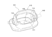
- FIG. 13 is a perspective view showing a schematic configuration of a conventional airflow control device 101.
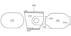
- FIG. 14 is a cross-sectional view of the airflow control device 101 cut along the air flow direction.
- the airflow control device 101 includes a housing 110, a bush (not shown), a shaft body 140, and a valve body 150.
- the housing 110 has a fluid passage 111 therein. A portion of the passage 111 is cut away to form a bush mounting groove 114. A bush is attached to the bush attachment groove 114, and fluid does not flow through the bush attachment groove 114.
- the valve body 150 has a shape that blocks half of the passage 111 in the closed state, and is accommodated in the housing 110.
- the shaft body 140 passes through the bush, the housing 110, and the valve body 150 so that the valve body 150 can rotate. I support it.
- the valve body 150 rotates in synchronization with the shaft body 140 and controls the amount of fluid flowing through the passage 111.
- the cross-sectional shape of the passage 111 is the same oval shape upstream and downstream from the valve body 150, and the cross-sectional area of the passage perpendicular to the flow direction is constant.
- Patent Document 1 discloses an airflow control device including a housing having a flow path for circulating intake air and a valve body that is rotatably accommodated inside the housing to control the amount of intake air. Yes.
- a facing surface portion that faces the peripheral edge portion of the valve body is formed in the middle of the flow path.
- At least a part of the facing surface portion along the inner circumferential direction of the flow path is an inclined surface so as to face only in one direction along the longitudinal direction of the flow path, and the inclined surface is a peripheral portion of the valve body. It is formed in a concave curved surface along the trajectory.
- an object of the present invention is to provide an airflow control device that does not hinder the flow of fluid and does not reduce the intake efficiency even when the flow path area for the valve body is reduced.
- the airflow control device includes a cylindrical housing in which a fluid passage is formed, and two annular bushes attached to the inside of the housing.
- a bush mounting groove is formed by cutting out, and an opening is formed through a portion of the bottom surface of each bush mounting groove, and each bush is connected to the opening.
- the shaft is movably fitted and attached to the housing, and the shaft body is held through the bush while intersecting the dead zone, and has a first cross section perpendicular to the flow direction in the upstream passage.
- the cross-sectional area is larger than the cross-sectional area of the second cross section perpendicular to the flow direction in the downstream passage
- the first cross section has a shape having a first curved portion
- the second cross section has a shape having a second curved portion.
- the curvature of the first bending portion is larger than the curvature of the second bending portion.
- the curvature of the first bending portion is made larger than the curvature of the second bending portion, and the cross-sectional area of the first section is the second. Since it can be made larger than the cross-sectional area of the cross section, it is possible to suppress a reduction in intake efficiency without hindering the flow of fluid in the upstream passage even when the valve body is in an open state.
- the curvature of the second curved portion continuously increases from the second end surface, which is the end surface of the downstream passage, toward the dead zone.
- the bush is attached to the housing so as not to protrude from the bush attachment groove into the passage.
- the passage inside the housing is formed by combining a first mold and a second mold, and the first mold includes the upstream passage, the bush mounting groove, and the dead zone. It is preferable that a part of the downstream side passage and a part of the downstream side passage are formed, and the second mold forms a remaining portion of the downstream side passage and a remaining portion of the dead zone.
- FIG. 3 is a sectional view taken along line III-III in FIG. 2.
- FIG. 3 is a perspective view illustrating a schematic structure of a housing. These are structural drawings when the housing is viewed from the upstream side along the air flow direction.
- FIG. 3 is a cross-sectional view of the housing cut along the air flow direction. These are the VII-VII sectional view taken on the line of FIG. These are the VIII-VIII sectional view taken on the line of FIG. These are the IX-IX sectional view taken on the line of FIG.
- FIG. 12 is a sectional view taken along line XII-XII in FIG. 11. These are perspective views showing the schematic structure of the conventional airflow control apparatus. These are sectional drawings which cut
- FIG. 1 is an explanatory diagram showing an outline of an engine E equipped with an airflow control device 1 according to the present embodiment.
- the airflow control device 1 is provided in the middle of an intake path P1 through which air from an intake manifold (not shown) toward the engine E flows. Air is an example of a fluid. Air is introduced into the combustion chamber C from the intake path P1 by opening the intake valve V1 as the piston Pi of the engine E descends. Exhaust gas after burning in the combustion chamber C passes through the exhaust path P2 via the exhaust valve V2 and is recirculated as necessary, but is finally discharged outside the engine E.
- the airflow control device 1 changes the area of the cross section perpendicular to the air flow direction (hereinafter sometimes simply referred to as “flow direction”) in the intake passage P1 to change the amount of air sucked into the combustion chamber C. Control.
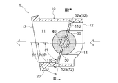
- FIG. 2 shows a cross-sectional view when the airflow control device 1 is cut along the flow direction.
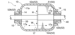
- FIG. 3 is a cross-sectional view taken along line III-III in FIG.
- the airflow control device 1 includes a housing 10 having an air passage 11 therein, two annular bushes 30 attached to the inside of the housing 10, a shaft body 40 held by the bush 30, and the housing 10. And a valve body 50 that is rotatable in synchronization with the shaft body 40, and the shaft body 40 passes through the bush 30, the housing 10, and the valve body 50.
- the white arrow line shown in FIG. 2 represents the flow direction of air.
- the shaft body 40 is a rod-shaped body having a circular cross section, for example, and is inserted through the valve body 50 to support the valve body 50 so as to rotate synchronously.
- the shaft body 40 is configured to pass through the valve bodies 50 of the plurality of airflow control devices 1 arranged in a row with a single shaft body 40.
- the engine E is an in-line four cylinder
- the four valve bodies 50 are penetrated by one shaft body 40.
- One end of the shaft body 40 is connected to an actuator (not shown).
- the rotation of the actuator is controlled by an ECU (not shown) that controls the amount of air flow based on the load of the engine E, the state of the intake valve V1, and the like.
- the valve body 50 is a thin plate member having a uniform thickness disposed inside the housing 10, and is supported by the shaft body 40 so as to be rotatable with respect to the housing 10. As shown in FIG. 2, the valve body 50 rotates to change the cross-sectional area of the passage 11. As shown in FIG. 3, the valve body 50 exists only in half of the passage 11.
- the pressure receiving surface 51 that is a surface when the valve body 50 is viewed along the thickness direction has a rectangular shape in which two corners near the inner peripheral edge of the passage 11 are curved.
- the peripheral surface 52 which is a surface constituting the thickness of the valve body 50, the lateral peripheral surface 52 a parallel to the shaft body 40 is an arcuate curved surface with the shaft body 40 as the center, and is perpendicular to the shaft body 40.
- the vertical peripheral surface 52b is planar.
- a position where the valve body 50 is parallel to the flow direction (a position represented by a two-dot chain line) is set as a reference position.
- the passage 11 is open.
- An angle at which the valve body 50 is rotated around the shaft body 40 from the reference position is defined as ⁇ . That is, the angle ⁇ when the valve body 50 is at the reference position is 0 degree.
- ⁇ c an angle at which the valve body 50 is rotated around the shaft body 40 from the reference position
- a half state of the passage 11 is closed by the valve body 50. In the closed state, the gap between the peripheral surface 52 and the passage 11 is minute, and the amount of air flow is about half that in the open state.
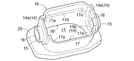
- FIG. 4 is a perspective view showing a schematic structure of the housing 10.
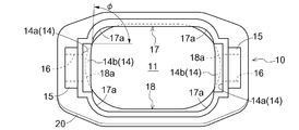
- FIG. 5 shows a structural diagram when the housing 10 is viewed from the upstream side along the flow direction.
- FIG. 6 shows a cross-sectional view of the housing 10 cut along the flow direction.
- the housing 10 has a hollow cylindrical shape inside, and has an octagonal flange 20 with a curved corner at the downstream end.
- the hollow portion constitutes the passage 11.
- the passage 11 is composed of an upstream passage 11a connected to the intake manifold, a dead zone 11b continuously formed from the upstream passage 11a, a dead zone 11b, and a combustion chamber C. And a downstream side passage 11c connected to the intake passage P1.
- FIG. 7 is a sectional view taken along line VII-VII in FIG.
- path 11a has a rectangular shape which has the 1st curved part 17a in which the corner
- the shape of the first cross section 17 is constant with respect to the flow direction.
- the first cross section 17 does not include a bush mounting groove 14 described later.
- the dead zone 11b faces the peripheral surface 52 of the valve body 50 when the valve body 50 closes the passage 11, that is, when the rotation angle of the valve body 50 is ⁇ c.
- Two surfaces in the height direction (H direction in FIG. 3) in the dead zone 11b facing the lateral peripheral surface 52a have inclined surfaces 11d that are inclined in one direction with respect to the flow direction of the upstream passage 11a.
- the inclined surface 11d is formed to be an arcuate curved surface with the attached shaft body 40 as the center. With this, the inclined surface 11d and the lateral peripheral surface 52a are in a state where the valve body 50 is attached. The gap is kept almost constant.
- the length of the inclined surface 11d in the flow direction is larger than the thickness of the valve body 50.
- the angle ⁇ c at which the closed state is established is not a single angle but has a range of “ ⁇ 1 ⁇ ⁇ c ⁇ ⁇ 2” shown in FIG. With such a configuration, it is not necessary to precisely control the rotation angle of the valve body 50 in order to realize the closed state.
- the two opposing surfaces in the width direction (W direction in FIG. 3) of the dead zone 11b are on the same plane as the two opposing surfaces in the W direction of the upstream passage 11a, and there is a minute gap between the vertical peripheral surface 52b.
- the downstream side passage 11c is parallel to the upstream side passage 11a, the length in the H direction is the same as the upstream side passage 11a, and the length in the W direction. Is longer than the upstream passage 11a. That is, as shown in FIGS. 5 and 6, the upstream passage 11a and the downstream passage 11c are shifted in the H direction and not shifted in the W direction.
- FIG. 8 is a cross-sectional view taken along line VIII-VIII in FIG.
- FIG. 9 is a cross-sectional view taken along the line IX-IX in FIG.
- the second cross section 18 perpendicular to the flow direction on the downstream side of the downstream passage 11c (left side in FIG. 6) has a rectangular shape (oval shape) having a second curved portion 18a having a curved corner. Including shape). Then, the curvature of the second bending portion 18a continuously changes so as to go in the direction of the dead zone 11b, and intersects with the alternate long and short dash line indicating the boundary between the dead zone 11b and the downstream passage 11c as shown in FIG.
- a third cross section 19 that is a cross section in the vicinity of the first cross section has substantially the same shape as the first cross section 17.
- the cross sectional area area of the internal space
- the cross-sectional area perpendicular to the flow direction of the passage 11 of the housing 10 becomes smaller in the order of the first cross section 17, the third cross section 19, and the second cross section 18 from upstream to downstream in the flow direction. It is configured.
- FIG. 5 is a cross-sectional area (area of the internal space) between the first cross section 17 (the foremost rectangular space) and the second cross section 18 (the ellipse-shaped space at the back and partially represented by a broken line) shown in FIG. ) Is equal to or larger than the area overlapping the passage 11 when the shaft body 40 and the opened valve body 50 are viewed along the air flow direction.
- This can be realized by making the curvature of the first bending portion 17a larger than the curvature of the second bending portion 18a.
- the cross-sectional area of the portion where the air actually circulates does not become small. It can be smoothly distributed toward the passage 11c.
- the second end face 13 that is the end of the downstream passage 11c is inclined with respect to the flow direction.
- recesses 14 a having a predetermined width are formed on both sides in the W direction on the inner peripheral side of the first end surface 12, which is the end of the upstream passage 11 a, toward the outside.
- the recess 14a extends from the first end surface 12 to the vicinity of the center along the flow direction, and a bush mounting groove 14 is formed.
- the innermost part of the bush mounting groove 14 is a semicircular portion 14 b that matches the outer shape of the bush 30.
- a cylindrical protrusion 15 is formed on both outer sides of the housing 10 coaxially with the center of the semicircular portion 14b, and a circular opening 16 coaxially with the center of the semicircular portion 14b from the bottom surface of the bush mounting groove 14 is formed. Is formed through the housing 10 and the protrusion 15.
- the angle ⁇ formed by the side wall of the bush mounting groove 14 and the first curved portion 17a is about 85 degrees.
- the angle ⁇ is desirably 60 degrees or more.
- the bush 30 has a shape in which two rings of concentric cores having different outer diameters and the same inner diameter are stacked.
- the small outer diameter ring fits into the opening 16, and the large outer diameter ring fits into the semicircular portion 14 b of the bush mounting groove 14.
- the axial thickness of the large outer diameter ring is equal to or less than the depth of the bush mounting groove 14, and the bush 30 does not protrude from the upper surface of the bush mounting groove 14 to the upstream passage 11 a side. Thereby, the bush 30 does not become resistance of air flowing through the passage 11.
- the bush 30 is fitted and fixed to the housing 10 so as to be rotatable.
- the shaft body 40 is inserted into the inner diameter side space of the bush 30 without a gap, and the bush 30 holds the shaft body 40.
- the bush 30 is configured not to protrude from the upper surface of the bush mounting groove 14 toward the upstream passage 11a, but is not limited to this configuration. Although the resistance of air flowing through the passage 11 is somewhat increased, the bush 30 may be configured to protrude from the upper surface of the bush mounting groove 14 toward the upstream passage 11a.
- the valve body 50 has a shape that blocks half of the passage 11 in the closed state, but is not limited to this shape.
- the valve body 50 can take any shape according to the specification of the air flow rate in the closed state, such as a shape that blocks the entire passage 11 in the closed state.
- first cross section 17 and the second cross section 18 have a curved rectangular shape or an oval shape with a constant curvature at the corners, but are not limited thereto.
- the first cross section 17 and / or the second cross section 18 may have an elliptical shape, or may have a shape in which, for example, the long side and the short side are smoothly connected by a curve with a changing curvature.
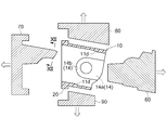
- FIG. 10 is an explanatory view showing a state in which the mold for molding the housing 10 is clamped.
- FIG. 11 is an explanatory view showing a state where a mold for molding the housing 10 is opened.
- FIG. 12 is a cross-sectional view taken along line XII-XII in FIG.
- the housing 10 is formed by injection molding a synthetic resin such as a polyamide resin.
- the first mold 60 and the second mold 70 that form the passage 11 of the housing 10 and the third mold 80 and the fourth mold 90 that form the outer shape of the housing 10 are set in a clamped state. ing.
- a mold that moves in a direction perpendicular to the moving direction of these four types of molds is used. A mold is required, and the protrusion 15 and the opening 16 are formed by this mold.
- the lower half of the upstream passage 11a, the bush attachment groove 14, and the dead zone 11b are formed below the bush attachment groove 14 and the lower half of the downstream passage 11c.
- die 70 the upper half of the downstream channel
- the portion of the second mold 70 where the dead zone 11 b above the bush mounting groove 14 is formed is thinner than the other portions of the second mold 70, and therefore, as shown in FIG. 12. If the molding is repeated with a mold having a small angle ⁇ (less than 60 degrees), the curved corner portion X may be cracked or chipped. However, as shown in FIG. 5, in the housing 10 according to the present embodiment, the curvature of the first curved portion 17a is increased, and the angle ⁇ formed between the side wall of the bush mounting groove 14 and the first curved portion 17a is about 85 degrees. Therefore, as shown in FIG. 12, the angle ⁇ of the curved corner portion X of the second mold 70 for molding the portion of the housing 10 is about 85 degrees. Thereby, sufficient intensity
- the present invention can be used in an airflow control device that is provided in the middle of an intake path to an engine and controls the flow rate of fluid in the intake path.
Landscapes
- Engineering & Computer Science (AREA)
- Chemical & Material Sciences (AREA)
- Combustion & Propulsion (AREA)
- Mechanical Engineering (AREA)
- General Engineering & Computer Science (AREA)
- Control Of Throttle Valves Provided In The Intake System Or In The Exhaust System (AREA)
Description
本発明は、エンジンへの吸気経路途中に設けられ、吸気経路内の流体の流通量を制御する気流制御装置に関する。
エンジンの負荷状態や吸気弁の開閉状態に応じて吸気経路内の流体の流通量を調整する気流制御装置が、インテークマニホールドの下流側かつ吸気弁の上流側に備えられることがある。これにより、体積効率アップによるエンジン出力の向上、流体の速度アップによる燃焼改善、スモークの低減等が実現され、燃費の改善などが見込まれる。気流制御装置は、流体を流通させる通路を備えたハウジングと、ハウジングの内部に回動可能に収容され、流体の吸気量を制御する弁体とを備えている。
図13に、従来の気流制御装置101の概略構成を表す斜視図を示す。図14に、気流制御装置101を空気の流通方向に沿って切断した断面図を示す。気流制御装置101は、ハウジング110とブッシュ(不図示)と軸体140と弁体150を備える。ハウジング110は、内部に流体の通路111を有する。通路111の一部は切り欠かれてブッシュ取付溝114が形成されている。ブッシュ取付溝114にはブッシュが取り付けられており、流体はブッシュ取付溝114を流通しない。弁体150は閉じ状態で通路111の半分を遮断する形状を備えてハウジング110の内部に収容され、軸体140はブッシュとハウジング110と弁体150を貫通し、弁体150を回動可能に支持している。弁体150は軸体140と同期して回転し、通路111を流通する流体の流通量を制御する。図14に示すように、通路111の断面の形状は弁体150より上流側も下流側も同じ長円形状で流通方向に垂直な通路の断面積も一定である。
また、特許文献1には、吸気を流通させる流路を備えたハウジングと、吸気の量を制御すべくハウジングの内部に回転可能に収容される弁体とを備えた気流制御装置が開示されている。この気流制御装置においては、弁体が閉じ状態にあるとき弁体の周縁部に対向する対向面部が流路の途中に形成されている。対向面部のうち流路の内周方向に沿った少なくとも一部は、流路の長手方向に沿った一方向側にのみ面するよう傾斜面となっており、傾斜面は弁体の周縁部の軌跡に沿った凹曲面状に形成されている。
図13、図14に示すように、従来の気流制御装置101においては、軸体140および弁体150が存在することにより、弁体150が開き状態であっても弁体150より上流側の流路面積が低下していた。そのため、流体の流通が妨げられ、吸気効率が低下するという問題があった。
上記問題に鑑み、本発明は、弁体分の流路面積が低下した場合でも、流体の流通を妨げず、吸気効率を低下させない気流制御装置を提供することを課題とする。
上記課題を解決するために、本発明に係る気流制御装置の特徴構成は、内部が流体の通路になっている筒状のハウジングと、前記ハウジングの内部に取り付けられた2個の環状のブッシュと、前記ブッシュに保持される軸体と、前記ハウジングの内部に取り付けられ、前記軸体と同期して回動可能な弁体と、を備え、前記通路には、上流側通路と、前記上流側通路に連続的に接続され且つ前記弁体が所定の姿勢にあるときに前記上流側通路との流通が遮断される不感帯と、前記不感帯に対して前記上流側通路と反対側に配置された下流側通路とが含まれており、前記通路の一部には、前記上流側通路の端面である第1端面の内周側の対向する2辺からそれぞれ外側に向けて形成した窪みを流通方向に沿って前記通路の中央付近まで延伸されたブッシュ取付溝が切り欠かれて形成されており、それぞれの前記ブッシュ取付溝の底面の一部には前記ハウジングを貫通する開孔が形成されており、それぞれの前記ブッシュは、前記開孔と回動可能に嵌合し前記ハウジングに取り付けられており、前記軸体は、前記不感帯と交差しつつ前記ブッシュを貫通して保持されており、前記上流側通路において流通方向に垂直な第1断面の断面積は、前記下流側通路において流通方向に垂直な第2断面の断面積より大きく、前記第1断面は第1湾曲部を有する形状であり、前記第2断面は第2湾曲部を有する形状であり、前記第1湾曲部の曲率が前記第2湾曲部の曲率よりも大きい点にある。
このような特徴構成であれば、通路の途中に軸体と弁体があっても、第1湾曲部の曲率を第2湾曲部の曲率よりも大きくして第1断面の断面積が第2断面の断面積より大きくすることができるので、弁体が開き状態であっても上流側通路の流体の流通を妨げることなく、吸気効率の低下を抑制することができる。
本発明の気流制御装置において、前記第2湾曲部の曲率は、前記下流側通路の端面である第2端面から前記不感帯に向かうにつれて連続的に大きくなると好適である。
このような構成であれば、曲率の変化があっても流体の流通を妨げる抵抗にならないので、吸気効率の低下を抑制することができる。
本発明の気流制御装置において、前記ブッシュは、前記ブッシュ取付溝から前記通路に突出しないよう前記ハウジングに取り付けられると好適である。
このような構成であれば、ブッシュが流体の流通を妨げる抵抗にならないので、吸気効率の低下を抑制することができる。
本発明の気流制御装置において、前記ハウジングの内部の通路は第1金型と第2金型とを組み合わせて形成され、前記第1金型は前記上流側通路、前記ブッシュ取付溝、前記不感帯の一部および前記下流側通路の一部を形成し、前記第2金型は前記下流側通路の残部と前記不感帯の残部を形成すると好適である。
このような構成であれば、ハウジング全体の成形にはスライドコアを必要とするものの、ハウジング内部の通路の成形には、複雑な金型構造にせずに成形することができる。
1.気流制御装置の構成
以下、本発明の実施の形態について、詳細に説明する。図1に、本実施形態に係る気流制御装置1を搭載したエンジンEの概要を表す説明図である。気流制御装置1は、不図示のインテークマニホールドからエンジンEへ向かう空気が流通する吸気経路P1の途中に設けられている。空気は流体の一例である。空気は、エンジンEのピストンPiの下降に伴って吸気弁V1が開くことにより、吸気経路P1から燃焼室Cに導入される。燃焼室Cで燃焼した後の排気ガスは、排気弁V2を介して排気経路P2を通り、必要に応じて再循環されるものの、最終的にはエンジンEの外部に排出される。気流制御装置1は、吸気経路P1における空気の流通方向(以下、単に「流通方向」と称する場合もある)に垂直な断面の面積を変化させて、燃焼室Cに吸入される空気の量を制御する。
以下、本発明の実施の形態について、詳細に説明する。図1に、本実施形態に係る気流制御装置1を搭載したエンジンEの概要を表す説明図である。気流制御装置1は、不図示のインテークマニホールドからエンジンEへ向かう空気が流通する吸気経路P1の途中に設けられている。空気は流体の一例である。空気は、エンジンEのピストンPiの下降に伴って吸気弁V1が開くことにより、吸気経路P1から燃焼室Cに導入される。燃焼室Cで燃焼した後の排気ガスは、排気弁V2を介して排気経路P2を通り、必要に応じて再循環されるものの、最終的にはエンジンEの外部に排出される。気流制御装置1は、吸気経路P1における空気の流通方向(以下、単に「流通方向」と称する場合もある)に垂直な断面の面積を変化させて、燃焼室Cに吸入される空気の量を制御する。
図2に、気流制御装置1を流通方向に沿って切断したときの断面図を示す。図3に、図2のIII-III線断面図を示す。気流制御装置1は、内部が空気の通路11になっているハウジング10と、ハウジング10の内部に取り付けられる2個の円環状のブッシュ30と、ブッシュ30に保持される軸体40と、ハウジング10の内部に取り付けられ且つ軸体40と同期して回動可能な弁体50とを備えており、軸体40はブッシュ30とハウジング10と弁体50とを貫通している。図2に示す白抜き矢線は空気の流通方向を表す。
図2、図3に示すように、軸体40は例えば断面が円形の棒状体であり、弁体50に挿通され、弁体50を同期回転させるように支持している。軸体40は、一列に配置された複数の気流制御装置1の弁体50を一本の軸体40で貫通するように構成されている。例えばエンジンEが直列4気筒であれば4つの弁体50を1本の軸体40で貫く。軸体40の一方の端部は不図示のアクチュエータに接続されている。アクチュエータは、エンジンEの負荷、吸気弁V1の状態等に基づく空気の流通量を制御する不図示のECUにより回転が制御される。アクチュエータが駆動すると軸体40が回動し、それに同期して弁体50が回動する。
弁体50は、ハウジング10の内部に配置された均一な厚みの薄板状部材で、軸体40によってハウジング10に対して回動可能に支持されている。図2に示すように、弁体50が回動することにより通路11の断面積を変化させる。図3に示すように、弁体50は通路11の半分だけに存在している。弁体50を厚み方向に沿って見たときの面である受圧面51は、通路11の内周縁に近い2つの角部が湾曲している矩形状を有している。弁体50の厚みを構成する面である周縁面52のうち、軸体40と平行な横周縁面52aは軸体40を中心とした円弧状の曲面となっており、軸体40に垂直な縦周縁面52bは平面状となっている。
図2に示すように、弁体50が流通方向と平行になる位置(二点鎖線で表された位置)を基準位置とする。弁体50が基準位置にあるときには、通路11は開き状態である。基準位置から軸体40を中心に弁体50が回動した角度をθとする。すなわち、弁体50が基準位置にあるときの角度θは0度である。また、弁体50が基準位置から所定角度θcだけ回動すると、通路11の半分が弁体50によって遮断される閉じ状態となる。閉じ状態では、周縁面52と通路11の間隙が微小となり、空気の流通量は開き状態と比較して約半分になる。
図4に、ハウジング10の概略構造を表す斜視図を示す。図5に、ハウジング10を流通方向に沿って上流側から見たときの構造図を示す。図6に、ハウジング10を流通方向に沿って切断した断面図を示す。図4、図6に示すように、ハウジング10は、内部が中空の筒状を有しており、下流側の端部には角部が湾曲した八角形状のフランジ20を有している。中空の箇所は通路11を構成する。
図6に示すように、通路11は、インテークマニホールドに接続される上流側通路11aと、上流側通路11aから連続的に構成された不感帯11bと、不感帯11bから連続的に構成され且つ燃焼室Cにつながる吸気経路P1に接続される下流側通路11cとを備えている。図7に図6のVII-VII線断面図を示す。図7に示すように、上流側通路11aにおける流通方向に垂直な第1断面17は、角部が湾曲した第1湾曲部17aを有する矩形状を有している。第1断面17の形状は流通方向に対して一定である。なお、第1断面17には、後述するブッシュ取付溝14は含まれない。
不感帯11bは、図2、図6で示すように、弁体50が通路11を閉じ状態とする位置、すなわち弁体50の回転角度がθcであるときの弁体50の周縁面52と対向する位置に設けられている。横周縁面52aと対向する不感帯11bにおける高さ方向(図3のH方向)の2面は上流側通路11aの流通方向に対して一方向に傾斜する傾斜面11dを有している。傾斜面11dは、取り付けられた軸体40を中心とする円弧状の曲面になるように形成されており、これにより、弁体50が取り付けられた状態で、傾斜面11dと横周縁面52aの間隙はほぼ一定に維持される。
また、傾斜面11dの流通方向への長さは弁体50の厚みよりも大きいものとなっている。これにより、閉じ状態となる角度θcは単一角度ではなく、図2に示す「θ1≦θc≦θ2」の範囲を有する。このような構成により、閉じ状態を実現するために弁体50の回動角度を精緻に制御する必要はない。なお、不感帯11bの幅方向(図3のW方向)の対向する2面は上流側通路11aのW方向の対向する2面と同一平面上にあり、縦周縁面52bとの間に微小な間隙を有する。
下流側通路11cは、不感帯11bの上流側通路11aと反対側の端部から、流通方向が上流側通路11aと平行に、H方向の長さが上流側通路11aと同じ且つW方向の長さが上流側通路11aより長くなるように延在している。すなわち、図5、図6に示すように、上流側通路11aと下流側通路11cとはH方向にずれており、W方向にはずれていない。
図8に、図6のVIII-VIII線断面図を示す。図9に、図6のIX-IX線断面図を示す。図8に示すように、下流側通路11cの下流側(図6の左側)における、流通方向に垂直な第2断面18は、角部が湾曲した第2湾曲部18aを有する矩形状(長円形状を含む)を有している。そして、不感帯11bの方向に向かうにつれて第2湾曲部18aの曲率が大きくなるように連続的に変化し、図9に示すように、不感帯11bと下流側通路11cとの境界を示す一点鎖線と交差する近傍での断面である第3断面19は、第1断面17とほぼ同じ形状になる。第2湾曲部18aの曲率が変化し第2断面18から第3断面19へ形状が変化するにつれ断面積(内部の空間の面積)は徐々に大きくなる。以上をまとめると、ハウジング10の通路11の流通方向に垂直な断面積は、流通方向上流から下流に向かうにつれ、すなわち第1断面17、第3断面19、第2断面18の順に小さくなるように構成されている。
また、図5に示す第1断面17(最前面の矩形状空間)と第2断面18(奥にあり一部破線で表されている長円形状空間)との断面積(内部の空間の面積)の差は、軸体40および開き状態の弁体50を空気の流通方向に沿って見たときに通路11と重なる面積以上である。これは、第1湾曲部17aの曲率を第2湾曲部18aの曲率より大きくすることにより実現することができる。これにより、弁体50の開き状態で通路11の途中に軸体40や弁体50があっても実際に空気が流通する部分の断面積が小さくならないので、空気を上流側通路11aから下流側通路11cに向けてスムーズに流通させることができる。なお、図2、図6に示すように、下流側通路11cの端部である第2端面13は流通方向に対して傾斜している。
図4、図5に示すように、上流側通路11aの端部である第1端面12の内周側のW方向の両辺には外側に向けて所定の幅を有する窪み14aが形成されており、その窪み14aは第1端面12から流通方向に沿って中央付近まで延伸され、ブッシュ取付溝14が形成されている。ブッシュ取付溝14の最奥はブッシュ30の外形状に合わせた半円部14bになっている。そして、半円部14bの中心と同軸芯でハウジング10の両外側に円柱状の突出部15が形成され、ブッシュ取付溝14の底面から半円部14bの中心と同軸芯の円形の開孔16がハウジング10と突出部15を貫通して形成されている。
図5に示すように、ブッシュ取付溝14の側壁と第1湾曲部17aのなす角度φは約85度となる。角度φは60度以上であることが望ましい。このように第1湾曲部17aの曲率を大きくして角度φを大きくすることにより、ブッシュ取付溝14を設けても、ハウジング10を射出成形で形成するときの金型の強度を十分に確保することができる。ハウジング10の成形方法の詳細については後述する。
本実施形態において、ブッシュ30は図3に示すように、同芯で外径が異なり内径が同径の円環を2段重ねた形状を有している。小外径の円環は開孔16と嵌合し、大外径の円環はブッシュ取付溝14の半円部14bと嵌合する。大外径の円環の軸方向の厚みはブッシュ取付溝14の深さ以下であり、ブッシュ30はブッシュ取付溝14の上面から上流側通路11a側に突出していない。これにより、ブッシュ30は、通路11を流通する空気の抵抗にならない。ブッシュ30は、ハウジング10に回動可能に嵌合して固定されている。ブッシュ30の内径側空間には軸体40が隙間なく挿通され、ブッシュ30は軸体40を保持する。
本実施形態においては、ブッシュ30はブッシュ取付溝14の上面から上流側通路11a側に突出していない構成となっているが、この構成に限られるものではない。通路11を流通する空気の抵抗が多少増大するが、ブッシュ30がブッシュ取付溝14の上面から上流側通路11a側に突出した構成であってもよい。また、本実施形態においては、弁体50は閉じ状態で通路11の半分を遮断する形状であったが、この形状に限られるものではない。例えば閉じ状態で通路11の全部を遮断する形状など、弁体50は閉じ状態での空気の流通量の仕様に応じて任意の形状を採ることができる。
本実施形態においては、第1断面17および第2断面18は角部が一定な曲率を有する湾曲した矩形状、長円形状としたが、これだけに限られるものではない。第1断面17および/または第2断面18が楕円形状であってもよいし、その他、例えば長辺と短辺とが曲率の変化する曲線で滑らかにつながれた形状であってもよい。
2.ハウジングの製造方法
次に、本実施形態に係る気流制御装置1のハウジング10の製造方法について、図面を用いて説明する。図10に、ハウジング10を成形する金型が型締された状態を表す説明図を示す。また、図11に、ハウジング10を成形する金型が型開された状態を表す説明図を示す。図12に、図11のXII-XII線断面図を示す。
次に、本実施形態に係る気流制御装置1のハウジング10の製造方法について、図面を用いて説明する。図10に、ハウジング10を成形する金型が型締された状態を表す説明図を示す。また、図11に、ハウジング10を成形する金型が型開された状態を表す説明図を示す。図12に、図11のXII-XII線断面図を示す。
ハウジング10は、ポリアミド樹脂などの合成樹脂を射出成形して形成される。図10には、ハウジング10の通路11を形成する第1金型60と第2金型70、ハウジング10の外形を形成する第3金型80、第4金型90が型締状態にセットされている。図10、図11では不図示であるが、実際にハウジング10を成形するためには、これらの4種類の金型以外に、これら4種類の金型の移動方向に垂直な方向に移動する金型が必要であり、この金型により突出部15や開孔16が形成される。
第1金型60では、上流側通路11a、ブッシュ取付溝14、不感帯11bのうちブッシュ取付溝14よりも下側および下流側通路11cの下半分を形成する。第2金型70では、下流側通路11cの上半分と不感帯11bのブッシュ取付溝14よりも上側を形成する。
図11に示すように、第2金型70のうちブッシュ取付溝14よりも上側の不感帯11bを形成する箇所は第2金型70の他の箇所と比べて厚みが薄いため、図12に示す角度φが小さい(60度未満)金型で成形を繰り返し行うと、湾曲角部Xが割れたり欠けたりするおそれがある。しかし、図5に示すように、本実施形態に係るハウジング10は、第1湾曲部17aの曲率を大きくして、ブッシュ取付溝14の側壁と第1湾曲部17aのなす角度φを約85度になるようにしたので、図12に示すように、ハウジング10の当該箇所を成形する第2金型70の湾曲角部Xの角度φも約85度である。これにより、湾曲角部Xにおいて十分な強度を確保することができ、第2金型70の割れや欠けを防止できる。
本発明は、エンジンへの吸気経路途中に設けられ、吸気経路内の流体の流通量を制御する気流制御装置に用いることが可能である。
1 気流制御装置
10 ハウジング
11 通路
11a 上流側通路
11b 不感帯
11c 下流側通路
12 第1端面
13 第2端面
14 ブッシュ取付溝
14a 窪み
16 開孔
17 第1断面
17a 第1湾曲部
18 第2断面
18a 第2湾曲部
30 ブッシュ
40 軸体
50 弁体
60 第1金型
70 第2金型
10 ハウジング
11 通路
11a 上流側通路
11b 不感帯
11c 下流側通路
12 第1端面
13 第2端面
14 ブッシュ取付溝
14a 窪み
16 開孔
17 第1断面
17a 第1湾曲部
18 第2断面
18a 第2湾曲部
30 ブッシュ
40 軸体
50 弁体
60 第1金型
70 第2金型
Claims (4)
- 内部が流体の通路になっている筒状のハウジングと、
前記ハウジングの内部に取り付けられた2個の環状のブッシュと、
前記ブッシュに保持される軸体と、
前記ハウジングの内部に取り付けられ、前記軸体と同期して回動可能な弁体と、を備え、
前記通路には、上流側通路と、前記上流側通路に連続的に接続され且つ前記弁体が所定の姿勢にあるときに前記上流側通路との流通が遮断される不感帯と、前記不感帯に対して前記上流側通路と反対側に配置された下流側通路とが含まれており、
前記通路の一部には、前記上流側通路の端面である第1端面の内周側の対向する2辺からそれぞれ外側に向けて形成した窪みを流通方向に沿って前記通路の中央付近まで延伸されたブッシュ取付溝が切り欠かれて形成されており、
それぞれの前記ブッシュ取付溝の底面の一部には前記ハウジングを貫通する開孔が形成されており、
それぞれの前記ブッシュは、前記開孔と回動可能に嵌合し前記ハウジングに取り付けられており、
前記軸体は、前記不感帯と交差しつつ前記ブッシュを貫通して保持されており、
前記上流側通路において流通方向に垂直な第1断面の断面積は、前記下流側通路において流通方向に垂直な第2断面の断面積より大きく、
前記第1断面は第1湾曲部を有する形状であり、
前記第2断面は第2湾曲部を有する形状であり、
前記第1湾曲部の曲率が前記第2湾曲部の曲率より大きい気流制御装置。 - 前記第2湾曲部の曲率は、前記下流側通路の端面である第2端面から前記不感帯に向かうにつれて連続的に大きくなる請求項1に記載の気流制御装置。
- 前記ブッシュは、前記ブッシュ取付溝から前記通路に突出しないよう前記ハウジングに取り付けられる請求項1または2に記載の気流制御装置。
- 前記ハウジングの内部の通路は第1金型と第2金型とを組み合わせて形成され、前記第1金型は前記上流側通路、前記ブッシュ取付溝、前記不感帯の一部および前記下流側通路の一部を形成し、前記第2金型は前記下流側通路の残部と前記不感帯の残部を形成する請求項1乃至3のいずれか1項に記載の気流制御装置。
Priority Applications (1)
| Application Number | Priority Date | Filing Date | Title |
|---|---|---|---|
| US14/412,091 US20150136078A1 (en) | 2012-07-04 | 2013-06-28 | Airflow control apparatus |
Applications Claiming Priority (2)
| Application Number | Priority Date | Filing Date | Title |
|---|---|---|---|
| JP2012-150724 | 2012-07-04 | ||
| JP2012150724A JP5867322B2 (ja) | 2012-07-04 | 2012-07-04 | 気流制御装置 |
Publications (1)
| Publication Number | Publication Date |
|---|---|
| WO2014007178A1 true WO2014007178A1 (ja) | 2014-01-09 |
Family
ID=49881934
Family Applications (1)
| Application Number | Title | Priority Date | Filing Date |
|---|---|---|---|
| PCT/JP2013/067904 Ceased WO2014007178A1 (ja) | 2012-07-04 | 2013-06-28 | 気流制御装置 |
Country Status (3)
| Country | Link |
|---|---|
| US (1) | US20150136078A1 (ja) |
| JP (1) | JP5867322B2 (ja) |
| WO (1) | WO2014007178A1 (ja) |
Families Citing this family (1)
| Publication number | Priority date | Publication date | Assignee | Title |
|---|---|---|---|---|
| US11536230B1 (en) | 2021-10-26 | 2022-12-27 | Ford Global Technologies, Llc | Charge-air cooler and water distribution device to evenly proved water to engine cylinders |
Citations (6)
| Publication number | Priority date | Publication date | Assignee | Title |
|---|---|---|---|---|
| JP2002021587A (ja) * | 2000-07-05 | 2002-01-23 | Aisan Ind Co Ltd | 内燃機関の吸気装置 |
| JP2004285893A (ja) * | 2003-03-20 | 2004-10-14 | Aisin Seiki Co Ltd | 吸気装置 |
| JP2005113912A (ja) * | 2003-10-06 | 2005-04-28 | Filterwerk Mann & Hummel Gmbh | 特に内燃機関用の吸気モジュール |
| JP2005315258A (ja) * | 2004-04-29 | 2005-11-10 | Filterwerk Mann & Hummel Gmbh | 内燃機関吸気装置のフランジ部におけるフラップ弁装置 |
| JP2010024979A (ja) * | 2008-07-18 | 2010-02-04 | Toyota Boshoku Corp | 吸気マニホールド |
| WO2012099191A1 (ja) * | 2011-01-21 | 2012-07-26 | 株式会社小松製作所 | 送気管及び過給器 |
Family Cites Families (39)
| Publication number | Priority date | Publication date | Assignee | Title |
|---|---|---|---|---|
| DE2829398C2 (de) * | 1978-06-30 | 1982-09-23 | Deutsche Vergaser Gesellschaft, 1000 Berlin | Wellenlagerung für die Drosselklappe von Luftregel- und Gemischaufbereitungseinrichtungen, insbesondere Vergaser |
| DE3244103A1 (de) * | 1982-11-29 | 1984-05-30 | Vdo Adolf Schindling Ag, 6000 Frankfurt | Drosselklappenstutzen |
| US4491106A (en) * | 1982-11-29 | 1985-01-01 | Morris George Q | Throttle configuration achieving high velocity channel at partial opening |
| JPH05296067A (ja) * | 1992-04-20 | 1993-11-09 | Aisan Ind Co Ltd | 内燃機関用吸気制御装置 |
| FR2692622B1 (fr) * | 1992-06-17 | 1994-09-16 | Solex | Organe d'étranglement rotatif pour installation d'alimentation de moteur à combustion interne et corps de papillon en comportant application. |
| FR2694963B1 (fr) * | 1992-08-21 | 1994-10-21 | Solex | Corps de papillon à conduit d'admission de forme évolutive et procédé de fabrication d'un tel corps. |
| DE4240127C2 (de) * | 1992-11-28 | 1997-04-24 | Bosch Gmbh Robert | Drosselvorrichtung für eine Brennkraftmaschine und Verfahren zur Herstellung von Dosierwandungen in der Drosselvorrichtung |
| EP0869266A4 (en) * | 1995-12-19 | 2000-06-21 | Hitachi Ltd | THROTTLE VALVE ACTUATING DEVICE FOR COMBUSTION ENGINES |
| FR2762374B1 (fr) * | 1997-04-18 | 1999-06-04 | Coutier Moulage Gen Ind | Vanne papillon pour la regulation du debit d'un fluide et ses procedes de fabrication |
| DE19918777A1 (de) * | 1999-04-24 | 2000-10-26 | Mann & Hummel Filter | Schaltklappenverband aus montagegespritzten Schaltklappen oder Klappenmodulen |
| US6764062B1 (en) * | 1999-06-29 | 2004-07-20 | Siemens Vdo Automotive, Inc. | Plastic throttle body |
| US6454242B1 (en) * | 2001-02-15 | 2002-09-24 | Delphi Technologies, Inc. | Modified flow throttle bore |
| DE10140394A1 (de) * | 2001-08-23 | 2003-03-06 | Siemens Ag | Drosselklappenstutzen für einen Verbrennungsmotor |
| DE10140409A1 (de) * | 2001-08-23 | 2003-03-13 | Siemens Ag | Verfahren zur Herstellung eines Gehäuses oder eines Einsatzteils für ein Gehäuse eines Drosselklappenstutzens sowie Drosselklappenstutzen |
| DE10142452A1 (de) * | 2001-08-31 | 2003-03-20 | Siemens Ag | Verfahren zur Herstellung eines Drosselklappenstutzengehäuses und einer Drosselklappe |
| JP3872743B2 (ja) * | 2002-03-28 | 2007-01-24 | 株式会社日立製作所 | スロットルバルブ開閉装置 |
| JP2004068794A (ja) * | 2002-08-02 | 2004-03-04 | Aisan Ind Co Ltd | 可変吸気バルブ |
| DE10240624A1 (de) * | 2002-09-03 | 2004-03-11 | Siemens Ag | Verfahren zum Abschließen eines Drosselklappenstutzens |
| DE10246726A1 (de) * | 2002-10-07 | 2004-04-15 | Siemens Ag | Verfahren zur Herstellung einer Drosselklappe in einem durchgehenden Drosselklappenstutzen |
| JP2004132235A (ja) * | 2002-10-09 | 2004-04-30 | Aisan Ind Co Ltd | スロットル制御装置 |
| JP2004132237A (ja) * | 2002-10-09 | 2004-04-30 | Aisan Ind Co Ltd | スロットル制御装置 |
| JP2004132232A (ja) * | 2002-10-09 | 2004-04-30 | Aisan Ind Co Ltd | スロットル制御装置 |
| DE10327045A1 (de) * | 2003-06-16 | 2005-04-07 | Siemens Ag | Drosselklappen-Verstellvorrichtung |
| DE10329484A1 (de) * | 2003-07-01 | 2005-01-27 | Robert Bosch Gmbh | Verfahren zur Herstellung einer Drosselklappeneinheit im Zweikomponentenspritz-Giessverfahren |
| JP4103721B2 (ja) * | 2003-08-01 | 2008-06-18 | 株式会社デンソー | 内燃機関用スロットル装置の成形方法 |
| JP4207825B2 (ja) * | 2003-11-07 | 2009-01-14 | 株式会社デンソー | 内燃機関用スロットル装置の成形方法 |
| JP4269899B2 (ja) * | 2003-11-07 | 2009-05-27 | 株式会社デンソー | 内燃機関用スロットル装置の射出成形方法 |
| US7716828B2 (en) * | 2004-05-31 | 2010-05-18 | Aisan Kogyo Kabushiki Kaisha | Method of manufacturing throttle body, and throttle body |
| US7574797B2 (en) * | 2004-07-22 | 2009-08-18 | Ford Global Technologies, Llc | Throttle body and method of assembly |
| US7032885B2 (en) * | 2004-07-22 | 2006-04-25 | Automotive Components Holdings, Llc | Throttle body and method of assembly |
| US8342148B2 (en) * | 2006-01-20 | 2013-01-01 | Ford Global Technologies | Throttle valve for internal combustion engine |
| US7958863B2 (en) * | 2006-05-24 | 2011-06-14 | Toyota Jidosha Kabushiki Kaisha | Intake device for internal combustion engine |
| JP4142696B2 (ja) * | 2006-06-14 | 2008-09-03 | トヨタ自動車株式会社 | 内燃機関のスロットルバルブ加熱制御装置 |
| JP4605476B2 (ja) * | 2006-09-21 | 2011-01-05 | アイシン精機株式会社 | 吸気制御装置 |
| JP4457115B2 (ja) * | 2007-01-16 | 2010-04-28 | 日立オートモティブシステムズ株式会社 | バタフライ式弁装置 |
| US20080223450A1 (en) * | 2007-03-15 | 2008-09-18 | Aisan Kogyo Kabushiki Kaisha | Flow control valves |
| JP4630318B2 (ja) * | 2007-08-29 | 2011-02-09 | 本田技研工業株式会社 | 内燃機関のスロットル装置 |
| US8056534B2 (en) * | 2009-05-22 | 2011-11-15 | Ford Global Technologies | Intake manifold system for internal combustion engine |
| DE102010054838A1 (de) * | 2010-12-16 | 2012-06-21 | Andreas Stihl Ag & Co. Kg | Zweitaktmotor |
-
2012
- 2012-07-04 JP JP2012150724A patent/JP5867322B2/ja not_active Expired - Fee Related
-
2013
- 2013-06-28 US US14/412,091 patent/US20150136078A1/en not_active Abandoned
- 2013-06-28 WO PCT/JP2013/067904 patent/WO2014007178A1/ja not_active Ceased
Patent Citations (6)
| Publication number | Priority date | Publication date | Assignee | Title |
|---|---|---|---|---|
| JP2002021587A (ja) * | 2000-07-05 | 2002-01-23 | Aisan Ind Co Ltd | 内燃機関の吸気装置 |
| JP2004285893A (ja) * | 2003-03-20 | 2004-10-14 | Aisin Seiki Co Ltd | 吸気装置 |
| JP2005113912A (ja) * | 2003-10-06 | 2005-04-28 | Filterwerk Mann & Hummel Gmbh | 特に内燃機関用の吸気モジュール |
| JP2005315258A (ja) * | 2004-04-29 | 2005-11-10 | Filterwerk Mann & Hummel Gmbh | 内燃機関吸気装置のフランジ部におけるフラップ弁装置 |
| JP2010024979A (ja) * | 2008-07-18 | 2010-02-04 | Toyota Boshoku Corp | 吸気マニホールド |
| WO2012099191A1 (ja) * | 2011-01-21 | 2012-07-26 | 株式会社小松製作所 | 送気管及び過給器 |
Also Published As
| Publication number | Publication date |
|---|---|
| JP5867322B2 (ja) | 2016-02-24 |
| JP2014013014A (ja) | 2014-01-23 |
| US20150136078A1 (en) | 2015-05-21 |
Similar Documents
| Publication | Publication Date | Title |
|---|---|---|
| CN103982346A (zh) | 进气歧管 | |
| CN105683550A (zh) | 内燃机的气缸体 | |
| JP5867322B2 (ja) | 気流制御装置 | |
| JP5054502B2 (ja) | 掃気カバーおよび2サイクルエンジン | |
| US10196969B2 (en) | Exhaust device for engine | |
| JP6589580B2 (ja) | 内燃機関の吸気装置および吸気流制御弁 | |
| US8714136B2 (en) | Direct fuel-injection engine | |
| JP6303541B2 (ja) | 内燃機関の吸気構造および吸気装置 | |
| CN103061896B (zh) | 具有至少两个分开制造的和为了共同运动而相互装配在一起的节气门的节气门装置 | |
| CN104838123B (zh) | 缸盖的预成形品、缸盖及缸盖的制造方法 | |
| JP2009127522A (ja) | 気流制御装置及びその製造方法 | |
| US8015959B2 (en) | Valve shaft support structure for variable intake manifold | |
| JP6172191B2 (ja) | エンジンの吸気構造 | |
| US11255275B2 (en) | Intake device | |
| JP2006207469A (ja) | 内燃機関の吸気マニホールド | |
| CN2861507Y (zh) | 内燃机进气结构 | |
| JP2023104199A (ja) | 内燃機関のシリンダヘッド | |
| JP4922213B2 (ja) | 燃料直噴エンジン | |
| JP6213510B2 (ja) | エンジンのシリンダヘッドの製造方法 | |
| EP1279812A2 (en) | Intake air control devices for internal combustion engines | |
| JP6172192B2 (ja) | エンジンのシリンダヘッドの製造方法 | |
| US10036354B2 (en) | Intake apparatus of internal combustion engine | |
| JP5633488B2 (ja) | 流体制御弁 | |
| CN205243692U (zh) | V型发动机的进气结构 | |
| CN106687724A (zh) | 开闭阀结构 |
Legal Events
| Date | Code | Title | Description |
|---|---|---|---|
| 121 | Ep: the epo has been informed by wipo that ep was designated in this application |
Ref document number: 13813034 Country of ref document: EP Kind code of ref document: A1 |
|
| WWE | Wipo information: entry into national phase |
Ref document number: 14412091 Country of ref document: US |
|
| NENP | Non-entry into the national phase |
Ref country code: DE |
|
| 122 | Ep: pct application non-entry in european phase |
Ref document number: 13813034 Country of ref document: EP Kind code of ref document: A1 |