WO2014007126A1 - ジョイント端子 - Google Patents
ジョイント端子 Download PDFInfo
- Publication number
- WO2014007126A1 WO2014007126A1 PCT/JP2013/067539 JP2013067539W WO2014007126A1 WO 2014007126 A1 WO2014007126 A1 WO 2014007126A1 JP 2013067539 W JP2013067539 W JP 2013067539W WO 2014007126 A1 WO2014007126 A1 WO 2014007126A1
- Authority
- WO
- WIPO (PCT)
- Prior art keywords
- terminal
- joint
- joint terminal
- side wall
- adjacent
- Prior art date
- Legal status (The legal status is an assumption and is not a legal conclusion. Google has not performed a legal analysis and makes no representation as to the accuracy of the status listed.)
- Ceased
Links
Images






Classifications
-
- H—ELECTRICITY
- H01—ELECTRIC ELEMENTS
- H01R—ELECTRICALLY-CONDUCTIVE CONNECTIONS; STRUCTURAL ASSOCIATIONS OF A PLURALITY OF MUTUALLY-INSULATED ELECTRICAL CONNECTING ELEMENTS; COUPLING DEVICES; CURRENT COLLECTORS
- H01R13/00—Details of coupling devices of the kinds covered by groups H01R12/70 or H01R24/00 - H01R33/00
- H01R13/02—Contact members
- H01R13/22—Contacts for co-operating by abutting
- H01R13/24—Contacts for co-operating by abutting resilient; resiliently-mounted
- H01R13/2407—Contacts for co-operating by abutting resilient; resiliently-mounted characterized by the resilient means
- H01R13/2414—Contacts for co-operating by abutting resilient; resiliently-mounted characterized by the resilient means conductive elastomers
-
- H—ELECTRICITY
- H01—ELECTRIC ELEMENTS
- H01R—ELECTRICALLY-CONDUCTIVE CONNECTIONS; STRUCTURAL ASSOCIATIONS OF A PLURALITY OF MUTUALLY-INSULATED ELECTRICAL CONNECTING ELEMENTS; COUPLING DEVICES; CURRENT COLLECTORS
- H01R13/00—Details of coupling devices of the kinds covered by groups H01R12/70 or H01R24/00 - H01R33/00
- H01R13/02—Contact members
- H01R13/04—Pins or blades for co-operation with sockets
- H01R13/05—Resilient pins or blades
-
- H—ELECTRICITY
- H01—ELECTRIC ELEMENTS
- H01R—ELECTRICALLY-CONDUCTIVE CONNECTIONS; STRUCTURAL ASSOCIATIONS OF A PLURALITY OF MUTUALLY-INSULATED ELECTRICAL CONNECTING ELEMENTS; COUPLING DEVICES; CURRENT COLLECTORS
- H01R13/00—Details of coupling devices of the kinds covered by groups H01R12/70 or H01R24/00 - H01R33/00
- H01R13/02—Contact members
- H01R13/10—Sockets for co-operation with pins or blades
- H01R13/11—Resilient sockets
- H01R13/113—Resilient sockets co-operating with pins or blades having a rectangular transverse section
-
- H—ELECTRICITY
- H01—ELECTRIC ELEMENTS
- H01R—ELECTRICALLY-CONDUCTIVE CONNECTIONS; STRUCTURAL ASSOCIATIONS OF A PLURALITY OF MUTUALLY-INSULATED ELECTRICAL CONNECTING ELEMENTS; COUPLING DEVICES; CURRENT COLLECTORS
- H01R13/00—Details of coupling devices of the kinds covered by groups H01R12/70 or H01R24/00 - H01R33/00
- H01R13/40—Securing contact members in or to a base or case; Insulating of contact members
- H01R13/42—Securing in a demountable manner
- H01R13/422—Securing in resilient one-piece base or case, e.g. by friction; One-piece base or case formed with resilient locking means
- H01R13/4223—Securing in resilient one-piece base or case, e.g. by friction; One-piece base or case formed with resilient locking means comprising integral flexible contact retaining fingers
-
- H—ELECTRICITY
- H01—ELECTRIC ELEMENTS
- H01R—ELECTRICALLY-CONDUCTIVE CONNECTIONS; STRUCTURAL ASSOCIATIONS OF A PLURALITY OF MUTUALLY-INSULATED ELECTRICAL CONNECTING ELEMENTS; COUPLING DEVICES; CURRENT COLLECTORS
- H01R31/00—Coupling parts supported only by co-operation with counterpart
- H01R31/08—Short-circuiting members for bridging contacts in a counterpart
-
- H—ELECTRICITY
- H01—ELECTRIC ELEMENTS
- H01R—ELECTRICALLY-CONDUCTIVE CONNECTIONS; STRUCTURAL ASSOCIATIONS OF A PLURALITY OF MUTUALLY-INSULATED ELECTRICAL CONNECTING ELEMENTS; COUPLING DEVICES; CURRENT COLLECTORS
- H01R2107/00—Four or more poles
-
- H—ELECTRICITY
- H01—ELECTRIC ELEMENTS
- H01R—ELECTRICALLY-CONDUCTIVE CONNECTIONS; STRUCTURAL ASSOCIATIONS OF A PLURALITY OF MUTUALLY-INSULATED ELECTRICAL CONNECTING ELEMENTS; COUPLING DEVICES; CURRENT COLLECTORS
- H01R4/00—Electrically-conductive connections between two or more conductive members in direct contact, i.e. touching one another; Means for effecting or maintaining such contact; Electrically-conductive connections having two or more spaced connecting locations for conductors and using contact members penetrating insulation
- H01R4/10—Electrically-conductive connections between two or more conductive members in direct contact, i.e. touching one another; Means for effecting or maintaining such contact; Electrically-conductive connections having two or more spaced connecting locations for conductors and using contact members penetrating insulation effected solely by twisting, wrapping, bending, crimping, or other permanent deformation
- H01R4/18—Electrically-conductive connections between two or more conductive members in direct contact, i.e. touching one another; Means for effecting or maintaining such contact; Electrically-conductive connections having two or more spaced connecting locations for conductors and using contact members penetrating insulation effected solely by twisting, wrapping, bending, crimping, or other permanent deformation by crimping
- H01R4/183—Electrically-conductive connections between two or more conductive members in direct contact, i.e. touching one another; Means for effecting or maintaining such contact; Electrically-conductive connections having two or more spaced connecting locations for conductors and using contact members penetrating insulation effected solely by twisting, wrapping, bending, crimping, or other permanent deformation by crimping for cylindrical elongated bodies, e.g. cables having circular cross-section
- H01R4/184—Electrically-conductive connections between two or more conductive members in direct contact, i.e. touching one another; Means for effecting or maintaining such contact; Electrically-conductive connections having two or more spaced connecting locations for conductors and using contact members penetrating insulation effected solely by twisting, wrapping, bending, crimping, or other permanent deformation by crimping for cylindrical elongated bodies, e.g. cables having circular cross-section comprising a U-shaped wire-receiving portion
- H01R4/185—Electrically-conductive connections between two or more conductive members in direct contact, i.e. touching one another; Means for effecting or maintaining such contact; Electrically-conductive connections having two or more spaced connecting locations for conductors and using contact members penetrating insulation effected solely by twisting, wrapping, bending, crimping, or other permanent deformation by crimping for cylindrical elongated bodies, e.g. cables having circular cross-section comprising a U-shaped wire-receiving portion combined with a U-shaped insulation-receiving portion
Definitions
- the present invention relates to a joint terminal formed by bending a conductive plate having a predetermined shape.
- a joint terminal is attached to the end of each electric wire, and a plurality of joint terminals are brought into contact with each other to electrically connect the plurality of electric wires (for example, see Patent Document 1).
- This type of joint terminal is formed by bending a conductive plate having a predetermined shape.
- the joint terminal includes an electric wire connecting portion to which an electric wire is connected and a box-shaped terminal main body portion provided integrally with the electric wire connecting portion.
- One side wall of the terminal main body is provided with a male side contact piece (tongue-like engagement piece) that is bent in a substantially L shape and opened to the distal end side of the terminal main body.
- a female side insertion hole into which a male side contact piece of an adjacent joint terminal is inserted is formed on the other side wall of the terminal main body.
- the male contact piece of one joint terminal inserted into the female insertion hole of the other joint terminal comes into contact with the female contact portion formed in the terminal main body of the other joint terminal.
- the male contact piece of one joint terminal contacts the female contact portion of the other joint terminal via the female insertion hole of the other joint terminal, and the adjacent joint terminals are electrically connected to each other. Is done.
- a joint terminal electrically connected to an adjacent joint terminal, a wire connecting portion to which an electric wire is connected, and a terminal body portion connected to the wire connecting portion;
- the terminal body portion is in contact with the terminal body portion of the adjacent joint terminal, and the wire connection portion is provided at a position shifted from the terminal body portion.
- the wire connecting portion is provided at a position shifted from the terminal main body portion. Therefore, when adjacent terminal main-body parts connect, the connection operation with this joint terminal becomes easy, without the electric wire connection part of an adjacent joint terminal interfering.
- the terminal main body portion is provided along the extending direction from the front end to the rear end of the terminal main body portion, and a male side contact piece protruding outward is formed.
- a first side wall surface that is formed, and a second side wall surface that is opposed to the first side wall surface and in which a female side slit into which the male side contact piece of the adjacent joint terminal can be inserted is formed, The wire connecting portion is shifted toward the first side wall surface.
- the electric wire connecting portion is displaced closer to the first side wall surface. Therefore, it can prevent that a male side contact piece contacts the electric wire connection part of an adjacent joint terminal at the time of insertion of the male side contact piece to the female side slit of an adjacent joint terminal. For this reason, when the male contact piece is inserted into the female slit of the adjacent joint terminal, the wire connection portion of the adjacent joint terminal is not obstructed, and the connection work with the adjacent joint terminal is facilitated.
- a joint terminal that is easy to connect to the adjacent joint terminal without interfering with the wire connecting portion of the adjacent joint terminal is provided. Can be provided.
- FIG. 1 is an exploded perspective view showing a joint connector according to an embodiment of the present invention.
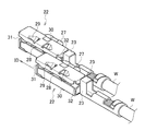
- FIG. 2 is an assembled perspective view showing the joint connector according to the embodiment of the present invention.
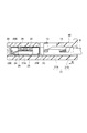
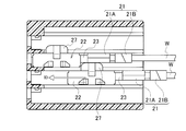
- FIG. 3 is a cross-sectional view showing the joint connector according to the embodiment of the present invention.
- FIG. 4A is a perspective view seen from the upper wall side of the joint terminal according to the embodiment of the present invention.
- FIG. 4B is a perspective view seen from the upper wall side of the joint terminal according to the embodiment of the present invention.
- FIG. 5A is a perspective view seen from the bottom wall side of the joint terminal according to the embodiment of the present invention.
- FIG. 5B is a perspective view seen from the bottom wall side of the joint terminal according to the embodiment of the present invention.
- FIG. 6 is a developed view showing the joint terminal according to the embodiment of the present invention.
- FIG. 7A is a diagram showing an assembly process of the joint connector according to the embodiment of the present invention.
- FIG. 7B is a diagram showing an assembly process of the joint connector according to the embodiment of the present invention.
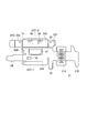
- FIG. 8A is a plan view showing the inside of the joint connector according to the embodiment of the present invention.
- FIG. 8B is a rear view showing the joint connector according to the embodiment of the present invention.
- FIG. 1 is an exploded perspective view showing a joint connector 1 according to the present embodiment.
- FIG. 2 is an assembled perspective view showing the joint connector according to the present embodiment.
- FIG. 3 is a cross-sectional view showing the joint connector 1 according to this embodiment.
- 4A and 4B and FIGS. 5A and 5B are perspective views showing the joint terminal 20 according to the present embodiment.
- FIG. 6 is a development view showing the joint terminal 20 according to the present embodiment.
- the joint connector 1 includes a connector housing 10 and a plurality of joint terminals 20 accommodated in the connector housing 10, and a plurality of joint terminals inserted into the connector housing 10. 20 are electrically connected.
- FIG. 1 and FIG. 2 only one joint terminal 20 is shown, but the other joint terminals 20 are omitted.
- the connector housing 10 is provided with a plurality of terminal accommodating chambers 12 each partitioned by a plurality of partition walls 11.
- Each partition wall 11 is formed with a communication groove 11 ⁇ / b> A (see FIG. 2) that allows the adjacent terminal accommodating chambers 12 to communicate with each other.
- the communication groove 11 ⁇ / b> A is provided at a position (upper surface side in the present embodiment) shifted from the center in the vertical direction of the terminal accommodating chamber 12.
- a plurality of lances 13 are integrally formed in the connector housing 10. Each lance 13 protrudes into the corresponding terminal accommodating chamber 12 so as to be displaceable.
- the joint terminal 20 is formed by bending a conductive plate having a predetermined shape shown in FIG.
- the joint terminal 20 includes an electric wire connection portion 21 to which an electric wire W (see FIGS. 2 and 3) is connected, a box-shaped terminal main body portion 22 provided integrally with the electric wire connection portion 21, and an electric wire of the terminal main body portion 22.
- a lance locking portion 23 provided on the connection portion 21 side and locked by the lance 13 is provided.
- the electric wire connecting portion 21 includes a core wire crimping portion 21A for caulking and fixing the core wire of the electric wire W and an insulating layer caulking portion 21B for caulking and fixing the insulating layer covering the core wire of the electric wire W.
- the wire connecting portion 21 is provided at a position shifted from the terminal main body portion 22 (close to a side wall 22B described later), and when the joint terminal 20 is inserted into the connector housing 10, the terminal main body portion 22 ( It does not come into contact with a male contact piece 27) to be described later.
- the terminal main body 22 is provided along the extending direction from the front end to the rear end of the terminal main body 22 (hereinafter, the insertion direction ID of the joint terminal 20 to the connector housing 10).
- the terminal body 22 includes a bottom wall 22A along the insertion direction ID of the joint terminal 20, a pair of side walls 22B and 22C (a first side wall surface and a second side wall surface), an upper wall 22D, and the joint terminal 20
- a front wall surface 22E and a rear wall surface 22F are provided along a direction intersecting the insertion direction ID.
- the bottom wall 22A is integrally formed with a cantilevered spring piece 24 that is folded back from the distal end side in the insertion direction ID of the joint terminal 20.
- the spring piece 24 is provided in the terminal main body portion 22 and constitutes a female side contact portion that contacts a terminal main body portion 22 (a male side contact piece 27 described later) of the adjacent joint terminal 20.
- the bottom wall 22A is formed with a convex portion 25 and an inclined piece 26 provided on the front side of the convex portion 25 with respect to the insertion direction ID of the joint terminal 20 to the connector housing 10.
- the convex portion 25 protrudes to a position corresponding to the thickness of the front end bottom surface 22G folded back from the front wall surface 22E, and ensures the balance of the joint terminal 20 in the connector housing 10.
- the inclined piece 26 prevents the tip bottom surface 22 ⁇ / b> G from being caught by the terminal accommodating chamber 12 when the joint terminal 20 is detached from the connector housing 10.
- the male side contact piece 27 protruding by being bent outward (horizontal direction) from the side wall 22B is provided on the side wall 22B.
- the male side contact piece 27 is provided at a position shifted from the center in the vertical direction of the side wall 22B so as to correspond to the position of the communication groove 11A (in this embodiment, the upper wall 22D side of the side wall 22C).
- the male contact piece 27 is inserted into the communication groove 11 ⁇ / b> A when the joint terminal 20 is attached to the connector housing 10.
- the side wall 22C faces the side wall 22B.
- the side wall 22C is formed by a bottom side wall 22C-1 bent from the bottom wall 22A and an upper side wall 22C-2 bent from the top wall 22D.
- the bottom side wall 22C-1 and the top side wall 22C-2 are spaced apart in the vertical direction.
- the female side slit 28 into which the male side contact piece 27 of the adjacent joint terminal 20 can be inserted is formed in the side wall 22C.
- the female slit 28 is formed on the side wall 22C so as to penetrate the terminal body 22 along the insertion direction ID.
- the female slit 28 is displaced from the vertical center of the side wall 22C so as to correspond to the position of the communication groove 11A (in this embodiment, the upper wall 22D of the side wall 22C).
- Both ends in the insertion direction ID of the female slit 28 are formed so as to gradually spread toward the outside (the front wall surface 22E or the rear wall surface 22F).
- the upper wall 22D is formed by being bent from the side wall 22B.
- the upper wall 22D is provided with contact portions 29 and 30 projecting inward of the terminal main body portion 22.
- the contact portions 29 and 30 are provided in the terminal main body portion 22 and constitute a female-side contact portion that comes into contact with the male-side contact piece 27 of the adjacent joint terminal 20.
- the male side contact piece 27 is inserted into the female side slit 28 of the terminal body portion 22 of the adjacent joint terminal 20 via the communication groove 11 ⁇ / b> A, and the adjacent joint terminal 20 is sandwiched between the spring piece 24 and the contact portions 29 and 30 as the female side contact portion.
- the adjacent terminal main-body parts 22, ie, the adjacent joint terminals 20 are electrically connected.
- the front wall surface 22E is provided at the distal end in the insertion direction ID and is formed by being bent from the upper wall 22D.
- the rear wall surface 22F is provided behind the front wall surface 22E with respect to the insertion direction ID, and is formed by being bent from the upper wall 22D.
- the front wall surface 22E and the rear wall surface 22F are formed with notches 31 and 32 that are formed at positions along the female slit 28 and through which the male contact piece 27 of the adjacent joint terminal 20 can pass. Yes.
- the notches 31 and 32 are formed corresponding to the positions of the male contact piece 27 and the female slit 28.
- the notches 31 and 32 are formed so as to open to the female slit 28 and gradually become narrower from the side wall 22C side toward the side wall 22B side.
- FIG. 8A is a plan view showing the inside of the joint connector 1 according to this embodiment
- FIG. 8B is a rear view showing the joint connector 1 according to this embodiment. 7A and 7B, the connector housing 10 is omitted.
- the joint terminals 20 are gradually inserted into the terminal housing chambers 12 of the connector housing 10. Then, the male side contact piece 27 passes through the communication groove 11 ⁇ / b> A and the notches 31 and 32 of the adjacent joint terminal 20 and is gradually inserted into the female side slit 28 of the terminal main body portion 22 of the adjacent joint terminal 20. .
- the adjacent joint terminals 20 are provided at positions where the wire connecting portions 21 of the adjacent joint terminals 20 are shifted from the terminal main body portion 22 (close to the side wall 22B).
- the male contact piece 27 is connected to the spring piece 24 and the contact portions 29 and 30 of the adjacent joint terminal 20. It is caught. Thereby, adjacent terminal main-body parts 22 (namely, adjacent joint terminals 20) are electrically connected. At this time, the female slit 28 is formed so as to penetrate the terminal body 22 along the insertion direction ID. For this reason, the male side contact piece 27 is inserted from both sides of the front wall surface 22E side of the adjacent joint terminal 20 as shown in FIG. 7A or the rear wall surface 22F side of the adjacent joint terminal 20 as shown in FIG. 7B. It becomes possible.
- the wire connecting portion 21 is provided at a position shifted from the terminal main body portion 22 (close to the side wall 22B). Thereby, it can prevent that the male side contact piece 27 contacts the electric wire connection part 21 of the adjacent joint terminal 20 at the time of insertion of the male side contact piece 27 to the female side slit 28 of the adjacent joint terminal 20. For this reason, when the male contact piece 27 is inserted into the female slit 28 of the adjacent joint terminal 20, the connection work between the adjacent joint terminals 20 can be performed without the electric wire connection portion 21 of the adjacent joint terminal 20 being in the way. It becomes easy.
- the female slit 28 is formed so as to penetrate the terminal body 22. Thereby, when inserting the male side contact piece 27 into the female side slit 28 of the adjacent joint terminal 20, it can be inserted and attached from both the front and rear ends of the terminal body portion 22 of the adjacent joint terminal 20. It becomes. For this reason, the connection procedure of adjacent joint terminals 20 becomes easy, without a restriction
- the embodiment of the present invention can be modified as follows.
- the shape and the like of the joint connector 1 are not limited to those described in the embodiment, and can be set as appropriate. That is, it is needless to say that the shape of the connector housing 10 and the joint terminal 20 can be set as appropriate.
- the communication groove 11A is not necessarily provided at a position shifted from the center of the terminal accommodating chamber 12 to the upper surface side, and may be formed at the center of the terminal accommodating chamber 12 or a position shifted from the center to the lower surface side. Good.
- the male contact piece 27, the female slit 28, and the notches 31, 32 may be formed corresponding to the position of the communication groove 11A.
- the electric wire connecting portion 21 is not necessarily provided at a position shifted to the side wall 22B side, and may be provided at a position shifted to the bottom wall 22A side or the upper wall 22D side, for example.
Landscapes
- Connector Housings Or Holding Contact Members (AREA)
- Details Of Connecting Devices For Male And Female Coupling (AREA)
- Coupling Device And Connection With Printed Circuit (AREA)
Description
まず、本実施形態に係るジョイントコネクタ1の構成について、図面を参照しながら説明する。図1は、本実施形態に係るジョイントコネクタ1を示す分解斜視図である。図2は、本実施形態に係るジョイントコネクタを示す組立斜視図である。図3は、本実施形態に係るジョイントコネクタ1を示す断面図である。図4A,4B及び図5A,5Bは、本実施形態に係るジョイント端子20を示す斜視図である。図6は、本実施形態に係るジョイント端子20を示す展開図である。
次に、上述したジョイントコネクタ1の組立方法について、図面を参照しながら簡単に説明する。図7A,7Bは、本実施形態に係るジョイントコネクタ1の組立過程を示す図である。図8Aは、本実施形態に係るジョイントコネクタ1内を示す平面図であり、図8Bは、本実施形態に係るジョイントコネクタ1を示す背面図である。なお、図7A,7Bでは、コネクタハウジング10は省略されている。
以上説明した本実施形態では、電線接続部21は、端子本体部22に対してずれた位置(側壁22B寄り)に設けられる。これにより、隣接するジョイント端子20のメス側スリット28へのオス側接触片27の挿入時に、オス側接触片27が隣接するジョイント端子20の電線接続部21に接触することを防止できる。このため、隣接するジョイント端子20のメス側スリット28へのオス側接触片27の挿入時に隣接するジョイント端子20の電線接続部21が邪魔になることなく、隣接するジョイント端子20同士の接続作業が容易となる。
上述したように、本発明の実施形態を通じて本発明の内容を開示したが、この開示の一部をなす論述及び図面は、本発明を限定するものであると理解すべきではない。この開示から当業者には様々な代替実施の形態、実施例及び運用技術が明らかとなる。
10…コネクタハウジング
11…仕切壁
11A…連通溝
12…端子収容室
20…ジョイント端子
21…電線接続部
22…端子本体部
22A…底壁
22B…側壁(第1の側壁面)
22C…側壁(第2の側壁面)
22C-1…底側壁
22C-2…上側壁
22D…上壁
22E…前壁面
22F…後壁面
22G…先端底面
23…ランス係止部
24…バネ片
25…凸部
26…傾斜片
27…オス側接触片
28…メス側スリット
29,30…接点部
31,32…切り欠き
W…電線
Claims (2)
- 隣接するジョイント端子と電気的に接続されるジョイント端子であって、
電線が接続される電線接続部と、
前記電線接続部に連結される端子本体部と、
を備え、
前記端子本体部は、前記隣接するジョイント端子の端子本体部に接触し、
前記電線接続部は、前記端子本体部に対してずれた位置に設けられることを特徴とするジョイント端子。 - 前記端子本体部は、
前記端子本体部の先端から後端に向かう延在方向に沿って設けられ、外方に向かって突出するオス側接触片(が形成される第1の側壁面と、
前記第1の側壁面と対向し、前記隣接するジョイント端子のオス側接触片が挿入可能なメス側スリットが形成される第2の側壁面と、
を備え、
前記電線接続部は、前記第1の側壁面寄りにずれていることを特徴とする請求項1に記載のジョイント端子。
Priority Applications (4)
| Application Number | Priority Date | Filing Date | Title |
|---|---|---|---|
| DE201311003365 DE112013003365T5 (de) | 2012-07-03 | 2013-06-26 | Verbundanschluss |
| CN201380035186.8A CN104412467A (zh) | 2012-07-03 | 2013-06-26 | 结合端子 |
| KR20157001618A KR20150027232A (ko) | 2012-07-03 | 2013-06-26 | 조인트 단자 |
| US14/583,246 US20150111444A1 (en) | 2012-07-03 | 2014-12-26 | Joint terminal |
Applications Claiming Priority (2)
| Application Number | Priority Date | Filing Date | Title |
|---|---|---|---|
| JP2012149400A JP5890265B2 (ja) | 2012-07-03 | 2012-07-03 | ジョイント端子 |
| JP2012-149400 | 2012-07-03 |
Related Child Applications (1)
| Application Number | Title | Priority Date | Filing Date |
|---|---|---|---|
| US14/583,246 Continuation US20150111444A1 (en) | 2012-07-03 | 2014-12-26 | Joint terminal |
Publications (1)
| Publication Number | Publication Date |
|---|---|
| WO2014007126A1 true WO2014007126A1 (ja) | 2014-01-09 |
Family
ID=49881883
Family Applications (1)
| Application Number | Title | Priority Date | Filing Date |
|---|---|---|---|
| PCT/JP2013/067539 Ceased WO2014007126A1 (ja) | 2012-07-03 | 2013-06-26 | ジョイント端子 |
Country Status (6)
| Country | Link |
|---|---|
| US (1) | US20150111444A1 (ja) |
| JP (1) | JP5890265B2 (ja) |
| KR (1) | KR20150027232A (ja) |
| CN (1) | CN104412467A (ja) |
| DE (1) | DE112013003365T5 (ja) |
| WO (1) | WO2014007126A1 (ja) |
Cited By (2)
| Publication number | Priority date | Publication date | Assignee | Title |
|---|---|---|---|---|
| EP4311036A3 (en) * | 2019-08-29 | 2024-05-01 | J.S.T. Corporation | An electrical male terminal, and methods for connecting thereof |
| JP7563347B2 (ja) | 2021-09-15 | 2024-10-08 | 株式会社オートネットワーク技術研究所 | 端子金具の接続構造及びジョイントコネクタ |
Families Citing this family (3)
| Publication number | Priority date | Publication date | Assignee | Title |
|---|---|---|---|---|
| JP2013168301A (ja) * | 2012-02-16 | 2013-08-29 | Yazaki Corp | ジョイントコネクタ |
| JP2024515903A (ja) * | 2021-06-21 | 2024-04-11 | ジェイ.エス.ティー.コーポレーション | 電気オス端子 |
| WO2022271210A1 (en) * | 2021-06-21 | 2022-12-29 | J.S.T. Corporation | An electrical male terminal |
Citations (5)
| Publication number | Priority date | Publication date | Assignee | Title |
|---|---|---|---|---|
| JPS6168487U (ja) * | 1984-10-12 | 1986-05-10 | ||
| JP2002075515A (ja) * | 2000-08-24 | 2002-03-15 | Sumitomo Wiring Syst Ltd | 端子金具及びジョイントコネクタ |
| JP2002124333A (ja) * | 2000-10-18 | 2002-04-26 | Sumitomo Wiring Syst Ltd | ジョイントコネクタ |
| JP2006108052A (ja) * | 2004-10-08 | 2006-04-20 | Fujikura Ltd | ジョイントコネクタ用端子金具 |
| JP2007087808A (ja) * | 2005-09-22 | 2007-04-05 | Union Machinery Co Ltd | 接続端子 |
Family Cites Families (7)
| Publication number | Priority date | Publication date | Assignee | Title |
|---|---|---|---|---|
| US4061406A (en) * | 1974-08-28 | 1977-12-06 | Amp Incorporated | High current carrying connector |
| JPH0740303Y2 (ja) * | 1990-03-13 | 1995-09-13 | 住友電装株式会社 | 電気接続子とそれを用いるコネクタ |
| US5558531A (en) * | 1994-02-09 | 1996-09-24 | Yazaki Corporation | Combination terminal |
| JP2954839B2 (ja) * | 1994-10-27 | 1999-09-27 | 矢崎総業株式会社 | 連鎖型接続端子およびその製造方法 |
| JP3317174B2 (ja) * | 1997-01-23 | 2002-08-26 | 住友電装株式会社 | アースジョイントコネクタ |
| JP3638840B2 (ja) * | 1999-12-02 | 2005-04-13 | 矢崎総業株式会社 | コネクタの接続方法 |
| US9054430B2 (en) * | 2012-07-02 | 2015-06-09 | Yazaki Corporation | Connection terminal |
-
2012
- 2012-07-03 JP JP2012149400A patent/JP5890265B2/ja not_active Expired - Fee Related
-
2013
- 2013-06-26 WO PCT/JP2013/067539 patent/WO2014007126A1/ja not_active Ceased
- 2013-06-26 DE DE201311003365 patent/DE112013003365T5/de not_active Withdrawn
- 2013-06-26 KR KR20157001618A patent/KR20150027232A/ko not_active Abandoned
- 2013-06-26 CN CN201380035186.8A patent/CN104412467A/zh active Pending
-
2014
- 2014-12-26 US US14/583,246 patent/US20150111444A1/en not_active Abandoned
Patent Citations (5)
| Publication number | Priority date | Publication date | Assignee | Title |
|---|---|---|---|---|
| JPS6168487U (ja) * | 1984-10-12 | 1986-05-10 | ||
| JP2002075515A (ja) * | 2000-08-24 | 2002-03-15 | Sumitomo Wiring Syst Ltd | 端子金具及びジョイントコネクタ |
| JP2002124333A (ja) * | 2000-10-18 | 2002-04-26 | Sumitomo Wiring Syst Ltd | ジョイントコネクタ |
| JP2006108052A (ja) * | 2004-10-08 | 2006-04-20 | Fujikura Ltd | ジョイントコネクタ用端子金具 |
| JP2007087808A (ja) * | 2005-09-22 | 2007-04-05 | Union Machinery Co Ltd | 接続端子 |
Cited By (2)
| Publication number | Priority date | Publication date | Assignee | Title |
|---|---|---|---|---|
| EP4311036A3 (en) * | 2019-08-29 | 2024-05-01 | J.S.T. Corporation | An electrical male terminal, and methods for connecting thereof |
| JP7563347B2 (ja) | 2021-09-15 | 2024-10-08 | 株式会社オートネットワーク技術研究所 | 端子金具の接続構造及びジョイントコネクタ |
Also Published As
| Publication number | Publication date |
|---|---|
| JP2014011145A (ja) | 2014-01-20 |
| DE112013003365T5 (de) | 2015-03-19 |
| KR20150027232A (ko) | 2015-03-11 |
| US20150111444A1 (en) | 2015-04-23 |
| CN104412467A (zh) | 2015-03-11 |
| JP5890265B2 (ja) | 2016-03-22 |
Similar Documents
| Publication | Publication Date | Title |
|---|---|---|
| JP2018018703A (ja) | コネクタ | |
| WO2018163788A1 (ja) | シールド端子及びシールドコネクタ | |
| JP6894877B2 (ja) | 防水コネクタ | |
| JP5890265B2 (ja) | ジョイント端子 | |
| WO2011074653A1 (ja) | ヒューズ用端子 | |
| JP6085527B2 (ja) | 雌端子 | |
| JP2014011148A (ja) | コネクタ | |
| WO2019124035A1 (ja) | シールド端子 | |
| JP2019145275A (ja) | コネクタ組立体 | |
| JP6812917B2 (ja) | 端子金具 | |
| JP6183665B2 (ja) | 端子 | |
| WO2014007051A1 (ja) | コネクタおよび接続端子 | |
| JP6431277B2 (ja) | コネクタ | |
| JP5890266B2 (ja) | ジョイント端子 | |
| JP2014011142A (ja) | ジョイントコネクタ | |
| JP5986933B2 (ja) | 端子 | |
| JP3175505U (ja) | ケーブル用コネクタ | |
| JP2013026127A (ja) | 嵌合検知構造 | |
| JP2014011144A (ja) | ジョイント端子 | |
| JP2014011147A (ja) | ジョイント端子 | |
| JP2014011143A (ja) | ジョイント端子 | |
| JP2002075515A (ja) | 端子金具及びジョイントコネクタ | |
| JP6406705B2 (ja) | コンタクト、リセプタクル及びコネクタ | |
| JP6106379B2 (ja) | コネクタ | |
| JP5947656B2 (ja) | コネクタ |
Legal Events
| Date | Code | Title | Description |
|---|---|---|---|
| 121 | Ep: the epo has been informed by wipo that ep was designated in this application |
Ref document number: 13812653 Country of ref document: EP Kind code of ref document: A1 |
|
| WWE | Wipo information: entry into national phase |
Ref document number: 112013003365 Country of ref document: DE Ref document number: 1120130033658 Country of ref document: DE |
|
| ENP | Entry into the national phase |
Ref document number: 20157001618 Country of ref document: KR Kind code of ref document: A |
|
| 122 | Ep: pct application non-entry in european phase |
Ref document number: 13812653 Country of ref document: EP Kind code of ref document: A1 |