WO2014006986A1 - 自動車用内装部品の仮止め爪 - Google Patents
自動車用内装部品の仮止め爪 Download PDFInfo
- Publication number
- WO2014006986A1 WO2014006986A1 PCT/JP2013/063656 JP2013063656W WO2014006986A1 WO 2014006986 A1 WO2014006986 A1 WO 2014006986A1 JP 2013063656 W JP2013063656 W JP 2013063656W WO 2014006986 A1 WO2014006986 A1 WO 2014006986A1
- Authority
- WO
- WIPO (PCT)
- Prior art keywords
- temporary
- latching
- claw
- hole
- vehicle compartment
- Prior art date
- Legal status (The legal status is an assumption and is not a legal conclusion. Google has not performed a legal analysis and makes no representation as to the accuracy of the status listed.)
- Ceased
Links
Images



Classifications
-
- B—PERFORMING OPERATIONS; TRANSPORTING
- B60—VEHICLES IN GENERAL
- B60R—VEHICLES, VEHICLE FITTINGS, OR VEHICLE PARTS, NOT OTHERWISE PROVIDED FOR
- B60R21/00—Arrangements or fittings on vehicles for protecting or preventing injuries to occupants or pedestrians in case of accidents or other traffic risks
- B60R21/02—Occupant safety arrangements or fittings, e.g. crash pads
- B60R21/16—Inflatable occupant restraints or confinements designed to inflate upon impact or impending impact, e.g. air bags
- B60R21/20—Arrangements for storing inflatable members in their non-use or deflated condition; Arrangement or mounting of air bag modules or components
- B60R21/213—Arrangements for storing inflatable members in their non-use or deflated condition; Arrangement or mounting of air bag modules or components in vehicle roof frames or pillars
Definitions
- the present invention relates to a temporary fixing claw for temporarily fixing an automobile interior part to a vehicle compartment side mounting portion.
- a temporarily fixed state is once formed in order to improve workability.
- This temporarily fixed state is performed by providing a temporary fixing claw on a bracket or the like for holding the interior part and hooking the temporary fixing claw into a locking hole provided in the body or the like.
- an invitation hole is provided in one of the bracket fixed to one surface of the room and the device main body attached to the bracket, and the other is fitted into the invitation hole. Possible temporary holding hooks are provided.
- a positioning hole is provided in one of the bracket and the apparatus main body, and a positioning rib that fits into the positioning hole and matches the screw position is provided in the other.
- the positioning rib is naturally drawn into the positioning hole of the bracket, and the screw tightening positions of the device main body and the bracket are naturally determined. Thereby, the attachment work to a vehicle is made easy.
- a claw-shaped portion is provided on the receiving surface portion of the audio installation portion of the instrument panel, and the receiving surface portion and the mounting surface portion are provided on the mounting surface portion of the mounting bracket.
- a claw locking portion capable of locking the claw-shaped portion in the contact state is provided.
- a hooking portion of the temporary fixing nail (temporary holding hook, nail shape portion) is provided so as to protrude only in one direction of the temporary fixing nail. .
- the temporarily fixed claw will rise from the retaining hole and the temporary fixed state cannot be maintained.
- the interior part may be rotated. Therefore, further improvements are required to improve the difficulty of dropping off and ease of assembly.
- the present invention has been made in view of such a background, and improves the ease of insertion into a retaining hole, the difficulty of falling off from the retaining hole, and the ease of assembly of interior parts for automobiles. It was obtained in an attempt to provide a temporary fastening claw for an automotive interior part.
- One aspect of the present invention is a temporary fastening claw for temporarily fastening an interior part for an automobile to a vehicle compartment side mounting portion
- the temporary pawl is made of a plate material, and a plurality of the projections are provided so as to protrude from the automobile interior part, and the plate material is orthogonal to the surface of the vehicle compartment side attachment portion, and the vehicle compartment side attachment portion It is configured to be inserted into the retaining hole provided in the And the said temporary stop nail
- claw has a base part which has a pair of side surface arrange
- the temporary fixing claws of the automobile interior parts are made of a plate material, and the performance of temporary fixing is improved by devising the shape.
- a plurality of temporary fastening claws are provided so as to protrude from the interior parts for automobiles, and are inserted into the retaining holes provided in the vehicle compartment side mounting portion with the plate material orthogonal to the surface of the vehicle compartment side mounting portion.
- the planar shape of the plate material constituting each temporary fastening pawl has a base, one inclined portion, one hanging portion, the other hanging portion, the other inclined portion, and an insertion tip portion, so that It is possible to improve the ease of insertion, the difficulty of falling off from the retaining holes, and the ease of assembly.
- each temporary retaining pawl When inserting each temporary retaining pawl into each retaining hole, first the insertion tip is inserted into the retaining hole, and then the temporary retaining pawl is centered in the retaining hole by the other inclined portion and one inclined portion. To be guided to. Thereby, the temporary fixing claw can be easily guided to the center position of the latching hole, and the automobile interior part can be easily mounted on the vehicle compartment side mounting portion. Therefore, it is possible to improve the ease of insertion of the temporary fastening claws into the retaining holes.
- the interior parts for automobiles in a temporarily fixed state are finally tightened to the vehicle compartment side mounting portion using a fixture.
- the gap between the pair of side surfaces and the latching hole in the base is set as small as possible by the configuration of the temporary latching claw provided with the one inclined portion, the one latching portion, the other tilting portion, and the other latching portion.
- claw is naturally guided to the inner wall face of each latching hole.
- the interior parts for automobiles in the temporarily fixed state are easily arranged at the normal positions with respect to the vehicle interior side mounting portion by the guidance of the temporary fixing claws.
- the interior part for automobile can be made difficult to rotate because the gap between the pair of side surfaces and the retaining hole in the base is small. Therefore, the ease of assembling the automobile interior parts can be improved.
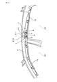
- claw of the interior component for motor vehicles concerning an Example The perspective view which shows the state which temporarily fixes the interior component for motor vehicles concerning the Example to the compartment side attachment part.
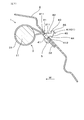
- Sectional drawing which shows the state which fastened the interior component for motor vehicles concerning the Example to the compartment side attachment part.
- Explanatory drawing which expands and shows the temporary fix
- Sectional drawing which shows the state by which the 1st latching part concerning an Example is latched by the latching hole of a compartment side attachment part, and the interior part for motor vehicles is temporarily latched by the compartment side attachment part.
- Sectional drawing which shows the state which the 2nd latching
- the inside of the plane of the plate means the other side of the pair of side surfaces in one of the pair of side surfaces of the base, and the other of the pair of side surfaces of the base In, it means one side of a pair of side surfaces.
- the outside of the plane of the plate means the side away from the other of the pair of side surfaces in one of the pair of side surfaces in the base portion, and one of the pair of side surfaces in the other of the pair of side surfaces in the base portion.
- the inside of the flat surface of the plate material can be referred to as the inside of the temporary fastening claw, and the outside of the flat surface of the plate material can be referred to as the outside of the temporary fastening claw.
- the plate material constituting the temporary fastening claws can be formed into a shape in which, for example, the one hooking portion, the other hooking portion, etc. are partially raised from the flat plate, in addition to a complete flat plate shape.
- the automotive interior component includes a component main body and a bracket that holds the component main body and is attached to the vehicle compartment side mounting portion.
- the bracket includes the plurality of temporary fixing claws, An insertion hole for inserting a screw as the fixing tool to be tightened to the vehicle compartment side mounting portion may be provided.
- the provisional claw can be easily formed, and the automobile interior part can be easily fastened to the vehicle compartment side mounting portion with the screw inserted through the insertion hole.
- claw may protrude vertically from the back surface of the said bracket in the state in which the said one inclination part and the said one latching part are located in the perpendicular direction upper side.
- the rigidity of the temporary fixing claw itself can be easily ensured.
- a plurality of the temporary fastening claws are provided in the automotive interior part in a state where the planes of the plate members are parallel to each other and are aligned in the horizontal direction, and the temporary fastening state of the automotive interior part is provided.
- the one latching portion or the other latching portion of the plurality of temporary latching claws is latched in the latching hole. It may be configured to be.
- a plurality of temporary fastening claws are arranged in the horizontal direction, and the lower end of the bracket is in contact with the vehicle compartment side attachment portion, whereby the automobile interior part is temporarily attached to the vehicle compartment side attachment portion. Can be maintained more stably.
- the automobile interior part may be an inflator of a curtain shield airbag provided in a window portion of the automobile.
- inflator it is possible to improve the ease of insertion of the temporary retaining claws into the retaining holes, the difficulty of falling off the retaining holes, and the ease of assembly.
- the temporary fastening claws 4 of the automotive interior part 1 are for temporarily fastening the automotive interior part 1 to the vehicle compartment side mounting portion 21 as shown in FIGS.
- the temporary fastening claws 4 are made of a plate material, and a plurality of temporary fastening claws 4 are provided so as to protrude from the automotive interior part 1. Further, the temporary fastening claws 4 are configured to be inserted into the latching holes 211 provided in the vehicle compartment side attachment portion 21 with the plate material orthogonal to the surface of the vehicle compartment side attachment portion 21.
- the temporary pawl 4 has the following base portion 41, one inclined portion 42, one hanging portion 43, the other hanging portion 44, the other inclined portion 45, and the insertion in the planar shape of the plate material. It has a tip 46.
- the base 41 has a pair of side surfaces 411 and 412 that are arranged along the inner wall surface of the retaining hole 211 when the automobile interior part 1 is finally fastened to the vehicle compartment side mounting portion 21 with a fixture. .
- the inclined portion 42 is bent from one side surface 411 to the inside of the plane of the plate material in a state where an obtuse angle ⁇ 1 is formed between the side surface 411 of the base portion 41 (one of the pair of side surfaces 411 and 412), This is a portion that guides the insertion into the retaining hole 211.
- the one latching portion 43 is a portion that can be bent from the one inclined portion 42 to the outside of the plane of the plate member and latched in the latching hole 211 (see FIG. 5).
- the other latching portion 44 is a portion that can be bent from the other side surface 412 (the other of the pair of side surfaces 411 and 412) of the base portion 41 to the outside of the plane of the plate and latched in the latching hole 211 (FIG. 6). reference).
- the other inclined portion 45 is a portion that bends inward from the other engaging portion 44 to the inside of the plane of the plate material in a state where an acute angle ⁇ 4 is formed between the other engaging portion 44 and guides the insertion into the engaging hole 211. It is.
- the insertion tip portion 46 is a portion that connects the other inclined portion 45 and the one latching portion 43.
- FIG. 3 shows a state 401 in which the base portion 41 of the temporary fastening pawl 4 is positioned in the retaining hole 211 and the automotive interior part 1 is finally tightened to the vehicle compartment side mounting portion 21 by the screw 5 as a fixture.
- FIG. 5 shows a state 402 in which the one latching portion 43 of the temporary latching claw 4 is latched in the latching hole 211
- FIG. 6 shows the other latching portion 44 of the temporary latching claw 4 in the latching hole 211.
- a state 403 to be hooked is shown.
- the automotive interior part 1 of this example is an inflator 1 of a curtain shield airbag 12 provided in a window portion of the automobile.
- the curtain shield airbag 12 is disposed on the upper portion of the door sash 2 in the side door of the automobile.
- the curtain shield airbag 12 can cover the surface of the window glass 22 in a door at the time of the collision of a motor vehicle, and can protect the passenger
- the inflator 1 generates gas at the time of a collision of the automobile, and sends the gas to the curtain shield airbag 12 to inflate the curtain shield airbag 12.
- the inflator 1 is attached to an intermediate position in the front-rear direction so as to send gas to the curtain shield airbag 12 on the front side and the curtain shield airbag 12 on the rear side.
- the vehicle compartment side mounting portion 21 of this example is provided on the door sash 2 as a part of the body of the automobile.
- the inflator 1 is attached to the door sash 2 by a plurality of temporary fixing claws 4 and screws 5 as fixing tools.
- the door sash 2 is provided with a plurality of retaining holes 211 for retaining the temporary retaining claws 4.
- the inflator 1 includes a component main body 11 and a bracket 3 that holds the component main body 11 and is attached to the vehicle compartment side attachment portion 21.
- the bracket 3 is attached at two locations on the inflator 1 on the front side and the rear side.
- the bracket 3 is formed so as to protrude vertically from the outer peripheral portion 31 that is wound around the outer periphery of the cylindrical inflator 1, the mounting plate portion 32 that protrudes from the outer peripheral portion 31, and the rear surface of the mounting plate portion 32. And temporary fixing claws 4. Further, the attachment plate portion 32 is provided with an insertion hole 321 through which the screw 5 to be fastened to the vehicle compartment side attachment portion 21 is inserted.
- the bracket 3 is made of metal, and the temporary fixing claw 4 is formed by bending vertically from the mounting plate portion 32 as a metal claw.
- the temporary fastening claws 4 in each bracket 3 are provided so as to protrude vertically from the back surface of the mounting plate portion 32 in a state where the one inclined portion 42 and the one hooking portion 43 are positioned on the upper side in the vertical direction.
- the temporary fixing claw 4 is provided on one side of the mounting plate portion 32.
- the latching holes 211 formed in the vehicle compartment side attachment portion 21 of the door sash 2 are provided at two locations aligned in the horizontal direction facing the position of the bracket 3 attached before and after the inflator 1. ing. Further, a screw hole 212 into which the screw 5 inserted through the insertion hole 321 is screwed is provided at a position adjacent to the retaining hole 211 in the passenger compartment side attachment portion 21.
- the temporary fixing claws 4 in each bracket 3 are arranged on the inflator 1 in a state where the planes of the plate materials are parallel to each other while being parallel to each other.
- the mounting plate portion 32 of each bracket 3 is formed to protrude obliquely downward from the outer peripheral portion 31 wound around the inflator 1.
- each bracket 3 is in a state in which the lower end portion 33 of the mounting plate portion 32 of each bracket 3 is in contact with the vehicle compartment side mounting portion 21.
- the one latching portion 43 or the other latching portion 44 of the three temporary latching claws 4 is configured to be latched by the latching hole 211.
- the vehicle compartment side mounting portion 21 of the door sash 2 is formed so as to be inclined toward the indoor side (center side in the left-right direction of the automobile) W as it goes upward.
- the inflator 1 is temporarily fixed to the vehicle compartment side mounting portion 21 by the temporary fixing claws 4, as shown in FIGS. 5 and 6, when the inflator 1 hangs down by its own weight, the mounting plate portion 32 of each bracket 3 is used.
- the lower end portion 33 of the vehicle is in contact with the vehicle compartment side mounting portion 21 so that the temporarily fixed state of the inflator 1 is maintained.
- the width between the upper and lower inner wall surfaces of the retaining hole 211 is formed to be almost the same as the width between the pair of side surfaces 411, 412 in the base 41 of the temporary fixing claw 4.
- the width between the upper and lower inner wall surfaces of the retaining hole 211 is between the pair of side surfaces 411 and 412 in the base 41 of the temporary retaining pawl 4 so that the base 41 can be inserted into the retaining hole 211. It is formed 0.2 mm larger than the width.
- the width between the upper and lower inner wall surfaces of the retaining hole 211 can be formed to be 0.1 to 1 mm larger than the width between the pair of side surfaces 411 and 412 in the base portion 41 of the temporary retaining claw 4.
- the base portion 41 is formed such that a pair of side surfaces 411 and 412 are perpendicular to the mounting plate portion 32.
- the inclined portion 42 is bent from one side surface 411 in a state of forming a mountain shape 421 having an obtuse angle ⁇ 1 of 90 ° or more and less than 180 ° (actually 110 ° or more and less than 160 °) between the one side surface 411. It is formed as a surface to do.
- the inclined portion 42 is formed so as to be inclined with respect to the one side surface 411 toward the inner side of the plane of the plate, which is the side from the one side surface 411 toward the other side surface 412 as it goes to the front end side. Yes.
- the one latching portion 43 is inclined in one direction toward the outside of the flat surface of the plate material, which is the side toward the outside of the one side surface 411 in a state where an acute angle is formed with the surface forming the one inclined portion 42. It is formed by folding back to the portion 42.
- the one latching portion 43 is in a state in which a valley shape 431 having an acute angle ⁇ 2 of 45 ° or more and less than 90 ° (actually 45 ° or more and less than 75 °) is formed between the one inclined portion 42 and the one inclined portion 42. It is formed as a surface that turns back to the surface.
- the other hooking portion 44 forms the valley shape 441 having an angle ⁇ 3 of approximately 90 ° (actually 70 ° or more and less than 100 °) with respect to the other side surface 412 in the other side surface 412. It is formed to bend to the other side surface 412 toward the outside of the flat surface of the plate, which is the side facing 412 outward.
- the corner (valley shape 441) between the other side surface 412 and the surface of the other hooking portion 44 in this example is formed in a shape that is recessed toward the inside of the plane of the plate material.
- the other inclined portion 45 forms a mountain shape 451 having an acute angle ⁇ 4 of 45 ° or more and less than 90 ° (actually 45 ° or more and less than 75 °) between the other hanging portion 44 and the other hanging portion 44. It is formed as a surface that bends.
- the other inclined portion 45 is formed to be inclined with respect to the other side surface 412 toward the inner side of the plane of the plate, which is the side from the other side surface 412 side toward the one side surface 411 side as it goes to the front end side.
- the insertion tip 46 is formed in a curved shape between the tip of the one latching portion 43 and the tip of the other inclined portion 45.
- the insertion tip portion 46 of this example is formed in a straight line shape from the tip end of the one latching portion 43 and then in a curved shape toward the tip end of the other inclined portion 45.
- the operation of attaching the inflator 1 to the vehicle compartment side attachment portion 21 of the door sash 2 and the operation and effect of the temporary fastening claws 4 will be described.
- two brackets 3 are attached to the inflator 1 in advance.
- the temporary attachment of the inflator 1 and the final tightening attachment operation with the screw 5 are performed manually by the operator.
- the inflator 1 can be attached using a machine such as an industrial robot.
- the operator When inserting the temporary retaining claws 4 in each bracket 3 into the respective retaining holes 211 of the vehicle compartment side attaching portion 21, the operator first inserts the respective insertion tips 46 into the respective retaining holes 211. At this time, the other inclined portion 45 comes into contact with the lower inner wall surface of the retaining hole 211, and the temporary retaining pawl 4 is guided to the center of the retaining hole 211. Further, when the temporary pawl 4 is further inserted into the hooking hole 211, the one inclined portion 42 comes into contact with the upper inner wall surface of the hooking hole 211, so that the temporary hooking pawl 4 is in the center of the hooking hole 211. To be guided to.
- pawl 4 can be easily guided to the center position of the latching hole 211, and the mounting
- the operator inserts the screw 5 into the insertion hole 321 in the attachment plate portion 32 of each bracket 3, and screws this screw 5 into the screw hole 212 in the vehicle compartment side attachment portion 21. .
- the inflator 1 in the temporarily fixed state is finally tightened to the vehicle compartment side attachment portion 21.
- a pair of side surfaces 411 and 412 and a hooking hole 211 in the base 41 are formed by the configuration of the temporary fastening claws 4 provided with the one inclined portion 42, the one hanging portion 43, the other inclined portion 45 and the other hanging portion 44. Can be set as small as possible.
- the inflator 1 When the inflator 1 is finally tightened, the pair of side surfaces 411 and 412 in the base portion 41 of each temporary fixing claw 4 are naturally guided to the inner wall surface of each retaining hole 211. Thereby, the inflator 1 in the temporarily fixed state is easily disposed at the normal position with respect to the vehicle compartment side mounting portion 21 by the guidance of the temporary fixing claws 4. Further, when the inflator 1 is finally tightened, the gap between the pair of side surfaces 411 and 412 and the hooking hole 211 in the base 41 is small, so that the inflator 1 can be made difficult to rotate. Therefore, the ease of assembly of the inflator 1 can be improved.
- the temporary fixing claw 4 of the inflator 1 of this example it is easy to insert into the retaining hole 211, it is difficult to drop off from the retaining hole 211, and to be easily assembled to the inflator 1. Can be improved.
Landscapes
- Engineering & Computer Science (AREA)
- Mechanical Engineering (AREA)
- Air Bags (AREA)
- Fittings On The Vehicle Exterior For Carrying Loads, And Devices For Holding Or Mounting Articles (AREA)
- Connection Of Plates (AREA)
Description
本発明は、自動車用内装部品を車室側取付部に仮止めするための仮止め爪に関する。
自動車の車室側に設けられる種々の内装部品においては、ネジによってボディ等に取り付ける際に、作業性を向上させるために、仮止め状態を一旦形成することが行われている。この仮止め状態は、内装部品を保持するブラケット等に仮止め爪を設け、この仮止め爪をボディ等に設けられた掛止穴に掛止することによって行われている。
例えば、特許文献1の電子機器の仮固定構造においては、室内の一面に固定されるブラケットと、ブラケットに取り付けられる機器本体とのいずれか一方に誘い穴を設け、他方に、誘い穴に嵌合可能な仮保持用フックを設けている。また、ブラケットと機器本体とのいずれか一方に、位置決め穴を設け、他方に、位置決め穴に嵌合してネジ位置を合わせる位置決めリブを設けている。そして、仮保持用フックで機器本体をブラケットに仮保持すると、位置決めリブがブラケットの位置決め穴に自然に誘い込まれ、機器本体とブラケットのネジ締め位置が自然に定まる。これにより、車両への取り付け作業を容易にしている。
例えば、特許文献1の電子機器の仮固定構造においては、室内の一面に固定されるブラケットと、ブラケットに取り付けられる機器本体とのいずれか一方に誘い穴を設け、他方に、誘い穴に嵌合可能な仮保持用フックを設けている。また、ブラケットと機器本体とのいずれか一方に、位置決め穴を設け、他方に、位置決め穴に嵌合してネジ位置を合わせる位置決めリブを設けている。そして、仮保持用フックで機器本体をブラケットに仮保持すると、位置決めリブがブラケットの位置決め穴に自然に誘い込まれ、機器本体とブラケットのネジ締め位置が自然に定まる。これにより、車両への取り付け作業を容易にしている。
また、例えば、特許文献2の車載用オーディオ装置取付構造においては、インストルメントパネルのオーディオ設置部の受面部に、爪形状部を設け、取付用ブラケットの取付面部に、受面部と取付面部との当接状態で爪形状部が係止可能な爪係止部を設けている。この爪形状部及び爪係止部の形成により、オーディオ装置を取付用ブラケットに確実に仮保持し得るようにしている。
しかしながら、従来の仮止め爪等を用いた仮止め構造においては、仮止め爪(仮保持用フック、爪形状部)における引掛け部分が、仮止め爪における一方向にしか突出して設けられていない。そのため、内装部品が自重により垂れ下がるか持ち上げられるときには、仮止め爪が掛止穴から浮き上がって、仮止め状態が維持できないおそれがある。また、ネジ締めを行って内装部品をボディ等に取り付ける際に、この内装部品が回転してしまうおそれがある。そのため、脱落のしにくさ、組付のしやすさ等を改善するには更なる工夫が必要とされる。
本発明は、かかる背景に鑑みてなされたもので、掛止穴への挿入のしやすさ、掛止穴からの脱落のしにくさ及び自動車用内装部品の組付のしやすさを向上させることができる自動車用内装部品の仮止め爪を提供しようとして得られたものである。
本発明の一態様は、自動車用内装部品を車室側取付部に仮止めするための仮止め爪であって、
該仮止め爪は、板材から構成され、上記自動車用内装部品から複数個が突出して設けられているとともに、上記板材を上記車室側取付部の表面に直交させて、該車室側取付部に設けられた掛止穴に挿入されるよう構成されており、
かつ、上記仮止め爪は、上記自動車用内装部品を固定具によって上記車室側取付部に本締めするときに、上記掛止穴の内壁面に沿って配置される一対の側面を有する基部と、
上記一対の側面の一方との間に鈍角を形成する状態で、該側面の一方から上記板材の平面の内側へ屈曲して、上記掛止穴への挿入を案内する一方傾斜部と、
該一方傾斜部から上記板材の平面の外側へ屈曲して、上記掛止穴に掛止可能な一方掛止部と、
上記一対の側面の他方から上記板材の平面の外側へ屈曲して、上記掛止穴に掛止可能な他方掛止部と、
該他方掛止部との間に鋭角を形成する状態で、該他方掛止部から上記板材の平面の内側へ屈曲して、上記掛止穴への挿入を案内する他方傾斜部と、
該他方側傾斜部と上記一方掛止部とを結ぶ挿入先端部と、を有していることを特徴とする自動車用内装部品の仮止め爪にある。
該仮止め爪は、板材から構成され、上記自動車用内装部品から複数個が突出して設けられているとともに、上記板材を上記車室側取付部の表面に直交させて、該車室側取付部に設けられた掛止穴に挿入されるよう構成されており、
かつ、上記仮止め爪は、上記自動車用内装部品を固定具によって上記車室側取付部に本締めするときに、上記掛止穴の内壁面に沿って配置される一対の側面を有する基部と、
上記一対の側面の一方との間に鈍角を形成する状態で、該側面の一方から上記板材の平面の内側へ屈曲して、上記掛止穴への挿入を案内する一方傾斜部と、
該一方傾斜部から上記板材の平面の外側へ屈曲して、上記掛止穴に掛止可能な一方掛止部と、
上記一対の側面の他方から上記板材の平面の外側へ屈曲して、上記掛止穴に掛止可能な他方掛止部と、
該他方掛止部との間に鋭角を形成する状態で、該他方掛止部から上記板材の平面の内側へ屈曲して、上記掛止穴への挿入を案内する他方傾斜部と、
該他方側傾斜部と上記一方掛止部とを結ぶ挿入先端部と、を有していることを特徴とする自動車用内装部品の仮止め爪にある。
上記自動車用内装部品の仮止め爪は、板材から構成されており、その形状に工夫をすることにより、仮止めの性能を向上させている。
仮止め爪は、自動車用内装部品から複数個が突出して設けられているとともに、板材を車室側取付部の表面に直交させて、車室側取付部に設けられた掛止穴に挿入されるものである。そして、各仮止め爪を構成する板材の平面形状が、基部、一方傾斜部、一方掛止部、他方掛止部、他方傾斜部及び挿入先端部を有していることにより、掛止穴への挿入のしやすさ、掛止穴からの脱落のしにくさ、組付のしやすさを向上させることができる。
仮止め爪は、自動車用内装部品から複数個が突出して設けられているとともに、板材を車室側取付部の表面に直交させて、車室側取付部に設けられた掛止穴に挿入されるものである。そして、各仮止め爪を構成する板材の平面形状が、基部、一方傾斜部、一方掛止部、他方掛止部、他方傾斜部及び挿入先端部を有していることにより、掛止穴への挿入のしやすさ、掛止穴からの脱落のしにくさ、組付のしやすさを向上させることができる。
各仮止め爪を各掛止穴に挿入する際には、まず、挿入先端部が掛止穴に挿入され、続いて、他方傾斜部及び一方傾斜部によって、仮止め爪が掛止穴の中心へ案内される。これにより、仮止め爪を掛止穴の中心位置へ容易に案内することができ、車室側取付部への自動車用内装部品の装着を容易に行うことができる。そのため、掛止穴への仮止め爪の挿入のしやすさを向上させることができる。
続いて、各仮止め爪が各掛止穴に挿入されたときには、自動車用内装部品が各仮止め爪によって車室側取付部に仮止めされる。このとき、自動車用内装部品が一方側へ位置ずれしようとするときには、一方掛止部が掛止穴に掛止され、自動車用内装部品が他方側へ位置ずれしようとするときには、他方掛止部が掛止穴に掛止される。これにより、複数の仮止め爪によって、車室側取付部に対する自動車用内装部品の仮止め状態を安定して維持することができる。そのため、掛止穴からの仮止め爪の脱落のしにくさを向上させることができる。
続いて、固定具を用いて、仮止め状態の自動車用内装部品を車室側取付部に本締めする。ここで、一方傾斜部、一方掛止部、他方傾斜部及び他方掛止部を設けた仮止め爪の構成により、基部における一対の側面と掛止穴との間の隙間を極力小さく設定することができる。そして、自動車用内装部品の本締めを行うときには、各仮止め爪の基部における一対の側面が各掛止穴の内壁面に自然と導かれる。これにより、仮止め状態の自動車用内装部品は、各仮止め爪の案内によって、車室側取付部に対する正規位置に容易に配置される。また、自動車用内装部品の本締めを行う際に、基部における一対の側面と掛止穴との間の隙間が小さいことにより、この自動車用内装部品が回転しにくくすることができる。そのため、自動車用内装部品の組付のしやすさを向上させることができる。
それ故、上記自動車用内装部品の仮止め爪によれば、掛止穴への挿入のしやすさ、掛止穴からの脱落のしにくさ及び自動車用内装部品の組付のしやすさを向上させることができる。
上述した自動車用内装部品の仮止め爪における好ましい実施の形態につき説明する。
上記自動車用内装部品の仮止め爪において、上記板材の平面の内側とは、上記基部における一対の側面の一方においては、一対の側面の他方の側を意味し、上記基部における一対の側面の他方においては、一対の側面の一方の側を意味する。また、上記板材の平面の外側とは、上記基部における一対の側面の一方においては、一対の側面の他方から離れる側を意味し、上記基部における一対の側面の他方においては、一対の側面の一方から離れる側を意味する。上記板材の平面の内側は、仮止め爪の内方ということができ、上記板材の平面の外側は、仮止め爪の外方ということができる。
また、上記仮止め爪を構成する板材は、完全な平板形状とする以外にも、例えば上記一方掛止部、上記他方掛止部等が部分的に平板から起立する形状とすることもできる。
上記自動車用内装部品の仮止め爪において、上記板材の平面の内側とは、上記基部における一対の側面の一方においては、一対の側面の他方の側を意味し、上記基部における一対の側面の他方においては、一対の側面の一方の側を意味する。また、上記板材の平面の外側とは、上記基部における一対の側面の一方においては、一対の側面の他方から離れる側を意味し、上記基部における一対の側面の他方においては、一対の側面の一方から離れる側を意味する。上記板材の平面の内側は、仮止め爪の内方ということができ、上記板材の平面の外側は、仮止め爪の外方ということができる。
また、上記仮止め爪を構成する板材は、完全な平板形状とする以外にも、例えば上記一方掛止部、上記他方掛止部等が部分的に平板から起立する形状とすることもできる。
また、上記自動車用内装部品は、部品本体と、該部品本体を保持して上記車室側取付部に取り付けられるブラケットとを有しており、該ブラケットには、上記複数の仮止め爪と、上記車室側取付部に締め付ける上記固定具としてのビスを挿通する挿通穴とが設けられていてもよい。
この場合には、仮止め爪の形成が容易であり、挿通穴に挿通したビスによって自動車用内装部品を車室側取付部に容易に本締めすることができる。また、ブラケットを用いることにより、仮止め爪及び挿通穴の形成が容易になる。
この場合には、仮止め爪の形成が容易であり、挿通穴に挿通したビスによって自動車用内装部品を車室側取付部に容易に本締めすることができる。また、ブラケットを用いることにより、仮止め爪及び挿通穴の形成が容易になる。
また、上記仮止め爪は、上記一方傾斜部及び上記一方掛止部が鉛直方向上側に位置する状態で、上記ブラケットの裏面から垂直に突出して設けられていてもよい。
この場合には、仮止め爪自体の剛性を容易に確保することができる。また、一方掛止部及び他方掛止部によって各仮止め爪が各掛止穴から脱落しにくい状態を容易に形成することができる。
この場合には、仮止め爪自体の剛性を容易に確保することができる。また、一方掛止部及び他方掛止部によって各仮止め爪が各掛止穴から脱落しにくい状態を容易に形成することができる。
また、上記仮止め爪は、上記板材の平面が互いに対向して平行になるとともに水平方向に並ぶ状態で複数個が上記自動車用内装部品に設けられており、上記自動車用内装部品の仮止め状態を形成するときには、上記ブラケットの下端部が上記車室側取付部に当接した状態で、上記複数の仮止め爪における上記一方掛止部又は上記他方掛止部が上記掛止穴に掛止されるよう構成されていてもよい。
この場合には、複数の仮止め爪が水平方向に並び、かつブラケットの下端部が車室側取付部に当接することにより、自動車用内装部品が車室側取付部に仮止めされる状態を、より安定して維持することができる。
この場合には、複数の仮止め爪が水平方向に並び、かつブラケットの下端部が車室側取付部に当接することにより、自動車用内装部品が車室側取付部に仮止めされる状態を、より安定して維持することができる。
また、上記自動車用内装部品は、自動車の窓部に設けられるカーテンシールドエアバッグのインフレータであってもよい。
この場合には、インフレータにおいて、仮止め爪の掛止穴への挿入のしやすさ、掛止穴からの脱落のしにくさ及び組付のしやすさを向上させることができる。
この場合には、インフレータにおいて、仮止め爪の掛止穴への挿入のしやすさ、掛止穴からの脱落のしにくさ及び組付のしやすさを向上させることができる。
以下に、自動車用内装部品の仮止め爪にかかる実施例につき、図面を参照して説明する。
自動車用内装部品1の仮止め爪4は、図1~図3に示すごとく、自動車用内装部品1を車室側取付部21に仮止めするためのものである。
仮止め爪4は、板材から構成され、自動車用内装部品1から複数個が突出して設けられている。また、仮止め爪4は、板材を車室側取付部21の表面に直交させて、車室側取付部21に設けられた掛止穴211に挿入されるよう構成されている。
自動車用内装部品1の仮止め爪4は、図1~図3に示すごとく、自動車用内装部品1を車室側取付部21に仮止めするためのものである。
仮止め爪4は、板材から構成され、自動車用内装部品1から複数個が突出して設けられている。また、仮止め爪4は、板材を車室側取付部21の表面に直交させて、車室側取付部21に設けられた掛止穴211に挿入されるよう構成されている。
仮止め爪4は、図3、図4に示すごとく、その板材の平面形状において、次の基部41、一方傾斜部42、一方掛止部43、他方掛止部44、他方傾斜部45及び挿入先端部46を有している。
基部41は、自動車用内装部品1を固定具によって車室側取付部21に本締めするときに、掛止穴211の内壁面に沿って配置される一対の側面411,412を有している。一方傾斜部42は、基部41の一方の側面411(一対の側面411,412の一方)との間に鈍角θ1を形成する状態で、一方の側面411から板材の平面の内側へ屈曲して、掛止穴211への挿入を案内する部分である。一方掛止部43は、一方傾斜部42から板材の平面の外側へ屈曲して、掛止穴211に掛止可能な部分である(図5参照)。
基部41は、自動車用内装部品1を固定具によって車室側取付部21に本締めするときに、掛止穴211の内壁面に沿って配置される一対の側面411,412を有している。一方傾斜部42は、基部41の一方の側面411(一対の側面411,412の一方)との間に鈍角θ1を形成する状態で、一方の側面411から板材の平面の内側へ屈曲して、掛止穴211への挿入を案内する部分である。一方掛止部43は、一方傾斜部42から板材の平面の外側へ屈曲して、掛止穴211に掛止可能な部分である(図5参照)。
他方掛止部44は、基部41の他方の側面412(一対の側面411,412の他方)から板材の平面の外側へ屈曲して、掛止穴211に掛止可能な部分である(図6参照)。他方傾斜部45は、他方掛止部44との間に鋭角θ4を形成する状態で、他方掛止部44から板材の平面の内側へ屈曲して、掛止穴211への挿入を案内する部分である。挿入先端部46は、他方傾斜部45と一方掛止部43とを結ぶ部分である。
ここで、図3は、仮止め爪4における基部41が掛止穴211に位置決めされて、固定具としてのビス5によって自動車用内装部品1が車室側取付部21に本締めされる状態401を示す。また、図5は、仮止め爪4の一方掛止部43が掛止穴211に掛止される状態402を示し、図6は、仮止め爪4の他方掛止部44が掛止穴211に掛止される状態403を示す。
ここで、図3は、仮止め爪4における基部41が掛止穴211に位置決めされて、固定具としてのビス5によって自動車用内装部品1が車室側取付部21に本締めされる状態401を示す。また、図5は、仮止め爪4の一方掛止部43が掛止穴211に掛止される状態402を示し、図6は、仮止め爪4の他方掛止部44が掛止穴211に掛止される状態403を示す。
以下に、本例の自動車用内装部品1の仮止め爪4につき、図1~図6を参照して詳説する。
図1、図2に示すごとく、本例の自動車用内装部品1は、自動車の窓部に設けられるカーテンシールドエアバッグ12のインフレータ1である。カーテンシールドエアバッグ12は、自動車の側方のドアにおけるドアサッシュ2の上側部分に配設されるものである。そして、カーテンシールドエアバッグ12は、自動車の衝突時において、ドアにおける窓ガラス22の表面を覆って、自動車の乗員を保護することができる。また、インフレータ1は、自動車の衝突時にガスを発生させて、このガスをカーテンシールドエアバッグ12へ送り込んで、カーテンシールドエアバッグ12を膨らませるものである。インフレータ1は、前方側のカーテンシールドエアバッグ12と後方側のカーテンシールドエアバッグ12とへガスを送り込むよう、それらの前後方向の中間位置に取り付けられる。
図1、図2に示すごとく、本例の自動車用内装部品1は、自動車の窓部に設けられるカーテンシールドエアバッグ12のインフレータ1である。カーテンシールドエアバッグ12は、自動車の側方のドアにおけるドアサッシュ2の上側部分に配設されるものである。そして、カーテンシールドエアバッグ12は、自動車の衝突時において、ドアにおける窓ガラス22の表面を覆って、自動車の乗員を保護することができる。また、インフレータ1は、自動車の衝突時にガスを発生させて、このガスをカーテンシールドエアバッグ12へ送り込んで、カーテンシールドエアバッグ12を膨らませるものである。インフレータ1は、前方側のカーテンシールドエアバッグ12と後方側のカーテンシールドエアバッグ12とへガスを送り込むよう、それらの前後方向の中間位置に取り付けられる。
図2、図3に示すごとく、本例の車室側取付部21は、自動車のボディの一部としてのドアサッシュ2に設けられている。インフレータ1は、複数の仮止め爪4、及び固定具としてのビス5によって、ドアサッシュ2に取り付けられる。ドアサッシュ2には、仮止め爪4がそれぞれ掛止される掛止穴211が複数設けられている。
図1に示すごとく、インフレータ1は、部品本体11と、部品本体11を保持して車室側取付部21に取り付けられるブラケット3とを有している。ブラケット3は、インフレータ1における前方側と後方側との2箇所に取り付けられている。ブラケット3は、円筒形状のインフレータ1の外周に巻き付けて配置される外周部31と、外周部31から突出して形成された取付板部32と、取付板部32の裏面から垂直に突出して形成された仮止め爪4とを有している。また、取付板部32には、車室側取付部21に締め付けるビス5を挿通する挿通穴321が設けられている。
図1に示すごとく、インフレータ1は、部品本体11と、部品本体11を保持して車室側取付部21に取り付けられるブラケット3とを有している。ブラケット3は、インフレータ1における前方側と後方側との2箇所に取り付けられている。ブラケット3は、円筒形状のインフレータ1の外周に巻き付けて配置される外周部31と、外周部31から突出して形成された取付板部32と、取付板部32の裏面から垂直に突出して形成された仮止め爪4とを有している。また、取付板部32には、車室側取付部21に締め付けるビス5を挿通する挿通穴321が設けられている。
ブラケット3は、金属製であり、仮止め爪4は、金属製の爪として、取付板部32から垂直に折り曲げられて形成されている。各ブラケット3における仮止め爪4は、一方傾斜部42及び一方掛止部43が鉛直方向上側に位置する状態で、取付板部32の裏面から垂直に突出して設けられている。仮止め爪4は、取付板部32における片側の側部に設けられている。
図2に示すごとく、ドアサッシュ2の車室側取付部21に形成された掛止穴211は、インフレータ1の前後に取り付けられるブラケット3の位置に対向する、水平方向に並ぶ2箇所に設けられている。また、車室側取付部21において、掛止穴211に隣接する位置には、挿通穴321に挿通されたビス5が螺合されるネジ穴212が設けられている。各ブラケット3における仮止め爪4は、板材の平面が互いに対向して平行になるとともに水平方向に並ぶ状態で、インフレータ1に配置されている。
図3に示すごとく、各ブラケット3の取付板部32は、インフレータ1に巻き付けられる外周部31から斜め下方へ突出して形成されている。そして、図5、図6に示すごとく、インフレータ1の仮止め状態を形成するときには、各ブラケット3の取付板部32の下端部33が車室側取付部21に当接した状態で、各ブラケット3の仮止め爪4における一方掛止部43又は他方掛止部44が掛止穴211に掛止されるよう構成されている。
図3に示すごとく、各ブラケット3の取付板部32は、インフレータ1に巻き付けられる外周部31から斜め下方へ突出して形成されている。そして、図5、図6に示すごとく、インフレータ1の仮止め状態を形成するときには、各ブラケット3の取付板部32の下端部33が車室側取付部21に当接した状態で、各ブラケット3の仮止め爪4における一方掛止部43又は他方掛止部44が掛止穴211に掛止されるよう構成されている。
図3に示すごとく、ドアサッシュ2の車室側取付部21は、上方に向かうほど室内側(自動車の左右方向の中心側)Wに位置するよう傾斜して形成されている。そして、仮止め爪4によって車室側取付部21にインフレータ1が仮止めされるときに、図5、図6に示すごとく、インフレータ1がその自重によって垂れ下がるときには、各ブラケット3の取付板部32の下端部33が車室側取付部21に当接して、インフレータ1の仮止め状態が維持される。
図3、図4に示すごとく、掛止穴211の上下の内壁面の間の幅は、仮止め爪4の基部41における一対の側面411,412の間の幅とほとんど同じになるように形成されている。ただし、掛止穴211への基部41の挿入が可能になるよう、掛止穴211の上下の内壁面の間の幅が、仮止め爪4の基部41における一対の側面411,412の間の幅よりも、0.2mm大きく形成されている。掛止穴211の上下の内壁面の間の幅は、仮止め爪4の基部41における一対の側面411,412の間の幅よりも、0.1~1mm大きく形成することができる。
図4に示すごとく、基部41は、一対の側面411,412が取付板部32から垂直になるように形成されている。一方傾斜部42は、一方の側面411との間に90°以上180°未満(実際には110°以上160°未満)の鈍角θ1の山形状421を形成する状態で、一方の側面411から屈曲する面として形成されている。一方傾斜部42は、先端側に行くに連れ、一方の側面411から他方の側面412に向かう側である、板材の平面の内側に向けて、一方の側面411に対して傾斜して形成されている。
一方掛止部43は、一方傾斜部42を形成する面との間に鋭角を形成する状態で、一方の側面411の外方へ向かう側である、板材の平面の外側に向けて、一方傾斜部42に折り返して形成されている。一方掛止部43は、一方傾斜部42との間に45°以上90°未満(実際には45°以上75°未満)の鋭角θ2の谷形状431を形成する状態で、一方傾斜部42の面に折り返す面として形成されている。
図4に示すごとく、他方掛止部44は、他方の側面412に対して略90°(実際には70°以上100°未満)の角θ3の谷形状441を形成する状態で、他方の側面412の外方へ向かう側である、板材の平面の外側に向けて、他方の側面412に屈曲して形成されている。本例の他方の側面412と他方掛止部44の面との間の角部(谷形状441)は、板材の平面の内側へ窪む形状に形成されている。
他方傾斜部45は、他方掛止部44との間に45°以上90°未満(実際には45°以上75°未満)の鋭角θ4の山形状451を形成する状態で、他方掛止部44から屈曲する面として形成されている。他方傾斜部45は、先端側に行くに連れ、他方の側面412側から一方の側面411側に向かう側である、板材の平面の内側に向けて、他方の側面412に対して傾斜して形成されている。
挿入先端部46は、一方掛止部43の先端から他方傾斜部45の先端との間において、曲面形状に形成されている。本例の挿入先端部46は、一方掛止部43の先端から直線状に形成された後、他方傾斜部45の先端に向けて曲面状に形成されている。
挿入先端部46は、一方掛止部43の先端から他方傾斜部45の先端との間において、曲面形状に形成されている。本例の挿入先端部46は、一方掛止部43の先端から直線状に形成された後、他方傾斜部45の先端に向けて曲面状に形成されている。
次に、インフレータ1をドアサッシュ2の車室側取付部21に取り付ける作業、及び仮止め爪4による作用効果につき説明する。
まず、インフレータ1に対して2つのブラケット3を予め取り付けておく。本例においては、作業者の手作業によってインフレータ1の仮止め及びビス5による本締めの取付作業を行う。これ以外にも、産業用ロボット等の機械を用いてインフレータ1の取付作業を行うこともできる。
まず、インフレータ1に対して2つのブラケット3を予め取り付けておく。本例においては、作業者の手作業によってインフレータ1の仮止め及びビス5による本締めの取付作業を行う。これ以外にも、産業用ロボット等の機械を用いてインフレータ1の取付作業を行うこともできる。
各ブラケット3における仮止め爪4を車室側取付部21の各掛止穴211に挿入する際には、作業者は、まず、各挿入先端部46を各掛止穴211に挿入する。このとき、他方傾斜部45が掛止穴211における下側の内壁面に当接して、仮止め爪4が掛止穴211の中心へと案内される。また、仮止め爪4がさらに掛止穴211の奥へ挿入されると、一方傾斜部42が掛止穴211における上側の内壁面に当接して、仮止め爪4が掛止穴211の中心へと案内される。これにより、仮止め爪4を掛止穴211の中心位置へ容易に案内することができ、車室側取付部21へのインフレータ1の装着を容易に行うことができる。そのため、掛止穴211への仮止め爪4の挿入のしやすさを向上させることができる。
続いて、作業者は、各仮止め爪4が各掛止穴211に挿入されたときには、作業者がインフレータ1から手を放し、インフレータ1が各仮止め爪4によって車室側取付部21に仮止めされる。このとき、図5に示すごとく、インフレータ1が一方側である上側へ浮き上がるときには、一方掛止部43が掛止穴211の上側部分に掛止される。また、図6に示すごとく、インフレータ1が他方側である下側へ垂れ下がるときには、他方掛止部44が掛止穴211の下側部分に掛止される。そして、インフレータ1が上側及び下側のいずれに位置ずれしようとするときにおいても、各ブラケット3の取付板部32の下端部33が車室側取付部21に当接する。これにより、複数の仮止め爪4によって、車室側取付部21に対するインフレータ1の仮止め状態を安定して維持することができる。そのため、掛止穴211からの仮止め爪4の脱落のしにくさを向上させることができる。
続いて、図3に示すごとく、作業者は、各ブラケット3の取付板部32における挿通穴321にビス5を挿通し、このビス5を車室側取付部21におけるネジ穴212に螺合する。そして、仮止め状態のインフレータ1を車室側取付部21に本締めする。ここで、一方傾斜部42、一方掛止部43、他方傾斜部45及び他方掛止部44を設けた仮止め爪4の構成により、基部41における一対の側面411,412と掛止穴211との間の隙間を極力小さく設定することができる。
そして、インフレータ1の本締めを行うときには、各仮止め爪4の基部41における一対の側面411,412が各掛止穴211の内壁面に自然と導かれる。これにより、仮止め状態のインフレータ1は、各仮止め爪4の案内によって、車室側取付部21に対する正規位置に容易に配置される。また、インフレータ1の本締めを行う際に、基部41における一対の側面411,412と掛止穴211との間の隙間が小さいことにより、このインフレータ1が回転しにくくすることができる。そのため、インフレータ1の組付のしやすさを向上させることができる。
それ故、本例のインフレータ1の仮止め爪4によれば、掛止穴211への挿入のしやすさ、掛止穴211からの脱落のしにくさ及びインフレータ1の組付のしやすさを向上させることができる。
Claims (5)
- 自動車用内装部品を車室側取付部に仮止めするための仮止め爪であって、
該仮止め爪は、板材から構成され、上記自動車用内装部品から複数個が突出して設けられているとともに、上記板材を上記車室側取付部の表面に直交させて、該車室側取付部に設けられた掛止穴に挿入されるよう構成されており、
かつ、上記仮止め爪は、上記自動車用内装部品を固定具によって上記車室側取付部に本締めするときに、上記掛止穴の内壁面に沿って配置される一対の側面を有する基部と、
上記一対の側面の一方との間に鈍角を形成する状態で、該側面の一方から上記板材の平面の内側へ屈曲して、上記掛止穴への挿入を案内する一方傾斜部と、
該一方傾斜部から上記板材の平面の外側へ屈曲して、上記掛止穴に掛止可能な一方掛止部と、
上記一対の側面の他方から上記板材の平面の外側へ屈曲して、上記掛止穴に掛止可能な他方掛止部と、
該他方掛止部との間に鋭角を形成する状態で、該他方掛止部から上記板材の平面の内側へ屈曲して、上記掛止穴への挿入を案内する他方傾斜部と、
該他方側傾斜部と上記一方掛止部とを結ぶ挿入先端部と、を有していることを特徴とする自動車用内装部品の仮止め爪。 - 請求項1に記載の自動車用内装部品の仮止め爪において、上記自動車用内装部品は、部品本体と、該部品本体を保持して上記車室側取付部に取り付けられるブラケットとを有しており、
該ブラケットには、上記仮止め爪と、上記車室側取付部に締め付ける上記固定具としてのビスを挿通する挿通穴とが設けられていることを特徴とする自動車用内装部品の仮止め爪。 - 請求項1又は2に記載の自動車用内装部品の仮止め爪において、該仮止め爪は、上記一方傾斜部及び上記一方掛止部が鉛直方向上側に位置する状態で、上記ブラケットの裏面から垂直に突出して設けられていることを特徴とする自動車用内装部品の仮止め爪。
- 請求項1~3のいずれか一項に記載の自動車用内装部品の仮止め爪において、該仮止め爪は、上記板材の平面が互いに対向して平行になるとともに水平方向に並ぶ状態で複数個が上記自動車用内装部品に設けられており、
上記自動車用内装部品の仮止め状態を形成するときには、上記ブラケットの下端部が上記車室側取付部に当接した状態で、上記複数の仮止め爪における上記一方掛止部又は上記他方掛止部が上記掛止穴に掛止されるよう構成されていることを特徴とする自動車用内装部品の仮止め爪。 - 請求項1~4のいずれか一項に記載の自動車用内装部品の仮止め爪において、上記自動車用内装部品は、自動車の窓部に設けられるカーテンシールドエアバッグのインフレータであることを特徴とする自動車用内装部品の仮止め爪。
Applications Claiming Priority (2)
| Application Number | Priority Date | Filing Date | Title |
|---|---|---|---|
| JP2012150809A JP5783141B2 (ja) | 2012-07-04 | 2012-07-04 | 自動車用内装部品の仮止め爪 |
| JP2012-150809 | 2012-07-04 |
Publications (1)
| Publication Number | Publication Date |
|---|---|
| WO2014006986A1 true WO2014006986A1 (ja) | 2014-01-09 |
Family
ID=49881747
Family Applications (1)
| Application Number | Title | Priority Date | Filing Date |
|---|---|---|---|
| PCT/JP2013/063656 Ceased WO2014006986A1 (ja) | 2012-07-04 | 2013-05-16 | 自動車用内装部品の仮止め爪 |
Country Status (2)
| Country | Link |
|---|---|
| JP (1) | JP5783141B2 (ja) |
| WO (1) | WO2014006986A1 (ja) |
Cited By (2)
| Publication number | Priority date | Publication date | Assignee | Title |
|---|---|---|---|---|
| GB2553779A (en) * | 2016-09-12 | 2018-03-21 | Nissan Motor Mfg Uk Ltd | Vehicle curtain airbag bracket |
| CN112896056A (zh) * | 2021-03-15 | 2021-06-04 | 纵目科技(上海)股份有限公司 | 雷达安装结构及具有该雷达安装结构的毫米波雷达 |
Families Citing this family (2)
| Publication number | Priority date | Publication date | Assignee | Title |
|---|---|---|---|---|
| JP6860603B2 (ja) * | 2019-03-01 | 2021-04-14 | 本田技研工業株式会社 | エアバッグ装置の仮止め構造 |
| JP7367644B2 (ja) * | 2020-09-15 | 2023-10-24 | 豊田合成株式会社 | 頭部保護エアバッグ装置 |
Citations (4)
| Publication number | Priority date | Publication date | Assignee | Title |
|---|---|---|---|---|
| US20060192368A1 (en) * | 2005-02-28 | 2006-08-31 | Hall Michael R | Inflatable curtain cushion tab shock absorption |
| JP2007083781A (ja) * | 2005-09-20 | 2007-04-05 | Takata Corp | カーテンエアバッグ取付金具及び取付構造 |
| JP2007161139A (ja) * | 2005-12-15 | 2007-06-28 | Mazda Motor Corp | カーテンエアバッグ取付構造およびその取付用留め部材 |
| JP2012101723A (ja) * | 2010-11-11 | 2012-05-31 | Ashimori Industry Co Ltd | エアバッグ装置 |
-
2012
- 2012-07-04 JP JP2012150809A patent/JP5783141B2/ja active Active
-
2013
- 2013-05-16 WO PCT/JP2013/063656 patent/WO2014006986A1/ja not_active Ceased
Patent Citations (4)
| Publication number | Priority date | Publication date | Assignee | Title |
|---|---|---|---|---|
| US20060192368A1 (en) * | 2005-02-28 | 2006-08-31 | Hall Michael R | Inflatable curtain cushion tab shock absorption |
| JP2007083781A (ja) * | 2005-09-20 | 2007-04-05 | Takata Corp | カーテンエアバッグ取付金具及び取付構造 |
| JP2007161139A (ja) * | 2005-12-15 | 2007-06-28 | Mazda Motor Corp | カーテンエアバッグ取付構造およびその取付用留め部材 |
| JP2012101723A (ja) * | 2010-11-11 | 2012-05-31 | Ashimori Industry Co Ltd | エアバッグ装置 |
Cited By (3)
| Publication number | Priority date | Publication date | Assignee | Title |
|---|---|---|---|---|
| GB2553779A (en) * | 2016-09-12 | 2018-03-21 | Nissan Motor Mfg Uk Ltd | Vehicle curtain airbag bracket |
| CN112896056A (zh) * | 2021-03-15 | 2021-06-04 | 纵目科技(上海)股份有限公司 | 雷达安装结构及具有该雷达安装结构的毫米波雷达 |
| CN112896056B (zh) * | 2021-03-15 | 2023-03-24 | 纵目科技(上海)股份有限公司 | 雷达安装结构及具有该雷达安装结构的毫米波雷达 |
Also Published As
| Publication number | Publication date |
|---|---|
| JP5783141B2 (ja) | 2015-09-24 |
| JP2014012466A (ja) | 2014-01-23 |
Similar Documents
| Publication | Publication Date | Title |
|---|---|---|
| JP5154297B2 (ja) | カーテンエアバッグ用ブラケット及びカーテンエアバッグ装置 | |
| US7216891B2 (en) | Fastening device for curtain airbag tether | |
| JP5783141B2 (ja) | 自動車用内装部品の仮止め爪 | |
| JP5553901B2 (ja) | 構成部材支持体 | |
| JP4869814B2 (ja) | ドアライニングの固定構造および固定方法 | |
| US10935259B2 (en) | Outdoor unit for an air-conditioning apparatus | |
| CN109291862A (zh) | 车辆内饰部件以及在车辆中安装电子部件的方法 | |
| JP6232971B2 (ja) | メータカバー部材 | |
| JP6414769B2 (ja) | 内装部品 | |
| JP6774713B2 (ja) | 内装部材 | |
| JP5313631B2 (ja) | 内装部材の取付構造 | |
| JP4843622B2 (ja) | 構成要素の固定具および固定具の取り付け | |
| JP6036060B2 (ja) | 部品の掛止構造 | |
| JP6562294B2 (ja) | 車両の内装材におけるアンテナ保持構造 | |
| US8203076B2 (en) | Electrical junction box | |
| JP2010264881A (ja) | エアバッグモジュールの配設構造 | |
| JP6055747B2 (ja) | バックドアガーニッシュ | |
| CN109421614B (zh) | 部件组装部的结构 | |
| WO2006137208A1 (ja) | 情報機器の仮固定構造 | |
| KR100837386B1 (ko) | 자동차의 도어 인사이드 핸들 결합구조 | |
| JP5218035B2 (ja) | トランクトリムの取付構造およびその取付方法 | |
| JP5005408B2 (ja) | エアバッグ装置 | |
| JP6056401B2 (ja) | 車体のフロントピラー部組み付け構造 | |
| KR20110096719A (ko) | 자동차용 도어 인사이드 핸들 및 록버튼의 케이블 고정장치 | |
| KR101739855B1 (ko) | 인플레이터 마운팅 브래킷을 갖는 에어백 장치 |
Legal Events
| Date | Code | Title | Description |
|---|---|---|---|
| 121 | Ep: the epo has been informed by wipo that ep was designated in this application |
Ref document number: 13812548 Country of ref document: EP Kind code of ref document: A1 |
|
| NENP | Non-entry into the national phase |
Ref country code: DE |
|
| 122 | Ep: pct application non-entry in european phase |
Ref document number: 13812548 Country of ref document: EP Kind code of ref document: A1 |