WO2014006943A1 - 光配向露光方法及び光配向露光装置 - Google Patents
光配向露光方法及び光配向露光装置 Download PDFInfo
- Publication number
- WO2014006943A1 WO2014006943A1 PCT/JP2013/059576 JP2013059576W WO2014006943A1 WO 2014006943 A1 WO2014006943 A1 WO 2014006943A1 JP 2013059576 W JP2013059576 W JP 2013059576W WO 2014006943 A1 WO2014006943 A1 WO 2014006943A1
- Authority
- WO
- WIPO (PCT)
- Prior art keywords
- photo
- divided
- exposure
- light
- alignment
- Prior art date
- Legal status (The legal status is an assumption and is not a legal conclusion. Google has not performed a legal analysis and makes no representation as to the accuracy of the status listed.)
- Ceased
Links
Images


Classifications
-
- G—PHYSICS
- G02—OPTICS
- G02F—OPTICAL DEVICES OR ARRANGEMENTS FOR THE CONTROL OF LIGHT BY MODIFICATION OF THE OPTICAL PROPERTIES OF THE MEDIA OF THE ELEMENTS INVOLVED THEREIN; NON-LINEAR OPTICS; FREQUENCY-CHANGING OF LIGHT; OPTICAL LOGIC ELEMENTS; OPTICAL ANALOGUE/DIGITAL CONVERTERS
- G02F1/00—Devices or arrangements for the control of the intensity, colour, phase, polarisation or direction of light arriving from an independent light source, e.g. switching, gating or modulating; Non-linear optics
- G02F1/01—Devices or arrangements for the control of the intensity, colour, phase, polarisation or direction of light arriving from an independent light source, e.g. switching, gating or modulating; Non-linear optics for the control of the intensity, phase, polarisation or colour
- G02F1/13—Devices or arrangements for the control of the intensity, colour, phase, polarisation or direction of light arriving from an independent light source, e.g. switching, gating or modulating; Non-linear optics for the control of the intensity, phase, polarisation or colour based on liquid crystals, e.g. single liquid crystal display cells
- G02F1/133—Constructional arrangements; Operation of liquid crystal cells; Circuit arrangements
- G02F1/1333—Constructional arrangements; Manufacturing methods
- G02F1/1337—Surface-induced orientation of the liquid crystal molecules, e.g. by alignment layers
- G02F1/13378—Surface-induced orientation of the liquid crystal molecules, e.g. by alignment layers by treatment of the surface, e.g. embossing, rubbing or light irradiation
- G02F1/133788—Surface-induced orientation of the liquid crystal molecules, e.g. by alignment layers by treatment of the surface, e.g. embossing, rubbing or light irradiation by light irradiation, e.g. linearly polarised light photo-polymerisation
-
- G—PHYSICS
- G02—OPTICS
- G02F—OPTICAL DEVICES OR ARRANGEMENTS FOR THE CONTROL OF LIGHT BY MODIFICATION OF THE OPTICAL PROPERTIES OF THE MEDIA OF THE ELEMENTS INVOLVED THEREIN; NON-LINEAR OPTICS; FREQUENCY-CHANGING OF LIGHT; OPTICAL LOGIC ELEMENTS; OPTICAL ANALOGUE/DIGITAL CONVERTERS
- G02F1/00—Devices or arrangements for the control of the intensity, colour, phase, polarisation or direction of light arriving from an independent light source, e.g. switching, gating or modulating; Non-linear optics
- G02F1/01—Devices or arrangements for the control of the intensity, colour, phase, polarisation or direction of light arriving from an independent light source, e.g. switching, gating or modulating; Non-linear optics for the control of the intensity, phase, polarisation or colour
- G02F1/13—Devices or arrangements for the control of the intensity, colour, phase, polarisation or direction of light arriving from an independent light source, e.g. switching, gating or modulating; Non-linear optics for the control of the intensity, phase, polarisation or colour based on liquid crystals, e.g. single liquid crystal display cells
- G02F1/133—Constructional arrangements; Operation of liquid crystal cells; Circuit arrangements
- G02F1/1333—Constructional arrangements; Manufacturing methods
- G02F1/133302—Rigid substrates, e.g. inorganic substrates
-
- G—PHYSICS
- G02—OPTICS
- G02F—OPTICAL DEVICES OR ARRANGEMENTS FOR THE CONTROL OF LIGHT BY MODIFICATION OF THE OPTICAL PROPERTIES OF THE MEDIA OF THE ELEMENTS INVOLVED THEREIN; NON-LINEAR OPTICS; FREQUENCY-CHANGING OF LIGHT; OPTICAL LOGIC ELEMENTS; OPTICAL ANALOGUE/DIGITAL CONVERTERS
- G02F1/00—Devices or arrangements for the control of the intensity, colour, phase, polarisation or direction of light arriving from an independent light source, e.g. switching, gating or modulating; Non-linear optics
- G02F1/01—Devices or arrangements for the control of the intensity, colour, phase, polarisation or direction of light arriving from an independent light source, e.g. switching, gating or modulating; Non-linear optics for the control of the intensity, phase, polarisation or colour
- G02F1/13—Devices or arrangements for the control of the intensity, colour, phase, polarisation or direction of light arriving from an independent light source, e.g. switching, gating or modulating; Non-linear optics for the control of the intensity, phase, polarisation or colour based on liquid crystals, e.g. single liquid crystal display cells
- G02F1/133—Constructional arrangements; Operation of liquid crystal cells; Circuit arrangements
- G02F1/1333—Constructional arrangements; Manufacturing methods
- G02F1/1337—Surface-induced orientation of the liquid crystal molecules, e.g. by alignment layers
- G02F1/133753—Surface-induced orientation of the liquid crystal molecules, e.g. by alignment layers with different alignment orientations or pretilt angles on a same surface, e.g. for grey scale or improved viewing angle
- G02F1/133757—Surface-induced orientation of the liquid crystal molecules, e.g. by alignment layers with different alignment orientations or pretilt angles on a same surface, e.g. for grey scale or improved viewing angle with different alignment orientations
-
- G—PHYSICS
- G02—OPTICS
- G02F—OPTICAL DEVICES OR ARRANGEMENTS FOR THE CONTROL OF LIGHT BY MODIFICATION OF THE OPTICAL PROPERTIES OF THE MEDIA OF THE ELEMENTS INVOLVED THEREIN; NON-LINEAR OPTICS; FREQUENCY-CHANGING OF LIGHT; OPTICAL LOGIC ELEMENTS; OPTICAL ANALOGUE/DIGITAL CONVERTERS
- G02F1/00—Devices or arrangements for the control of the intensity, colour, phase, polarisation or direction of light arriving from an independent light source, e.g. switching, gating or modulating; Non-linear optics
- G02F1/01—Devices or arrangements for the control of the intensity, colour, phase, polarisation or direction of light arriving from an independent light source, e.g. switching, gating or modulating; Non-linear optics for the control of the intensity, phase, polarisation or colour
- G02F1/13—Devices or arrangements for the control of the intensity, colour, phase, polarisation or direction of light arriving from an independent light source, e.g. switching, gating or modulating; Non-linear optics for the control of the intensity, phase, polarisation or colour based on liquid crystals, e.g. single liquid crystal display cells
- G02F1/133—Constructional arrangements; Operation of liquid crystal cells; Circuit arrangements
- G02F1/1333—Constructional arrangements; Manufacturing methods
- G02F1/1337—Surface-induced orientation of the liquid crystal molecules, e.g. by alignment layers
- G02F1/133753—Surface-induced orientation of the liquid crystal molecules, e.g. by alignment layers with different alignment orientations or pretilt angles on a same surface, e.g. for grey scale or improved viewing angle
Definitions
- the present invention relates to a photo-alignment exposure method and a photo-alignment exposure apparatus for forming an alignment film of a liquid crystal display element.
- each of a plurality of unit image areas arranged linearly is divided into two areas by dividing lines along the arrangement direction, and the exposed surface is divided into unit images.
- the plurality of unit image areas are scanned and exposed by moving along the arrangement direction of the areas, so that the plurality of unit image areas are continuously subjected to photo-alignment processing.
- two mask patterns having an opening pattern corresponding to one divided area and an opening pattern corresponding to another area adjacent thereto are used. And, by irradiating each opening pattern with exposure light along the scanning direction and ultraviolet exposure light at different angles with respect to the exposed surface, the mask pattern is projected and exposed on the exposed surface (proximity exposure).
- the two divided areas are subjected to photo-alignment processing in different directions along the scanning direction.
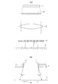
- an exposure apparatus used in the prior art includes a light source 1 that emits ultraviolet rays and a condenser lens 2 that irradiates a mask M with ultraviolet exposure light emitted from the light sources 1 as parallel light. And a fly-eye lens (lens array in which a plurality of unit lenses are arranged in a matrix) 3 disposed between the light source 1 and the condenser lens 2 and uniformizing the intensity distribution of the light irradiated to the mask M.
- the fly eye lenses 3 are arranged in a direction intersecting the scanning direction S of the exposed surface Bs.
- a light ray L1 that obliquely passes through the opening Ma of the mask M is generated by the condensing action of the fly-eye lens, and this light ray L1 is the opening Ma of the mask M.
- the surface Bs is spread by the collimation half angle ⁇ and irradiated to the exposed surface Bs.
- the exposed surface Bs is irradiated not only with the area Me immediately below the opening pattern of the mask M but also with the exposure light that protrudes from the area Me.
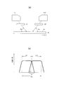
- a photo-alignment exposure apparatus as shown in FIG. 2 (a) is used.
- the first mask M1 having an opening pattern for exposing one divided area of the unit image area and the second mask M2 having an opening pattern for exposing the other divided area are provided.
- a first exposure apparatus Ex1 and a second exposure apparatus Ex2 are provided that are arranged apart from each other on the exposed surface Bs and expose the exposed surface Bs of the substrate B through the respective masks M1 and M2.
- the first exposure apparatus Ex1 irradiates the exposure light along the scanning direction S with ultraviolet exposure light having an irradiation angle ⁇ e (for example, 40 °) to the exposed surface Bs of the substrate B.
- the second exposure apparatus Ex2 is exposure light along the scanning direction S and irradiates the exposure surface Bs of the substrate B with ultraviolet exposure light having an irradiation angle of - ⁇ e (eg, -40 °).
- the exposure of the divided areas Da1 and Da2 in one unit image area Pa is sequentially performed with the exposure intensity shown in FIG. 2B, and the overexposure exposure by the collimation half angle shown in FIG.
- double exposure is performed in the range a near the boundary between the divided areas Da1 and Da2.
- the photo-alignment in the desired direction is Problems that cannot be obtained arise.
- the alignment disorder in the region a1 is caused by double exposure with insufficient intensity by the above-described collimation half angle, and its width becomes about 10 to 15 ⁇ m, but it becomes narrower due to high definition of the liquid crystal display panel. Under a situation where the width of the unit image area Pa is required, the width cannot be ignored in order to secure a sufficient effective image area.
- the present invention is an example of a problem to deal with such a problem. That is, when the photo-alignment exposure method is applied to the multi-domain method, the effective image area sufficient for eliminating the alignment disturbance near the boundary in the divided area obtained by dividing the unit image area and narrowing the unit image area It is an object of the present invention to ensure the above.
- the photo-alignment exposure apparatus and photo-alignment exposure method according to the present invention have at least the following characteristics.
- a photo-alignment exposure method and a photo-alignment exposure apparatus that divides each unit image area of a liquid crystal display element into a plurality of divided areas, and photo-aligns alignment material films in the divided areas in different directions, respectively.
- Condensing here means that light that spreads from the mask pattern and travels toward the non-exposure target area is collected within the exposure target.
- the same size projection and reduction projection are performed. , Including magnified projection.
- the light that is transmitted through the mask pattern and spreads by the collimation half angle is collected by the light collecting means, so that the spread can be suppressed and the exposed surface can be irradiated.
- the double-exposed region near the boundary of the divided region can be reduced, and the alignment disorder near the boundary in the divided region can be eliminated.
- the alignment disturbance near the boundary in the divided region obtained by dividing the unit image region can be eliminated. It is possible to secure a sufficient effective image area for narrowing the unit image area.
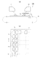
- FIG. 3A shows a configuration example of a photo-alignment exposure apparatus
- FIG. 3B shows a configuration example of a substrate (exposed surface).
- FIG. 3A shows a configuration example of a photo-alignment exposure apparatus
- FIG. 3B shows a configuration example of a substrate (exposed surface).
- FIG. 3A shows a configuration example of a photo-alignment exposure apparatus
- FIG. 3B shows a configuration example of a substrate (exposed surface).
- FIG. 3B shows a configuration example of a substrate (exposed surface).
- FIG. 3B shows a configuration example of a substrate (exposed surface).
- FIG. 3B shows a configuration example of a substrate (exposed surface).
- FIG. 3B shows a configuration example of a substrate (exposed surface).
- FIG. 3B shows a configuration example of a substrate (exposed surface).
- FIG. 3B shows a configuration example of a substrate (exposed surface).
- FIG. 3B shows a configuration example of
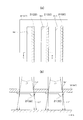
- FIG. 6A is a cross-sectional view in a direction intersecting the scanning direction S
- FIG. 6B is a cross-sectional view in the direction along the scanning direction S.
- 7A is a plan view
- FIG. 7B is a cross-sectional view taken along the line XX in FIG. 7A.
- FIG. 3 is an explanatory view showing a photo-alignment exposure method and a photo-alignment exposure apparatus according to an embodiment of the present invention.
- FIG. 3A shows a configuration example of a photo-alignment exposure apparatus
- FIG. 3B shows a configuration example of a substrate (exposed surface).
- the photo-alignment exposure apparatus 100 divides each unit image area Pa of the liquid crystal display element into a plurality of divided areas Da1 and Da2, and the alignment material films in the divided areas Da1 and Da2, respectively. It is an apparatus for photo-orienting in different directions.
- the alignment material film here is a photosensitive polymer film that exhibits a reversible photoisomerization reaction, and reacts with light (such as ultraviolet rays) obliquely applied to the surface of the alignment material film to produce a desired film. An orientation in the direction along the pretilt angle and the irradiation direction can be obtained.
- the unit image area Pa here refers to a pixel or a sub-pixel in which one pixel is divided for each of a plurality of colors (R, G, B), or a collection area thereof.
- the photo-alignment exposure apparatus 100 includes a first exposure apparatus 11, a mask M, and a second exposure apparatus 12, as shown in FIG.
- the first exposure apparatus 11 is an apparatus for executing a first exposure step of irradiating light at a light irradiation angle ⁇ 1 inclined with respect to the exposed surface of the entire unit image area Pa.
- the mask M and the second exposure apparatus 12 are for executing a second exposure step of exposing the second divided area Da2 adjacent to the first divided area Da1 described above, which is one of the divided areas described above.
- light is irradiated at a light irradiation angle ⁇ 2 inclined at an angle different from the light irradiation angle ⁇ 1 in the first exposure step.
- the first exposure apparatus 11 irradiates, for example, a light source for irradiating ultraviolet rays and light emitted from the light source onto the exposed surface Bs of the substrate B on which the alignment material film is formed at an inclination angle of angle ⁇ 1 (for example, 40 °). It has an optical system.
- the second exposure process is performed after the first exposure process, and the light is irradiated through the mask pattern of the mask M corresponding to the second divided area Da2, which is one of the divided areas, and the transmitted light of the mask pattern is emitted.
- the light is condensed by the light collecting means 13 and irradiated to the second divided region Da2.
- the entire surface of the unit image area Pa is photo-oriented in the first direction in the first exposure process by the first exposure apparatus 11, and then the second exposure apparatus 12 is performed thereafter.
- the second divided region Da2 is photo-aligned in the second direction.
- the alignment material film exhibits a reversible photoisomerization reaction, in the second exposure step in which exposure is performed later, only the overexposed portion is photoaligned in the second direction. The photo-alignment in the first direction is maintained in the portion not exposed in the exposure process.
- the light transmitted through the mask pattern of the mask M is condensed by the condensing means 13 to expose the second divided region Da2, so that the outer side of the second divided region Da2 by the collimation half angle ⁇ described above. Can be condensed inside the second divided region Da2. Therefore, in the second exposure step, light with insufficient intensity does not protrude into the first divided area Da1, and only the second divided area Da2 can be exposed with an intensity appropriate for the photo-alignment process. As a result, the overexposure exposure to other divided regions is suppressed, and the alignment disorder that occurs near the boundaries of the divided regions can be eliminated.
- the photo-alignment exposure apparatus 100 includes a substrate scanning unit 10, and the substrate B having the unit image area Pa on the exposed surface Bs is moved along the scanning direction S by the substrate scanning unit 10.
- the scanning direction S is an arrangement direction of the plurality of unit image areas Pa and a direction along the dividing line DL.
- the first exposure device 11 and the second exposure device 12 are arranged along the scanning direction S with a space therebetween, the first exposure process is performed on the upstream side in the scanning direction S, and the first exposure step is performed on the downstream side in the scanning direction S. Two exposure processes are performed.
- the light irradiated by the first exposure apparatus 11 and the second exposure apparatus 12 is a direction along the scanning direction S and is irradiated at different angles ( ⁇ 1, ⁇ 2) with respect to the exposed surface Bs. .
- the alignment material film exhibits a reversible photoisomerization reaction.
- the second material described above is used. An exposure process (exposure to one of the divided areas by the second exposure apparatus 12 and the mask M) is performed in advance, and then a first exposure process (exposure to the entire unit image area by the first exposure apparatus 11) is performed. Can do.
- FIG. 4 is an explanatory view showing a photo-alignment exposure method and a photo-alignment exposure apparatus according to another embodiment of the present invention.
- the photo-alignment exposure apparatus 200 includes the first exposure apparatus 11 and the first mask M1, the second exposure apparatus 12 and the second mask M2, and the first exposure apparatus 11 and the first mask M2.
- Condensing means 21 is provided between the mask M1 and the exposed surface Bs
- condensing means 22 is provided between the second mask M2 and the exposed surface Bs.
- the first exposure apparatus 11 irradiates light (for example, ultraviolet rays) at a light irradiation angle ⁇ 1 inclined with respect to one area (first divided area Da1) of the divided areas.
- a second exposure step of irradiating light (for example, ultraviolet rays) at ⁇ 1) is performed.
- light is irradiated through the first mask M1 and the second mask M2 each having a mask pattern corresponding to each divided region.
- the transmitted light of each mask pattern is condensed by the condensing means 21 and 22 and irradiated to the respective divided regions (first divided region Da1 and second divided region Da2). To do.
- the photo-alignment exposure apparatus 300 includes the first exposure apparatus 11 and the first mask M0, the second exposure apparatus 12 and the second mask M2, and the second exposure apparatus 12 and the second mask M2.
- Condensing means 22 is provided between the mask M2 and the exposed surface Bs.
- the first mask M0 is used for the proximity exposure of the first divided area Da1 which is one of the divided areas.
- the first exposure apparatus 11 irradiates light (for example, ultraviolet rays) at a light irradiation angle ⁇ 1 inclined with respect to one area (first divided area Da1) of the divided areas.
- a second exposure step of irradiating light (for example, ultraviolet rays) at ⁇ 1) is performed.
- light is irradiated through the first mask M0 or the second mask M2 each having a mask pattern corresponding to each divided region.
- the transmitted light of the mask pattern is condensed by the condensing means 22 and irradiated to the second divided region Da2.
- the substrate B having the unit image area Pa on the exposed surface Bs moves along the scanning direction S.
- the first exposure apparatus 11 and the second exposure apparatus 12 are arranged along the scanning direction S with a space therebetween, and the first exposure process is performed on the upstream side in the scanning direction S.
- the second exposure process is performed on the downstream side in the scanning direction S.
- the light irradiated by the first exposure apparatus 11 and the second exposure apparatus 12 is a direction along the scanning direction S and is irradiated at different angles ( ⁇ 1, ⁇ 2) with respect to the exposed surface Bs. .
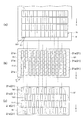
- FIG. 5 is an explanatory view showing a form example of a mask and condensing means used in the photo-alignment exposure method and photo-alignment exposure apparatus according to the embodiment of the present invention.
- the example of the 1st mask M1 and the condensing means 21 is shown in the figure, the 2nd mask M2 and the condensing means 22 can also be formed similarly.
- the first mask M1 has a mask pattern corresponding to the first divided region Da1
- the second mask M2 has a mask pattern corresponding to the second divided region Da2.
- 5A shows an example of the substrate B
- FIG. 5B shows an example of the first mask M1 and the condensing means
- FIG. 5C shows the first mask M1 and the condensing means. 21 shows another example of the form.
- the first mask M1 corresponding to the unit image area Pa includes a plurality of units as shown in FIG. A slit-like mask pattern (opening pattern) is formed.
- each opening Ma1 is disposed on the first divided area Da1 on the exposed surface Bs, and has an opening width W1 substantially equal to the first divided area Da1.
- the plurality of openings Ma1 are parallel to each other and are arranged in parallel in a direction intersecting the scanning direction S.
- the light condensing means 21 can be configured as a microlens array in which a plurality of single lenses 21a are arranged on the light transmission side of the opening Ma1, for example.
- the condensing means 21 is not limited to this example, and may be a lens in which cylindrical lenses (kamaboko convex lenses) are individually arranged in the opening Ma1, or a lenticular lens in which a plurality of kamaboko convex lenses are integrated.
- the example shown in FIG. 5C is an example in which the openings Ma1 for forming the mask pattern of the first mask M1 are arranged in a staggered manner.
- Each opening Ma1 is arranged on the first divided region Da1 as in the example shown in FIG.
- the lens diameter of the single lens 21a arranged corresponding to each opening Ma1 can be made relatively large.
- the lens diameter of the single lens 21a arranged corresponding to one opening Ma1 can be appropriately adjusted.
- FIG. 6 is an explanatory view showing the function of the light collecting means used in the photo-alignment exposure method and photo-alignment exposure apparatus according to the embodiment of the present invention.
- 6A is a cross-sectional view in a direction intersecting the scanning direction S
- FIG. 6B is a cross-sectional view in the direction along the scanning direction S.
- the condensing means 21 (22) condenses the light that passes through the mask pattern of the first mask M1 (second mask M2) on the first divided area Da1 (second divided area Da2).
- the light condensing means 21 (22) has a condensing action on the light L1 that is to be transmitted obliquely through the opening Ma1 of the first mask M1 (second mask M2), and there is no light condensing means 21 (22).
- the light L1 ′ protruding from the first divided area Da1 (second divided area Da2) can be collected in the first divided area Da1 (second divided area Da2).
- the condensing means 21 (22) the light passing through the opening Ma1 is condensed along the scanning direction S, but the exposed surface Bs moves along the scanning direction S. Therefore, uneven exposure due to this light collection does not occur.
- FIG. 7 is an explanatory view showing another example of the condensing means used in the photo-alignment exposure method and photo-alignment exposure apparatus according to the embodiment of the present invention.
- 7A is a plan view
- FIG. 7B is a cross-sectional view taken along the line XX in FIG. 7A.
- the condensing means 21 (22) is provided in the vicinity of the edge on the dividing line DL side in the opening Ma1 of the first mask M1 (second mask M2).
- a plurality of minute single lenses are arranged along the edge of the opening Ma1.
- the condensing action is exerted on the light L1 that is obliquely transmitted through the opening Ma1 of the first mask M1 (second mask M2) and exceeds the dividing line DL by the condensing means 21 (22).
- the light L1 ′ protruding from the first divided area Da1 (second divided area Da2) can be collected in the first divided area Da1 (second divided area Da2). .
- the light that passes through the mask pattern and spreads by the collimation half angle is collected by the light collecting means 13, 21, and 22, and the spread is suppressed to irradiate the exposed surface Bs. be able to.
- the double exposure area near the boundary between the divided areas Da1 and Da2 can be reduced, and the alignment disorder near the boundary in the divided areas Da1 and Da2 can be eliminated.
- alignment disorder is suppressed in all areas in the unit image area Pa, and the unit image area Pa is photo-oriented in one direction. Since it can be a region that is photo-aligned in a different direction from the region, when the photo-alignment exposure method is applied to the multi-domain method, an effective image region sufficient for narrowing the unit image region Pa should be secured. Can do.
Landscapes
- Physics & Mathematics (AREA)
- Nonlinear Science (AREA)
- Chemical & Material Sciences (AREA)
- Mathematical Physics (AREA)
- Crystallography & Structural Chemistry (AREA)
- General Physics & Mathematics (AREA)
- Optics & Photonics (AREA)
- Spectroscopy & Molecular Physics (AREA)
- Inorganic Chemistry (AREA)
- Liquid Crystal (AREA)
- Exposure And Positioning Against Photoresist Photosensitive Materials (AREA)
Description
11:第1露光装置,
12:第2露光装置,
13,21,22:集光手段,21a:単レンズ,
M,M0,M1,M2:マスク,Ma1:開口,
S:走査方向,B:基板,Bs:被露光面,Pa:単位画像領域,
DL:分割線,Da1,Da2:分割領域
Claims (7)
- 液晶表示素子の各単位画像領域を複数の分割領域に分割し、各分割領域の配向材料膜をそれぞれ異なる方向に光配向する光配向露光方法であって、
前記単位画像領域全面の被露光面に対して傾斜した光照射角度で光を照射する第1露光工程と、前記分割領域の一つの領域に対して、前記第1露光工程における光照射角度とは異なる角度で傾斜した光照射角度で光を照射する第2露光工程を有し、
前記第2露光工程は、前記分割領域の一つの領域に対応したマスクパターンを介して光を照射し、前記マスクパターンの透過光を集光手段によって集光して前記領域に照射することを特徴とする光配向露光方法。 - 液晶表示素子の各単位画像領域を複数の分割領域に分割し、各分割領域の配向材料膜をそれぞれ異なる方向に光配向する光配向露光方法であって、
前記分割領域の一つの領域の被露光面に対して傾斜した光照射角度で光を照射する第1露光工程と、前記分割領域の他の領域の被露光面に対して、前記第1露光工程における光照射角度とは異なる角度で傾斜した光照射角度で光を照射する第2露光工程を有し、
前記第1及び第2露光工程は、露光するそれぞれの分割領域に対応したマスクパターンを介して光を照射し、各マスクパターンの透過光を集光手段によって集光してそれぞれの分割領域に照射することを特徴とする光配向露光方法。 - 複数の前記単位画像領域の配列方向であり且つ前記分割領域の分割線に沿った走査方向に向けて前記単位画像領域を有する基板を移動させ、
前記走査方向の上流側で前記第1露光工程を行い、前記走査方向の下流側で前記第2露光工程を行い、
前記第1及び第2露光工程では、前記走査方向に沿った方向に光を照射することを特徴とする請求項1又は2記載の光配向露光方法。 - 液晶表示素子の各単位画像領域を複数の分割領域に分割し、各分割領域の配向材料膜をそれぞれ異なる方向に光配向する光配向露光方法であって、
前記分割領域の一つの領域に対して傾斜した光照射角度で光を照射する露光工程を有し、
前記露光工程は、露光する分割領域に対応したマスクパターンを介して光を照射し、前記マスクパターンの透過光を集光手段によって集光して、露光する分割領域に照射することを特徴とする光配向露光方法。 - 液晶表示素子の各単位画像領域を複数の分割領域に分割し、各分割領域の配向材料膜をそれぞれ異なる方向に光配向する光配向露光装置であって、
前記分割領域の一つの領域に対応したマスクパターンを有するマスクと、
前記分割領域の一つの領域の被露光面に対して、前記マスクを介して傾斜した光照射角度で光を照射する露光装置と、
前記マスクパターンの透過光を集光して、露光する分割領域に照射する集光手段とを備えることを特徴とする光配向露光装置。 - 複数の前記単位画像領域の配列方向であり且つ前記分割領域の分割線に沿って前記単位画像領域を有する基板を走査する基板走査手段を備え、
前記基板走査手段の走査方向に沿って間隔を空けて複数の前記露光装置を配置し、
複数の前記露光装置は、前記走査方向に沿った方向で且つ被露光面に対して異なる角度で光を照射することを特徴とする請求項5記載の光配向露光装置。 - 前記集光手段は、前記マスクパターンに沿って複数の単レンズを配置したマイクロレンズアレイであることを特徴とする請求項5又は6記載の光配向露光装置。
Priority Applications (3)
| Application Number | Priority Date | Filing Date | Title |
|---|---|---|---|
| CN201380034672.8A CN104412152B (zh) | 2012-07-05 | 2013-03-29 | 光取向曝光方法及光取向曝光装置 |
| KR1020157000071A KR20150035992A (ko) | 2012-07-05 | 2013-03-29 | 광배향 노광방법 및 광배향 노광장치 |
| US14/412,898 US9244311B2 (en) | 2012-07-05 | 2013-03-29 | Photo-alignment exposure method and photo-alignment exposure device |
Applications Claiming Priority (2)
| Application Number | Priority Date | Filing Date | Title |
|---|---|---|---|
| JP2012-151629 | 2012-07-05 | ||
| JP2012151629A JP6078843B2 (ja) | 2012-07-05 | 2012-07-05 | 光配向露光方法及び光配向露光装置 |
Publications (1)
| Publication Number | Publication Date |
|---|---|
| WO2014006943A1 true WO2014006943A1 (ja) | 2014-01-09 |
Family
ID=49881708
Family Applications (1)
| Application Number | Title | Priority Date | Filing Date |
|---|---|---|---|
| PCT/JP2013/059576 Ceased WO2014006943A1 (ja) | 2012-07-05 | 2013-03-29 | 光配向露光方法及び光配向露光装置 |
Country Status (6)
| Country | Link |
|---|---|
| US (1) | US9244311B2 (ja) |
| JP (1) | JP6078843B2 (ja) |
| KR (1) | KR20150035992A (ja) |
| CN (1) | CN104412152B (ja) |
| TW (1) | TWI576641B (ja) |
| WO (1) | WO2014006943A1 (ja) |
Families Citing this family (7)
| Publication number | Priority date | Publication date | Assignee | Title |
|---|---|---|---|---|
| CN106133566B (zh) * | 2014-04-03 | 2020-04-10 | 罗利克有限公司 | 结合视差光学器件的具有构图的各向异性的光学设备 |
| CN104062818B (zh) * | 2014-06-27 | 2017-10-24 | 上海天马微电子有限公司 | 一种液晶显示装置及其制造方法 |
| WO2017027444A1 (en) * | 2015-08-07 | 2017-02-16 | Kent State University | Photopatterning of molecular orientations |
| CN107966881B (zh) * | 2017-03-15 | 2018-11-23 | 上海微电子装备(集团)股份有限公司 | 光刻装置及方法 |
| JP2019046910A (ja) * | 2017-08-31 | 2019-03-22 | 株式会社ブイ・テクノロジー | レーザアニール装置及びレーザアニール方法 |
| JP2019121743A (ja) * | 2018-01-10 | 2019-07-22 | 株式会社ブイ・テクノロジー | レーザ照射装置、及び、レーザ照射方法 |
| CN112904620A (zh) * | 2021-01-27 | 2021-06-04 | 福州大学 | 双畴光配向lcd光路系统 |
Citations (4)
| Publication number | Priority date | Publication date | Assignee | Title |
|---|---|---|---|---|
| JP2007219191A (ja) * | 2006-02-17 | 2007-08-30 | V Technology Co Ltd | 液晶表示用基板の製造方法 |
| JP2008020706A (ja) * | 2006-07-13 | 2008-01-31 | Seiko Epson Corp | マスク及び液晶表示装置の製造方法 |
| WO2010140505A1 (ja) * | 2009-06-03 | 2010-12-09 | 株式会社ブイ・テクノロジー | レーザアニール方法及びレーザアニール装置 |
| JP2012063652A (ja) * | 2010-09-17 | 2012-03-29 | V Technology Co Ltd | 露光装置 |
Family Cites Families (1)
| Publication number | Priority date | Publication date | Assignee | Title |
|---|---|---|---|---|
| US20030072896A1 (en) * | 2001-06-07 | 2003-04-17 | The Hong Kong University Of Science And Technology | Photo-induced alignment materials and method for LCD fabrication |
-
2012
- 2012-07-05 JP JP2012151629A patent/JP6078843B2/ja active Active
-
2013
- 2013-03-29 KR KR1020157000071A patent/KR20150035992A/ko not_active Withdrawn
- 2013-03-29 WO PCT/JP2013/059576 patent/WO2014006943A1/ja not_active Ceased
- 2013-03-29 US US14/412,898 patent/US9244311B2/en not_active Expired - Fee Related
- 2013-03-29 CN CN201380034672.8A patent/CN104412152B/zh not_active Expired - Fee Related
- 2013-04-30 TW TW102115527A patent/TWI576641B/zh not_active IP Right Cessation
Patent Citations (4)
| Publication number | Priority date | Publication date | Assignee | Title |
|---|---|---|---|---|
| JP2007219191A (ja) * | 2006-02-17 | 2007-08-30 | V Technology Co Ltd | 液晶表示用基板の製造方法 |
| JP2008020706A (ja) * | 2006-07-13 | 2008-01-31 | Seiko Epson Corp | マスク及び液晶表示装置の製造方法 |
| WO2010140505A1 (ja) * | 2009-06-03 | 2010-12-09 | 株式会社ブイ・テクノロジー | レーザアニール方法及びレーザアニール装置 |
| JP2012063652A (ja) * | 2010-09-17 | 2012-03-29 | V Technology Co Ltd | 露光装置 |
Also Published As
| Publication number | Publication date |
|---|---|
| TWI576641B (zh) | 2017-04-01 |
| US9244311B2 (en) | 2016-01-26 |
| CN104412152A (zh) | 2015-03-11 |
| JP6078843B2 (ja) | 2017-02-15 |
| US20150192830A1 (en) | 2015-07-09 |
| JP2014016379A (ja) | 2014-01-30 |
| TW201403188A (zh) | 2014-01-16 |
| KR20150035992A (ko) | 2015-04-07 |
| CN104412152B (zh) | 2018-04-13 |
Similar Documents
| Publication | Publication Date | Title |
|---|---|---|
| JP6078843B2 (ja) | 光配向露光方法及び光配向露光装置 | |
| JP5341941B2 (ja) | 配向処理方法および配向処理装置 | |
| KR102272435B1 (ko) | 편광광 조사장치 | |
| WO2011132620A1 (ja) | 配向処理方法及び配向処理装置 | |
| TWI770239B (zh) | 曝光裝置及曝光方法 | |
| KR101945068B1 (ko) | 패턴 위상차 필름의 제조 방법, 패턴 위상차 필름 및 화상 표시 장치 | |
| JP5564695B2 (ja) | 光配向露光装置及び光配向露光方法 | |
| JP5953512B2 (ja) | 光配向露光装置及び光配向露光方法 | |
| JP2008164729A (ja) | 光照射器及び光照射装置並びに露光方法 | |
| CN110945627A (zh) | 激光退火装置及激光退火方法 | |
| JP2019028084A (ja) | 露光装置 | |
| KR101347552B1 (ko) | 마스크 및 이를 포함하는 광학필터 제조장치 | |
| JP5581017B2 (ja) | 露光方法、並びに露光装置 | |
| JP2014038178A (ja) | 光配向露光装置 | |
| JP2014052615A (ja) | 光配向露光用マスク、光配向露光装置 | |
| JP2015049486A (ja) | パターン位相差フィルムの製造方法、露光装置及びマスク | |
| JP2015049418A (ja) | パターン位相差フィルムの製造方法、露光装置及びマスク | |
| JP2014194481A (ja) | 光配向露光装置 |
Legal Events
| Date | Code | Title | Description |
|---|---|---|---|
| 121 | Ep: the epo has been informed by wipo that ep was designated in this application |
Ref document number: 13812950 Country of ref document: EP Kind code of ref document: A1 |
|
| ENP | Entry into the national phase |
Ref document number: 20157000071 Country of ref document: KR Kind code of ref document: A |
|
| NENP | Non-entry into the national phase |
Ref country code: DE |
|
| WWE | Wipo information: entry into national phase |
Ref document number: 14412898 Country of ref document: US |
|
| 122 | Ep: pct application non-entry in european phase |
Ref document number: 13812950 Country of ref document: EP Kind code of ref document: A1 |