WO2014003174A1 - Antenne en f inversé - Google Patents
Antenne en f inversé Download PDFInfo
- Publication number
- WO2014003174A1 WO2014003174A1 PCT/JP2013/067844 JP2013067844W WO2014003174A1 WO 2014003174 A1 WO2014003174 A1 WO 2014003174A1 JP 2013067844 W JP2013067844 W JP 2013067844W WO 2014003174 A1 WO2014003174 A1 WO 2014003174A1
- Authority
- WO
- WIPO (PCT)
- Prior art keywords
- antenna
- inverted
- plane
- radiating element
- type antenna
- Prior art date
Links
Images


Classifications
-
- H—ELECTRICITY
- H01—ELECTRIC ELEMENTS
- H01Q—ANTENNAS, i.e. RADIO AERIALS
- H01Q21/00—Antenna arrays or systems
- H01Q21/24—Combinations of antenna units polarised in different directions for transmitting or receiving circularly and elliptically polarised waves or waves linearly polarised in any direction
-
- H—ELECTRICITY
- H01—ELECTRIC ELEMENTS
- H01Q—ANTENNAS, i.e. RADIO AERIALS
- H01Q1/00—Details of, or arrangements associated with, antennas
- H01Q1/12—Supports; Mounting means
- H01Q1/22—Supports; Mounting means by structural association with other equipment or articles
- H01Q1/24—Supports; Mounting means by structural association with other equipment or articles with receiving set
- H01Q1/241—Supports; Mounting means by structural association with other equipment or articles with receiving set used in mobile communications, e.g. GSM
- H01Q1/242—Supports; Mounting means by structural association with other equipment or articles with receiving set used in mobile communications, e.g. GSM specially adapted for hand-held use
- H01Q1/243—Supports; Mounting means by structural association with other equipment or articles with receiving set used in mobile communications, e.g. GSM specially adapted for hand-held use with built-in antennas
-
- H—ELECTRICITY
- H01—ELECTRIC ELEMENTS
- H01Q—ANTENNAS, i.e. RADIO AERIALS
- H01Q5/00—Arrangements for simultaneous operation of antennas on two or more different wavebands, e.g. dual-band or multi-band arrangements
- H01Q5/30—Arrangements for providing operation on different wavebands
- H01Q5/307—Individual or coupled radiating elements, each element being fed in an unspecified way
- H01Q5/342—Individual or coupled radiating elements, each element being fed in an unspecified way for different propagation modes
- H01Q5/357—Individual or coupled radiating elements, each element being fed in an unspecified way for different propagation modes using a single feed point
- H01Q5/364—Creating multiple current paths
- H01Q5/371—Branching current paths
-
- H—ELECTRICITY
- H01—ELECTRIC ELEMENTS
- H01Q—ANTENNAS, i.e. RADIO AERIALS
- H01Q5/00—Arrangements for simultaneous operation of antennas on two or more different wavebands, e.g. dual-band or multi-band arrangements
- H01Q5/30—Arrangements for providing operation on different wavebands
- H01Q5/378—Combination of fed elements with parasitic elements
- H01Q5/385—Two or more parasitic elements
-
- H—ELECTRICITY
- H01—ELECTRIC ELEMENTS
- H01Q—ANTENNAS, i.e. RADIO AERIALS
- H01Q9/00—Electrically-short antennas having dimensions not more than twice the operating wavelength and consisting of conductive active radiating elements
- H01Q9/04—Resonant antennas
- H01Q9/16—Resonant antennas with feed intermediate between the extremities of the antenna, e.g. centre-fed dipole
- H01Q9/26—Resonant antennas with feed intermediate between the extremities of the antenna, e.g. centre-fed dipole with folded element or elements, the folded parts being spaced apart a small fraction of operating wavelength
-
- H—ELECTRICITY
- H01—ELECTRIC ELEMENTS
- H01Q—ANTENNAS, i.e. RADIO AERIALS
- H01Q9/00—Electrically-short antennas having dimensions not more than twice the operating wavelength and consisting of conductive active radiating elements
- H01Q9/04—Resonant antennas
- H01Q9/30—Resonant antennas with feed to end of elongated active element, e.g. unipole
- H01Q9/42—Resonant antennas with feed to end of elongated active element, e.g. unipole with folded element, the folded parts being spaced apart a small fraction of the operating wavelength
Definitions
- the present invention relates to an inverted-F antenna, and more particularly to an inverted-F antenna suitable for mounting on an integrated antenna device.
- antennas that operate in various frequency bands are required.
- terrestrial digital broadcasting such as FM / AM broadcasting, DAB (Digital Audio Broadcast), 3G (3rd generation mobile phone), LTE (Long Term Evolution), GPS (Global Positioning System):
- VICS registered trademark
- ETC Electronic Toll Collection
- antennas that operate in different frequency bands are often realized as separate antenna devices.
- an FM / AM broadcast antenna is realized as a whip antenna placed on a roof top
- a digital terrestrial broadcast antenna is realized as a film antenna attached to a windshield.
- the integrated antenna device refers to an antenna device including a plurality of antennas that operate in different frequency bands.
- Examples of such an integrated antenna device include those described in Patent Documents 1 to 5.
- the integrated antenna device described in Patent Document 1 includes GPS and ETC antennas.
- the integrated antenna device described in Patent Document 2 includes antennas for 3G and GPS.
- the integrated antenna device described in Patent Document 3 includes antennas for ETC, GPS, VICS (registered trademark), telephone main, and telephone sub.
- the integrated antenna device described in Patent Document 4 includes antennas for GPS, ETC, first phone, and second phone.
- the integrated antenna device described in Patent Document 5 includes an antenna that operates in a band of 100 kHz to 1 GHz (FM / AM broadcasting, terrestrial digital broadcasting such as DAB, VICS, etc.) and a band of 1 GHz or more (GPS, satellite DAB, etc.) It is equipped with the antenna which operate
- JP 2007-158957 (released June 21, 2007) Japanese Published Patent Publication “JP 2009-17116” (released January 22, 2009) Japanese Patent Publication “JP 2009-267765 A” (published on November 12, 2009) Japanese Published Patent Publication “JP 2010-81500” (published April 8, 2010) US Pat. No. 6,396,447 (registered on May 28, 2002)
- An inverted F-type antenna is promising as a telephone antenna such as a 3G / LTE antenna mounted on such an integrated antenna.
- a planar inverted F-type antenna in which a ground plane, a radiating element, and a short-circuit portion are formed in the same plane can be realized as a pattern on a substrate and is suitable for mounting on an integrated antenna.
- the conventional planar inverted F-type antenna has a problem that a large space is required to arrange the ground plane, the radiating element, and the short-circuit portion.
- the electromagnetic field formed by the induced current flowing through the ground plane cancels the electromagnetic field formed by the current flowing through the radiating element, there is a problem that it is difficult to obtain a high gain.
- the present invention has been made in view of the above problems, and its object is to solve the above-mentioned problems of conventional planar inverted-F antennas and to realize an inverted-F antenna that can be easily mounted on an integrated antenna. There is to do.
- an inverted F-type antenna includes at least a ground plane disposed on a first plane and a second plane that intersects (for example, is orthogonal to) the first plane.
- a radiating element partially disposed; and a short-circuit portion that short-circuits the ground plane and the radiating element, wherein the radiating element is a grounding portion extending from a root portion of the short-circuiting portion, and is grounded with a tip grounded And an arm portion extending in a direction intersecting (for example, orthogonal to) the ground plane from a root portion of the short-circuit portion, and having an open end.
- an inverted F-type antenna that can be arranged in a narrower space than a planar inverted F-type antenna and that can obtain a higher gain than a planar inverted F-type antenna.
- FIG. 3 is a development view showing a first specific example of the inverted F-type antenna shown in FIG. 1. It is a graph which shows the VSWR characteristic of the inverted F type antenna shown in FIG.
- FIG. 6 is a development view showing a second specific example of the inverted F-type antenna shown in FIG. 1. It is a graph which shows the VSWR characteristic of the inverted F type antenna shown in FIG.
- FIG. 6 is a development view showing a third specific example of the inverted F-type antenna shown in FIG. 1. It is a graph which shows the VSWR characteristic of the inverted F type antenna shown in FIG. FIG.
- FIG. 6 is a development view showing a fourth specific example of the inverted F-type antenna shown in FIG. 1. It is a graph which shows the VSWR characteristic of the inverted F type antenna shown in FIG. It is a graph which shows the radiation pattern in the low frequency side request
- FIG. 7 is a development view showing a fifth specific example of the inverted F-type antenna shown in FIG. 1.
- FIG. 7 is a development view illustrating a sixth specific example of the inverted F-type antenna illustrated in FIG. 1.
- A) is a top view which shows the structure of the loop antenna 2 which can be arrange
- B) is an equivalent circuit of a parasitic element group included in the loop antenna. It is a graph which shows the radiation pattern of the loop antenna shown in FIG.
- FIG. 20 is a three-view diagram illustrating a configuration of a base portion included in the integrated antenna device illustrated in FIG. 19. It is a perspective view which shows the additional structure which the integrated antenna apparatus shown in FIG. 19 may be equipped with.
- A is a perspective view of a radome
- (b) is a perspective view of a spacer
- (c) is a perspective view of a rubber base.
- An antenna including a ground plane that is a grounded planar conductor and a radiating element that is a non-grounded linear or strip-like conductor that is separated from the ground plane is referred to as a “monopole antenna”.
- the monopole antenna further including a short-circuit portion, and the ground plate and the radiating element are short-circuited by the short-circuit portion is referred to as an “inverted F antenna”.
- the antenna according to the present embodiment is similar to the inverted F antenna in that it includes a ground plane, a radiating element, and a short-circuit portion as will be described later. For this reason, the antenna according to this embodiment is hereinafter referred to as an “inverted F-type antenna”. However, the antenna according to the present embodiment is different from the inverted F antenna in that the radiating element is grounded as described later. It is in view of this point that the antenna according to the present embodiment is described as an “inverted F“ type ”antenna” without being described as an “inverted F antenna”.
- FIG. 1 is a perspective view showing a basic configuration of an inverted F-type antenna 1.
- the inverted F-type antenna 1 is a two-dimensional antenna that can be deployed on a single plane, but is designed on the assumption that it is used in a folded state as shown in FIG.
- the inverted F-type antenna 1 includes a ground plane 11, a radiating element 12, and a short-circuit portion 13.
- the ground plane 11, the radiating element 12, and the short-circuit portion 13 are integrally formed of one conductor foil (for example, copper foil), and are mounted on a printed board together with the other loop antenna 2, for example.
- the three-dimensional structure of the inverted F-type antenna 1 shown in FIG. 1 is realized by bending the printed circuit board on which the inverted F-type antenna 1 is mounted.
- the inverted F-type antenna 1 is a dual frequency antenna that operates in at least two frequency bands. Specifically, it is a 3G / LTE antenna that operates in one of the 3G frequency bands and one of the LTE frequency bands. More specifically, 3G that operates in a frequency band of 761 MHz to 960 MHz (hereinafter referred to as “low frequency side required band”) and a frequency band of 1710 MHz to 2130 MHz (hereinafter referred to as “high frequency side required band”). / LTE antenna.
- the ground plane 11 is composed of a planar conductor.
- a rectangular conductor foil is disposed on the first plane S ⁇ b> 1 (a plane parallel to the zx plane in FIG. 1), and this is used as the ground plane 11.
- the orientation of the ground plane 11 is determined so that the longitudinal direction thereof is parallel to the x axis.
- the posture of the inverted F-type antenna 1 is reduced (the size in the z-axis direction is reduced).
- a notable point in the base plate 11 is that two notches 11a to 11b extending in the z-axis negative direction from the longer side on the z-axis positive direction side are formed, and the z-axis is formed between these two notches 11a to 11b.
- the feed point P is provided at the tip of the rectangular portion 11c extending in the positive direction.
- the longitudinal direction of the rectangular portion 11c of the ground plane 11 is the main portion of the radiating element 12. It will be orthogonal to the longitudinal direction of the portion 12a.
- the direction of the current flowing through the ground plane 11 in the vicinity of the feeding point P is restricted to the z-axis direction.
- the electromagnetic field generated by the current flowing through the radiating element 12 is generated by the current flowing through the ground plane 11. It is possible to suppress a decrease in gain due to cancellation by the field.
- the radiating element 12 is constituted by a linear or strip conductor.
- the strip-shaped conductor foil is disposed on a second plane S2 (a plane parallel to the xy plane in FIG. 1) orthogonal to the first plane S1, and this is disposed on the main portion 12a of the radiating element 12.
- the main direction of the radiating element 12 is set so that its longitudinal direction is parallel to the x-axis. The direction of the portion 12a is determined.
- a configuration in which a part of the radiating element 12 is arranged on the first plane S1 together with the ground plane 11 by bending the radiating element 12 and a feeding point Q is provided in the part is adopted.
- the radiating element 12 includes an arm portion 12b and a grounding portion 12c described below.
- the main portion 12a, the arm portion 12b, and the grounding portion 12c are integrally formed from one conductor foil, but the present invention is not limited to this. That is, the radiation element 12 may be realized by connecting the main part 12a, the arm part 12b, and the grounding part 12c that are individually formed.
- the arm portion 12b is a linear or strip-like conductor extending from the main portion 12a, and has an open end opposite to the main portion 12a side.
- the strip-shaped conductor that linearly extends in the y-axis positive direction from the end on the x-axis negative direction side of the main portion 12a is orthogonal to both the first plane S1 and the second plane S2.
- the plane S3 a plane parallel to the yz plane in FIG. 1 and used as the arm portion 12b.
- the inverted F-type antenna 1 by providing such an arm portion 12b, a resonance point is provided in the low frequency side required band.
- the first point to be noted regarding the arm portion 12b is that the arm portion 12b extends linearly in a direction orthogonal to the first plane S1 on which the ground plane 11 is disposed. Thereby, the resonance frequency band produced by the arm part 12b becomes wide.
- the second point to be noted regarding the arm portion 12b is that it is arranged not on the second plane S2 but on the third plane S3. Thereby, it is not necessary to reduce the space for arranging another loop antenna 2 on the second plane S2 in order to avoid interference with the arm portion 12b.
- the grounding part 12c is a linear or strip-like conductor extending from the main part 12a, and has an end opposite to the main part 12a side grounded (connected to the ground).
- a strip-like conductor extending in the negative z-axis direction from the end on the negative x-axis side of the main portion 12a (the root of the short-circuit portion 13 described later) is disposed on the third surface S3 and grounded. Used as part 12c.
- the short-circuit portion 13 is a portion for short-circuiting the ground plane 11 and the radiating element 12 in the inverted F-type antenna 1 and is constituted by a linear or strip-shaped conductor.
- the strip-shaped conductor foil that extends from the end portion of the main portion 12a on the negative x-axis side (the root of the grounding portion 12c described above) to the end portion of the ground plane 11 on the negative x-axis direction is the first.
- On the plane S ⁇ b> 1 On the plane S ⁇ b> 1, and this is used as the short-circuit portion 13.
- the inverted F-type antenna 1 by providing such a short-circuit portion 13, the potential of the end portion on the x-axis negative direction side of the main portion 12 a is controlled to 0V.
- the position of the feeding point Q in the radiating element 12 is determined according to a standard inverse F antenna design method. That is, the input impedance of the inverted F-type antenna 1 is coaxial under the assumption that the potential of the root of the short-circuit portion 13 (in this embodiment, the end of the main portion 12a on the x-axis negative direction side) is controlled to 0V. It is determined to match the output impedance of the cable. However, simply connecting the short-circuit portion 13 to the end portion of the main portion 12a on the x-axis direction side cannot sufficiently suppress the variation in reactance at the end portion. For this reason, impedance matching with a coaxial cable cannot be guaranteed.
- FIG. 2 is a development view showing a first specific example of the inverted F-type antenna 1.
- the three-dimensional shape shown in FIG. 1 is realized by bending the straight line L and the straight line M so as to have ridgelines.
- the features of the ground plane 11, the radiating element 12, and the short-circuit portion 13 constituting the inverted F-type antenna 1 are as already described with reference to FIG.
- a rectangular conductor foil having a long side of 35 mm and a short side of 11 mm formed with notches 11a to 11b having a width of 5 mm and a length of 9 mm is used as the ground plane 11.
- the interval between the two notches 11a to 11b is determined so that the width of the rectangular portion 11c is 4 mm.
- the length of the main portion 12a is 55 mm
- the length of the arm portion 12b is 63 mm.
- the inverted F-type antenna 1 is bent so that the straight line L is the ridgeline
- a configuration in which the inverted F-type antenna 1 is bent so that the straight line L ′ is the ridgeline may be employed.
- the main portion 12a of the radiating element 12 is disposed on both the first plane S1 (see FIG. 1) and the second plane S2 (see FIG. 1), whereas the latter is the latter.
- the main part 12a of the radiating element 12 is arranged only on the second plane S2.
- the inverted F-type antenna 1 is bent so that the straight line M is the ridgeline
- a configuration in which the inverted F-type antenna 1 is bent so that the straight line M ′ is the ridgeline may be employed.
- the arm portion 12b of the radiating element 12 is arranged on the third plane S3 (see FIG. 1), whereas when the latter configuration is adopted, the arm portion 12b of the radiating element 12 is arranged. Is arranged on the second plane S2.
- FIG. 3 is a graph showing the VSWR characteristics of the inverted F-type antenna 1 according to this example. From the graph shown in FIG. 3, a resonance point is formed in the low frequency side required band, and a region where VSWR is 4 or less is formed in both the low frequency side required band and the high frequency side required band. I can read that
- the reason why the resonance point is formed in the low frequency side required band is that the radiating element 12 is provided with the arm portion 12b.
- the region where the VSWR is 4 or less is formed in both the low-frequency side required band and the high-frequency side required band because the radiating element 12 is provided with the grounding portion 12c, thereby achieving impedance matching in the region. This is because the.
- FIG. 4 is a development view showing a second specific example of the inverted F-type antenna 1.
- the change from the inverted F-type antenna 1 according to the first specific example is that an arm portion 12d is added to the radiating element 12 as shown in FIG.
- the arm portion 12d is a linear or strip-like conductor extending from the main portion 12a, and has an open end opposite to the main portion 12a side.
- a strip-like conductor extending linearly in the y-axis positive direction from the end on the x-axis positive direction side of the main portion 12a is disposed on the second plane S2 (see FIG. 1), and this is disposed on the arm. Used as part 12d.
- FIG. 5 is a graph showing the VSWR characteristics of the inverted F-type antenna 1 according to this example. As shown in FIG. 5, by adding the arm portion 12d to the radiating element 12, a new resonance point is generated in the low frequency side required band. Thereby, the operation band in the low frequency side request band is expanded.
- FIG. 6 is a development view showing a third specific example of the inverted F-type antenna 1.
- the change from the inverted F-type antenna 1 according to the second specific example is that a part of the arm portion 12d is meandered as shown in FIG.
- a part of the arm portion 12d is bent into a U shape, and this is used as a meander portion 12d1.
- the meander part 12d1 is formed on the x-axis negative direction side of the arm part 12d so that it is not necessary to enlarge the space required for the arrangement of the arm part 12d.
- FIG. 7 is a graph showing the VSWR characteristics of the inverted F-type antenna 1 according to this example. As shown in FIG. 7, a new resonance point is generated in the high frequency side required band by making a part of the arm portion 12d meander. Thereby, the operation band in the high frequency request band is expanded.
- FIG. 8 is a development view showing a fourth specific example of the inverted F-type antenna 1.
- the change from the inverted F-type antenna 1 according to the third specific example is that a short-circuit portion 12e for short-circuiting the intermediate portion of the main portion 12a and the intermediate portion of the arm portion 12d is added.
- the short-circuit portion 12e in this specific example includes a first straight portion 12e1 extending in the y-axis positive direction from the intermediate portion of the main portion 12a, and an arm portion 12d extending from the tip of the first straight portion 12e1 in the x-axis positive direction. And a second straight line portion 12e2 that reaches the middle portion.
- a new current path that passes through these linear portions 12e1 to 12e2 is added to the current path from the feeding point Q to the tip of the arm portion 12d.
- the short-circuit portion 12e extends from the intermediate portion of the first straight portion 12e1 in the x-axis positive direction, and extends from the intermediate portion of the third straight portion 12e3 in the y-axis negative direction.
- a fourth straight part 12e4 reaching the part 12a As a result, a new current path that passes through these linear portions 12e3 to 12e4 is added to the current path from the feeding point Q to the tip of the arm portion 12d.
- FIG. 9 is a graph showing the VSWR characteristics of the inverted F-type antenna 1 according to this example. As shown in FIG. 9, by adding a short-circuit portion 12 e to the radiating element 12, a new resonance point is generated in the high frequency side required band. Thereby, the operation band in the high frequency request band is further expanded.
- FIG. 10 is a graph showing a radiation pattern of the inverted F antenna 1 according to this specific example in the low frequency side required band (specifically, 850 MHz).
- A shows the azimuth angle ( ⁇ ) dependence of the gain in the xy plane
- (b) shows the elevation angle ( ⁇ ) dependence of the gain in the zx plane
- (c) shows the gain in the yz plane.
- the elevation angle ( ⁇ ) dependence is shown.
- the inverted F-type antenna 1 according to this specific example can obtain a high gain in the upper half space regardless of the azimuth angle in the low frequency side required band.
- FIG. 11 is a graph showing a radiation pattern of the inverted F-type antenna 1 according to this example in the high frequency side required band (specifically, 1800 MHz).
- A shows the azimuth angle ( ⁇ ) dependence of the gain in the xy plane
- (b) shows the elevation angle ( ⁇ ) dependence of the gain in the zx plane
- (c) shows the gain in the yz plane.
- the elevation angle ( ⁇ ) dependence is shown.
- the inverted F-type antenna 1 according to this specific example can obtain a high gain in the upper half space regardless of the azimuth angle even in the high frequency side required band.
- the characteristics of the inverted F-type antenna 1 according to this specific example shown in FIGS. 10 to 11 are extremely advantageous in a 3G / LTE antenna mounted on a car whose direction changes every moment.
- inverted F-type antenna 1 can be modified to the form shown in FIG. 12, the form shown in FIG.
- the fifth specific example shown in FIG. 12 is similar to the first specific example shown in FIG. 4 in that the short-circuit portion 12f1 that short-circuits the intermediate portion of the main portion 12a and the intermediate portion of the arm portion 12d and the intermediate portion of the arm portion 12d. And a second branch 12f3 extending from the middle part of the main part 12a.
- the sixth specific example shown in FIG. 13 is similar to the first specific example shown in FIG. 4 in that the short-circuit portion 12f1 that short-circuits the intermediate portion of the main portion 12a and the intermediate portion of the arm portion 12d, and the intermediate portion of the main portion 12a. And a second branch 12f3 extending from.
- inverted F-type antenna 1 In the inverted F-type antenna 1 according to the fifth to sixth specific examples, as with the inverted F-type antenna 1 according to the first to fourth specific examples, good characteristics as a 3G / LTE antenna can be obtained.
- loop antenna A loop antenna 2 that can be arranged on the same plane as the inverted F-type antenna 1 according to the present embodiment will be described with reference to FIGS.
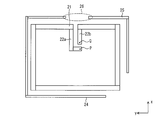
- FIG. 14A is a plan view showing the configuration of the loop antenna 2.
- FIG. 14B is a circuit diagram showing an equivalent circuit of the parasitic elements 24 to 25 included in the loop antenna 2.
- the loop antenna 2 includes a radiating element 21, a pair of feeding portions 22a to 22b, a pair of short-circuiting portions 23a to 23b, a first parasitic element 24, and a second parasitic element. And a power feeding element 25.
- the radiating element 21, the power feeding portions 22a to 22b, and the short-circuit portions 23a to 23b are integrally formed from a single conductor foil (for example, copper foil).
- the first parasitic element 24 is composed of another conductor foil that is isolated from the conductor foil constituting the radiating element 21 and the like.
- the second parasitic element 25 is composed of another conductive foil that is isolated from the conductive foil that forms the radiating element 21 and the conductive foil that forms the first parasitic element 24.
- the radiating element 21 is composed of a linear or strip conductor arranged on a closed curve.
- a strip-shaped conductor foil for example, a copper foil
- One end portion 21a of the radiating element 21 faces the other end portion 21b of the radiating element 21 through a straight line extending in the 0 o'clock direction from the center of the ellipse.
- the power feeding part 22a is a linear or strip-like conductor arranged on a line segment extending from one end 21a of the radiating element 21 to the vicinity of the center of the ellipse.
- a strip-shaped conductor foil having a width of 1 mm is used as the power feeding portion 22a.
- a feeding point P to which the outer conductor of the coaxial cable is connected is provided at the tip of the feeding part 22a. Therefore, one end portion 21a of the radiating element 21 is connected to the outer conductor of the coaxial cable via the power feeding portion 22a.
- the feeding part 22b is a linear or strip-like conductor arranged on a line segment from the other end 21b of the radiating element 21 to the vicinity of the center of the ellipse.
- a strip-shaped conductor foil having a width of 1 mm is used as the power feeding portion 22b.
- a feeding point Q to which the inner conductor of the coaxial cable is connected is provided at the tip of the feeding part 22b. Therefore, the other end portion 21b of the radiating element 21 is connected to the inner conductor of the coaxial cable via the feeding portion 22b.
- the short-circuit portion 23a is configured to short-circuit the point 21c on the radiating element 21 located in the 9 o'clock direction as viewed from the center of the ellipse and the feeding point P.
- a strip-shaped conductor foil having a width of 1 mm which is disposed on a line segment from the point 21c on the radiating element 21 to the vicinity of the center of the ellipse, is used as the short-circuit portion 23a.
- the short-circuit portion 23b is configured to short-circuit the point 21d on the radiating element 21 located in the 3 o'clock direction as viewed from the center of the ellipse and the feeding point P.
- a strip-shaped conductor foil having a width of 1 mm arranged on a straight line extending from the point 21d on the radiating element 21 to the vicinity of the center of the ellipse is used as the short-circuit portion 23b.
- the protrusion part which protruded in the electric power feeding part 22a side is provided in the front-end
- the tip of the power feeding portion 22a located above the center of the ellipse and the tip of the short-circuit portion 23a located to the left of the center are connected to a strip-like conductor (width 2 mm) arranged on the quadrant arc. Are connected to each other.
- the tip of the power feeding part 22b located above the center of the ellipse and the tip of the short-circuiting part 23b located to the right of the center are connected via a strip-shaped conductor (width 2 mm) arranged on the quadrant. Are connected to each other.
- a strip-shaped conductor width 2 mm
- the first parasitic element 24 includes a main part 24b, a first extension part 24a, and a second extension part 24c.
- the main portion 24b is a substantially L-shaped planar conductor having an outer edge along the outer periphery of the radiating element 21 from the 6 o'clock direction to the 9 o'clock direction when viewed from the center of the ellipse.
- the first extension 24a is a strip-like conductor that extends linearly in the 0 o'clock direction from the end of the main portion 24b located in the 9 o'clock direction when viewed from the center of the ellipse.
- the second extension 24c is a strip-like conductor that extends linearly in the 3 o'clock direction from the end of the main portion 24b located in the 6 o'clock direction when viewed from the center of the ellipse.
- the second extension 24 c of the first parasitic element 24 changes the slope of the direction in which the gain of the right-handed circularly polarized wave is maximum (hereinafter referred to as “maximum gain direction”). It has a function. That is, when the length of the second extension 24c is shortened, the inclination of the right-handed circularly polarized wave in the maximum gain direction is reduced, and when the length of the second extension 24c is lengthened, the maximum of the right-handed circularly polarized wave is increased. The slope in the gain direction increases.
- the second parasitic element 25 includes a main part 25b, a first extension part 25a, and a second extension part 25c.
- the main portion 25b is a substantially L-shaped planar conductor having an outer edge along the outer periphery of the radiating element 21 from the 0 o'clock direction to the 3 o'clock direction when viewed from the center of the ellipse.
- the first extension portion 25a is a strip-like conductor that linearly extends in the 9 o'clock direction from the end of the main portion 25b located in the 0 o'clock direction when viewed from the center of the ellipse.
- the second extension 25c is a strip-like conductor that extends linearly in the 6 o'clock direction from the end of the main portion 25b located in the 3 o'clock direction when viewed from the center of the ellipse.
- the second extension 25c of the second parasitic element 25 has a function of changing the resonance frequency. That is, when the length of the second extension portion 25c is shortened, the resonance frequency is shifted to the high frequency side, and when the length of the second extension portion 25c is lengthened, the resonance frequency is shifted to the low frequency side. Further, when the length of the second extension portion 25c is changed, the phase angle of the loop antenna 2 is changed.
- the tip of the first extension 24 a of the first parasitic element 24 and the tip of the first extension 25 a of the second parasitic element 25 are capacitively coupled. That is, the gap 26 between the tip of the first extension 24a of the first parasitic element 24 and the tip of the first extension 25a of the second parasitic element 25 has a capacitance. .
- the parasitic element group composed of the first parasitic element 24 and the second parasitic element 25 is equivalent to the LC circuit shown in FIG.
- L1 represents the self inductance of the first parasitic element 24, and L2 represents the self inductance of the second parasitic element 25.
- C1 represents the capacitance between the first parasitic element 24 and the ground plane, and C2 represents the capacitance between the second parasitic element 25 and the ground plane.
- C3 represents the capacitance of the gap 26 described above.
- a parasitic element group including the first parasitic element 24 and the second parasitic element 25 has a resonance frequency as the LC circuit shown in FIG.
- the electromagnetic wave radiated from the loop antenna 2 is a superposition of the electromagnetic wave radiated from the radiating element 21 and the electromagnetic wave radiated from the parasitic element group.
- the intensity of the electromagnetic wave radiated from the loop antenna 2 at the resonance frequency is changed to the radiating element at the same frequency. It can be made stronger than the intensity of the electromagnetic waves emitted by 21 (single).
- the VSWR value of the loop antenna 2 in the band including the resonance frequency is radiated in the same band. It can be made smaller than the VSWR value of the element 21 (single unit).
- the second extension 24c of the first parasitic element 24 has a function of changing the maximum gain direction of the right-handed circularly polarized wave. This point will be described with reference to FIG.
- FIG. 15 is a graph showing a radiation pattern of the loop antenna 2.
- (A) shows the radiation pattern when the extension 24c is not added, and
- (b) shows the radiation pattern when the extension 24c is added.
- RHCP represents a radiation pattern of right-handed circular polarization
- LHCP represents a radiation pattern of left-handed circular polarization.
- the maximum gain direction of the right-handed circularly polarized wave is a direction (z plane in FIG. 14) orthogonal to the antenna forming plane (xy plane in FIG. 14). Axial direction).
- the maximum gain direction of the right-handed circularly polarized wave is inclined by about 30 degrees as shown in FIG.
- the inclination in the maximum gain direction is changed by changing the length of the extension 24c. Specifically, when the length of the extension 24c is shortened, the gradient in the maximum gain direction is reduced, and when the length of the extension 24c is increased, the gradient in the maximum gain direction is increased. Therefore, by including the step of adjusting the length of the extension 24c while measuring the maximum gain direction of right-handed circularly polarized wave, the loop antenna 2 in which the slope of the maximum gain direction of right-handed circularly polarized wave becomes a desired value. Can be manufactured.
- the VSWR value can be lowered by appropriately adjusting the gap 26 between the first parasitic element 24 and the second parasitic element 25. it can. This point will be described with reference to FIG.
- FIG. 16 is a graph showing the VSWR characteristics of the loop antenna 2 near 1.575 GHz.
- VSWR0 represents the VSWR characteristic when both the first parasitic element 24 and the second parasitic element 25 are removed
- VSWR1 represents the first parasitic element 24 and the second parasitic element.
- the VSWR characteristic after adding both of the elements 25 is shown
- VSWR2 adds both the first parasitic element 24 and the second parasitic element 25, and further minimizes the VSWR value of 1.575 GHz.
- the VSWR characteristic after adjusting the gap interval of the gap 26 is shown.
- the VSWR value decreases in a band of 1.5 GHz or less, and the gap interval of the gap 26 By adjusting the VSWR value at 1.575 GHz decreases.
- the VSWR value at a desired frequency can be changed. Therefore, by including the step of adjusting the gap interval of the gap 26 while measuring the VSWR value at a desired frequency, the loop antenna 2 having a low VSWR value at the desired frequency can be manufactured.
- the radiating element 21 is arranged on the circumference of an ellipse, but is not limited to this.
- the radiating element 21 may be meandered as shown in FIG. 17, or may be arranged on a rectangular circumference as shown in FIG.
- the short-circuit portions 23a to 23b may be omitted as shown in FIG.
- FIG. 1 An antenna device 100 on which the inverted F-type antenna 1 according to this embodiment is mounted will be described with reference to FIGS. 19 to 21.
- FIG. The antenna device 100 is an integrated antenna device equipped with a plurality of antennas. For this reason, the antenna device 100 is hereinafter referred to as an “integrated antenna device”.
- FIG. 19A is an exploded perspective view showing the main configuration of the integrated antenna apparatus 100
- FIG. 19B is a perspective view showing the main configuration of the integrated antenna apparatus 100
- FIG. 20 is a three-view diagram of the base unit 110 included in the integrated antenna device 100.
- the integrated antenna device 100 is a vehicle-mounted antenna device suitable for mounting on the roof of an automobile. As shown in FIG. 19, the base unit 110, the circuit board 120, the first antenna board 130, and the second antenna apparatus are provided. And an antenna substrate 140.
- This integrated antenna device 100 is equipped with three antennas.
- the first antenna is an inverted F-type antenna 1 for 3G (3rd generation) / LTE (long term evolution).
- the second antenna is a GPS (Global Positioning System) loop antenna 2. Both of these antennas 1 and 2 are mounted on the second antenna substrate 140.
- the third antenna is a dipole antenna 3 for DAB (Digital Audio Broadcast).
- the dipole antenna 3 is mounted on the first antenna substrate 130.
- the dipole antenna 3 and the first antenna substrate 130 are additional configurations adopted in the present embodiment, and can be omitted.
- the base part 110 is a plate-like member made of a conductor.
- a plate-shaped member made of metal (specifically, aluminum), and having a substantially rectangular (specifically, rounded rectangular shape) main surface, Used as the base part 110.
- a protruding portion 111 protruding in a direction orthogonal to the surface is formed.
- the region in which the protruding portion 111 is formed on the upper surface of the base portion 110 is referred to as a “projecting portion forming region”.
- a wall-shaped protrusion that surrounds a rectangular protrusion forming region is used as the protrusion 111.
- the circuit board 120 is a printed circuit board (specifically, a rigid board) on which the GPS amplifier circuit 121, the DAB amplifier circuit 122, and the DAB matching pattern 123 are mounted. Placed. On the upper surface of the circuit board 120, a wiring pattern for connecting elements (coils, capacitors, etc.) constituting each of the GPS amplifier circuit 121 and the DAB amplifier circuit 122 and a DAB matching pattern 123 are formed. Yes. On the other hand, on the lower surface of the circuit board 120, a ground plate constituting a microstrip line is formed together with the wiring pattern. The grounding of the circuit board 120 is realized by bringing the ground plate into surface contact with the upper end surface of the protruding portion 111.
- the first antenna board 130 is a printed board (specifically, a flexible board) on which a conductor pattern that functions as the dipole antenna 3 is formed.
- the first antenna substrate 130 may be configured by (1) one dielectric sheet and the dipole antenna 3 formed on the upper surface or the lower surface of the dielectric sheet. You may be comprised by the dielectric sheet
- the first antenna substrate 130 is arranged in parallel with the upper surface of the base portion 110. At this time, the position of the first antenna substrate 130 in the horizontal direction is determined so that the dipole antenna 3 faces the protruding portion formation region. Thereby, the dipole antenna 3 approaches the upper surface of the base part 110 (specifically, the upper end surface of the protrusion part 111) compared with the case where the protrusion part 111 is not formed. Further, when the circuit board 120 is placed on the protruding portion 111 as in the present embodiment, the dipole antenna 3 approaches the DAB matching pattern 123 and the ground plate of the circuit board 120. Become.
- the second antenna substrate 140 is a printed circuit board (specifically, a flexible substrate) on which a conductor pattern that functions as the inverted F-type antenna 1 and a conductor pattern that functions as the loop antenna 2 are formed.
- the second antenna substrate 140 may be configured by (1) one dielectric sheet and the inverted F-type antenna 1 and the loop antenna 2 formed on the upper surface or the lower surface of the dielectric sheet. (2) Two dielectric sheets, and an inverted F-type antenna 1 and a loop antenna 2 sandwiched between the two dielectric sheets may be used.
- the second antenna substrate 140 is mounted on the integrated antenna device 100 in a state of being bent so as to constitute three planes S1 to S3. Specifically, the first plane S1, the second plane S2 orthogonal to the first plane S1, and the third plane S3 orthogonal to both the first plane S1 and the second plane S2
- the integrated antenna device 100 is mounted in a state of being bent so as to be configured.
- the loop antenna 2 is entirely arranged on the first plane S1
- the inverted F-type antenna 1 has a certain part (all or part of the radiating element 12) of the second plane.
- the other parts (the entire ground plane 11 or the entire ground plane 11 and a part of the radiating element 12) are disposed on the first plane S1.
- still another portion (a part of the radiating element 12) is disposed on the third plane S3.
- FIG. 1 should also be referred to regarding the arrangement of the inverted F-type antenna 1.
- the second antenna substrate 140 is arranged so that the second plane S2 is parallel to the upper surface of the base portion 110. At this time, the horizontal position of the second antenna substrate 140 is determined so that the loop antenna 2 faces the protruding portion formation region. Thereby, the loop antenna 2 approaches the upper surface of the base part 110 (specifically, the upper end surface of the protrusion part 111) compared with the case where the protrusion part 111 is not formed. Further, when the circuit board 120 is placed on the protrusion 111 as in the present embodiment, only the loop antenna 2 approaches the ground plate of the circuit board 120. This is because the circuit board 120 is arranged so as to face the loop antenna 2 without facing the inverted F-type antenna 1 (so as to overlap the loop antenna 2 without protruding to the inverted F-type antenna 1 side).
- the distance between the inverted F-type antenna 1 and the upper surface of the base portion 110 does not change depending on the presence or absence of the protruding portion 111. That is, by forming the protruding portion 111 on the upper surface of the base portion 110, the distance between the loop antenna 2 and the upper surface of the base portion 110 is reduced while keeping the distance between the inverted F-type antenna 1 and the upper surface of the base portion 110. can do. The effect obtained by this will be described later with reference to different drawings.
- FIG. 20 is a three-side view of the base portion 110.
- the base part 110 is a plate-like member made of a conductor as described above.
- the weight of the integrated antenna device 100 is reduced by using aluminum as the material of the base portion 110.
- the upper surface shape of the base portion 110 is substantially rectangular (specifically, a rounded rectangular shape), so that the air resistance of the integrated antenna device 100 (particularly, the long side of the base portion 110 is made longer than that of the automobile). (Air resistance when placed parallel to the direction of travel) is reduced.
- a protruding portion 111 is formed on the upper surface of the base portion 110.
- the protruding portion 111 is a structure that protrudes in a direction orthogonal to the upper surface of the base portion 110.
- a wall-like protrusion surrounding the rectangular protruding portion forming region is formed on the upper surface of the base portion 110, and this is used as the protruding portion 111.
- the height of the protrusion 111 is uniform. This is to support the circuit board 120 placed on the protruding portion 111 in parallel with the upper surface of the base portion 110. Moreover, the upper end surface of the protrusion part 111 is flat. This is because the lower surface of the circuit board 120 placed on the protruding portion 111 is in surface contact with the upper end surface of the protruding portion 111. In addition, the four corners of the protrusion 111 are thickened. This is to increase the area where the lower surface of the circuit board 120 placed on the protruding portion 111 is in contact with the upper end surface of the protruding portion 111. By adopting these configurations, the support and grounding of the circuit board 120 are ensured.
- d is the height of the protrusion 111.
- the radiating element 21 of the loop antenna 2 and the base are maintained while maintaining the distance D between the radiating element 12 of the inverted F-type antenna 1 and the upper surface of the base portion 110.
- the distance D ′ from the upper surface of the portion 110 can be reduced.
- the inverted F-type antenna 1 is provided with a ground plane 11 that is its own ground, and is designed to exhibit the desired performance when there is no ground plane facing the radiating element 12 in the vicinity.
- the loop antenna 2 does not have its own ground, and is designed to exhibit the expected performance when a ground surface facing the radiating element 21 exists in the vicinity. Therefore, the distance D between the upper surface of the base part 110 and the inverted F-type antenna 1 is required to be larger than a predetermined value, and the distance D ′ between the upper surface of the base part 110 and the loop antenna 2 is a predetermined value. Is required to be smaller.
- the radiation element 12 of the inverted F type antenna 1 and the radiation element 21 of the loop antenna 2 will be arrange
- the radiating element 12 of the inverted F-type antenna 1 and the radiating element 21 of the loop antenna 2 are arranged on the same plane (second plane).
- S2 By disposing the antenna on the integrated antenna device 100, the integrated antenna device 100 can be lowered, and both the inverted F-type antenna 1 and the loop antenna 2 can exhibit their intended performance.
- the integrated antenna device 100 may include additional configurations such as a radome 150, a spacer 160, a rubber base 170, and the like.
- FIG. 21A is a perspective view of the radome 150
- FIG. 21B is a perspective view of the spacer 160
- FIG. 21C is a perspective view of the rubber base 170.
- the rubber base 170 is a plate-like member placed on the base portion 110 (see FIG. 19) as shown in FIG. 21C, and the material thereof is rubber. A skirt portion protruding downward is provided on the outer edge of the rubber base 170. The base portion 110 is fitted into a space below the rubber base 170 surrounded by the skirt portion.
- the circuit board 120 placed on the base part 110 with the rubber base 170, the circuit board 120 can be prevented from being exposed to rainwater.
- the dipole antenna 3 and the like formed on the first antenna substrate 130 from being short-circuited with the circuit substrate 120.
- the spacer 160 is a plate-like member interposed between the first antenna substrate 130 and the second antenna substrate 140, and the material thereof is a molded resin.
- the spacer 160 separates the first antenna substrate 130 and the second antenna substrate 140 according to the thickness thereof.
- the thickness of the spacer 160 is set to 5 mm.
- the second antenna substrate 140 is separated from the first antenna substrate 130 by 5 mm.
- the radome 150 is a ship-shaped dome-shaped member, and the material thereof is resin.
- the material thereof is resin.
- the inverted F-type antenna includes a ground plane disposed on the first plane and a radiation at least partially disposed on the second plane orthogonal to the first plane.
- An inverted F-type antenna comprising an element and a short-circuit portion that short-circuits the ground plane and the radiating element, wherein the radiating element is a grounding portion extending from a root portion of the short-circuiting portion, and a tip is grounded
- a grounding portion and an arm portion extending from a root portion of the short-circuit portion in a direction orthogonal to the ground plane and having an open end.
- the ground plane has two cutouts extending in a direction away from the second plane, and a rectangular portion extending between the two cutouts in a direction approaching the second plane. And it is preferable that one feeding point is provided in the rectangular part whose longitudinal direction is orthogonal to the second plane.
- the inverted F-type antenna it is preferable that a part of the radiating element is arranged on the first plane, and the other feeding point is provided in the part.
- the radiating element includes a main portion whose longitudinal direction is parallel to a line of intersection between the first plane and the second plane, and the arm portion is one of the main portions. It is preferable that it extends in the direction orthogonal to the said ground plane from the edge part of this.
- the radiating element includes another arm portion that extends from the other end portion of the main portion in a direction orthogonal to the ground plane and that has an open end. Is preferable.
- the inverted F-type antenna it is preferable that at least a part of the other arm portion is meandered.
- the radiating element preferably includes a short-circuit portion that short-circuits the intermediate portion of the other arm portion and the intermediate portion of the asserting portion.
- the present invention can be suitably used, for example, as a 3G / LTE antenna mounted on an integrated antenna device.
Landscapes
- Engineering & Computer Science (AREA)
- Computer Networks & Wireless Communication (AREA)
- Waveguide Aerials (AREA)
- Variable-Direction Aerials And Aerial Arrays (AREA)
Abstract
Priority Applications (2)
| Application Number | Priority Date | Filing Date | Title |
|---|---|---|---|
| JP2014522704A JP5663117B2 (ja) | 2012-06-29 | 2013-06-28 | 逆f型アンテナ |
| DE112013003272.4T DE112013003272B4 (de) | 2012-06-29 | 2013-06-28 | Invertierte F-Typ-Antenne |
Applications Claiming Priority (2)
| Application Number | Priority Date | Filing Date | Title |
|---|---|---|---|
| JP2012147986 | 2012-06-29 | ||
| JP2012-147986 | 2012-06-29 |
Publications (1)
| Publication Number | Publication Date |
|---|---|
| WO2014003174A1 true WO2014003174A1 (fr) | 2014-01-03 |
Family
ID=49783308
Family Applications (1)
| Application Number | Title | Priority Date | Filing Date |
|---|---|---|---|
| PCT/JP2013/067844 WO2014003174A1 (fr) | 2012-06-29 | 2013-06-28 | Antenne en f inversé |
Country Status (3)
| Country | Link |
|---|---|
| JP (1) | JP5663117B2 (fr) |
| DE (1) | DE112013003272B4 (fr) |
| WO (1) | WO2014003174A1 (fr) |
Citations (3)
| Publication number | Priority date | Publication date | Assignee | Title |
|---|---|---|---|---|
| JP2009290522A (ja) * | 2008-05-29 | 2009-12-10 | Casio Comput Co Ltd | 平面アンテナ及び電子機器 |
| WO2011059088A1 (fr) * | 2009-11-13 | 2011-05-19 | 日立金属株式会社 | Circuit d'antenne à fréquence variable, composant d'antenne constitué de ce circuit, et dispositif de communication sans fil les utilisant |
| JP3175058U (ja) * | 2011-11-11 | 2012-04-19 | 欣技資訊股▲分▼有限公司 | 偏波共用アンテナ |
-
2013
- 2013-06-28 DE DE112013003272.4T patent/DE112013003272B4/de not_active Expired - Fee Related
- 2013-06-28 WO PCT/JP2013/067844 patent/WO2014003174A1/fr active Application Filing
- 2013-06-28 JP JP2014522704A patent/JP5663117B2/ja not_active Expired - Fee Related
Patent Citations (3)
| Publication number | Priority date | Publication date | Assignee | Title |
|---|---|---|---|---|
| JP2009290522A (ja) * | 2008-05-29 | 2009-12-10 | Casio Comput Co Ltd | 平面アンテナ及び電子機器 |
| WO2011059088A1 (fr) * | 2009-11-13 | 2011-05-19 | 日立金属株式会社 | Circuit d'antenne à fréquence variable, composant d'antenne constitué de ce circuit, et dispositif de communication sans fil les utilisant |
| JP3175058U (ja) * | 2011-11-11 | 2012-04-19 | 欣技資訊股▲分▼有限公司 | 偏波共用アンテナ |
Also Published As
| Publication number | Publication date |
|---|---|
| JP5663117B2 (ja) | 2015-02-04 |
| DE112013003272B4 (de) | 2017-08-10 |
| JPWO2014003174A1 (ja) | 2016-06-02 |
| DE112013003272T5 (de) | 2015-04-30 |
Similar Documents
| Publication | Publication Date | Title |
|---|---|---|
| WO2017084979A1 (fr) | Antenne de station de base bipolarisée ultra large bande et ultra compacte | |
| JP5628453B2 (ja) | アンテナ | |
| WO2012077389A1 (fr) | Dispositif d'antenne | |
| US9728845B2 (en) | Dual antenna structure having circular polarisation characteristics | |
| JP5997360B2 (ja) | 統合アンテナ、及び、その製造方法 | |
| JP2004088198A (ja) | モノポールアンテナ装置およびこれを用いた通信システム | |
| JP2013198090A (ja) | アンテナ装置 | |
| JP5891359B2 (ja) | 複共振型アンテナ装置 | |
| JP6004180B2 (ja) | アンテナ装置 | |
| JP6027872B2 (ja) | 逆fアンテナ | |
| JP5663117B2 (ja) | 逆f型アンテナ | |
| JP2013197987A (ja) | アンテナ装置 | |
| JP2014011692A (ja) | 統合アンテナ装置 | |
| JP2014082547A (ja) | アンテナ装置、アンテナ構造、および設置方法 | |
| WO2022102771A1 (fr) | Antenne | |
| JP7038634B2 (ja) | アンテナ装置、および、鉄道車両 | |
| JP2014022782A (ja) | アンテナ回路基板およびアンテナ装置 | |
| JP4024634B2 (ja) | 車両用ガラスアンテナ | |
| WO2023181978A1 (fr) | Dispositif à antenne composite à profil bas | |
| JP2010171507A (ja) | 車載用複合アンテナ | |
| JP2011019038A (ja) | 平面アンテナ | |
| CN116636088A (zh) | 贴片天线及车载用天线装置 | |
| JP2013201652A (ja) | アンテナ装置 |
Legal Events
| Date | Code | Title | Description |
|---|---|---|---|
| 121 | Ep: the epo has been informed by wipo that ep was designated in this application |
Ref document number: 13809778 Country of ref document: EP Kind code of ref document: A1 |
|
| ENP | Entry into the national phase |
Ref document number: 2014522704 Country of ref document: JP Kind code of ref document: A |
|
| WWE | Wipo information: entry into national phase |
Ref document number: 112013003272 Country of ref document: DE Ref document number: 1120130032724 Country of ref document: DE |
|
| 122 | Ep: pct application non-entry in european phase |
Ref document number: 13809778 Country of ref document: EP Kind code of ref document: A1 |