WO2014002636A1 - 穀粒外観測定装置 - Google Patents
穀粒外観測定装置 Download PDFInfo
- Publication number
- WO2014002636A1 WO2014002636A1 PCT/JP2013/063700 JP2013063700W WO2014002636A1 WO 2014002636 A1 WO2014002636 A1 WO 2014002636A1 JP 2013063700 W JP2013063700 W JP 2013063700W WO 2014002636 A1 WO2014002636 A1 WO 2014002636A1
- Authority
- WO
- WIPO (PCT)
- Prior art keywords
- image
- grain
- grains
- area
- images
- Prior art date
Links
Images


Classifications
-
- G—PHYSICS
- G06—COMPUTING; CALCULATING OR COUNTING
- G06T—IMAGE DATA PROCESSING OR GENERATION, IN GENERAL
- G06T7/00—Image analysis
- G06T7/0002—Inspection of images, e.g. flaw detection
- G06T7/0004—Industrial image inspection
-
- G—PHYSICS
- G01—MEASURING; TESTING
- G01N—INVESTIGATING OR ANALYSING MATERIALS BY DETERMINING THEIR CHEMICAL OR PHYSICAL PROPERTIES
- G01N21/00—Investigating or analysing materials by the use of optical means, i.e. using sub-millimetre waves, infrared, visible or ultraviolet light
- G01N21/84—Systems specially adapted for particular applications
- G01N21/85—Investigating moving fluids or granular solids
-
- B—PERFORMING OPERATIONS; TRANSPORTING
- B02—CRUSHING, PULVERISING, OR DISINTEGRATING; PREPARATORY TREATMENT OF GRAIN FOR MILLING
- B02B—PREPARING GRAIN FOR MILLING; REFINING GRANULAR FRUIT TO COMMERCIAL PRODUCTS BY WORKING THE SURFACE
- B02B7/00—Auxiliary devices
-
- G—PHYSICS
- G06—COMPUTING; CALCULATING OR COUNTING
- G06T—IMAGE DATA PROCESSING OR GENERATION, IN GENERAL
- G06T1/00—General purpose image data processing
-
- G—PHYSICS
- G06—COMPUTING; CALCULATING OR COUNTING
- G06T—IMAGE DATA PROCESSING OR GENERATION, IN GENERAL
- G06T11/00—2D [Two Dimensional] image generation
- G06T11/60—Editing figures and text; Combining figures or text
-
- G—PHYSICS
- G06—COMPUTING; CALCULATING OR COUNTING
- G06T—IMAGE DATA PROCESSING OR GENERATION, IN GENERAL
- G06T2207/00—Indexing scheme for image analysis or image enhancement
- G06T2207/20—Special algorithmic details
- G06T2207/20212—Image combination
- G06T2207/20221—Image fusion; Image merging
-
- G—PHYSICS
- G06—COMPUTING; CALCULATING OR COUNTING
- G06T—IMAGE DATA PROCESSING OR GENERATION, IN GENERAL
- G06T2207/00—Indexing scheme for image analysis or image enhancement
- G06T2207/30—Subject of image; Context of image processing
- G06T2207/30108—Industrial image inspection
- G06T2207/30128—Food products
Definitions
- the present invention creates, saves and / or displays a collective image (pseudo-image) in a state in which grains are put on a grain identification dish using image information of a plurality of grains taken for measurement. It is related with the grain appearance measuring device provided with the means to do.
- a grain is imaged using an imaging device such as a scanner, and the grain is discriminated using image information obtained by imaging.
- an imaging device such as a scanner
- a grain is extracted one by one from image information obtained by imaging a grain, the extracted grain is discriminated in grain units, and the discriminated result is displayed in a state of being arranged in grain units.
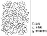
- each grain after discrimination can be displayed as shown in FIG.
- a visual inspection is performed using a grain identification dish called a carton as described in Patent Document 2.
- the visual inspection using the grain identification dish is evaluated as being capable of roughly discriminating at a glance with the grains put on the grain identification dish.
- the sample grain used for the inspection is stored as an image in a state of being put on a grain identification dish and It is desired to enable display.
- the sample grain after being imaged by an imaging device such as a scanner is placed on the grain identification dish, and the grain identification dish after the imaging is imaged by another imaging means (such as a digital camera) different from the imaging apparatus. It takes time and effort to store and display the image information in association with each other.
- an imaging device such as a scanner
- another imaging means such as a digital camera
- JP 2004-361333 A Japanese Patent No. 4716389
- the present invention inspects a grain using image information captured by an imaging device such as a scanner, and uses the image information to indicate a state in which the grain is put on a grain observation dish.
- an imaging device such as a scanner
- the image information to indicate a state in which the grain is put on a grain observation dish.
- the present invention provides an image pickup means for picking up a plurality of grains, an analysis means for analyzing image information of the grains picked up by the image pickup means in units of grains, and processing the image information.
- the processing means can obtain an image of the grain from the image information.
- the technical means of forming an aggregate image of the images of the grains by arranging the images of the grains of the extracted grains in close contact with each other (or in a dense state) It was.
- the processing means is provided with an area set value input unit, and from the area set value input unit, a set value for setting an area size of a portion where grains images overlap in the close state is input, and the size of the area Technical measures were taken to place an upper limit on the length.
- a technical means was provided in which an outer frame was provided on the collective image, and the shape of the outer frame was the same shape as the grain placement surface of the grain identification dish.
- the grain appearance measuring apparatus of the present invention can inspect the appearance of the grain by an optical technique, and is a collective image (pseudo image) representing a state in which the inspected grain is put into a grain identification dish used for visual inspection. Can be stored or displayed. As a result, it is possible to obtain a result of the optical inspection and at the same time perform a visual inspection using the grain identification dish by using the collective image in a pseudo manner.
- the upper limit is set so that the size of the area where the grain images overlap each other does not exceed a certain amount. It is possible to express the same overlap between grains.
- the collective image it is possible to easily create a collective image in a state where the image of the grains are in contact with each other without overlapping, and since there is no overlap between the images of the grains if the collective image, All images can be displayed.
- the outer frame of the aggregate image has the same shape as the grain placement surface of the grain identification dish, it is easy to perform a pseudo visual inspection using the aggregate image.
- the gap between the grains in the aggregate image is represented by a specific color such as blue, white, or black used for the grain identification dish, it is easy to perform a pseudo visual inspection using the aggregate image.
- FIG. 1 is a diagram showing a grain appearance measuring apparatus 1 according to the present invention.
- the grain appearance measuring apparatus 1 includes a computer 2 and a color scanner 3 as an “imaging device” connected to the computer 2.
- the computer 2 includes an analysis unit that analyzes image information, a processing unit that processes the image information, a storage unit that stores the image information, a display unit that displays the image information, a measurement result, image information, and the like via a network. Equipped with functions to distribute.
- the computer 2 also has a function of an area setting value input unit 27 described later.
- the color scanner 3 includes a scanner body 5 having an image reading surface 4 on the upper end surface, and a cover 6 that covers the image reading surface 4 of the scanner body 5 at the time of measurement.
- the image reading surface 4 is made of glass and is disposed on the upper surface of the scanner body 5.
- the image reading surface 4 is not limited to a glass plate, and an acrylic plate may be used, or a plate material made of a transparent material other than those may be used.
- a sample tray 20 is placed on the image reading surface 4 during measurement.
- a scanning device is disposed in the scanner body 5, and the scanning device irradiates the bottom surface of the sample tray 20 with light (light source) and the grain surface irradiated with the light irradiation unit. And a light receiving portion for receiving the reflected light reflected by the light.
- the light receiving unit of the scanning device is configured by a color CCD or the like, and receives reflected light from the grain placed on the image reading surface 4 for each of three colors of RGB (red, green and blue), for example.
- RGB red, green and blue
- One side of the cover 6 is hinged to one side of the upper end of the scanner body 5 and can be rotated by the hinge. At the time of measurement, the image reading surface 4 of the scanner main body 5 can be covered by the cover 6, and stray light from the outside can be prevented.
- a general scanner can be used as the color scanner 3.
- the sample tray 20 of the grain appearance measuring apparatus 1 of the present embodiment will be described.
- the sample tray 20 is formed in a rectangular frame shape in a plan view, and is easy to handle at two places on the bottom plate 21, a side wall raised upward from the periphery of the bottom plate 21, and the side wall. It is comprised by the holding part provided in this way.
- the bottom plate 21 is a transparent plate, and acrylic resin or the like is used. When the sample tray 20 is placed on the upper surface of the image reading surface 4, the bottom surface 21 is placed in contact with the upper surface of the image reading surface 4.
- a reference plate 22 may be provided in a part of the region surrounded by the side wall.
- the reference plate 22 is used to acquire image information for correcting the measurement value obtained by the color scanner 3.
- the position where the reference plate 22 is disposed is not particularly limited as long as it is within the region, and may be disposed at a location convenient for design. Further, the shape is not particularly limited, but a rectangular shape is easy to design.
- the reference plate 22 has a rectangular shape, and is arranged so that one end in the longitudinal direction of the reference plate 22 is in contact with the side wall.
- the reference plate 22 may be formed of only one color, it is desirable to configure it by combining two color reference plates such as white and black.
- the sample tray 20 is measured by the color scanner 3, it is considered that the reflected light from the main body of the sample tray 20 affects the measurement.
- at least the surface is preferably not glossy, and it is desirable to form the sample tray 20 with a black body or a material close to a black body.
- This embodiment demonstrates the case where the grain to be examined is brown rice.
- Approx. 1000 grains of brown rice 7 are put on the bottom surface 21 of the sample tray 20 so that the grains do not overlap each other.
- the sample tray 20 is placed on the image reading surface 4 of the color scanner 3 as shown in FIG.
- the bottom surface 21 of the sample tray 20 serves as an optical path.
- the number of grains to be measured in one measurement is not particularly limited, and may be increased or decreased freely within the range of the number that can be placed on the bottom surface of the sample tray.
- the upper surface of the sample tray 20 is covered with the cover 6, and an image of the brown rice 7 is taken using the color scanner 3.
- the scanning operation of the scanner main body 5 is moved (two-dimensional scanning) along the bottom surface of the image reading surface 4.
- light is irradiated to the brown rice 7 from the light irradiation part of a scanning device, and the reflected light reflected by the brown rice 7 is received by the light-receiving part of a scanning device.
- the received signal is output to the computer 2 as RGB image information.
- the brown rice 7 imaged by the color scanner 3 is imaged on the lower side of the grain, which is the surface in contact with the bottom surface 21.
- the computer 2 can store and display image information.
- FIG. 11 shows an example in which the image information is displayed on the computer 2.
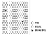
- the analysis by the computer 2 can use a general analysis method. For example, a method as described in JP 2011-242284 A can be used. Further, in this embodiment, the measurement is performed without aligning the brown rice, but for example, by performing image processing as described in CN101281112 (open publication) published in China, Each brown rice can be identified by grain. For this reason, as shown in FIG. 12, it can also be displayed in the state which aligned each image of the measured brown rice 7 per grain.
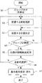
- FIG. 2 is a flowchart showing a procedure for creating a collective image.
- the measured grain is grouped by grain by the processing means of the computer 2 (step S1). Grouping may be performed according to the appearance of each grain, such as sized grains, colored grains, blue immature grains, pest-damaged grains, and crushed grains. In this embodiment, the case where it divides into three groups, a sized particle, a colored particle
- the grouping method is not particularly limited, and each measured grain may be color-coded in 256 stages and then divided into a plurality of groups.
- the image of the grain to be arranged is selected (step S2).
- a grain image it is only necessary to sequentially select each grain image of the image information extracted in units of grains. For example, in the image information shown in FIG. You should select in order from the upper left. An image of one grain is selected only once.
- the shape of the outer frame 25 of the aggregate image is preferably the same shape as the grain placement surface (bottom face) of the grain identification dish, and is usually round, but may be set freely such as a square. . In the present embodiment, the outer frame 25 is round.
- the size of the outer frame 25 may be the same as the grain placement surface of the actual grain identification dish, but may be reduced. In this case, the same reduction as the outer frame 25 is reduced. It is necessary to carry out for the image of the grain.
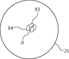
- FIG. 3 shows a collective image at the initial stage of creation.
- the first (first) grain image selected first can be freely arranged in the outer frame 25.
- the image of the grain selected after the second is arranged so that at least a part of the image of the already arranged grain is adjacent.
- the angle on the grain image at that time may be set freely.
- FIG. 3 shows a stage in which an image X 4 of the fourth grain is arranged in the outer frame 25.
- the grain image X4 is a sized image, and a part of the grain image X4 is arranged adjacent to the already-arranged grain image X3.
- the term “adjacent” between the kernel images in the present invention includes a state in which a part of the kernel images overlap.
- a group of kernels adjacent to the kernel image X4 is confirmed.
- the purpose of the present invention is to reproduce the image of the state in which the grain is put in the grain observation dish at the time of visual inspection. It is necessary to disperse and arrange in. For this reason, the sized particles may be in contact with each other, but the newly arranged grains at the time of arrangement in step S3 so that the colored grains, the pest damaged grains or the colored grains and the pest damaged grains are not placed in contact with each other.
- a group of arranged grain images adjacent to the grain image is confirmed (step S4). In FIG.
- step S3 and step S4 are separated, but group confirmation may also be performed at the time of step S3.
- Step S4 group confirmation
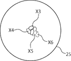
- FIG. 5 shows a state in which an image X6 of the sixth grain (colored grain) is arranged adjacent to an image X5 of the fifth grain (colored grain).
- the position (coordinates) where the image X6 of the grain is arranged is changed and rearranged at a position adjacent to the image of another grain, or The 6th arrangement of the image X6 is stopped, and an image of another grain (sized in this case) is selected from the image information (step S2).
- FIG. 5 shows a state in which an image X6 of the sixth grain (colored grain) is arranged adjacent to an image X5 of the fifth grain (colored grain).
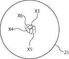
- FIG. 6 shows a case where the position where the grain image X6 is arranged is changed, and the position where the grain image X6 is arranged is adjacent to the grain images X3 and X4 which are sized. It has been changed to eliminate the adjacency between colored grains.
- step S3 it is confirmed whether the size of the area of the part where the newly arranged grain image overlaps the image of another arranged grain does not exceed the preset set value.
- the overlap of the area exceeding the set value it is necessary to adjust the position of the corresponding grain image in order to eliminate the overlap. In that case, the position of one or both of the image of the newly arranged grain and the image of the already arranged grain will be adjusted.
- the set value can be set by the size of the area where the two grain images overlap, but in this embodiment, the set value is set as a “ratio” with respect to the entire area of the part where the two grain images overlap. The ratio is obtained by “the area of the overlapping grain / the total area of the image of the grain”. Then, 25% is set as the ratio value. For this reason, the size of the area where the grain images overlap is allowed up to 25% of the total area of the grain images.
- the set value is input from an area set value input unit 27 provided in the computer 2.
- the size of the image of the kernel is also different for each image. Therefore, even if the area of the part where the image Y1 of the newly arranged grain overlaps the image of the arranged image Y2 is within the set value (ratio), the image of the arranged image Y2 of the arranged grain When the size is smaller than the image of the newly arranged grain image Y1, the ratio of the area of the part overlapping the grain image Y1 may exceed the set value for the grain Y2 image. . Therefore, also about the image of the already arranged grain, it is necessary to make the area of the part which overlaps with the image of the newly arranged grain not exceed the set value.
- the set image may be created by ignoring the portion overlapping the newly arranged kernel image, or the set value is set only on the image side of the already arranged kernel. The position adjustment may be omitted even when an excessive overlap occurs.
- the ratio of the area of the image of the newly arranged grain and the area of the portion where the image of the grain overlaps the image of the already arranged grain, or the already arranged grain does not need to be 25%, and can be freely set to 25% or less. What is necessary is just to determine a ratio for every grain.
- a plurality of setting values can be provided within a range of 0% to 25%, and the size of the overlap can be determined with an arbitrary setting value for each grain.
- setting values six setting values of 0%, 5%, 10%, 15%, 20% and 25% are provided, and an arbitrary setting value is selected for each grain at the time of arrangement in step S3, and a plurality of types It is preferable to reproduce the image of the grain on the collective image in the overlapping state.
- the upper limit of the set value is not limited to 25%, and an arbitrary value may be set at any time according to the purpose of the group image to be created.
- the width of the set value is not limited to 5%, and the width may be set as desired at any time according to the purpose of the group image to be created.
- a part of the grain image may protrude outside the outer frame 25.
- the size or ratio of the area where a part of the image of the grain may protrude outside the outer frame 25 is set as a setting value.
- the set value in that case may be set by the size or ratio of the area of the grain image of the part that protrudes outside the outer frame 25, and the ratio in the corresponding grain is “the portion of the part that protrudes outside the outer frame 25. What is necessary is just to obtain
- the setting value is 25% of the ratio. For this reason, even when a part of the image of the grain protrudes outside the outer frame 25, the ratio is allowed up to 25%.
- the set value is not limited to 25%, and may be changed as needed according to the purpose of the group image to be created. As in the case of overlapping grains images, the set value can be provided in a plurality of stages, and the area that protrudes outside the outer frame 25 can be set to an arbitrary size. When the set value is 0%, the grain image is not displayed outside the outer frame 25, and the outermost edge of the image is in contact with the outer frame 25.
- the image of one kernel is positioned above or below the image of the other kernel.
- this vertical relationship may be arbitrarily determined freely. The vertical relationship may be determined based on a specific law.
- step S5 the position (coordinates) of the grain image is adjusted as necessary.
- a process of reducing the gap ⁇ shown in FIG. 3 is performed (step S5).
- the kernel image X4 is rotated while maintaining the adjacency with the kernel image X3, and the position is adjusted so as to be adjacent to another kernel image X2.
- Reduce the gap ⁇ The visual grain inspection is performed in a state in which the grains are densely packed on the grain identification plate without any gaps, so that the gap reduction processing in step S5 is performed in order to represent the densely-grained grains in the aggregate image to be created. Is required.
- the image is adjacent to a plurality of kernel images (except for the initial stage of creating a collective image). For this reason, it is necessary to obtain the size or ratio of the area of the overlapping portion for each adjacent grain image.
- the said ratio in the image of a relevant grain is calculated
- the setting value in step S3 and the setting value in step S5 may be a common value, or may be managed by providing individual values.
- the set value in step S5 is also input from the area set value input unit 27 of the computer 2.
- step S5 even if the area of the part where the newly arranged grain image Z1 overlaps the already arranged grain image Z2 is within the set value (ratio), the arranged grain
- the ratio of the area of the portion overlapping the grain Z1 may exceed the set value for the image Z2 of the grain. . Therefore, also about the image of the already arranged grain, it is necessary to make the area of the part which overlaps with the image of the newly arranged grain not exceed the set value.
- the ratio or the size of the area of the part that overlaps with the newly arranged grain image is obtained, it is confirmed whether it exceeds the set value, and the set value is exceeded. In this case, it is necessary to adjust the position of the image of the newly arranged grain or the image of the arranged grain that overlaps the image of the grain.
- the set image may be created by ignoring the portion overlapping the newly arranged kernel image, or the set value is set only on the image side of the already arranged kernel. Position adjustment may be omitted even when excessive overlap occurs.
- step S5 25% is set as the value of the ratio in step S5. For this reason, the area of the part where the images of the grain overlap is allowed up to 25% of the total area of the image of the grain.
- step S5 it is not necessary that the area of the portion where the image of the grain to be adjusted overlaps with the image of the already arranged grain is 25%, and the ratio is freely set so that the area is 25% or less. You only have to decide every time. Further, a plurality of setting values may be provided in the range of 0% to 25%, and the overlap may be determined with an arbitrary setting value for each grain.
- setting values For example, six setting values of 0%, 5%, 10%, 15%, 20%, and 25% are provided as setting values, and arbitrary setting values are selected at the time of position adjustment in step S5, and a plurality of types of overlapping values are selected. It is preferable to reproduce the image of the grain on the aggregate image.
- the upper limit of the setting value is not limited to 25%, it is only necessary to set an arbitrary value according to the purpose of the collective image to be created, and the setting value width is not limited to 5%. The width may be set with an arbitrary value at any time according to the purpose of the collective image to be performed.
- the set value is 0%, the grain images are in contact with each other without overlapping.
- a set value is provided so as not to exceed the value so that an overlap exceeding the set value does not occur.
- step S5 The operations up to step S5 are repeated until all the grain images of the image information are arranged on the collective image.
- the created collective image is stored and / or displayed.
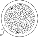
- FIG. 7 is a view showing a group image after creation. As shown in FIG. 8, an image using a plan view of the grain appraisal dish 26 may be created, stored, and / or displayed on the background of the collective image.
- the created aggregated image is not only displayed on the computer 2, but can also be viewed using the Internet, so that it can be used at the time of grain trading even in a remote place such as a foreign country.
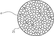
- FIG. 10 is a collective image in a state where the images of the grains are in contact with each other without overlapping.
- an aggregate image can be easily created by setting the setting value of the size or ratio of the overlap between the grain images to a minimum (0 or 0%).
- This image may be the final collective image.
- the gap ⁇ may be displayed and stored in an arbitrary color, but preferably the same color as the grain identification dish, such as blue, black, or white. Since the gap ⁇ is a background in the collective image, a color that can be easily inspected may be freely selected for each grain to be inspected.
- the color particles, the pest damage particles, or the color particles and the pest damage particles are set so as not to contact each other, but step S1 and step S4 are omitted, and the color particles, the pests are omitted.
- a collective image may be created in which damaged grains or colored grains and pest-damaged grains may contact each other.
- an image of a grain can be obtained in units of grains, it can be used as an imaging device of the present invention.
- each grain can also be implemented in an apparatus that conveys and images the image.
- the grain appearance measuring device of the present invention can inspect not only grains but also beans. Moreover, if it is granular things, such as resin pellets, it can be used for a test
Landscapes
- General Physics & Mathematics (AREA)
- Physics & Mathematics (AREA)
- Engineering & Computer Science (AREA)
- Theoretical Computer Science (AREA)
- Immunology (AREA)
- Biochemistry (AREA)
- General Health & Medical Sciences (AREA)
- Analytical Chemistry (AREA)
- Chemical & Material Sciences (AREA)
- Pathology (AREA)
- Life Sciences & Earth Sciences (AREA)
- Health & Medical Sciences (AREA)
- Quality & Reliability (AREA)
- Computer Vision & Pattern Recognition (AREA)
- Investigating Materials By The Use Of Optical Means Adapted For Particular Applications (AREA)
- Image Processing (AREA)
Abstract
Description
2 コンピュータ
3 カラースキャナ
4 画像読取面
5 スキャナ本体
6 カバー
7 玄米
20 試料トレー
21 底面
22 基準板
25 外枠
Claims (5)
- 複数の穀粒を撮像する撮像手段と、
該撮像手段により撮像された穀粒の画像情報を粒単位で分析する分析手段と、
前記画像情報を加工して前記穀粒の集合画像を形成する加工手段と、
前記集合画像を保存及び/又は表示する手段と
から構成された穀粒外観測定装置において、
前記加工手段は、
前記画像情報から穀粒の画像を粒単位で抽出し、抽出した粒単位の各穀粒の画像を互いに密接状態となるように配置して、前記穀粒の画像の集合画像を形成することを特徴とする穀粒外観測定装置。 - 前記加工手段に面積設定値入力部を設け、
該面積設定値入力部から、前記密接状態において穀粒の画像同士が重なる部分の面積の大きさを設定する設定値が入力されることを特徴とする請求項1に記載の穀粒外観測定装置。 - 前記加工手段は、前記面積設定値入力部に前記設定値の最小値が入力されることで、穀粒の画像同士が重なることなく接した状態の集合画像を形成することを特徴とする請求項2に記載の穀粒外観測定装置。
- 前記加工手段において、前記集合画像に穀粒鑑定皿の穀粒載置面と同一形状とした外枠を設けたことを特徴とする請求項1乃至3のいずれかに記載の穀粒外観測定装置。
- 前記加工手段にて形成する集合画像において、各穀粒の画像間に生じる隙間の部分を特定の色で表して保存及び/又は表示させることを特徴とする請求項1乃至3のいずれかに記載の穀粒外観測定装置。
Priority Applications (5)
| Application Number | Priority Date | Filing Date | Title |
|---|---|---|---|
| CN201380034156.5A CN104428657B (zh) | 2012-06-27 | 2013-05-16 | 谷粒外观测定装置 |
| IN59KON2015 IN2015KN00059A (ja) | 2012-06-27 | 2013-05-16 | |
| KR1020157002039A KR102037560B1 (ko) | 2012-06-27 | 2013-05-16 | 곡립 외관 측정 장치 |
| EP13809865.2A EP2869065A4 (en) | 2012-06-27 | 2013-05-16 | DEVICE FOR MEASURING THE APPEARANCE OF GRAINS |
| US14/411,099 US9607368B2 (en) | 2012-06-27 | 2013-05-16 | Grain appearance measuring apparatus |
Applications Claiming Priority (2)
| Application Number | Priority Date | Filing Date | Title |
|---|---|---|---|
| JP2012-143709 | 2012-06-27 | ||
| JP2012143709A JP6024949B2 (ja) | 2012-06-27 | 2012-06-27 | 穀粒外観測定装置 |
Publications (1)
| Publication Number | Publication Date |
|---|---|
| WO2014002636A1 true WO2014002636A1 (ja) | 2014-01-03 |
Family
ID=49782808
Family Applications (1)
| Application Number | Title | Priority Date | Filing Date |
|---|---|---|---|
| PCT/JP2013/063700 WO2014002636A1 (ja) | 2012-06-27 | 2013-05-16 | 穀粒外観測定装置 |
Country Status (8)
| Country | Link |
|---|---|
| US (1) | US9607368B2 (ja) |
| EP (1) | EP2869065A4 (ja) |
| JP (1) | JP6024949B2 (ja) |
| KR (1) | KR102037560B1 (ja) |
| CN (1) | CN104428657B (ja) |
| IN (1) | IN2015KN00059A (ja) |
| TW (1) | TWI585396B (ja) |
| WO (1) | WO2014002636A1 (ja) |
Cited By (1)
| Publication number | Priority date | Publication date | Assignee | Title |
|---|---|---|---|---|
| WO2015186708A1 (ja) * | 2014-06-05 | 2015-12-10 | 株式会社サタケ | 粒状物外観品位判別装置における品位判別基準の作成方法 |
Families Citing this family (4)
| Publication number | Priority date | Publication date | Assignee | Title |
|---|---|---|---|---|
| TWI632360B (zh) * | 2015-02-19 | 2018-08-11 | 高橋機械工程股份有限公司 | Pod screening system and pod screening device |
| CN108885178B (zh) * | 2016-02-22 | 2021-12-10 | 株式会社佐竹 | 粒状物外观品相判别装置 |
| CN108593548A (zh) * | 2018-03-07 | 2018-09-28 | 四川杰莱美科技有限公司 | 一种考种用标定托盘 |
| CN117412821A (zh) * | 2021-01-25 | 2024-01-16 | 检测技术有限公司 | 自动化颗粒检查 |
Citations (9)
| Publication number | Priority date | Publication date | Assignee | Title |
|---|---|---|---|---|
| JPH10104165A (ja) * | 1996-09-27 | 1998-04-24 | Kubota Corp | 撮像式の評価装置 |
| JP2001041895A (ja) * | 1999-07-30 | 2001-02-16 | Satake Eng Co Ltd | 粒状物品位判別装置 |
| JP2004361333A (ja) | 2003-06-06 | 2004-12-24 | Yamamoto Co Ltd | 粒状被検査物状態判別装置 |
| JP2006071552A (ja) * | 2004-09-03 | 2006-03-16 | Yamamoto Co Ltd | 粒状被検査物の状態判別装置 |
| JP2006200945A (ja) | 2005-01-18 | 2006-08-03 | Satake Corp | 穀粒品位判別装置 |
| CN101281112A (zh) | 2008-04-30 | 2008-10-08 | 浙江理工大学 | 一种对网状粘连稻米的图像式自动分析方法 |
| JP2009002844A (ja) * | 2007-06-22 | 2009-01-08 | Japan Grain Inspection Association | 穀類粒の品質評価システム及び品質評価方法 |
| JP4716389B1 (ja) | 2010-03-31 | 2011-07-06 | 株式会社ケット科学研究所 | 穀粒鑑定具 |
| WO2011145287A1 (ja) * | 2010-05-19 | 2011-11-24 | 株式会社サタケ | 穀粒外観品位判別装置における品位別重量比率の算出方法 |
Family Cites Families (10)
| Publication number | Priority date | Publication date | Assignee | Title |
|---|---|---|---|---|
| US4713781A (en) * | 1985-09-19 | 1987-12-15 | Deere & Company | Grain damage analyzer |
| US5917927A (en) * | 1997-03-21 | 1999-06-29 | Satake Corporation | Grain inspection and analysis apparatus and method |
| KR20000077034A (ko) * | 1999-04-22 | 2000-12-26 | 사따께 사또루 | 입상물의 품질을 평가하기 위한 장치 및 방법 |
| JP3935768B2 (ja) * | 2002-04-24 | 2007-06-27 | 大日本印刷株式会社 | 画像合成方法およびシステム |
| US7058335B2 (en) * | 2002-06-14 | 2006-06-06 | Ricoh Company, Ltd. | Process cartridge and image forming apparatus with toner fed cleaning mode |
| CN100460176C (zh) * | 2003-09-11 | 2009-02-11 | 三泽住宅株式会社 | 树脂成形品制造装置 |
| CN101109743B (zh) * | 2007-09-10 | 2011-05-04 | 肯特大学 | 基于数字图像处理技术的便携式谷类分析仪 |
| CN101788497B (zh) * | 2009-12-30 | 2013-05-29 | 深圳先进技术研究院 | 一种基于图像识别技术的嵌入式豆类分类系统 |
| CN201699810U (zh) * | 2010-06-25 | 2011-01-05 | 北京东孚久恒仪器技术有限公司 | 用于颗粒状物料图像采集的扫描仪 |
| TWM416988U (en) * | 2011-05-26 | 2011-12-01 | Univ Far East | Inspection structure of paddy machine |
-
2012
- 2012-06-27 JP JP2012143709A patent/JP6024949B2/ja active Active
-
2013
- 2013-05-16 IN IN59KON2015 patent/IN2015KN00059A/en unknown
- 2013-05-16 CN CN201380034156.5A patent/CN104428657B/zh active Active
- 2013-05-16 WO PCT/JP2013/063700 patent/WO2014002636A1/ja active Application Filing
- 2013-05-16 US US14/411,099 patent/US9607368B2/en active Active
- 2013-05-16 KR KR1020157002039A patent/KR102037560B1/ko active IP Right Grant
- 2013-05-16 EP EP13809865.2A patent/EP2869065A4/en not_active Withdrawn
- 2013-06-21 TW TW102122192A patent/TWI585396B/zh active
Patent Citations (10)
| Publication number | Priority date | Publication date | Assignee | Title |
|---|---|---|---|---|
| JPH10104165A (ja) * | 1996-09-27 | 1998-04-24 | Kubota Corp | 撮像式の評価装置 |
| JP2001041895A (ja) * | 1999-07-30 | 2001-02-16 | Satake Eng Co Ltd | 粒状物品位判別装置 |
| JP2004361333A (ja) | 2003-06-06 | 2004-12-24 | Yamamoto Co Ltd | 粒状被検査物状態判別装置 |
| JP2006071552A (ja) * | 2004-09-03 | 2006-03-16 | Yamamoto Co Ltd | 粒状被検査物の状態判別装置 |
| JP2006200945A (ja) | 2005-01-18 | 2006-08-03 | Satake Corp | 穀粒品位判別装置 |
| JP2009002844A (ja) * | 2007-06-22 | 2009-01-08 | Japan Grain Inspection Association | 穀類粒の品質評価システム及び品質評価方法 |
| CN101281112A (zh) | 2008-04-30 | 2008-10-08 | 浙江理工大学 | 一种对网状粘连稻米的图像式自动分析方法 |
| JP4716389B1 (ja) | 2010-03-31 | 2011-07-06 | 株式会社ケット科学研究所 | 穀粒鑑定具 |
| WO2011145287A1 (ja) * | 2010-05-19 | 2011-11-24 | 株式会社サタケ | 穀粒外観品位判別装置における品位別重量比率の算出方法 |
| JP2011242284A (ja) | 2010-05-19 | 2011-12-01 | Satake Corp | 穀粒外観品位判別装置における品位別重量比率の算出方法 |
Non-Patent Citations (1)
| Title |
|---|
| See also references of EP2869065A4 |
Cited By (6)
| Publication number | Priority date | Publication date | Assignee | Title |
|---|---|---|---|---|
| WO2015186708A1 (ja) * | 2014-06-05 | 2015-12-10 | 株式会社サタケ | 粒状物外観品位判別装置における品位判別基準の作成方法 |
| JP2015230265A (ja) * | 2014-06-05 | 2015-12-21 | 株式会社サタケ | 粒状物外観品位判別装置における品位判別基準の作成方法 |
| KR20170015338A (ko) * | 2014-06-05 | 2017-02-08 | 가부시끼가이샤 사따께 | 입상물 외관 품위 판별 장치에 있어서의 품위 판별 기준의 작성 방법 |
| CN106662534A (zh) * | 2014-06-05 | 2017-05-10 | 株式会社佐竹 | 粒状物外观等级判别装置的等级判别基准的生成方法 |
| US10386307B2 (en) | 2014-06-05 | 2019-08-20 | Satake Corporation | Method of creating quality grade discrimination criteria in granular material appearance quality grade discrimination device |
| KR102382399B1 (ko) * | 2014-06-05 | 2022-04-01 | 가부시끼가이샤 사따께 | 입상물 외관 품위 판별 장치에 있어서의 품위 판별 기준의 작성 방법 |
Also Published As
| Publication number | Publication date |
|---|---|
| JP6024949B2 (ja) | 2016-11-16 |
| TW201415005A (zh) | 2014-04-16 |
| US20150146938A1 (en) | 2015-05-28 |
| JP2014006215A (ja) | 2014-01-16 |
| EP2869065A4 (en) | 2016-02-17 |
| KR102037560B1 (ko) | 2019-10-28 |
| US9607368B2 (en) | 2017-03-28 |
| TWI585396B (zh) | 2017-06-01 |
| KR20150036203A (ko) | 2015-04-07 |
| CN104428657A (zh) | 2015-03-18 |
| CN104428657B (zh) | 2016-11-09 |
| EP2869065A1 (en) | 2015-05-06 |
| IN2015KN00059A (ja) | 2015-07-31 |
Similar Documents
| Publication | Publication Date | Title |
|---|---|---|
| WO2014002636A1 (ja) | 穀粒外観測定装置 | |
| JP6590907B2 (ja) | 莢果選別システム、莢果選別装置及び莢果選別方法 | |
| CN106596073A (zh) | 一种检测光学系统像质的方法和系统及一种测试标板 | |
| CN102782481B (zh) | 谷粒外观品质判别装置的按品质划分的重量比率的计算方法 | |
| JP5009663B2 (ja) | 外観検査システム | |
| WO2007074770A1 (ja) | 画像解析によって欠陥検査を行う欠陥検査装置 | |
| US10386307B2 (en) | Method of creating quality grade discrimination criteria in granular material appearance quality grade discrimination device | |
| JP4590553B2 (ja) | 生籾被害粒の非破壊判定方法 | |
| US20140367555A1 (en) | Image measurement apparatus and image measurement method | |
| JP2019203701A (ja) | パック詰めされた卵の検査装置 | |
| JP2001041895A (ja) | 粒状物品位判別装置 | |
| JP3333472B2 (ja) | 褐色鶏卵における血卵の非破壊検出方法とその装置 | |
| JP2015001441A (ja) | 米粒の白濁部位等の詳細判別システム、詳細判別プログラム及び記憶媒体 | |
| JP2021092439A (ja) | 照明最適化方法、制御装置、及びプログラム | |
| JP6765643B2 (ja) | 穀類の搗精度評価方法及びその装置 | |
| KR101030451B1 (ko) | 원통형 이차 전지 튜브 및 와셔 검사 장치 | |
| JP6748941B2 (ja) | 穀粒外観測定装置 | |
| JP2003251282A (ja) | 苺用等階級計測判定装置 | |
| JP6004156B2 (ja) | 穀粒外観品位判別装置 | |
| JP2017150823A (ja) | 粒状物外観品位判別装置 | |
| US11906439B2 (en) | Optical inspection method, non-transitory storage medium storing optical inspection program, and optical inspection apparatus | |
| CN108885178B (zh) | 粒状物外观品相判别装置 | |
| JP6948032B2 (ja) | 画像解析装置および検査システム | |
| JP3618311B2 (ja) | 穀粒品質判定装置 | |
| JP3168410B2 (ja) | 乾海苔の品質検査方法 |
Legal Events
| Date | Code | Title | Description |
|---|---|---|---|
| 121 | Ep: the epo has been informed by wipo that ep was designated in this application |
Ref document number: 13809865 Country of ref document: EP Kind code of ref document: A1 |
|
| WWE | Wipo information: entry into national phase |
Ref document number: 14411099 Country of ref document: US |
|
| NENP | Non-entry into the national phase |
Ref country code: DE |
|
| WWE | Wipo information: entry into national phase |
Ref document number: 2013809865 Country of ref document: EP |
|
| ENP | Entry into the national phase |
Ref document number: 20157002039 Country of ref document: KR Kind code of ref document: A |