以下、図面を参照しながら詳細に説明する。図1は本発明に係る穀粒外観測定装置1を示した図である。
Hereinafter, detailed description will be given with reference to the drawings. FIG. 1 is a diagram showing a grain appearance measuring apparatus 1 according to the present invention.
図1に示されるように、穀粒外観測定装置1は、コンピュータ2と、コンピュータ2に接続された「撮像装置」としてのカラースキャナ3とを含んで構成されている。
As shown in FIG. 1, the grain appearance measuring apparatus 1 includes a computer 2 and a color scanner 3 as an “imaging device” connected to the computer 2.
コンピュータ2には、画像情報を分析する分析手段、前記画像情報を加工する加工手段、前記画像情報を保存する保存手段、前記画像情報を表示する表示手段、測定結果や画像情報等をネットワーク経由で配信する機能等が装備されている。コンピュータ2には後述する面積設定値入力部27の機能も備えられている。
The computer 2 includes an analysis unit that analyzes image information, a processing unit that processes the image information, a storage unit that stores the image information, a display unit that displays the image information, a measurement result, image information, and the like via a network. Equipped with functions to distribute. The computer 2 also has a function of an area setting value input unit 27 described later.
カラースキャナ3は、画像読取面4を上端面に有するスキャナ本体5と、このスキャナ本体5の画像読取面4を測定時に覆うカバー6とから構成されている。
The color scanner 3 includes a scanner body 5 having an image reading surface 4 on the upper end surface, and a cover 6 that covers the image reading surface 4 of the scanner body 5 at the time of measurement.
画像読取面4はガラス製であって、スキャナ本体5の上面に配設されている。画像読取面4はガラス板に限定されるわけではなく、アクリル板を使用してもよいし、それら以外の透明材料からなる板材を使用してもよい。画像読取面4には、測定時に試料トレー20が載置される。
The image reading surface 4 is made of glass and is disposed on the upper surface of the scanner body 5. The image reading surface 4 is not limited to a glass plate, and an acrylic plate may be used, or a plate material made of a transparent material other than those may be used. A sample tray 20 is placed on the image reading surface 4 during measurement.
スキャナ本体5内には、走査装置が配設されており、走査装置は、試料トレー20の底面に対して光を照射する光照射部(光源)と、光照射部から照射されて穀粒表面で反射された反射光を受光する受光部とから構成されている。
A scanning device is disposed in the scanner body 5, and the scanning device irradiates the bottom surface of the sample tray 20 with light (light source) and the grain surface irradiated with the light irradiation unit. And a light receiving portion for receiving the reflected light reflected by the light.
走査装置の受光部は、カラーCCD等で構成されており、画像読取面4に載置された穀粒からの反射光を例えばRGBの三色(赤色、緑色及び青色)の光毎に受光し、受光して得られた画像情報をコンピュータ2に出力するようになっている。
The light receiving unit of the scanning device is configured by a color CCD or the like, and receives reflected light from the grain placed on the image reading surface 4 for each of three colors of RGB (red, green and blue), for example. The image information obtained by receiving the light is output to the computer 2.
カバー6の一辺はスキャナ本体5の上端一辺にヒンジ結合され、ヒンジにより回動可能である。測定時にはカバー6によってスキャナ本体5の画像読取面4をカバーすることができ、外部からの迷光を防止することができる。カラースキャナ3には一般的なスキャナを用いることができる。
の 一 One side of the cover 6 is hinged to one side of the upper end of the scanner body 5 and can be rotated by the hinge. At the time of measurement, the image reading surface 4 of the scanner main body 5 can be covered by the cover 6, and stray light from the outside can be prevented. A general scanner can be used as the color scanner 3.
本実施形態の穀粒外観測定装置1の試料トレー20について説明する。図示しているように、試料トレー20は、平面視で矩形枠状に形成され、底板21と、この底板21の周辺部から上方に立ち上げられた側壁と、該側壁の二箇所に取り扱いやすいように設けられた把持部とによって構成されている。底板21は、透明な板であって、アクリル樹脂等が用いられる。試料トレー20が画像読取面4の上面に載置された状態では、画像読取面4の上面に底面21が当接状態で載置されるようになっている。
The sample tray 20 of the grain appearance measuring apparatus 1 of the present embodiment will be described. As shown in the drawing, the sample tray 20 is formed in a rectangular frame shape in a plan view, and is easy to handle at two places on the bottom plate 21, a side wall raised upward from the periphery of the bottom plate 21, and the side wall. It is comprised by the holding part provided in this way. The bottom plate 21 is a transparent plate, and acrylic resin or the like is used. When the sample tray 20 is placed on the upper surface of the image reading surface 4, the bottom surface 21 is placed in contact with the upper surface of the image reading surface 4.
側壁に囲まれた領域の一部分には、基準板22を設けてもよい。基準板22は、カラースキャナ3での測定値を補正するための画像情報を取得するためのものである。基準板22を配置する位置は、前記領域内であれば特に限定されることはなく、設計上都合の良い箇所に配置すればよい。また、形状についても特に限定されることはないが、矩形状とするのが設計が行いやすい。本実施形態では、基準板22の形状を矩形状とし、基準板22の長手方向の一端を側壁に接するように配置している。基準板22は、一つの色のみで形成してもよいが、例えば白と黒等の、2色の基準板を組み合わせて構成することが望ましい。
A reference plate 22 may be provided in a part of the region surrounded by the side wall. The reference plate 22 is used to acquire image information for correcting the measurement value obtained by the color scanner 3. The position where the reference plate 22 is disposed is not particularly limited as long as it is within the region, and may be disposed at a location convenient for design. Further, the shape is not particularly limited, but a rectangular shape is easy to design. In the present embodiment, the reference plate 22 has a rectangular shape, and is arranged so that one end in the longitudinal direction of the reference plate 22 is in contact with the side wall. Although the reference plate 22 may be formed of only one color, it is desirable to configure it by combining two color reference plates such as white and black.
試料トレー20は、カラースキャナ3で測定を行うので、試料トレー20本体からの反射光が前記測定時に影響することが考えられる。反射光による影響を防ぐため、少なくとも表面は光沢がないことが好ましく、黒体若しくは黒体に近い素材で試料トレー20を形成することが望ましい。
Since the sample tray 20 is measured by the color scanner 3, it is considered that the reflected light from the main body of the sample tray 20 affects the measurement. In order to prevent the influence of reflected light, at least the surface is preferably not glossy, and it is desirable to form the sample tray 20 with a black body or a material close to a black body.
本実施形態の作用及び効果について説明する。本実施形態では検査対象の穀粒が玄米である場合について説明する。
The operation and effect of this embodiment will be described. This embodiment demonstrates the case where the grain to be examined is brown rice.
試料トレー20の底面21上に、約千粒の玄米7を粒同士がそれぞれ重ならないように投入する。投入後、図1に示すように、試料トレー20をカラースキャナ3の画像読取面4上に載置する。カラースキャナ3での測定時には、試料トレー20の底面21が光路となるので、指等と接触して底面21に汚れが付着することは好ましくない。なお、一回の測定で測定する穀粒の個数は、特に限定されることはなく、試料トレーの底面に載置可能な個数の範囲で自由に増減すればよい。
Approx. 1000 grains of brown rice 7 are put on the bottom surface 21 of the sample tray 20 so that the grains do not overlap each other. After the loading, the sample tray 20 is placed on the image reading surface 4 of the color scanner 3 as shown in FIG. At the time of measurement with the color scanner 3, the bottom surface 21 of the sample tray 20 serves as an optical path. The number of grains to be measured in one measurement is not particularly limited, and may be increased or decreased freely within the range of the number that can be placed on the bottom surface of the sample tray.
試料トレー20を載置した後は、カバー6で試料トレー20の上面をカバーし、カラースキャナ3を用いて玄米7の画像を撮像する。具体的な撮像動作は、スキャナ本体5の走査装置を、画像読取面4の底面に沿って移動(二次元走査)させる。その際に、走査装置の光照射部から玄米7へ光が照射され、玄米7で反射した反射光が走査装置の受光部に受光される。受光した信号は、RGBの画像情報としてコンピュータ2に出力される。カラースキャナ3で撮像する玄米7は、底面21に接する面である、粒の下側が撮像される。
After the sample tray 20 is placed, the upper surface of the sample tray 20 is covered with the cover 6, and an image of the brown rice 7 is taken using the color scanner 3. Specifically, the scanning operation of the scanner main body 5 is moved (two-dimensional scanning) along the bottom surface of the image reading surface 4. In that case, light is irradiated to the brown rice 7 from the light irradiation part of a scanning device, and the reflected light reflected by the brown rice 7 is received by the light-receiving part of a scanning device. The received signal is output to the computer 2 as RGB image information. The brown rice 7 imaged by the color scanner 3 is imaged on the lower side of the grain, which is the surface in contact with the bottom surface 21.
画像情報をコンピュータ2で解析することにより、測定した玄米の外観(整粒、砕米、死米、着色米、青未熟米、害虫被害米等)を光学的に高精度で検査し判別することができる。コンピュータ2において、画像情報を保存及び表示可能である。図11は、前記画像情報をコンピュータ2で表示する場合の一例を示している。
By analyzing the image information with the computer 2, it is possible to optically inspect and discriminate the measured appearance of brown rice (sized, crushed rice, dead rice, colored rice, green immature rice, pest-damaged rice, etc.). it can. The computer 2 can store and display image information. FIG. 11 shows an example in which the image information is displayed on the computer 2.
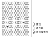
コンピュータ2での解析は、一般的な解析手法を用いることができる。例えば、特開2011-242284号公報に記載されているような方法を用いることができる。また、本実施例では、玄米を整列させることなく測定を行っているが、例えば、中国にて公開されているCN101281112号公報(公開公報)に記載されているような画像処理を行うことで、各玄米を粒単位で識別させることが可能である。このため、図12に示すように、測定した玄米7のそれぞれの画像を粒単位で整列させた状態で表示させることもできる。
The analysis by the computer 2 can use a general analysis method. For example, a method as described in JP 2011-242284 A can be used. Further, in this embodiment, the measurement is performed without aligning the brown rice, but for example, by performing image processing as described in CN101281112 (open publication) published in China, Each brown rice can be identified by grain. For this reason, as shown in FIG. 12, it can also be displayed in the state which aligned each image of the measured brown rice 7 per grain.
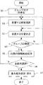
前記画像情報を使用して、穀粒観察皿上に穀粒を投入した集合画像(疑似画像)を作成する方法について説明する。図2は、集合画像作成の手順を示したフロー図である。
A method of creating a collective image (pseudo image) in which the grain is thrown on the grain observation dish using the image information will be described. FIG. 2 is a flowchart showing a procedure for creating a collective image.
まず、前記コンピュータ2の加工手段によって、測定した穀粒を粒単位でグループ分け(ステップS1)する。グループ分けは、整粒、着色粒、青未熟粒、害虫被害粒、砕粒等の各穀粒の外観で行えばよい。本実施形態では、説明を容易にするため、整粒、着色粒及び害虫被害粒の3つのグループに分けた場合について説明する。グループ分けの方法は特に限定されることはなく、測定した各穀粒を256段階で色分けしてから複数のグループに分けるようにしてもよい。
First, the measured grain is grouped by grain by the processing means of the computer 2 (step S1). Grouping may be performed according to the appearance of each grain, such as sized grains, colored grains, blue immature grains, pest-damaged grains, and crushed grains. In this embodiment, the case where it divides into three groups, a sized particle, a colored particle | grain, and a pest damage particle | grain is demonstrated in order to demonstrate easily. The grouping method is not particularly limited, and each measured grain may be color-coded in 256 stages and then divided into a plurality of groups.
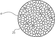
ステップS1にてグループ分けされた各穀粒の画像を、作成する集合画像の外枠25の内側に順に配置するために、配置する穀粒の画像を選択する(ステップS2)。穀粒の画像の選択においては、粒単位で抽出されている前記画像情報の各穀粒の画像を順に一つずつ選択していけばよく、例えば、図12で示された画像情報では、図の左上から順に選択していけばよい。一つの穀粒の画像が選択されるのは一度のみである。集合画像の外枠25の形状は、穀粒鑑定皿の穀粒載置面(底面)と同一の形状とすることが好ましく、通常は丸形であるが、四角形等、自由に設定すればよい。本実施形態では、外枠25を丸形としている。
In order to arrange the image of each grain grouped in step S1 in order inside the outer frame 25 of the aggregate image to be created, the image of the grain to be arranged is selected (step S2). In selecting a grain image, it is only necessary to sequentially select each grain image of the image information extracted in units of grains. For example, in the image information shown in FIG. You should select in order from the upper left. An image of one grain is selected only once. The shape of the outer frame 25 of the aggregate image is preferably the same shape as the grain placement surface (bottom face) of the grain identification dish, and is usually round, but may be set freely such as a square. . In the present embodiment, the outer frame 25 is round.
前記外枠25の大きさは、実物の穀粒鑑定皿の穀粒載置面と同一とすればよいが、縮小してもよく、その際は、外枠25を縮小したのと同一の縮小を穀粒の画像についても行う必要がある。
The size of the outer frame 25 may be the same as the grain placement surface of the actual grain identification dish, but may be reduced. In this case, the same reduction as the outer frame 25 is reduced. It is necessary to carry out for the image of the grain.
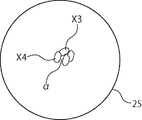
次に、ステップS2にて選択された穀粒の画像を配置する位置(座標)を決定するステップS3について説明する。図3は、作成初期段階の集合画像を表している。最初に選択された一つ目(1番目)の穀粒の画像は、外枠25内に自由に配置することができる。2番目以降に選択された穀粒の画像は、既に配置済みの穀粒の画像と少なくとも一部が隣接するように配置する。その際の穀粒の画像上の角度は自由に設定すればよい。図3は、外枠25内に4番目の穀粒の画像X4を配置する段階を示している。穀粒の画像X4は整粒の画像であって、その一部分が既に配置済みの穀粒の画像X3に少し重なった状態で隣接して配置されている。本発明における穀粒の画像同士の「隣接」という用語には、穀粒の画像の一部分が重なった状態も含まれるものとする。
Next, step S3 for determining the position (coordinates) for arranging the image of the grain selected in step S2 will be described. FIG. 3 shows a collective image at the initial stage of creation. The first (first) grain image selected first can be freely arranged in the outer frame 25. The image of the grain selected after the second is arranged so that at least a part of the image of the already arranged grain is adjacent. The angle on the grain image at that time may be set freely. FIG. 3 shows a stage in which an image X 4 of the fourth grain is arranged in the outer frame 25. The grain image X4 is a sized image, and a part of the grain image X4 is arranged adjacent to the already-arranged grain image X3. The term “adjacent” between the kernel images in the present invention includes a state in which a part of the kernel images overlap.
穀粒の画像X4の配置後、穀粒の画像X4が隣接している穀粒のグループを確認する。本発明では、目視での検査時に穀粒観察皿に穀粒が投入された状態の画像を疑似的に再現することを目的としているため、整粒以外の着色粒や害虫被害粒を前記集合画像内に分散させて配置する必要がある。このため、整粒同士は接触していてもよいが、着色粒同士、害虫被害粒同士又は着色粒と害虫被害粒とが接触して配置されないように、ステップS3における配置時に新たに配置する穀粒の画像が隣接する配置済みの穀粒の画像のグループを確認する(ステップS4)。図3においては、穀粒の画像X4が整粒、着色粒及び害虫被害粒のいずれとも隣接可能な整粒であるので、穀粒の画像X4をこの位置に配置しても問題はない。本実施形態ではステップS3とステップS4とを分けているが、ステップS3の時点でグループの確認も行うようにしてもよい。
After the arrangement of the kernel image X4, a group of kernels adjacent to the kernel image X4 is confirmed. The purpose of the present invention is to reproduce the image of the state in which the grain is put in the grain observation dish at the time of visual inspection. It is necessary to disperse and arrange in. For this reason, the sized particles may be in contact with each other, but the newly arranged grains at the time of arrangement in step S3 so that the colored grains, the pest damaged grains or the colored grains and the pest damaged grains are not placed in contact with each other. A group of arranged grain images adjacent to the grain image is confirmed (step S4). In FIG. 3, since the grain image X4 is sized so as to be adjacent to any of the sized, colored and pest-damaged grains, there is no problem even if the grain image X4 is arranged at this position. In this embodiment, step S3 and step S4 are separated, but group confirmation may also be performed at the time of step S3.
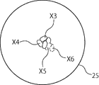
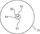
ステップS4(グループの確認)について、図5及び図6を用いて説明する。図5は、5番目の穀粒(着色粒)の画像X5に、6番目の穀粒(着色粒)の画像X6が隣接して配置された状態を示している。この場合、着色粒同士が隣接することになるので、穀粒の画像X6の配置する位置(座標)を変更して別の穀粒の画像と隣接する位置に配置し直すか、又は穀粒の画像X6の6番目での配置を中止し、前記画像情報から別の穀粒(この場合は整粒)の画像を選択(ステップS2)することになる。図6では、穀粒の画像X6の配置する位置を変更した場合を示しており、穀粒の画像X6が配置される位置が、整粒である穀粒の画像X3及びX4と隣接する位置に変更され、着色粒同士の隣接が解消されている。
Step S4 (group confirmation) will be described with reference to FIGS. FIG. 5 shows a state in which an image X6 of the sixth grain (colored grain) is arranged adjacent to an image X5 of the fifth grain (colored grain). In this case, since the colored grains are adjacent to each other, the position (coordinates) where the image X6 of the grain is arranged is changed and rearranged at a position adjacent to the image of another grain, or The 6th arrangement of the image X6 is stopped, and an image of another grain (sized in this case) is selected from the image information (step S2). FIG. 6 shows a case where the position where the grain image X6 is arranged is changed, and the position where the grain image X6 is arranged is adjacent to the grain images X3 and X4 which are sized. It has been changed to eliminate the adjacency between colored grains.
前記ステップS3における配置時に、新たに配置した穀粒の画像が、配置済みの別の穀粒の画像と重なる部分の面積の大きさが、事前に設定した設定値を超えていないかを確認し、前記設定値を超えた大きさの面積の重なりが確認された場合は、その重なりを解消するために該当する穀粒の画像の位置を調整する必要がある。その際は、新たに配置する穀粒の画像又は既に配置済みの穀粒の画像のどちらか一方、若しくは両方の位置を調整することになる。
At the time of the arrangement in step S3, it is confirmed whether the size of the area of the part where the newly arranged grain image overlaps the image of another arranged grain does not exceed the preset set value. When the overlap of the area exceeding the set value is confirmed, it is necessary to adjust the position of the corresponding grain image in order to eliminate the overlap. In that case, the position of one or both of the image of the newly arranged grain and the image of the already arranged grain will be adjusted.
設定値は、二つの穀粒の画像が重なる部分の面積の大きさで設定することができるが、本実施形態では、二つの穀粒の画像が重なる部分の面積の全体に対する「割合」で設定しており、その割合は「穀粒の重なっている部分の面積/穀粒の画像の全面積」で求めている。そして、前記割合の値として25%を設定値としている。このため、穀粒の画像同士が重なる部分の面積の大きさは、穀粒の画像の全面積の25%までは許容される。設定値はコンピュータ2に設けられた面積設定値入力部27から入力される。
The set value can be set by the size of the area where the two grain images overlap, but in this embodiment, the set value is set as a “ratio” with respect to the entire area of the part where the two grain images overlap. The ratio is obtained by “the area of the overlapping grain / the total area of the image of the grain”. Then, 25% is set as the ratio value. For this reason, the size of the area where the grain images overlap is allowed up to 25% of the total area of the grain images. The set value is input from an area set value input unit 27 provided in the computer 2.
穀粒の大きさは穀粒毎に異なるので、穀粒の画像の大きさも画像毎に異なることになる。したがって、新たに配置する穀粒の画像Y1が配置済みの穀粒の画像Y2の画像と重なる部分の面積が設定値(割合)以内であっても、配置済みの穀粒の画像Y2の画像の大きさが、新たに配置する穀粒の画像Y1の画像よりも小さい場合、穀粒Y2の画像については、穀粒の画像Y1と重なる部分の面積の割合が、設定値を超えることがあり得る。よって、既に配置済みの穀粒の画像についても、新たに配置される穀粒の画像と重なる部分の面積が設定値を超えないようにする必要がある。既に配置済みの穀粒の画像についても、新たに配置される穀粒の画像と重なる部分の面積の大きさ又は割合を求め、前記設定値を超えていないかを確認し、設定値を超えている場合には、新たに配置する穀粒の画像又は該穀粒と重なる配置済みの穀粒の画像の位置調整をする必要がある。配置済みの穀粒の画像については、新たに配置される穀粒の画像と重なる部分を無視して集合画像を作成してもよいし、既に配置済みの穀粒の画像側にのみ設定値を超えた重なりが生じた場合であっても前記位置調整を省略してもよい。
Since the size of the kernel is different for each kernel, the size of the image of the kernel is also different for each image. Therefore, even if the area of the part where the image Y1 of the newly arranged grain overlaps the image of the arranged image Y2 is within the set value (ratio), the image of the arranged image Y2 of the arranged grain When the size is smaller than the image of the newly arranged grain image Y1, the ratio of the area of the part overlapping the grain image Y1 may exceed the set value for the grain Y2 image. . Therefore, also about the image of the already arranged grain, it is necessary to make the area of the part which overlaps with the image of the newly arranged grain not exceed the set value. Also about the image of the already arranged grain, obtain the size or ratio of the area of the part that overlaps the newly arranged grain image, check whether it exceeds the set value, and exceed the set value If there is, it is necessary to adjust the position of the image of the newly arranged grain or the image of the arranged grain that overlaps with the grain. As for the image of the already arranged kernel, the set image may be created by ignoring the portion overlapping the newly arranged kernel image, or the set value is set only on the image side of the already arranged kernel. The position adjustment may be omitted even when an excessive overlap occurs.
前記ステップS3の配置時において、新たに配置する穀粒の画像の面積と該穀粒の画像が既に配置されている穀粒の画像と重なる部分の面積との割合、又は既に配置されている穀粒の画像の面積と該穀粒の画像が新たに配置される穀粒の画像と重なる部分の面積との割合は、全て25%とする必要はなく、25%以下となるように自由に前記割合を穀粒毎に決めればよい。0%~25%の範囲内で複数段階の設定値を設け、穀粒毎に任意の設定値で重なりの大きさを決定することもできる。設定値として、0%、5%、10%、15%、20%及び25%の6個の設定値を設け、ステップS3の配置時に穀粒毎に任意の設定値を選択し、複数種類の重なり具合で穀粒の画像を集合画像上で再現するようにすることが好ましい。設定値の上限は25%に限定されるわけでなく、作成する集合画像の目的に合わせて随時任意の値を設定すればよい。前記設定値の幅も5%に限定されるわけでなく、作成する集合画像の目的に合わせて随時任意の値で前記幅を設定すればよい。設定値が0%の場合は、穀粒の画像同士が重なりなく接することになる。
At the time of the arrangement in step S3, the ratio of the area of the image of the newly arranged grain and the area of the portion where the image of the grain overlaps the image of the already arranged grain, or the already arranged grain The ratio of the area of the image of the grain and the area of the portion where the image of the grain overlaps with the newly arranged grain image does not need to be 25%, and can be freely set to 25% or less. What is necessary is just to determine a ratio for every grain. A plurality of setting values can be provided within a range of 0% to 25%, and the size of the overlap can be determined with an arbitrary setting value for each grain. As setting values, six setting values of 0%, 5%, 10%, 15%, 20% and 25% are provided, and an arbitrary setting value is selected for each grain at the time of arrangement in step S3, and a plurality of types It is preferable to reproduce the image of the grain on the collective image in the overlapping state. The upper limit of the set value is not limited to 25%, and an arbitrary value may be set at any time according to the purpose of the group image to be created. The width of the set value is not limited to 5%, and the width may be set as desired at any time according to the purpose of the group image to be created. When the set value is 0%, the grain images are in contact with each other without overlapping.
ステップS3の配置時において、穀粒の画像の一部分が外枠25の外側にはみ出る場合がある。その場合は、穀粒の画像の一部分が外枠25の外側にはみ出てよい面積の大きさ又は割合を設定値として設定して対応する。その場合の設定値は、外枠25の外側にはみ出る部分の穀粒の画像の面積の大きさ又は割合で設定すればよく、該当する穀粒における割合は「外枠25の外側にはみ出る部分の面積/穀粒の画像の全面積」で求めればよい。本実施形態では、割合の25%を設定値としている。このため、穀粒の画像の一部分が外枠25の外側にはみ出る場合であっても前記割合が25%までは許容されることになる。設定値は25%に限定されるわけではなく、作成する集合画像の目的に合わせて随時変更すればよい。穀粒の画像同士の重なりの場合と同様に、前記設定値を複数段階で設け、外枠25の外側にはみ出る面積を、任意の大きさに設定することも可能である。設定値が0%の場合は、穀粒の画像が外枠25の外側に表示されることはなく、前記画像の最外縁が外枠25と接することになる。
At the time of arrangement in step S3, a part of the grain image may protrude outside the outer frame 25. In that case, the size or ratio of the area where a part of the image of the grain may protrude outside the outer frame 25 is set as a setting value. The set value in that case may be set by the size or ratio of the area of the grain image of the part that protrudes outside the outer frame 25, and the ratio in the corresponding grain is “the portion of the part that protrudes outside the outer frame 25. What is necessary is just to obtain | require by "Area / Total area of the image of a grain". In this embodiment, the setting value is 25% of the ratio. For this reason, even when a part of the image of the grain protrudes outside the outer frame 25, the ratio is allowed up to 25%. The set value is not limited to 25%, and may be changed as needed according to the purpose of the group image to be created. As in the case of overlapping grains images, the set value can be provided in a plurality of stages, and the area that protrudes outside the outer frame 25 can be set to an arbitrary size. When the set value is 0%, the grain image is not displayed outside the outer frame 25, and the outermost edge of the image is in contact with the outer frame 25.
穀粒の画像同士のその一部分を重ねる場合、一方の穀粒の画像がもう一方の穀粒の画像の上側又は下側に位置することになる。穀粒の画像同士を重ねる場合、どちらを上側又は下側にするかの前記画像の上下関係を決定する必要があるが、この上下関係は、任意で自由に決定すればよい。特定の法則に基づいて前記上下関係を決定するようにしてもよい。
When superimposing a part of the images of kernels, the image of one kernel is positioned above or below the image of the other kernel. When superimposing grains images, it is necessary to determine the vertical relationship of the image to determine which is the upper side or the lower side, but this vertical relationship may be arbitrarily determined freely. The vertical relationship may be determined based on a specific law.
ステップS4の後、必要に応じて穀粒の画像の位置(座標)調整を行う。この位置調整では、図3に示す隙間αを小さくする処理を行う(ステップS5)。具体的には図4に示すように、穀粒の画像X4を穀粒の画像X3との隣接を維持しながら回転させ、別の穀粒の画像X2にも隣接するように位置を調整して隙間αを小さくする。目視による穀粒の検査では、穀粒鑑定皿上に穀粒を隙間なく密集させた状態で行うので、作成する集合画像において密集状態の穀粒を表すために、ステップS5での隙間の削減処理が必要となる。
After step S4, the position (coordinates) of the grain image is adjusted as necessary. In this position adjustment, a process of reducing the gap α shown in FIG. 3 is performed (step S5). Specifically, as shown in FIG. 4, the kernel image X4 is rotated while maintaining the adjacency with the kernel image X3, and the position is adjusted so as to be adjacent to another kernel image X2. Reduce the gap α. The visual grain inspection is performed in a state in which the grains are densely packed on the grain identification plate without any gaps, so that the gap reduction processing in step S5 is performed in order to represent the densely-grained grains in the aggregate image to be created. Is required.
ステップS5の隙間削減処理では、複数の穀粒の画像と隣接することになる(集合画像作成の初期段階は除く)。このため、隣接する穀粒の画像毎に重なる部分の面積の大きさ又は割合を求める必要が生じる。この大きさ又は割合については、ステップS3と同様に、穀粒の画像と穀粒の画像とが重なる部分の面積の大きさ又は割合によって設定値を設けて対応すればよい。本実施形態では、該当する穀粒の画像における前記割合を「穀粒の重なっている部分の面積/穀粒の画像の全面積」で求めている。ステップS3の設定値とステップS5の設定値は、共通の値としてもよいし、個別に値を設けて管理してもよい。ステップS5の設定値も、コンピュータ2の面積設定値入力部27から入力する。
In the gap reduction process in step S5, the image is adjacent to a plurality of kernel images (except for the initial stage of creating a collective image). For this reason, it is necessary to obtain the size or ratio of the area of the overlapping portion for each adjacent grain image. About this magnitude | size or a ratio, what is necessary is just to provide a setting value according to the magnitude | size or ratio of the area of the part where the image of a grain and the image of a grain overlap similarly to step S3. In this embodiment, the said ratio in the image of a relevant grain is calculated | required by "the area of the part which the grain has overlapped / total area of the image of a grain". The setting value in step S3 and the setting value in step S5 may be a common value, or may be managed by providing individual values. The set value in step S5 is also input from the area set value input unit 27 of the computer 2.
ステップS3と同様にステップS5においても、新たに配置する穀粒の画像Z1が配置済みの穀粒の画像Z2と重なる部分の面積が設定値(割合)以内であっても、配置済みの穀粒の画像Z2の大きさが、新たに配置する穀粒の画像Z1よりも小さい場合、穀粒の画像Z2については、穀粒Z1と重なる部分の面積の割合が、設定値を超えることがあり得る。よって、既に配置済みの穀粒の画像についても、新たに配置される穀粒の画像と重なる部分の面積が設定値を超えないようにする必要がある。
Similarly to step S3, in step S5, even if the area of the part where the newly arranged grain image Z1 overlaps the already arranged grain image Z2 is within the set value (ratio), the arranged grain When the size of the image Z2 is smaller than the image Z1 of the newly arranged grain, the ratio of the area of the portion overlapping the grain Z1 may exceed the set value for the image Z2 of the grain. . Therefore, also about the image of the already arranged grain, it is necessary to make the area of the part which overlaps with the image of the newly arranged grain not exceed the set value.
既に配置済みの穀粒の画像についても、新たに配置される穀粒の画像と重なる部分の面積の割合又は大きさを求め、設定値を超えていないかを確認し、設定値を超えている場合には、新たに配置する穀粒の画像又は該穀粒の画像と重なる配置済みの穀粒の画像の位置調整をする必要がある。配置済みの穀粒の画像については、新たに配置される穀粒の画像と重なる部分を無視して集合画像を作成してもよいし、既に配置済みの穀粒の画像側にのみ設定値を超えた重なりが生じた場合であっても位置調整を省略してもよい。
Also about the image of the already arranged grain, the ratio or the size of the area of the part that overlaps with the newly arranged grain image is obtained, it is confirmed whether it exceeds the set value, and the set value is exceeded. In this case, it is necessary to adjust the position of the image of the newly arranged grain or the image of the arranged grain that overlaps the image of the grain. As for the image of the already arranged kernel, the set image may be created by ignoring the portion overlapping the newly arranged kernel image, or the set value is set only on the image side of the already arranged kernel. Position adjustment may be omitted even when excessive overlap occurs.
本実施形態では、ステップS5における前記割合の値として25%を設定値にしている。このため、穀粒の画像同士が重なる部分の面積は、その穀粒の画像の全面積の最大25%までは許容される。ステップS5において、位置調整する穀粒の画像が既に配置されている穀粒の画像と重なる部分の面積を、全て25%とする必要はなく、25%以下となるように自由に割合を穀粒毎に決めればよい。また、0%~25%の範囲で複数段階の設定値を設け、穀粒毎に任意の設定値で重なりを決定するようにしてもよい。例えば、設定値として、0%、5%、10%、15%、20%及び25%の6個の設定値を設け、ステップS5の位置調整時に任意の設定値を選択し、複数種類の重なり具合で穀粒の画像を集合画像上で再現するようにすることが好ましい。設定値の上限は25%に限定されるわけでなく、作成する集合画像の目的に合わせて随時任意の値を設定すればよく、設定値の幅も5%に限定されるわけでなく、作成する集合画像の目的に合わせて随時任意の値で前記幅を設定すればよい。設定値が0%の場合は、穀粒の画像同士が重なりなく接することになる。
In the present embodiment, 25% is set as the value of the ratio in step S5. For this reason, the area of the part where the images of the grain overlap is allowed up to 25% of the total area of the image of the grain. In step S5, it is not necessary that the area of the portion where the image of the grain to be adjusted overlaps with the image of the already arranged grain is 25%, and the ratio is freely set so that the area is 25% or less. You only have to decide every time. Further, a plurality of setting values may be provided in the range of 0% to 25%, and the overlap may be determined with an arbitrary setting value for each grain. For example, six setting values of 0%, 5%, 10%, 15%, 20%, and 25% are provided as setting values, and arbitrary setting values are selected at the time of position adjustment in step S5, and a plurality of types of overlapping values are selected. It is preferable to reproduce the image of the grain on the aggregate image. The upper limit of the setting value is not limited to 25%, it is only necessary to set an arbitrary value according to the purpose of the collective image to be created, and the setting value width is not limited to 5%. The width may be set with an arbitrary value at any time according to the purpose of the collective image to be performed. When the set value is 0%, the grain images are in contact with each other without overlapping.
図9に示すように、ステップS5の位置調整時に、ある穀粒の画像X(点線で表示)が複数の穀粒の画像と重なる場合、それぞれの前記穀粒の画像と個別に任意の割合で重なることになる。この場合、前記穀粒の画像Xが隣接する全ての穀粒の画像と重なる部分の総面積の割合が、穀粒の画像Xの面積の50%を超えることが考えられる。このため、ステップS5の位置調整時において、位置調整の対象である穀粒の画像が他の穀粒の画像と重なる総面積と、対象である穀粒の画像の面積との割合が一定の値を超えないように設定値を設け、設定値を超える重なりが生じないようにすることが好ましい。穀粒の画像同士が重なる場合、上側に重なる穀粒の画像は集合画像において表示されるので、割合を求める際に、上側に重なる部分の面積を前記総面積から除いて計算してもよい。
As shown in FIG. 9, at the time of position adjustment in step S5, when an image X of a certain grain (indicated by dotted lines) overlaps with a plurality of grain images, the image of each grain is individually and in an arbitrary ratio. It will overlap. In this case, it is conceivable that the ratio of the total area of the portion where the image X of the grain overlaps with the images of all adjacent grains exceeds 50% of the area of the image X of the grain. For this reason, at the time of the position adjustment in step S5, a ratio between the total area where the image of the grain that is the position adjustment target overlaps with the image of the other grain and the area of the image of the target grain is a constant value. It is preferable that a set value is provided so as not to exceed the value so that an overlap exceeding the set value does not occur. When the images of the grains overlap, the image of the grains overlapping on the upper side is displayed in the collective image. Therefore, when obtaining the ratio, the area of the portion overlapping on the upper side may be calculated from the total area.
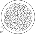
ステップS5までの作業は、前記画像情報の全ての穀粒の画像を集合画像上に配置させるまで繰り返し行う。全ての穀粒の画像の配置後、作成した集合画像を保存及び/又は表示する。図7は作成後の集合画像を示した図である。図8に示すように、集合画像の背景に穀粒鑑定皿26の平面図を用いた画像を作成し保存及び/又は表示してもよい。作成後の集合画像は、コンピュータ2で表示させるだけでなく、インターネットを用いて閲覧可能とすることで、外国など離れた場所であっても穀粒の取引時にその場所で活用することができる。
The operations up to step S5 are repeated until all the grain images of the image information are arranged on the collective image. After the arrangement of all the kernel images, the created collective image is stored and / or displayed. FIG. 7 is a view showing a group image after creation. As shown in FIG. 8, an image using a plan view of the grain appraisal dish 26 may be created, stored, and / or displayed on the background of the collective image. The created aggregated image is not only displayed on the computer 2, but can also be viewed using the Internet, so that it can be used at the time of grain trading even in a remote place such as a foreign country.
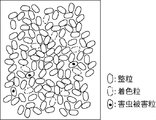
図10は、穀粒の画像同士が重なることなく互いに接した状態の集合画像である。本発明では穀粒の画像同士の重なりの大きさ又は割合の設定値を最小(0又は0%)とすることで、集合画像を容易に作成することができる。
FIG. 10 is a collective image in a state where the images of the grains are in contact with each other without overlapping. In the present invention, an aggregate image can be easily created by setting the setting value of the size or ratio of the overlap between the grain images to a minimum (0 or 0%).
集合画像の作成最終段階において、一粒又は数粒の穀粒の画像を外枠25内に配置できるスペースが確保できない場合は、それら穀粒の画像を無理に配置する必要はなく、その時点での画像を最終的な集合画像とすればよい。
In the final stage of creating the collective image, if there is not enough space to place an image of one or several grains in the outer frame 25, there is no need to forcibly arrange the grains. This image may be the final collective image.
前記隙間αは、任意の色で表示や保存すればよいが、好ましくは穀粒鑑定皿と同一の色にすればよく、青色、黒色又は白色等にすればよい。隙間αは、集合画像におけるバックグランド(背景)となるので、検査する穀粒毎に、検査しやすい色を自由に選択すればよい。
The gap α may be displayed and stored in an arbitrary color, but preferably the same color as the grain identification dish, such as blue, black, or white. Since the gap α is a background in the collective image, a color that can be easily inspected may be freely selected for each grain to be inspected.
上記実施例では、着色粒同士、害虫被害粒同士又は着色粒と害虫被害粒とが接触して配置しないように設定しているが、ステップS1及びステップS4を省略して、着色粒同士、害虫被害粒同士又は着色粒と害虫被害粒とが接触する場合もあり得る集合画像を作成してもよい。
In the above embodiment, the color particles, the pest damage particles, or the color particles and the pest damage particles are set so as not to contact each other, but step S1 and step S4 are omitted, and the color particles, the pests are omitted. A collective image may be created in which damaged grains or colored grains and pest-damaged grains may contact each other.
穀粒の画像を粒単位で取得できるのであれば、本発明の撮像装置として使用することが可能であり、例えば、特開2006-200945号公報に記載されているような、一粒ずつ穀粒を搬送して撮像する装置でも本発明は実施可能である。
If an image of a grain can be obtained in units of grains, it can be used as an imaging device of the present invention. For example, as described in JP-A-2006-200955, each grain The present invention can also be implemented in an apparatus that conveys and images the image.