WO2014002252A1 - 溶鋼の供給開始方法 - Google Patents
溶鋼の供給開始方法 Download PDFInfo
- Publication number
- WO2014002252A1 WO2014002252A1 PCT/JP2012/066688 JP2012066688W WO2014002252A1 WO 2014002252 A1 WO2014002252 A1 WO 2014002252A1 JP 2012066688 W JP2012066688 W JP 2012066688W WO 2014002252 A1 WO2014002252 A1 WO 2014002252A1
- Authority
- WO
- WIPO (PCT)
- Prior art keywords
- nozzle
- molten steel
- long nozzle
- long
- sliding
- Prior art date
- Legal status (The legal status is an assumption and is not a legal conclusion. Google has not performed a legal analysis and makes no representation as to the accuracy of the status listed.)
- Ceased
Links
Images

Classifications
-
- B—PERFORMING OPERATIONS; TRANSPORTING
- B22—CASTING; POWDER METALLURGY
- B22D—CASTING OF METALS; CASTING OF OTHER SUBSTANCES BY THE SAME PROCESSES OR DEVICES
- B22D41/00—Casting melt-holding vessels, e.g. ladles, tundishes, cups or the like
- B22D41/14—Closures
- B22D41/44—Consumable closure means, i.e. closure means being used only once
-
- B—PERFORMING OPERATIONS; TRANSPORTING
- B22—CASTING; POWDER METALLURGY
- B22D—CASTING OF METALS; CASTING OF OTHER SUBSTANCES BY THE SAME PROCESSES OR DEVICES
- B22D11/00—Continuous casting of metals, i.e. casting in indefinite lengths
- B22D11/10—Supplying or treating molten metal
-
- B—PERFORMING OPERATIONS; TRANSPORTING
- B22—CASTING; POWDER METALLURGY
- B22D—CASTING OF METALS; CASTING OF OTHER SUBSTANCES BY THE SAME PROCESSES OR DEVICES
- B22D41/00—Casting melt-holding vessels, e.g. ladles, tundishes, cups or the like
- B22D41/14—Closures
- B22D41/44—Consumable closure means, i.e. closure means being used only once
- B22D41/46—Refractory plugging masses
- B22D41/465—Unplugging a vessel discharge port
Definitions
- the present invention relates to a method for starting the supply of molten steel from a ladle to a tundish in a continuous casting operation, and in particular, a method for starting the supply of molten steel with the lower end of a long nozzle immersed in the molten steel in the tundish.
- a method for starting the supply of molten steel with the lower end of a long nozzle immersed in the molten steel in the tundish is about.
- the molten steel decarburized in the smelting furnace is put into a ladle and subjected to secondary refining and the like in the ladle.
- the molten steel after the refining is placed on the turret of the continuous casting machine together with the ladle and set above the tundish.
- a sliding nozzle is installed immediately below the upper nozzle that discharges molten steel in the ladle, and a long nozzle is attached to the lower part (lower nozzle) of the sliding nozzle via a support device.
- the long nozzle is set to the sliding nozzle so as not to cause a gap between the lower portion of the sliding nozzle and the long nozzle.
- molten steel is supplied from the ladle to the tundish through the long nozzle to perform pouring.
- Molten steel pouring is performed without immersing the lower end (front end) of the long nozzle in the molten steel in the tundish, and so-called open pouring and immersion pouring in which the lower end of the long nozzle is immersed in the molten steel are performed. It has been broken. However, in the case of open pouring, entrainment of slag formed on the surface of the molten steel in the tundish may occur, and the cleanliness of the molten steel may be impaired by slag or oxide (inclusions).
- immersion pouring that can suppress slag entrainment is mainly performed, and in particular, when many heats are continuously cast, slag and oxide (inclusions) in the slab joints This has the advantage that contamination of the molten steel due to etc. can be prevented.
- the molten steel in the ladle may cool and solidify and nozzle clogging may occur. Therefore, before pouring the molten steel into the ladle, (Hereinafter also referred to as “packed sand”) is prefilled in the upper nozzle to prevent the molten steel from entering the discharge hole (nozzle hole).
- packed sand is prefilled in the upper nozzle to prevent the molten steel from entering the discharge hole (nozzle hole).
- the packed sand falls into the inner hole of the long nozzle and accumulates on the molten steel surface. For this reason, it is necessary to pour the molten steel into the tundish after the accumulated packed sand is quickly discharged out of the long nozzle by the falling flow of the molten steel. In the case where the deposited sand that has fallen and deposited cannot be discharged satisfactorily, clogged sand remains in the inner hole of the long nozzle.
- the molten steel spouts out from the joint between the sliding nozzle and the long nozzle (molten steel leaks), and the nitrogen concentration in the molten steel rises due to the air flowing into the inner hole of the long nozzle from the gap generated in the joint (hereinafter referred to as “Nitrogen Pickup”) Also called).
- the molten steel surface is solidified (hereinafter also referred to as “skinning”) at the inner hole of the long nozzle when the ladle is replaced, and the inner hole of the long nozzle is blocked. It may occur.
- casting is started by setting the inner diameter of the lower end part immersed in the molten steel in the tundish to be 1.5 times or more and less than 2.25 times than the inner diameter of the straight body part above the long nozzle.
- an invention is disclosed in which the fallen accumulated sand is reduced in thickness so that it can be easily discharged out of the long nozzle and does not block the inner hole of the long nozzle.
- the blowing port of the inert gas into a nozzle is provided in the predetermined position of the ladle nozzle (lower nozzle) or the long nozzle, and the lower end part of the long nozzle was immersed under the molten steel surface in the tundish.
- a method is disclosed in which the ladle nozzle and the long nozzle are opened while the inert gas is blown before the ladle nozzle is opened.
- Patent Document 3 when waiting for the next ladle to be installed while the lower end of the long nozzle is immersed and held in the molten steel in the tundish, combustion heat generated by contact with the molten steel in the long nozzle or by its radiant heat A method is disclosed in which a substance is put into an inner hole of a long nozzle, a next ladle is attached to the long nozzle, and molten steel injection from the next ladle is started.
- Japanese Unexamined Patent Publication No. 2002-001496 Japanese Unexamined Patent Publication No. 59-125250 Japanese Unexamined Patent Publication No. 63-137553
- Patent Document 1 has a certain effect in preventing the long nozzle from being blocked, but there are still cases in which the long nozzle is blocked by the clogged sand that has fallen and accumulated.
- As a method of reliably discharging the accumulated sand that has fallen out of the long nozzle it is conceivable to set the dimension of the expanded diameter of the long nozzle to a very large value. There is a risk that the expanded diameter portion of the nozzle vibrates, and molten steel leaks from the connecting portion between the sliding nozzle and the long nozzle, or the neck (upper end) of the long nozzle breaks.
- Patent Document 2 cannot prevent the occurrence of skinning when replacing the ladle.
- skinning occurs, the molten steel solidified by the inert gas cannot be removed, and obstruction of the long nozzle is inevitable.
- inert gas tends to leak and it is difficult to control the internal pressure of the long nozzle.
- Patent Document 3 has a certain effect in preventing the skinning when replacing the ladle.
- the technique described in Patent Document 3 has a certain effect in preventing the skinning when replacing the ladle.
- the immersion depth of the long nozzle is large, the stuffed sand is contained in the long nozzle.
- the stuffed sand is contained in the long nozzle.
- it cannot drop and accumulate on the surface of the molten steel.
- solidified molten steel adheres and remains on the inner wall surface of the long nozzle. There is also.
- the present invention has been made in view of the above circumstances, and provides a molten steel supply start method capable of reliably preventing a long nozzle blockage in immersion pouring and preventing a trouble at the start of molten steel supply.
- the purpose is to provide.
- the inventors of the present invention have the following factors inducing the clogging of the long nozzle: solidified molten steel that clogs the inner hole of the long nozzle in the form of a plug when the ladle is replaced, and packed sand that has fallen and accumulated on the surface of the molten steel in the long nozzle.
- the knowledge that it is the frictional force which acts on is obtained.
- the molten steel surface in the long nozzle is prevented from solidifying, and the friction force acting on the clogged sand falling on the molten steel surface in the long nozzle is minimized to block the long nozzle. To prevent.
- a charging step in which an exothermic gasification substance is charged into the long nozzle from an opening at the upper end of the long nozzle dipped in molten steel in the tundish; Thereafter, the upper end portion of the long nozzle is connected to a sliding nozzle that is connected to a discharge hole in the bottom surface of the ladle and controls the flow rate of the molten steel flowing down from the ladle through a sealing material.
- a dropping step of dropping into the long nozzle through a nozzle; and a immersion depth of the lower end portion of the long nozzle in the charging step with respect to the molten steel surface L is 50 ⁇ 350mm.
- the exothermic gasification substance may be an organic substance.
- the input amount of the exothermic gasification substance in the charging step may be 20 to 400 g.
- a lower nozzle is connected directly below the sliding nozzle, and the upper end portion of the long nozzle is connected to the lower nozzle with the seal. You may connect through a material.
- the exothermic gasifying substance is added before the long nozzle is connected to the sliding nozzle of the ladle. Insert into the inner hole of the long nozzle.
- the temperature of the molten steel surface in the long nozzle is prevented from lowering due to the heat generation of the exothermic gasification substance and the molten steel stirring effect due to gas generation, and solidification (skinning) of the molten steel surface in the long nozzle is prevented.
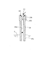
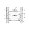
- FIG. 6 shows the force acting on the packed sand 19 falling and deposited on the molten steel surface in the long nozzle 10.
- the gravity and buoyancy acting on the packed sand 19 are ignored in the following description.
- the packing sand 19 is composed of a granular material, so that the force in the vertical direction remains as it is. Instead of being transmitted downward, a component force toward the side is generated.
- the molten steel static pressure 25 is dispersed as it falls from the top of the packed sand 19 to the lower portion of the packed sand 19, the downward stress 26 directed downward is reduced, and the lateral stress 27 pressing the inner wall of the long nozzle 10 is increased.
- the side stress 27 increases, the frictional force 28 acting between the packed sand 19 and the inner wall surface of the long nozzle 10 increases, so that it may be difficult to discharge the packed sand 19 by the molten steel static pressure 25. is there.
- the side stress 27 As the packed sand 19 descends in the long nozzle 10, the side stress 27 further increases and the frictional force 28 increases, making it more difficult to discharge the packed sand 19.
- the immersion depth L of the long nozzle at the start of pouring is set to 50 to 350 mm, and the internal pressure of the long nozzle is increased by using the gas generated from the above-described exothermic gasification substance.
- the molten steel surface was lowered to the lower end of the long nozzle. The clogged sand that falls and accumulates on the molten steel surface lowered in advance in the long nozzle is easily discharged out of the long nozzle by the pressure of the molten steel that subsequently falls.
- the immersion depth L of the lower end of the long nozzle is less than 50 mm (particularly less than 40 mm)
- the slag of the molten steel surface of the tundish is caught in the entrained flow induced by the molten steel discharged from the lower end of the long nozzle. This is not preferable because the quality of the molten steel deteriorates.
- the immersion depth L of the lower end of the long nozzle exceeds 350 mm, the frictional force acting on the packed sand falling on the molten steel surface in the long nozzle becomes too large, and the accumulated packed sand is removed from the long nozzle.
- the internal pressure of the long nozzle can be controlled by the immersion depth and the amount of exothermic gasification substance introduced.
- the gas generated from the exothermic gasification substance may leak from the connecting part between the lower part of the sliding nozzle (or the lower nozzle below it) and the long nozzle, it may be difficult to control the internal pressure. It is necessary to interpose a sealing material.
- the internal pressure of the long nozzle having an immersion depth of Lmm exceeds the value at which bubbles can be confirmed from the molten steel surface of the tundish for the following reason.
- the internal pressure of a long nozzle having an immersion depth of Lmm, in which bubbles can be confirmed from the molten steel surface of the tundish is referred to as an Lmm iron pillar.
- the internal pressure of the long nozzle is approximately the same as that of the Lmm iron column, that is, the internal pressure of the long nozzle is approximately the same as that of the iron column (molten steel column) having a height of Lmm, the molten steel surface in the long nozzle is at the lower end (tip) of the long nozzle. Go down.
- the gas in the long nozzle is released to the outside of the long nozzle and can be observed as bubbles on the molten steel surface in the tundish.
- the molten steel surface in the long nozzle is located at the lower end of the long nozzle, and it is possible to reliably discharge clogged sand.
- air bubbles cannot be confirmed, when the packed sand cannot be discharged, or when gas leaks at the long nozzle connecting part interposing the sealing material (a gas leakage path is generated and directly connected to the molten steel nitrogen pickup). Can be considered.
- the molten steel supply start method according to the present invention, solidification of the molten steel surface in the long nozzle at the time of ladle replacement is prevented.
- the frictional force acting on the sand that has fallen and accumulated on the surface of the molten steel in the long nozzle is minimized, so that the long nozzle is reliably prevented from being blocked during immersion pouring, and troubles at the start of molten steel supply can be prevented. Can be prevented.
- the internal pressure of the long nozzle with the immersion depth Lmm exceeds the Lmm iron pillar, the gas released to the outside of the long nozzle can be observed as bubbles on the surface of the molten steel in the tundish. Thereby, it can confirm visually that the molten steel surface in a long nozzle is located in a long nozzle lower end.
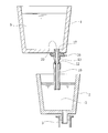
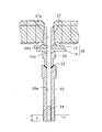
- a method for starting supply of molten steel according to an embodiment of the present invention will be described below with reference to FIGS.
- the long nozzle will be described on the premise that it is erected so that its head is located on the upper side and its tip is located on the lower side.
- the molten steel 5 in the ladle 1 set above the tundish 2 is poured into the tundish 2 from the discharge hole 20 on the bottom surface of the ladle 1 by the long nozzle 10. Further, it is sent into the mold 3 and cast.
- the long nozzle 10 has a cylindrical shape, and a flow path 10a (inner hole) through which the molten steel 5 flows is formed along the central axis.
- a conical recess 10b into which the lower end of the sliding nozzle 16 (or the lower nozzle 13 below) is fitted is formed.
- the sealing material 12 is placed in the conical recess 10b in order to ensure the airtightness between the sliding nozzle 16 (or the lower nozzle 13 below the sliding nozzle 16) and the long nozzle 10 very closely.
- the sealing material 12 those conventionally used such as joint materials such as refractory mortar, ceramic fiber, and fixed joint material can be used.
- the fixed joint material is a thin plate-like refractory processed in advance in a shape close to the shape of the joining portion, and is excellent in releasability and workability.
- the bottom part of the ladle 1, the upper nozzle 17, the sliding nozzle 16, and the lower nozzle 13 are generally connected to each other in a state in which airtightness is secured in advance using a mortar or the like and used for continuous casting operation. Also good.
- the long nozzle 10 often replaces a used product with a new one when used in continuous casting operation, and connection using mortar or the like is inconvenient. Airtightness can be secured by placing the material and connecting the sliding nozzle 16 (or the lower nozzle 13 below the sliding nozzle 16).
- the long nozzle 10 with the sealing material 12 set on the top is erected in a state where the lower end portion 10c (tip portion) is immersed in the molten steel 5 in the tundish 2 (not shown). And the exothermic gasification substance 11 is thrown in into the flow path 10a from the upper end part 10d of the long nozzle 10.
- the exothermic gasification substance 11 is a substance that receives heat of molten steel and oxidizes and heats by the atmosphere (oxygen) in the flow path 10a and at the same time gasifies, and uses, for example, organic substances such as paper and wood, and carbon-containing substances such as coal. can do.
- the input amount of the exothermic gasification substance 11 may be about 20 to 400 g as will be described later.
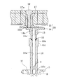
- an upper nozzle 17 for discharging the molten steel 5 in the ladle 1 is attached to the bottom of the ladle 1.
- a sliding nozzle 16 for controlling the flow rate when the molten steel 5 is discharged is provided immediately below the upper nozzle 17.
- the sliding nozzle 16 includes a fixed plate 15 fixed to the bottom of the ladle 1 via a fixed metal frame (not shown), and a sliding plate 14 that slides on the lower surface of the fixed plate 15.
- the lower nozzle 13 is attached to the lower surface of the sliding plate 14.
- the fixed plate 15 has a nozzle hole 15 a (discharge hole 20) communicating with the nozzle hole 17 a (discharge hole 20) of the upper nozzle 17, and the sliding plate 14 communicates with the nozzle hole 13 a of the lower nozzle 13. Nozzle holes 14a are respectively formed.
- the nozzle hole 15a of the fixed plate 15 is sealed by the sliding plate 14, and the nozzle hole 17a of the upper nozzle 17 and the nozzle hole 15a of the fixed plate 15 have SiO 2 , al 2 O 3, MgO or the like packed sand 19 (padding) of the particulate as a main component is filled.
- the long nozzle 10 in which the gas G is generated in the flow path 10a is pushed upward by about 100 to 400 mm, and the lower end portion of the sliding nozzle 16 (or the lower nozzle 13 below it) is moved to the long nozzle 10. In the recess 10b. Then, the sliding nozzle 16 (or the lower nozzle 13 below it) and the long nozzle 10 are connected via the sealing material 12, and the immersion depth L of the lower end portion 10c of the long nozzle 10 after the connection is 50 to 350 mm. .
- the molten steel surface 21 in the long nozzle 10 is relatively lowered with respect to the long nozzle 10, but the effect of the exothermic gasification substance 11 that has been introduced can prevent the molten steel temperature from being lowered.
- the amount of the molten steel 5 adhering to the inner wall of the flow path 10a is reduced, and it is difficult to obstruct the discharge of the packed sand 19 that drops and accumulates when the sliding nozzle 16 is opened.
- the gas G generated by the exothermic gasification substance 11 is contained in the flow path 10a, and the pressure in the flow path 10a (the internal pressure of the long nozzle 10) rises to a value exceeding the Lmm iron pillar.
- the gas G in the flow channel 10 a is released to the outside of the long nozzle 10 and can be observed as bubbles B on the molten steel surface 21 in the tundish 2.
- the situation exceeding the Lmm iron pillar can be realized by adjusting the input amount of the exothermic gasification substance 11, the amount of the exothermic gasification substance 11 introduced into the long nozzle 10 based on the test of the actual machine and the calculation result of the gas generation amount. May be determined in advance.
- a hydraulic cylinder (not shown) that is a driving mechanism connected to the sliding plate 14 is driven to slide the sliding plate 14 in the horizontal direction.
- the nozzle hole 14a of the sliding plate 14 and the nozzle hole 15a of the fixed plate 15 are communicated with each other.
- the filling sand 19 filled in the nozzle hole 17a of the upper nozzle 17 and the nozzle hole 15a of the fixed plate 15 naturally falls in the flow path 10a of the long nozzle 10, and the molten steel located at the lower end of the long nozzle 10 Deposit on the surface 21 (see FIG. 5).
- the packed sand 19 dropped and deposited on the molten steel surface 21 is easily discharged out of the long nozzle 10 by the pressure of the molten steel 5 subsequently falling.
- the present inventors have used cellulose (paper) as an organic substance and a carbon lump capable of gasifying almost 100% by mass (gasification due to lack of oxygen).
- cellulose paper
- the exothermic gasification substance 11 is used as the exothermic gasification substance 11
- the internal pressure of the long nozzle 10 exceeds the Lmm iron pillar. It has been confirmed that there is no significant splash around the long nozzle 10.
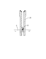
- FIG. 7 shows an example of the correlation between the weight of the paper tube (paper formed into a tubular shape) introduced into the inner hole of the long nozzle 10 as the exothermic gasification substance 11 and the amount of gas generated.
- the space volume of the inner hole of the long nozzle 10 during the test was about 0.02 m 3
- the immersion depth was about 300 mm
- the paper tube burning rate was 40% (calculated from the internal pressure of the long nozzle 10).
- the internal pressure of the long nozzle 10 is less than 14.7 kPa, bubbles B are not generated from the lower end of the long nozzle 10.
- the internal pressure of the long nozzle 10 exceeds 58.8 kPa, Splash has occurred abnormally.
- the internal pressure of the long nozzle 10 is preferably 14.7 kPa to 58.8 kPa.
- an embodiment of the present invention is as follows (1) to (5).
- a charging step in which the exothermic gasification substance 11 is introduced into the long nozzle 10 from the opening of the upper end portion 10d of the long nozzle 10 in which the lower end portion 10c is immersed in the molten steel 5 in the tundish 2; Thereafter, the upper end portion 10 d of the long nozzle 10 is sealed against a sliding nozzle 16 that is in communication with a discharge hole 20 on the bottom surface of the ladle 1 and controls the flow rate of the molten steel 5 flowing down from the ladle 1.
- immersion depth L relative to the molten steel surface 21 is supply start process of the molten steel 5 is 50 ⁇ 350 mm.
- the exothermic gasification substance 11 may be an organic substance.
- the input amount of the exothermic gasification substance 11 in the input step may be 20 to 400 g.
- the lower nozzle 13 is connected directly below the sliding nozzle 16, and the upper end portion 10d of the long nozzle 10 is connected. May be connected to the lower nozzle 13 via the sealing material 12.
- the present invention is not limited to the configuration described in the above-described embodiment, and is within the scope of matters described in the claims.
- Other embodiments and modifications which can be considered in the above are also included.
- the shape of the long nozzle 10 is made into the straight type, the long nozzle 10 which has an enlarged diameter part in a lower end part may be sufficient.
- the lower nozzle 13 was installed between the sliding nozzle 16 and the long nozzle 10, it is good also as a structure which connects the sliding nozzle 16 and the long nozzle 10 directly.
- Table 1 shows a list of test results carried out to verify the effects of the present invention.
- Comparative example 1 was used as a comparison target for the frequency of blockage occurrence in the table and whether or not the actual machine could be used.
- the occurrence frequency of the occlusion it was set as Good when there was an improvement from Comparative Example 1, Fair when it was the same as Comparative Example 1, and Bad when it was worse than Comparative Example 1.
- the actual machine can be used it was set as Good when it was available, Fair when it could be used but inferior to Comparative Example 1, and Bad when it was not.
- the long nozzle 10 was a straight type having an inner diameter of 100 mm and a length of 1.5 m. However, only the comparative example 1 used the long nozzle 10 which expanded the internal diameter of a lower end part 1.4 times.
- Examples 1 to 3 show improvement in the frequency of occurrence of blockage compared to Comparative Example 1, and can be employed in actual machines. However, in the case of Example 3, since the amount of the exothermic gasification substance 11 is too large, splash is abnormally generated around the long nozzle 10, and measures such as a shielding plate for shielding the splash are necessary.
- the comparative example 2 showed improvement in the blockage occurrence frequency as compared with the comparative example 1, since the slag was sometimes caught at the lower end of the long nozzle 10, it was impossible to adopt the actual machine.
- the comparative example 3 was the same as the comparative example 1 in the obstruction
- the comparative example 4 and the comparative example 5 which applied the technique of patent document 3 brought a bad result compared with the comparative example 1 in both the obstruction
- a molten steel supply start method that can reliably prevent a long nozzle from being clogged in immersion pouring and prevent a trouble at the start of the molten steel supply.
Landscapes
- Engineering & Computer Science (AREA)
- Mechanical Engineering (AREA)
- Continuous Casting (AREA)
- Casting Support Devices, Ladles, And Melt Control Thereby (AREA)
- Carbon Steel Or Casting Steel Manufacturing (AREA)
Abstract
Description
特許文献1記載の技術は、ロングノズルの閉塞防止に一定の効果があるが、落下堆積した詰砂によってロングノズルが閉塞するケースが依然として存在する。落下堆積した詰砂をロングノズル外へ確実に排出する方法として、ロングノズル拡径部の寸法を極めて大きな値とすることが考えられるが、そのようにした場合、タンディッシュ内の溶鋼流動によりロングノズルの拡径部が振動して、スライディングノズルとロングノズルの連結部から溶鋼が漏れたり、ロングノズルの首部(上端部)が折損する等のおそれがある。
(1)本発明の一態様は、下端部がタンディッシュ内の溶鋼に浸漬したロングノズルの上端部の開口より、このロングノズル内に発熱ガス化物質を投入する投入工程と;この投入工程の後、前記ロングノズルの前記上端部を、取鍋の底面にある排出孔に連通されてかつ前記取鍋より流下する前記溶鋼の流量制御を行うスライディングノズルに対してシール材を介して連結する連結工程と;この連結工程の後、前記タンディッシュ内の溶鋼湯面における気泡発生を確認するロングノズル内圧確認工程と;このロングノズル内圧確認工程の後、前記排出孔内の詰砂を、前記スライディングノズルを介して前記ロングノズル内に落とし込む落下工程と;を備え、前記投入工程における前記ロングノズルの前記下端部の、前記溶鋼湯面に対する浸漬深さLが50~350mmである。
一般に、ロングノズル10内(円筒状)に充填された粒状の詰砂19の上から溶鋼静圧25を負荷した場合、詰砂19が粒状体から構成されているため、鉛直方向の力はそのまま下方へ伝達されず、側方へ向かう分力が発生する。そのため、詰砂19の頂部から詰砂19の下部に下がるにつれて溶鋼静圧25が分散し、下方に向かう下方応力26が減少し、ロングノズル10の内壁を押圧する側方応力27が増加する。側方応力27が増加すると、詰砂19とロングノズル10の内壁面との間に作用する摩擦力28が大きくなるため、溶鋼静圧25により詰砂19を排出することが困難となる場合がある。詰砂19がロングノズル10内を下降してゆくにつれて、側方応力27が更に増加して摩擦力28が増大し、より詰砂19の排出が困難となる。
なお、以下の説明では、ロングノズルは、その頭部が上側、先端部が下側に位置するように立設されているという前提で説明する。
なお、取鍋1の底部と、上ノズル17と、スライディングノズル16と、下ノズル13とは、一般にモルタル等を用いて予め気密性を確保した状態で互いに連結されて連続鋳造操業に用いられてもよい。ロングノズル10は、連続鋳造操業に用いる際に使用済み品を新品に取り替える場合が多く、モルタル等を用いた連結は不都合があるため、ロングノズル10の上端部10dの円錐状の凹部10bにシール材を載置させて、スライディングノズル16(あるいはその下の下ノズル13)と連結することで気密性が確保できる。
そして、ロングノズル10の上端部10dから流路10a内に発熱ガス化物質11を投入する。
発熱ガス化物質11は、溶鋼熱を受けて流路10a内の大気(酸素)によって酸化発熱すると同時にガス化する物質であり、例えば、紙、木等の有機物、石炭等の炭素含有物を使用することができる。発熱ガス化物質11の投入量は、後述するように、20~400g程度で良い。
スライディングノズル16は、固定金枠(図示省略)を介して取鍋1の底部に固定されている固定プレート15と、固定プレート15の下面に対して摺動する摺動プレート14とを備えており、摺動プレート14の下面には下ノズル13が取り付けられている。また、固定プレート15には、上ノズル17のノズル孔17a(排出孔20)に連通するノズル孔15a(排出孔20)が、摺動プレート14には、下ノズル13のノズル孔13aに連通するノズル孔14aがそれぞれ形成されている。
ロングノズル10の押し上げ時にロングノズル10内の溶鋼湯面21は、ロングノズル10に対して相対的に下がるが、投入した発熱ガス化物質11の効果で溶鋼温度の低下が防止できているため、流路10aの内壁に付着する溶鋼5の量が減少し、スライディングノズル16の開孔時に落下堆積する詰砂19排出の障害になりにくい。
なお、発熱ガス化物質11の投入量調整によりLmm鉄柱を超える状況を実現できるため、実機のテストやガス発生量の試算結果に基づいて、ロングノズル10内に投入する発熱ガス化物質11の量を予め決定しておくと良い。但し、ロングノズル10の内圧がLmm鉄柱を大きく超えることは実現し難い(浸漬深さLで決定される。)が、ガス発生量が極端に多すぎるとロングノズル10の周囲でスプラッシュが発生するため好ましくない。
本試験では、ロングノズル10の内圧が14.7kPa未満だと、ロングノズル10の下端から気泡Bが発生せず、逆にロングノズル10の内圧が58.8kPaを超えると、ロングノズル10周辺においてスプラッシュが異常発生した。従って、ロングノズル10の内圧としては、14.7kPa以上58.8kPa以下が好ましい。
(1)下端部10cがタンディッシュ2内の溶鋼5に浸漬したロングノズル10の上端部10dの開口より、このロングノズル10内に発熱ガス化物質11を投入する投入工程と;この投入工程の後、前記ロングノズル10の前記上端部10dを、取鍋1の底面にある排出孔20に連通されてかつ前記取鍋1より流下する前記溶鋼5の流量制御を行うスライディングノズル16に対してシール材12を介して連結する連結工程と;この連結工程の後、前記タンディッシュ2内の溶鋼湯面21における気泡B発生を確認するロングノズル10内圧確認工程と;このロングノズル10内圧確認工程の後、前記排出孔20内の詰砂19を、前記スライディングノズル16を介して前記ロングノズル10内に落とし込む落下工程と;を備え、前記投入工程における前記ロングノズル10の前記下端部10cの、前記溶鋼湯面21に対する浸漬深さLが50~350mmである溶鋼5の供給開始方法である。
ロングノズル10には、内径100mm、長さ1.5mのストレートタイプを使用した。但し、比較例1のみ、下端部の内径を1.4倍に拡径したロングノズル10を使用した。

比較例4と特許文献3記載の技術を適用した比較例5は、閉塞発生頻度と実機採用可否の双方において比較例1と比べて悪い結果となった。特に、比較例4の場合、試験後の調査において皮張りが確認されると共に、ガス供給孔が閉塞し、周囲で亀裂が発生していた。
また、比較例5は、ロングノズル10の内圧が低いため、溶鋼湯面21上に落下堆積した詰砂19をロングノズル10外へ排出できなかったものと推察される。
2:タンディッシュ
3:鋳型
5:溶鋼
10:ロングノズル
10a:流路(内孔)
10b:凹部
10c:下端部
10d:上端部
11:発熱ガス化物質
12:シール材
13:下ノズル
14:摺動プレート
15:固定プレート
16:スライディングノズル
17:上ノズル
13a、14a、15a、17a:ノズル孔
19:詰砂(詰め物)
20:排出孔
21:溶鋼湯面
25:溶鋼静圧
26:下方応力
27:側方応力
28:摩擦力
B:気泡
G:ガス
L:浸漬深さ
Claims (5)
- 下端部がタンディッシュ内の溶鋼に浸漬したロングノズルの上端部の開口より、このロングノズル内に発熱ガス化物質を投入する投入工程と;
この投入工程の後、前記ロングノズルの前記上端部を、取鍋の底面にある排出孔に連通されてかつ前記取鍋より流下する前記溶鋼の流量制御を行うスライディングノズルに対してシール材を介して連結する連結工程と;
この連結工程の後、前記タンディッシュ内の溶鋼湯面における気泡発生を確認するロングノズル内圧確認工程と;
このロングノズル内圧確認工程の後、前記排出孔内の詰砂を、前記スライディングノズルを介して前記ロングノズル内に落とし込む落下工程と;
を備え、
前記投入工程における前記ロングノズルの前記下端部の、前記溶鋼湯面に対する浸漬深さLが50~350mmである
ことを特徴とする溶鋼の供給開始方法。 - 前記発熱ガス化物質が、有機物であることを特徴とする請求項1に記載の溶鋼の供給開始方法。
- 前記投入工程における前記発熱ガス化物質の投入量が、20~400gであることを特徴とする請求項1又は2に記載の溶鋼の供給開始方法。
- 前記連結工程では、前記スライディングノズルの直下に下ノズルを連結し、前記ロングノズルの前記上端部を、前記下ノズル対して前記シール材を介して連結することを特徴とする請求項1又は2に記載の溶鋼の供給開始方法。
- 前記連結工程では、前記スライディングノズルの直下に下ノズルを連結し、前記ロングノズルの前記上端部を、前記下ノズル対して前記シール材を介して連結することを特徴とする請求項3に記載の溶鋼の供給開始方法。
Priority Applications (4)
| Application Number | Priority Date | Filing Date | Title |
|---|---|---|---|
| CN201280030441.5A CN103648685B (zh) | 2012-06-29 | 2012-06-29 | 钢水的开始供给方法 |
| JP2012544787A JP5170353B1 (ja) | 2012-06-29 | 2012-06-29 | 溶鋼の供給開始方法 |
| PCT/JP2012/066688 WO2014002252A1 (ja) | 2012-06-29 | 2012-06-29 | 溶鋼の供給開始方法 |
| BR112013033005-8A BR112013033005B1 (pt) | 2012-06-29 | 2012-06-29 | Método de iniciação de suprimento de aço fundido |
Applications Claiming Priority (1)
| Application Number | Priority Date | Filing Date | Title |
|---|---|---|---|
| PCT/JP2012/066688 WO2014002252A1 (ja) | 2012-06-29 | 2012-06-29 | 溶鋼の供給開始方法 |
Publications (1)
| Publication Number | Publication Date |
|---|---|
| WO2014002252A1 true WO2014002252A1 (ja) | 2014-01-03 |
Family
ID=48134672
Family Applications (1)
| Application Number | Title | Priority Date | Filing Date |
|---|---|---|---|
| PCT/JP2012/066688 Ceased WO2014002252A1 (ja) | 2012-06-29 | 2012-06-29 | 溶鋼の供給開始方法 |
Country Status (4)
| Country | Link |
|---|---|
| JP (1) | JP5170353B1 (ja) |
| CN (1) | CN103648685B (ja) |
| BR (1) | BR112013033005B1 (ja) |
| WO (1) | WO2014002252A1 (ja) |
Cited By (1)
| Publication number | Priority date | Publication date | Assignee | Title |
|---|---|---|---|---|
| JP2020185593A (ja) * | 2019-05-15 | 2020-11-19 | Jfeスチール株式会社 | 鋼の連続鋳造方法 |
Families Citing this family (2)
| Publication number | Priority date | Publication date | Assignee | Title |
|---|---|---|---|---|
| CN104759612A (zh) * | 2015-04-09 | 2015-07-08 | 马钢(集团)控股有限公司 | 长水口插入式开浇装置及方法 |
| CN108213401B (zh) * | 2018-01-18 | 2020-01-31 | 华北理工大学 | 保护浇注用的冶金水口及保护浇注的方法 |
Citations (3)
| Publication number | Priority date | Publication date | Assignee | Title |
|---|---|---|---|---|
| JPS59125250A (ja) * | 1983-01-07 | 1984-07-19 | Kawasaki Steel Corp | 取鍋ノズルの開孔方法 |
| JPS63137553A (ja) * | 1986-11-27 | 1988-06-09 | Kawasaki Steel Corp | ロングノズル浸漬スタ−ト方法 |
| JPH01133664A (ja) * | 1987-11-20 | 1989-05-25 | Nkk Corp | 取鍋注出ノズルの自然開口法 |
Family Cites Families (2)
| Publication number | Priority date | Publication date | Assignee | Title |
|---|---|---|---|---|
| JPH03243256A (ja) * | 1990-02-19 | 1991-10-30 | Kawasaki Steel Corp | ロングノズルを用いる連続連続鋳造方法 |
| JP4364406B2 (ja) * | 2000-06-20 | 2009-11-18 | 新日本製鐵株式会社 | 連続鋳造用ロングノズル |
-
2012
- 2012-06-29 JP JP2012544787A patent/JP5170353B1/ja active Active
- 2012-06-29 CN CN201280030441.5A patent/CN103648685B/zh active Active
- 2012-06-29 BR BR112013033005-8A patent/BR112013033005B1/pt active IP Right Grant
- 2012-06-29 WO PCT/JP2012/066688 patent/WO2014002252A1/ja not_active Ceased
Patent Citations (3)
| Publication number | Priority date | Publication date | Assignee | Title |
|---|---|---|---|---|
| JPS59125250A (ja) * | 1983-01-07 | 1984-07-19 | Kawasaki Steel Corp | 取鍋ノズルの開孔方法 |
| JPS63137553A (ja) * | 1986-11-27 | 1988-06-09 | Kawasaki Steel Corp | ロングノズル浸漬スタ−ト方法 |
| JPH01133664A (ja) * | 1987-11-20 | 1989-05-25 | Nkk Corp | 取鍋注出ノズルの自然開口法 |
Cited By (2)
| Publication number | Priority date | Publication date | Assignee | Title |
|---|---|---|---|---|
| JP2020185593A (ja) * | 2019-05-15 | 2020-11-19 | Jfeスチール株式会社 | 鋼の連続鋳造方法 |
| JP7136000B2 (ja) | 2019-05-15 | 2022-09-13 | Jfeスチール株式会社 | 鋼の連続鋳造方法 |
Also Published As
| Publication number | Publication date |
|---|---|
| JPWO2014002252A1 (ja) | 2016-05-30 |
| JP5170353B1 (ja) | 2013-03-27 |
| BR112013033005B1 (pt) | 2022-07-19 |
| CN103648685A (zh) | 2014-03-19 |
| CN103648685B (zh) | 2015-03-18 |
| BR112013033005A2 (pt) | 2017-01-31 |
Similar Documents
| Publication | Publication Date | Title |
|---|---|---|
| TWI602630B (zh) | 製成高純度合金鋼材之方法與系統 | |
| CN102834204B (zh) | 真空供应熔融金属的装置 | |
| JP5170353B1 (ja) | 溶鋼の供給開始方法 | |
| CN101410207B (zh) | 熔融金属运送浇包 | |
| JP2015000404A (ja) | 溶湯充填装置および方法 | |
| KR102585828B1 (ko) | 주조 장치 및 주조 방법 | |
| WO2016084154A1 (ja) | 加圧機能を有する自動注湯装置および自動注湯方法 | |
| CN102794443A (zh) | 用于熔融金属的浇注浇包 | |
| JP5849871B2 (ja) | 取鍋ノズルの酸素洗浄装置及び方法 | |
| JP5781863B2 (ja) | 注湯装置と注湯方法 | |
| JP3188195B2 (ja) | 真空鋳込装置 | |
| JPH0119995B2 (ja) | ||
| JP2019162648A (ja) | 溶湯補給装置及び溶湯補給方法 | |
| KR100943086B1 (ko) | 턴디쉬 막힘 방지 장치 | |
| KR100952746B1 (ko) | 개선된 대기 조괴 방법 | |
| CN114901405A (zh) | 熔融材料处理设备和方法 | |
| US4498661A (en) | Teeming ladle | |
| JP2005211904A (ja) | 金属溶湯供給装置 | |
| JP4422086B2 (ja) | 取鍋開孔方法とそれに用いる充填材 | |
| JPS61117210A (ja) | 浸漬管の耐火ライニング補修方法 | |
| CN1302877C (zh) | 用于从一容器中排放熔融金属的排放装置 | |
| JP6171138B2 (ja) | 溶湯容器内の溶湯流出方法 | |
| JP2017217695A (ja) | 鋼の連続鋳造方法 | |
| JPH11151570A (ja) | 溶融金属注湯用ノズルの開孔方法及び開孔装置 | |
| KR101540745B1 (ko) | 필러 투입 장치 및 이를 이용한 용선 처리 방법 |
Legal Events
| Date | Code | Title | Description |
|---|---|---|---|
| ENP | Entry into the national phase |
Ref document number: 2012544787 Country of ref document: JP Kind code of ref document: A |
|
| 121 | Ep: the epo has been informed by wipo that ep was designated in this application |
Ref document number: 12880228 Country of ref document: EP Kind code of ref document: A1 |
|
| REG | Reference to national code |
Ref country code: BR Ref legal event code: B01A Ref document number: 112013033005 Country of ref document: BR |
|
| NENP | Non-entry into the national phase |
Ref country code: DE |
|
| 122 | Ep: pct application non-entry in european phase |
Ref document number: 12880228 Country of ref document: EP Kind code of ref document: A1 |
|
| ENP | Entry into the national phase |
Ref document number: 112013033005 Country of ref document: BR Kind code of ref document: A2 Effective date: 20131220 |