WO2014002243A1 - 車両用充電システム - Google Patents
車両用充電システム Download PDFInfo
- Publication number
- WO2014002243A1 WO2014002243A1 PCT/JP2012/066643 JP2012066643W WO2014002243A1 WO 2014002243 A1 WO2014002243 A1 WO 2014002243A1 JP 2012066643 W JP2012066643 W JP 2012066643W WO 2014002243 A1 WO2014002243 A1 WO 2014002243A1
- Authority
- WO
- WIPO (PCT)
- Prior art keywords
- vehicle
- charging
- reservation setting
- server
- air conditioner
- Prior art date
- Legal status (The legal status is an assumption and is not a legal conclusion. Google has not performed a legal analysis and makes no representation as to the accuracy of the status listed.)
- Ceased
Links
Images






Classifications
-
- B—PERFORMING OPERATIONS; TRANSPORTING
- B60—VEHICLES IN GENERAL
- B60L—PROPULSION OF ELECTRICALLY-PROPELLED VEHICLES; SUPPLYING ELECTRIC POWER FOR AUXILIARY EQUIPMENT OF ELECTRICALLY-PROPELLED VEHICLES; ELECTRODYNAMIC BRAKE SYSTEMS FOR VEHICLES IN GENERAL; MAGNETIC SUSPENSION OR LEVITATION FOR VEHICLES; MONITORING OPERATING VARIABLES OF ELECTRICALLY-PROPELLED VEHICLES; ELECTRIC SAFETY DEVICES FOR ELECTRICALLY-PROPELLED VEHICLES
- B60L58/00—Methods or circuit arrangements for monitoring or controlling batteries or fuel cells, specially adapted for electric vehicles
- B60L58/30—Methods or circuit arrangements for monitoring or controlling batteries or fuel cells, specially adapted for electric vehicles for monitoring or controlling fuel cells
-
- B—PERFORMING OPERATIONS; TRANSPORTING
- B60—VEHICLES IN GENERAL
- B60L—PROPULSION OF ELECTRICALLY-PROPELLED VEHICLES; SUPPLYING ELECTRIC POWER FOR AUXILIARY EQUIPMENT OF ELECTRICALLY-PROPELLED VEHICLES; ELECTRODYNAMIC BRAKE SYSTEMS FOR VEHICLES IN GENERAL; MAGNETIC SUSPENSION OR LEVITATION FOR VEHICLES; MONITORING OPERATING VARIABLES OF ELECTRICALLY-PROPELLED VEHICLES; ELECTRIC SAFETY DEVICES FOR ELECTRICALLY-PROPELLED VEHICLES
- B60L53/00—Methods of charging batteries, specially adapted for electric vehicles; Charging stations or on-board charging equipment therefor; Exchange of energy storage elements in electric vehicles
- B60L53/10—Methods of charging batteries, specially adapted for electric vehicles; Charging stations or on-board charging equipment therefor; Exchange of energy storage elements in electric vehicles characterised by the energy transfer between the charging station and the vehicle
- B60L53/14—Conductive energy transfer
-
- B—PERFORMING OPERATIONS; TRANSPORTING
- B60—VEHICLES IN GENERAL
- B60L—PROPULSION OF ELECTRICALLY-PROPELLED VEHICLES; SUPPLYING ELECTRIC POWER FOR AUXILIARY EQUIPMENT OF ELECTRICALLY-PROPELLED VEHICLES; ELECTRODYNAMIC BRAKE SYSTEMS FOR VEHICLES IN GENERAL; MAGNETIC SUSPENSION OR LEVITATION FOR VEHICLES; MONITORING OPERATING VARIABLES OF ELECTRICALLY-PROPELLED VEHICLES; ELECTRIC SAFETY DEVICES FOR ELECTRICALLY-PROPELLED VEHICLES
- B60L53/00—Methods of charging batteries, specially adapted for electric vehicles; Charging stations or on-board charging equipment therefor; Exchange of energy storage elements in electric vehicles
- B60L53/30—Constructional details of charging stations
- B60L53/305—Communication interfaces
-
- B—PERFORMING OPERATIONS; TRANSPORTING
- B60—VEHICLES IN GENERAL
- B60L—PROPULSION OF ELECTRICALLY-PROPELLED VEHICLES; SUPPLYING ELECTRIC POWER FOR AUXILIARY EQUIPMENT OF ELECTRICALLY-PROPELLED VEHICLES; ELECTRODYNAMIC BRAKE SYSTEMS FOR VEHICLES IN GENERAL; MAGNETIC SUSPENSION OR LEVITATION FOR VEHICLES; MONITORING OPERATING VARIABLES OF ELECTRICALLY-PROPELLED VEHICLES; ELECTRIC SAFETY DEVICES FOR ELECTRICALLY-PROPELLED VEHICLES
- B60L53/00—Methods of charging batteries, specially adapted for electric vehicles; Charging stations or on-board charging equipment therefor; Exchange of energy storage elements in electric vehicles
- B60L53/30—Constructional details of charging stations
- B60L53/31—Charging columns specially adapted for electric vehicles
-
- B—PERFORMING OPERATIONS; TRANSPORTING
- B60—VEHICLES IN GENERAL
- B60L—PROPULSION OF ELECTRICALLY-PROPELLED VEHICLES; SUPPLYING ELECTRIC POWER FOR AUXILIARY EQUIPMENT OF ELECTRICALLY-PROPELLED VEHICLES; ELECTRODYNAMIC BRAKE SYSTEMS FOR VEHICLES IN GENERAL; MAGNETIC SUSPENSION OR LEVITATION FOR VEHICLES; MONITORING OPERATING VARIABLES OF ELECTRICALLY-PROPELLED VEHICLES; ELECTRIC SAFETY DEVICES FOR ELECTRICALLY-PROPELLED VEHICLES
- B60L53/00—Methods of charging batteries, specially adapted for electric vehicles; Charging stations or on-board charging equipment therefor; Exchange of energy storage elements in electric vehicles
- B60L53/60—Monitoring or controlling charging stations
- B60L53/68—Off-site monitoring or control, e.g. remote control
-
- B—PERFORMING OPERATIONS; TRANSPORTING
- B60—VEHICLES IN GENERAL
- B60L—PROPULSION OF ELECTRICALLY-PROPELLED VEHICLES; SUPPLYING ELECTRIC POWER FOR AUXILIARY EQUIPMENT OF ELECTRICALLY-PROPELLED VEHICLES; ELECTRODYNAMIC BRAKE SYSTEMS FOR VEHICLES IN GENERAL; MAGNETIC SUSPENSION OR LEVITATION FOR VEHICLES; MONITORING OPERATING VARIABLES OF ELECTRICALLY-PROPELLED VEHICLES; ELECTRIC SAFETY DEVICES FOR ELECTRICALLY-PROPELLED VEHICLES
- B60L2200/00—Type of vehicles
- B60L2200/12—Bikes
-
- B—PERFORMING OPERATIONS; TRANSPORTING
- B60—VEHICLES IN GENERAL
- B60L—PROPULSION OF ELECTRICALLY-PROPELLED VEHICLES; SUPPLYING ELECTRIC POWER FOR AUXILIARY EQUIPMENT OF ELECTRICALLY-PROPELLED VEHICLES; ELECTRODYNAMIC BRAKE SYSTEMS FOR VEHICLES IN GENERAL; MAGNETIC SUSPENSION OR LEVITATION FOR VEHICLES; MONITORING OPERATING VARIABLES OF ELECTRICALLY-PROPELLED VEHICLES; ELECTRIC SAFETY DEVICES FOR ELECTRICALLY-PROPELLED VEHICLES
- B60L2240/00—Control parameters of input or output; Target parameters
- B60L2240/70—Interactions with external data bases, e.g. traffic centres
-
- B—PERFORMING OPERATIONS; TRANSPORTING
- B60—VEHICLES IN GENERAL
- B60L—PROPULSION OF ELECTRICALLY-PROPELLED VEHICLES; SUPPLYING ELECTRIC POWER FOR AUXILIARY EQUIPMENT OF ELECTRICALLY-PROPELLED VEHICLES; ELECTRODYNAMIC BRAKE SYSTEMS FOR VEHICLES IN GENERAL; MAGNETIC SUSPENSION OR LEVITATION FOR VEHICLES; MONITORING OPERATING VARIABLES OF ELECTRICALLY-PROPELLED VEHICLES; ELECTRIC SAFETY DEVICES FOR ELECTRICALLY-PROPELLED VEHICLES
- B60L2250/00—Driver interactions
- B60L2250/14—Driver interactions by input of vehicle departure time
-
- B—PERFORMING OPERATIONS; TRANSPORTING
- B60—VEHICLES IN GENERAL
- B60L—PROPULSION OF ELECTRICALLY-PROPELLED VEHICLES; SUPPLYING ELECTRIC POWER FOR AUXILIARY EQUIPMENT OF ELECTRICALLY-PROPELLED VEHICLES; ELECTRODYNAMIC BRAKE SYSTEMS FOR VEHICLES IN GENERAL; MAGNETIC SUSPENSION OR LEVITATION FOR VEHICLES; MONITORING OPERATING VARIABLES OF ELECTRICALLY-PROPELLED VEHICLES; ELECTRIC SAFETY DEVICES FOR ELECTRICALLY-PROPELLED VEHICLES
- B60L2250/00—Driver interactions
- B60L2250/20—Driver interactions by driver identification
-
- Y—GENERAL TAGGING OF NEW TECHNOLOGICAL DEVELOPMENTS; GENERAL TAGGING OF CROSS-SECTIONAL TECHNOLOGIES SPANNING OVER SEVERAL SECTIONS OF THE IPC; TECHNICAL SUBJECTS COVERED BY FORMER USPC CROSS-REFERENCE ART COLLECTIONS [XRACs] AND DIGESTS
- Y02—TECHNOLOGIES OR APPLICATIONS FOR MITIGATION OR ADAPTATION AGAINST CLIMATE CHANGE
- Y02T—CLIMATE CHANGE MITIGATION TECHNOLOGIES RELATED TO TRANSPORTATION
- Y02T10/00—Road transport of goods or passengers
- Y02T10/60—Other road transportation technologies with climate change mitigation effect
- Y02T10/70—Energy storage systems for electromobility, e.g. batteries
-
- Y—GENERAL TAGGING OF NEW TECHNOLOGICAL DEVELOPMENTS; GENERAL TAGGING OF CROSS-SECTIONAL TECHNOLOGIES SPANNING OVER SEVERAL SECTIONS OF THE IPC; TECHNICAL SUBJECTS COVERED BY FORMER USPC CROSS-REFERENCE ART COLLECTIONS [XRACs] AND DIGESTS
- Y02—TECHNOLOGIES OR APPLICATIONS FOR MITIGATION OR ADAPTATION AGAINST CLIMATE CHANGE
- Y02T—CLIMATE CHANGE MITIGATION TECHNOLOGIES RELATED TO TRANSPORTATION
- Y02T10/00—Road transport of goods or passengers
- Y02T10/60—Other road transportation technologies with climate change mitigation effect
- Y02T10/7072—Electromobility specific charging systems or methods for batteries, ultracapacitors, supercapacitors or double-layer capacitors
-
- Y—GENERAL TAGGING OF NEW TECHNOLOGICAL DEVELOPMENTS; GENERAL TAGGING OF CROSS-SECTIONAL TECHNOLOGIES SPANNING OVER SEVERAL SECTIONS OF THE IPC; TECHNICAL SUBJECTS COVERED BY FORMER USPC CROSS-REFERENCE ART COLLECTIONS [XRACs] AND DIGESTS
- Y02—TECHNOLOGIES OR APPLICATIONS FOR MITIGATION OR ADAPTATION AGAINST CLIMATE CHANGE
- Y02T—CLIMATE CHANGE MITIGATION TECHNOLOGIES RELATED TO TRANSPORTATION
- Y02T10/00—Road transport of goods or passengers
- Y02T10/60—Other road transportation technologies with climate change mitigation effect
- Y02T10/72—Electric energy management in electromobility
-
- Y—GENERAL TAGGING OF NEW TECHNOLOGICAL DEVELOPMENTS; GENERAL TAGGING OF CROSS-SECTIONAL TECHNOLOGIES SPANNING OVER SEVERAL SECTIONS OF THE IPC; TECHNICAL SUBJECTS COVERED BY FORMER USPC CROSS-REFERENCE ART COLLECTIONS [XRACs] AND DIGESTS
- Y02—TECHNOLOGIES OR APPLICATIONS FOR MITIGATION OR ADAPTATION AGAINST CLIMATE CHANGE
- Y02T—CLIMATE CHANGE MITIGATION TECHNOLOGIES RELATED TO TRANSPORTATION
- Y02T90/00—Enabling technologies or technologies with a potential or indirect contribution to GHG emissions mitigation
- Y02T90/10—Technologies relating to charging of electric vehicles
- Y02T90/12—Electric charging stations
-
- Y—GENERAL TAGGING OF NEW TECHNOLOGICAL DEVELOPMENTS; GENERAL TAGGING OF CROSS-SECTIONAL TECHNOLOGIES SPANNING OVER SEVERAL SECTIONS OF THE IPC; TECHNICAL SUBJECTS COVERED BY FORMER USPC CROSS-REFERENCE ART COLLECTIONS [XRACs] AND DIGESTS
- Y02—TECHNOLOGIES OR APPLICATIONS FOR MITIGATION OR ADAPTATION AGAINST CLIMATE CHANGE
- Y02T—CLIMATE CHANGE MITIGATION TECHNOLOGIES RELATED TO TRANSPORTATION
- Y02T90/00—Enabling technologies or technologies with a potential or indirect contribution to GHG emissions mitigation
- Y02T90/10—Technologies relating to charging of electric vehicles
- Y02T90/14—Plug-in electric vehicles
-
- Y—GENERAL TAGGING OF NEW TECHNOLOGICAL DEVELOPMENTS; GENERAL TAGGING OF CROSS-SECTIONAL TECHNOLOGIES SPANNING OVER SEVERAL SECTIONS OF THE IPC; TECHNICAL SUBJECTS COVERED BY FORMER USPC CROSS-REFERENCE ART COLLECTIONS [XRACs] AND DIGESTS
- Y02—TECHNOLOGIES OR APPLICATIONS FOR MITIGATION OR ADAPTATION AGAINST CLIMATE CHANGE
- Y02T—CLIMATE CHANGE MITIGATION TECHNOLOGIES RELATED TO TRANSPORTATION
- Y02T90/00—Enabling technologies or technologies with a potential or indirect contribution to GHG emissions mitigation
- Y02T90/10—Technologies relating to charging of electric vehicles
- Y02T90/16—Information or communication technologies improving the operation of electric vehicles
-
- Y—GENERAL TAGGING OF NEW TECHNOLOGICAL DEVELOPMENTS; GENERAL TAGGING OF CROSS-SECTIONAL TECHNOLOGIES SPANNING OVER SEVERAL SECTIONS OF THE IPC; TECHNICAL SUBJECTS COVERED BY FORMER USPC CROSS-REFERENCE ART COLLECTIONS [XRACs] AND DIGESTS
- Y02—TECHNOLOGIES OR APPLICATIONS FOR MITIGATION OR ADAPTATION AGAINST CLIMATE CHANGE
- Y02T—CLIMATE CHANGE MITIGATION TECHNOLOGIES RELATED TO TRANSPORTATION
- Y02T90/00—Enabling technologies or technologies with a potential or indirect contribution to GHG emissions mitigation
- Y02T90/10—Technologies relating to charging of electric vehicles
- Y02T90/16—Information or communication technologies improving the operation of electric vehicles
- Y02T90/167—Systems integrating technologies related to power network operation and communication or information technologies for supporting the interoperability of electric or hybrid vehicles, i.e. smartgrids as interface for battery charging of electric vehicles [EV] or hybrid vehicles [HEV]
-
- Y—GENERAL TAGGING OF NEW TECHNOLOGICAL DEVELOPMENTS; GENERAL TAGGING OF CROSS-SECTIONAL TECHNOLOGIES SPANNING OVER SEVERAL SECTIONS OF THE IPC; TECHNICAL SUBJECTS COVERED BY FORMER USPC CROSS-REFERENCE ART COLLECTIONS [XRACs] AND DIGESTS
- Y02—TECHNOLOGIES OR APPLICATIONS FOR MITIGATION OR ADAPTATION AGAINST CLIMATE CHANGE
- Y02T—CLIMATE CHANGE MITIGATION TECHNOLOGIES RELATED TO TRANSPORTATION
- Y02T90/00—Enabling technologies or technologies with a potential or indirect contribution to GHG emissions mitigation
- Y02T90/40—Application of hydrogen technology to transportation, e.g. using fuel cells
-
- Y—GENERAL TAGGING OF NEW TECHNOLOGICAL DEVELOPMENTS; GENERAL TAGGING OF CROSS-SECTIONAL TECHNOLOGIES SPANNING OVER SEVERAL SECTIONS OF THE IPC; TECHNICAL SUBJECTS COVERED BY FORMER USPC CROSS-REFERENCE ART COLLECTIONS [XRACs] AND DIGESTS
- Y04—INFORMATION OR COMMUNICATION TECHNOLOGIES HAVING AN IMPACT ON OTHER TECHNOLOGY AREAS
- Y04S—SYSTEMS INTEGRATING TECHNOLOGIES RELATED TO POWER NETWORK OPERATION, COMMUNICATION OR INFORMATION TECHNOLOGIES FOR IMPROVING THE ELECTRICAL POWER GENERATION, TRANSMISSION, DISTRIBUTION, MANAGEMENT OR USAGE, i.e. SMART GRIDS
- Y04S30/00—Systems supporting specific end-user applications in the sector of transportation
- Y04S30/10—Systems supporting the interoperability of electric or hybrid vehicles
- Y04S30/12—Remote or cooperative charging
Definitions
- the present invention relates to a charging system in which reservation settings relating to charging timing from an external power source to a power storage device of a vehicle can be changed by a mobile communication terminal via a server.
- US Patent Application Publication No. 2012/0086395 discloses a technique for controlling charging of a vehicle battery (summary).
- the present invention has been made in consideration of such problems, and an object of the present invention is to provide a vehicle charging system capable of improving the convenience of the user regarding the charge reservation.
- a charging system for a vehicle is capable of changing a reservation setting relating to a charging timing from an external power source to a power storage device of a vehicle by a mobile communication terminal via a server, wherein the vehicle performs the reservation setting.
- a first storage unit that stores the reservation setting, and the server includes a second storage unit that stores the reservation setting, and when there is a transmission request for the reservation setting from the mobile communication terminal, the server stores the second storage unit.
- the reservation setting stored in the unit is transmitted to the portable communication terminal, the portable communication terminal displays the received reservation setting, and when the reservation setting is changed in the vehicle, the vehicle sets the server to the server.
- the changed reservation setting is transmitted to the second storage unit, the changed reservation setting is stored in the second storage unit, and the reservation setting stored in each of the first storage unit and the second storage unit is stored. Characterized in that to synchronize.
- the user can check the reservation setting stored in the server with the mobile communication terminal. Therefore, the reservation setting can be confirmed without waiting for communication between the server and the vehicle, and the waiting time can be shortened to improve the convenience for the user.
- the reservation settings stored in the server are synchronized with those stored in the vehicle at that time. For this reason, when there is a request from the mobile communication terminal, the reservation setting stored in the server is the latest. Therefore, the user can confirm an accurate reservation setting, and the convenience of the user can be improved from this point.
- the charging system includes a remote controller that commands immediate start or immediate end of charging from the external power source to the power storage device and is separate from the mobile communication terminal, and the reservation setting is changed in the vehicle When the vehicle and the server cannot communicate with each other, the changed reservation setting may be transmitted from the vehicle to the server when the remote controller is operated.
- the remote controller transmits the changed reservation setting from the vehicle to the server when an immediate start or immediate end of charging of the power storage device is commanded. Therefore, for example, if it is configured to transmit information associated with the operation of the remote controller (for example, start or end of charging) together with the reservation setting after the change, it is possible to reduce the number of times of communication between the vehicle and the server. Become.
- the second storage unit stores information on whether or not the power storage device is charging together with the reservation setting and the vehicle state
- the server transmits the vehicle state information stored in the second storage unit to the mobile communication terminal
- the mobile communication terminal displays the received vehicle state information, and when the reservation setting is changed in the vehicle and the vehicle and the server cannot communicate, the remote controller can immediately start the charging.
- the vehicle state information including the changed reservation setting may be transmitted from the vehicle to the server, triggered by the command.
- the changed reservation setting is transmitted from the vehicle to the server. Therefore, for example, if the configuration is such that the information (for example, start of charging) accompanying the operation of the remote controller is transmitted together with the changed reservation setting, the number of communications between the vehicle and the server can be reduced. Further, when requested from the mobile communication terminal, the user can confirm whether or not charging is in progress and the reservation setting only by communication between the mobile communication terminal and the server. Therefore, the user can confirm the start of charging and accurate reservation setting in a short time, and the convenience of the user can be improved.
- the remote controller may further command start or stop of the air conditioner of the vehicle.
- the reservation setting is retransmitted when the remote controller is operated
- the remote controller is instructed to immediately start or stop charging of the power storage device or to start or stop the air conditioner
- the changed reservation setting is transmitted from the vehicle to the server. Therefore, for example, if it is configured to transmit information associated with the operation of the remote controller (for example, start or end of charging or start or stop of the air conditioner) together with the reservation setting after the change, between the vehicle and the server It is possible to reduce the number of communications.
- the remote controller commands the immediate start of charging from the external power source to the power storage device
- the external power source is triggered when the remote controller is operated even when the reservation setting exists in the vehicle.
- To start charging the power storage device immediately and maintain the reservation setting in the vehicle.
- the reservation setting is maintained. Therefore, it is possible to save the user from having to reset the reservation timing, and from this point, the convenience of the user can be improved.
- the charging system is capable of changing a reservation setting relating to charging timing from an external power source to a power storage device of a vehicle by a mobile communication terminal via a server, and the vehicle stores the reservation setting.
- a first storage unit, and the server includes a second storage unit that stores the reservation setting.
- the server stores the reservation setting in the second storage unit.
- the stored reservation setting is transmitted to the mobile communication terminal, and the mobile communication terminal displays the received reservation setting.
- the user can check the reservation setting stored in the server with the mobile communication terminal. Therefore, the reservation setting can be confirmed without waiting for communication between the server and the vehicle, and the waiting time can be shortened to improve the convenience for the user.
- FIG. 1 is a block configuration diagram of a vehicle power supply system (hereinafter also referred to as “power supply system”) as a vehicle charging system according to an embodiment of the present invention. It is a block diagram of each component of the power supply system. It is a front view of the remote controller of the vehicle in the said electric power supply system. In the said embodiment, it is a figure which shows an example of the screen used when the operation
- FIG. 1 is a block configuration diagram of a vehicle power supply system 10 (hereinafter also referred to as “power supply system 10” or “system 10”) as a vehicle charging system according to an embodiment of the present invention.
- FIG. 2 is a block diagram of each component of the system 10.
- the system 10 includes a vehicle 12, an external charging device 14, a remote controller 16, a mobile communication terminal 18, and a server 20. 1 and 2 show a configuration in which the system 10 has one component, but the system 10 has a plurality of components (for example, one server 20 and a plurality of components).
- the vehicle 12, the external charging device 14, the remote controller 16, and the portable communication terminal 18 are associated with each other.
- the power from the external charging device 14 is used for charging the battery 30 (FIG. 2) and operating the air conditioner 32.
- the charging of the battery 30 and the operation of the air conditioner 32 can be controlled by a user operation on the steering switch 34, the remote controller 16, or the portable communication terminal 18 of the vehicle 12.
- the mobile communication terminal 18 When an operation is performed via the mobile communication terminal 18, communication between the vehicle 12 and the mobile communication terminal 18 is performed via the server 20.
- air conditioner may be abbreviated as “air conditioner” and “remote controller” may be abbreviated as “remote controller”.
- the vehicle 12 is a narrowly-defined electric vehicle that has only a travel motor (not shown) as a drive source and supplies power to the travel motor only from the battery 30 (power storage device).
- the vehicle 12 may be an electric vehicle such as a plug-in hybrid vehicle or a fuel cell vehicle.
- the traveling motor is driven by the electric power from the battery 30 and the air conditioner 32 is operated in accordance with a user operation.
- the battery 30 can be selectively charged and the air conditioner 32 can be selectively operated by the electric power from the external charging device 14.
- the charging of the battery 30 and the operation of the air conditioner 32 are switched and not performed at the same time (however, as will be described later, both can be performed simultaneously) .
- the vehicle 12 in addition to the battery 30, the air conditioner 32, and the steering switch 34, the vehicle 12 includes a battery electronic control device 36 (hereinafter referred to as “battery ECU 36”), a navigation device 38, and an air conditioner electronic control device. 40 (hereinafter referred to as “air conditioner ECU 40”), temperature sensor 42, meter 44, meter electronic control unit 46 (hereinafter referred to as “meter ECU 46”), and bidirectional remote control unit 48 ⁇ hereinafter referred to as “BRU 48” (BRU: Bidirectional Remote-control Communication Unit).
- BRU 48 bidirectional remote control unit 48
- the first antenna 50, and the telematics control unit 52 ⁇ hereinafter referred to as "TCU52" (TCU: Telematics Control Unit).
- Each of the ECUs 36, 40, 46, BRU 48, and TCU 52 includes an input / output unit, a calculation unit, and a storage unit.
- the meter 44 indicates the vehicle speed, the remaining capacity (SOC: StateSOof Charge) of the battery 30, and the like.
- the battery 30 is mainly a power source.
- the battery 30 is a power storage device (energy storage) including a plurality of battery cells.
- a lithium ion secondary battery or a nickel hydride secondary battery can be used.
- another power storage device for example, a capacitor may be used instead of or in addition to the battery 30.
- the charging cable Power is supplied from the external charging device 14 to each part of the vehicle 12, such as the battery 30 and the air conditioner 32, via the external power line 68 included in 62 and the in-vehicle power line 60 of the vehicle 12.
- the cable 62 includes a vehicle power line 68 and a vehicle communication line 70.
- the external communication line 70 is connected to the in-vehicle communication line 72 of the vehicle 12.
- a power adjusting unit 80 including a first switch 82 between the external charging device 14 and the battery 30 and a second switch 84 between the external charging device 14 and the air conditioner 32 is provided. It has been.
- the first switch 82 and the second switch 84 are on / off controlled by the battery ECU 36 or the meter ECU 46.
- the first switch 82 and the second switch 84 may be turned on / off by another control device (for example, the air conditioner ECU 40).
- the user can control charging of the battery 30 by operating the steering switch 34, the remote controller 16, or the portable communication terminal 18.
- the start and end of charging, setting of a charging priority threshold THsoc, which will be described later, and reservation setting of charging timing (charging time) can be controlled by the steering switch 34.
- the start and end of charging can be controlled by the remote controller 16.
- the mobile communication terminal 18 can control the start and end of charging, the setting of the charging priority threshold THsoc, and the reservation setting of the charging timing. Details of these controls will be described later.
- the steering switch 34 and the mobile communication terminal 18 of the present embodiment function as a threshold switching unit that switches the charging priority threshold THsoc.
- Air conditioning in the passenger compartment of the vehicle 12 is mainly performed by the air conditioner 32.
- the air conditioner 32 is controlled by operation means such as a steering switch 34 or an operation switch (not shown).
- the operation of the air conditioner 32 is controlled by the air conditioner ECU 40.
- the air conditioner ECU 40 uses the vehicle interior temperature detected by the temperature sensor 42.
- the user can control the operation of the air conditioner 32 by operating the steering switch 34, the remote controller 16, or the mobile communication terminal 18.
- the steering switch 34 can control the reservation setting of on / off of the air conditioner 32, the set temperature, the set air volume, and the operation timing (operation time).
- the on / off of the air conditioner 32 can be controlled by the remote controller 16.
- the portable communication terminal 18 can control ON / OFF of the air conditioner 32 and reservation setting of the operation timing. Details of these controls will be described later.
- the vehicle 12 performs bidirectional communication with the remote controller 16 using the BRU 48 and the first antenna 50.
- the vehicle 12 performs two-way communication with the server 20 using the TCU 52 and the second antenna 54.
- the first antenna 50 and the second antenna 54 are antennas. Communication between the remote controller 16 or the server 20 and the vehicle 12 is executed when the battery 30 is charged or the air conditioner 32 is operated.
- the external charging device 14 as an external power source supplies power to the vehicle 12 in response to a request from the vehicle 12.
- the external charging device 14 can perform both so-called normal charging and quick charging, but may be capable of executing only one of them. Note that FIG. 2 does not show a circuit for performing both normal charging and quick charging, but it should be noted that this is because the wiring for charging is described in a simplified manner.
- External charging device 14 includes main body 86 (FIG. 1) in addition to charging cable 62 and charging plug 64 described above.
- the charging plug 64 is detachably connected to the charging port 66 of the vehicle 12 through the cable 62.
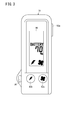
- FIG. 3 is a front view of the remote controller 16 of the vehicle 12.
- the remote controller 16 can be used for charging control (immediate charging) of the battery 30 and operation of the air conditioner 32 (immediate air conditioning operation) when the external charging device 14 is connected to the vehicle 12.
- the operation of the air conditioner 32 may be used in a state where the external charging device 14 is not connected to the vehicle 12.
- the remote controller 16 includes a communication unit 90, an operation unit 92, an electronic control device 94 (hereinafter referred to as “remote controller ECU 94” or “ECU 94”), and a display unit 96. .
- the remote controller 16 is provided with a hole 98 (FIG. 3) for hanging a strap.
- the communication unit 90 communicates with the BRU 48 of the vehicle 12 via the first antenna 50.
- the communication unit 90 is capable of two-way wireless communication with a communication distance of about several tens of meters using low-power radio waves.
- a line between the vehicle 12 and the remote controller 16 is referred to as a local line 100 (first communication line).
- the operation unit 92 includes a power switch 92a, a charge switch 92b (charge on / off switch), and an air conditioner switch 92c (air conditioner on / off switch).
- the power switch 92a is a switch for turning on / off the remote controller 16 and confirming the state of charge of the battery 30 and the vehicle interior temperature.
- the charge switch 92b is a switch for making a request for starting and ending charging of the battery 30, and the like.
- the air conditioner switch 92c is a switch for turning the air conditioner 32 on and off.
- the remote control ECU 94 controls the entire remote controller 16.
- the display unit 96 performs various displays relating to the charging of the battery 30 and the operation of the air conditioner 32.
- the vehicle state mentioned here includes the SOC [%] of the battery 30, the vehicle interior temperature [° C.], whether or not the battery 30 is being charged (including the start and end of charging), and the operation of the air conditioner 32. (Including start and end of operation).
- the remote control ECU 94 displays the received vehicle status on the display unit 96.
- the initial setting of the display is information related to charging (that is, whether or not the SOC of the battery 30 is being charged) and whether or not the air conditioner 32 is in operation.
- the air conditioner switch 92c is pressed once for a short time
- information about the air conditioner 32 that is, whether the vehicle interior temperature and the air conditioner 32 are operating
- the display is switched to information about charging and whether the air conditioner 32 is operating.
- the remote control ECU 94 turns off the remote controller 16. Accordingly, the display on the display unit 96 disappears.
- the charging switch 92 b When requesting charging of the battery 30, the charging switch 92 b is pushed once for a long time in a state where the external charging device 14 is connected to the vehicle 12. As a result, the remote control ECU 94 outputs an immediate charge command (or charge start request signal) for requesting the BRU 48 to start charging. If an environment for charging on the vehicle 12 side (for example, the external charging device 14 is connected) is ready, the vehicle 12 starts charging the battery 30 in response to the immediate charging command.
- an immediate charge command or charge start request signal
- the air conditioner switch 92c When requesting the start of the air conditioner 32, the air conditioner switch 92c is pressed once for a long time with the external charging device 14 connected to the vehicle 12. As a result, the remote control ECU 94 outputs an immediate operation command (or an air conditioner start request signal) requesting the BRU 48 to start the start of the air conditioner 32. If the environment for starting the air conditioner 32 is prepared on the vehicle 12 side (for example, the external charging device 14 is connected), the vehicle 12 starts the air conditioner 32 in response to the immediate operation command.
- the mobile communication terminal 18 is used for charging control (immediate charging) of the battery 30 and operation of the air conditioner 32 (immediate air conditioning operation) when the external charging device 14 is connected to the vehicle 12. it can. Further, the operation of the air conditioner 32 may be used in a state where the external charging device 14 is not connected to the vehicle 12. Furthermore, the portable communication terminal 18 can be used for reserving the battery 30 (reserved charging) and operating the air conditioner 32 (reserving air conditioner operation). In addition, the mobile communication terminal 18 can be used to check the state of charging of the battery 30 and the state of air conditioning by the air conditioner 32.
- the mobile communication terminal 18 does not communicate directly with the vehicle 12 but communicates with the vehicle 12 via the server 20.
- the mobile communication terminal 18 includes a communication unit 110, an operation unit 112, an electronic control device 114 (hereinafter referred to as “terminal ECU 114” or “ECU 114”), and a display unit 116.
- a communication unit 110 for example, an existing smartphone having a data communication function and a telephone function can be used.
- the mobile communication terminal 18 may be a mobile communication device such as a mobile phone, a tablet terminal, or a mobile personal computer.
- the communication unit 110 communicates with the server 20 via the Internet line 120 (second communication line) as a public line and a mobile communication line.
- the mobile communication terminal 18 of the present embodiment communicates with the vehicle 12 via the server 20.
- the operation unit 112 includes input means such as a touch panel, for example.
- the terminal ECU 114 controls the entire mobile communication terminal 18.
- the display unit 116 performs various displays related to the charging of the battery 30 and the operation or operation of the air conditioner 32, and can be configured by the touch panel or the like, for example.
- the server 20 relays communication between the vehicle 12 and the mobile communication terminal 18 and manages various information related to the vehicle 12.
- the server 20 communicates with the vehicle 12 via the Internet line 122 (third communication line) as a public line and a mobile communication line.
- the server 20 includes a vehicle state table 130 (FIG. 2) that stores vehicle state information corresponding to individual identification information such as a chassis number of the vehicle 12.
- the vehicle state table 130 in addition to the chassis number, for example, (a) the SOC of the battery 30, (b) whether the charging plug 64 is connected to the charging port 66, (c) acquired by the temperature sensor 42. Various temperatures such as cabin temperature, (d) whether or not the battery 30 is being charged (including the start and end of charging), and (e) whether or not the air conditioner 32 is being operated (operating) And the like are stored as vehicle state information. As will be described later, the vehicle state information stored in the vehicle state table 130 is updated every time new vehicle state information is received from the vehicle 12.
- Stop-time power control As described above, when the external charging device 14 is connected to the vehicle 12 when the vehicle 12 is stopped, the battery 30 is charged and the air conditioner 32 is operated by the electric power from the external charging device 14. Can do. At this time, when charging is instructed, the battery 30 can be charged both immediately by charging immediately and by reserved charging at a preset timing (time). Similarly, the operation of the air conditioner 32 includes an immediate air conditioner operation that immediately activates the air conditioner 32 when an operation instruction is given, and a reserved air conditioner operation that activates the air conditioner 32 at a preset timing (time). Can do both.
- the charging of the battery 30 is prioritized over the operation of the air conditioner 32.
- A-1) A method of connecting the charging cable 62 to the vehicle 12 without a charge reservation, and (a-2) Immediately by operating the charging switch 92b while viewing the display unit 96 of the remote controller 16 as necessary. How to output a charge command
- (B-1) A method of outputting a reserved charging command by operating the steering switch 34 while viewing the meter display unit 180, and (b-2) operating the operation unit 112 while viewing the display unit 116 of the mobile communication terminal 18.
- B-1 A method of outputting a reserved charging command by operating the steering switch 34 while viewing the meter display unit 180
- (b-2) operating the operation unit 112 while viewing the display unit 116 of the mobile communication terminal 18.
- the charge setting screen includes, for example, selection fields for ON / OFF of reservation charge, charge start time, and charge end time.
- the user operates the steering switch 34 to switch the reserved charging from OFF to ON, inputs the charging start time and the charging end time, and then performs an operation of confirming the setting change. If charging starts from the charging start time and the battery 30 becomes fully charged before the charging end time, the charging ends without waiting for the charging end time.
- C-1 A method of operating the steering switch 34 while viewing the meter display unit 180 to output an immediate operation command
- C-2 A method of outputting an immediate operation command by operating the air conditioner switch 92c while viewing the display unit 96 of the remote controller 16 as necessary
- C-3 viewing the display unit 116 of the mobile communication terminal 18. While operating the operation unit 112 while outputting an immediate operation command
- (D-1) A method of outputting a reservation operation command by operating the steering switch 34 while looking at the meter display unit 180, and (d-2) operating the operation unit 112 while looking at the display unit 116 of the mobile communication terminal 18.
- FIG. 4 is a diagram showing an example of a screen 140 (hereinafter referred to as “air conditioner setting screen 140”) used when the operation of the air conditioner 32 is reserved using the mobile communication terminal 18.
- air conditioner setting screen 140 a screen 140 used when the operation of the air conditioner 32 is reserved using the mobile communication terminal 18.
- an operation for starting the air conditioner reservation setting routine is performed by the operation unit 112.
- the air conditioner setting screen 140 is displayed on the display unit 116.
- the air conditioner setting screen 140 of this embodiment includes a weekday check box 150 (hereinafter also referred to as “check box 150”) and a weekday scheduled departure time input field 152 (hereinafter “input field 152”). ), Holiday check box 154 (hereinafter also referred to as “check box 154”), holiday departure scheduled time input field 156 (hereinafter also referred to as “input field 156”), and charging priority threshold switching permission / inhibition
- a setting field 158 hereinafter also referred to as “setting field 158”
- a charging priority threshold value input field 160 hereinafter also referred to as “input field 160”
- a confirmation button 162 are included.
- the check box 150 is an input field for turning on / off the weekday reservation setting (in other words, inputting whether or not to perform the air conditioning reservation operation on weekdays). When the check box 150 is checked, an operation reservation is made on weekdays. When there is no check, an operation reservation is not made on weekdays.
- the input column 152 is a column for inputting a scheduled sunrise departure time (for example, scheduled departure time for commuting to or from school) as an operation timing.
- a scheduled sunrise departure time for example, scheduled departure time for commuting to or from school
- the air conditioner 32 is operated for 30 minutes before the input scheduled departure time. Therefore, the scheduled departure time substantially means an operation start time and an operation end time of the air conditioner 32.
- the check box 154 is an input field for turning on / off the holiday reservation setting (in other words, inputting whether or not the holiday air conditioning reservation operation is performed). When the check box 154 is checked, a holiday operation reservation is made, and when there is no check, a holiday operation reservation is not made.
- the input column 156 is a column for inputting a scheduled departure time of a holiday (for example, a scheduled departure time for shopping or travel) as an operation timing.
- a scheduled departure time of a holiday for example, a scheduled departure time for shopping or travel
- the air conditioner 32 is operated for 30 minutes before the input scheduled departure time.
- the setting column 158 is a column for setting whether or not to switch the charging priority threshold THsoc (hereinafter also referred to as “threshold THsoc”) to a value other than 100% corresponding to full charging.
- threshold THsoc the charging priority threshold THsoc
- the charge priority threshold THsoc determines whether or not to operate the air conditioner 32 in order to prioritize charging of the battery 30 (in other words, whether or not to supply power from the external charging device 14 to the air conditioner 32). ) For determining the SOC.
- the input column 160 is a column for inputting a specific numerical value of the charging priority threshold THsoc.
- the threshold value THsoc can be switched only when “ON” is selected in the setting field 158, and when “OFF” is selected, the threshold value THsoc cannot be switched. Further, the threshold value THsoc can be selected in the range of the lowest value (for example, 50%) to 100%.
- the user inputs the threshold value THsoc.
- the ECU 114 of the mobile communication terminal 18 may automatically calculate the threshold value THsoc.
- the required power amount on each weekday is considered to be substantially equal. Therefore, it is possible to calculate the power consumption (average value) of each day on each weekday, and to calculate a value obtained by adding an error to the calculated value as the required power amount.
- a destination is input to the navigation device 38, a one-way distance or a round-trip distance from the current position of the vehicle 12 (a charging position) to the destination is calculated, and the one-way distance or the round-trip distance travels. May be calculated as a required power amount by calculating an amount of power consumption required for the above and adding an error to the calculated value.
- one or a plurality of values that are candidates for the threshold THsoc are displayed on the screen 140 after performing the automatic calculation as described above, and the user can select and decide.
- the confirmation button 162 is a button for confirming the changed setting.
- the case where the operation of the air conditioner 32 is reserved using the steering switch 34 can be the same as that of the portable communication terminal 18.
- the mobile communication terminal 18 and the steering switch 34 in this embodiment function as a scheduled departure time input unit that inputs a scheduled departure time.
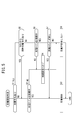
- FIG. 5 is a flowchart for determining whether to start charging the battery 30.
- FIG. 6 is a diagram illustrating the role or operation of each part when immediate charging is requested from the remote controller 16 and when reserved charging is performed in the vehicle 12.
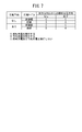
- FIG. 7 is a diagram illustrating a case where immediate charging or reserved charging is performed and a case where it is not performed.
- step S1 of FIG. 5 the battery ECU 36 determines whether or not there is a charge reservation. This determination is performed by determining whether or not a reservation setting has been received from the meter ECU 46.
- the meter ECU 46 outputs the reservation setting to the battery ECU 36 when the reservation setting is performed or at another preset timing (for example, when the vehicle 12 is stopped).
- step S2 the battery ECU 36 determines whether the charging cable 62 is being connected to the vehicle 12, in other words, whether the charging plug 64 is connected to the charging port 66. Determine whether or not. This determination is made based on the output from the charging port 66.
- the battery ECU 36 starts charging the battery 30 in step S3. Specifically, the battery ECU 36 confirms the SOC of the battery 30, and if charging is necessary, the battery ECU 36 turns on the first switch 82 and turns off the second switch 84 to the external charging device 14. To output a power transmission command requesting power supply. The external charging device 14 that has received the power transmission command supplies power to the vehicle 12 via the charging cable 62. Thereby, the battery 30 is charged.
- step S4 the battery ECU 36 displays a message for requesting connection of the charging cable 62 via the meter ECU 46 on the meter display unit 180.
- the message may be displayed on a display unit such as a display unit (not shown) of the navigation device 38 instead of or in addition to the display on the meter display unit 180.
- a message for requesting connection of the charging cable 62 may be output from a speaker (not shown).
- step S5 the battery ECU 36 determines whether or not an immediate charge command from the remote controller 16 has been received via the BRU 48.
- the immediate charging command is output when the charging switch 92b is pressed once for a long time in the remote controller 16.
- step S5 is NO.
- the immediate charge can be permitted.
- step S2 If there is an immediate charge command from the remote controller 16 (S5: YES), the process proceeds to step S2. Thereafter, the process is the same as when there is no charge reservation (S1: YES).
- step S6 the battery ECU 36 determines whether or not the charging cable 62 is being connected to the vehicle 12. This determination can be performed in the same manner as in step S2.
- step S7 the battery ECU 36 determines whether or not the reserved charging timing has come. This determination is made, for example, based on whether or not the battery ECU 36 has received an immediate charge command from the meter ECU 46.
- the meter ECU 46 confirms that the charging timing has come based on the reservation setting (timer setting) set in the timer 170 (FIG. 6) and the GPS (Global Positioning System) time from the navigation device 38, for example.
- the charging timing is reached, an immediate charging command is output to the battery ECU 36.
- step S3 charging of the battery 30 is started as described above.
- step S4 the battery ECU 36 displays a connection request message for the charging cable 62 by the method described above.
- step S8 the battery ECU 36 Do not start charging.
- the reservation setting can be confirmed on the mobile communication terminal 18.
- the following processing is performed in order to make the reservation setting that can be confirmed by the mobile communication terminal 18 the latest and to shorten the confirmation time.
- FIG. 8 is a flowchart when the reservation setting is changed through operation of the steering switch 34.
- FIG. 9 is a diagram for explaining the role or operation of each part when the reservation setting is changed through the operation of the steering switch 34.
- the meter ECU 46 changes the reservation setting related to the charging of the battery 30 or the operation of the air conditioner 32 in accordance with the operation of the steering switch 34.
- the user operates the steering switch 34 while looking at the meter display unit 180 to change the reservation setting relating to the charging of the battery 30 or the operation of the air conditioner 32.
- the change of the reservation setting here includes a change of whether or not there is a reservation.
- the changed reservation setting is recorded in the timer 170 (FIG. 9).
- reservation settings relating to charging of the battery 30 are managed by the charge reservation management function 190, and reservation settings relating to the operation of the air conditioner 32 are managed by the air conditioner reservation management function 192.
- the time measuring function 194 manages the time used for reservation management based on the GPS time from the navigation device 38.
- the meter ECU 46 transmits the new reservation setting after the change (hereinafter referred to as “reservation setting Smtr1” in FIG. 9) to the TCU 52.
- the reservation setting Smtr1 includes not only the reservation setting relating to the charging of the battery 30 or the operation of the air conditioner 32 that has actually been changed, but also the setting that has not been changed.
- the reservation setting Smtr1 may include only the reservation setting actually changed.
- step S13 the TCU 52 that has received the new reservation setting Smtr1 makes an inquiry about the predetermined state to the battery ECU 36 and the air conditioner ECU 40.
- the battery ECU 36 is inquired about the charging-related information including the SOC of the battery 30 and information on whether or not charging is in progress.
- the air conditioner ECU 40 is inquired about air conditioner-related information including the current vehicle interior temperature, whether the air conditioner 32 is in operation, and various settings of the air conditioner 32 (set temperature, air volume, etc.).
- step S14 the battery ECU 36 answers the inquiry from the TCU 52. That is, the charging related information is output to the TCU 52.
- step S15 the air conditioner ECU 40 answers the inquiry from the TCU 52. That is, the air conditioner related information is output to the TCU 52.
- step S16 the TCU 52 transmits to the server 20 vehicle state information including the reservation setting Smtr1 from the meter ECU 46, the charging related information from the battery ECU 36, and the air conditioner related information from the air conditioner ECU 40. Note that processing when communication cannot be performed between the TCU 52 and the server 20 will be described later.
- step S17 the server 20 stores the received vehicle state information (including the new reservation setting Smtr1) in the vehicle state table 130. Specifically, each item of the vehicle state is updated to the latest information. The information before update can be deleted or saved.
- step S17 when the user operates the mobile communication terminal 18 to send a vehicle state inquiry to the server 20 (S18), the server 20 answers the inquiry from the mobile communication terminal 18 in step S19. That is, the server 20 transmits the latest vehicle state information stored in the vehicle state table 130 to the mobile communication terminal 18.
- step S20 the mobile communication terminal 18 displays the received vehicle state information on the display unit 116.
- FIG. 10 is a flowchart showing processing on the vehicle 12 side when communication with the server 20 is impossible.
- step S ⁇ b> 21 the TCU 52 detects that communication with the server 20 is not possible.
- step S22 the TCU 52 stores the vehicle state in the storage unit 200 (FIG. 9).
- step S23 the TCU 52 determines the timing for retrying communication with the server 20 (retry timing).
- retry timing for example, the remote controller 16 was operated, the battery 30 was started or stopped, the air conditioner 32 was started or stopped, and other conditions were satisfied. At least one of the above.
- a signal has been input from the server 20, and the charging plug 64 is charged. It can include that it is attached to the port 66 or that the charging plug 64 has been removed from the charging port 66.
- step S23 if it is determined that no retry is required (in other words, the retry timing has not yet arrived) (S24: NO), the process returns to step S23. If it is determined that a retry is required (S24: YES), the TCU 52 reattempts communication with the server 20 in step S25.
- step S26 If communication with the server 20 is still not possible (S26: NO), the process returns to step S23.
- the TCU 52 transmits the vehicle state stored in the storage unit 200 to the server 20 in step S27.
- reservation setting Smb1 a new reservation setting
- Smb11 a new reservation setting
- the server 20 that has received the new reservation setting Smb11 stores the reservation setting Smb11 in the vehicle state table 130 and transmits it to the TCU 52 of the vehicle 12.
- the TCU 52 that has received the new reservation setting Smb11 transmits the reservation setting Smb11 to the meter ECU 46.
- the charge reservation management function 190 or the air conditioner reservation management function 192 of the meter ECU 46 inputs a new reservation setting Smb11 to the timer 170.
- the meter ECU 46 manages the charging of the battery 30 or the operation of the air conditioner 32 based on the new reservation setting Smb11.
- the user can check the reservation setting stored in the server 20 with the mobile communication terminal 18 (S18 to S20 in FIG. 8). Therefore, the reservation setting can be confirmed without waiting for communication between the server 20 and the vehicle 12, and the waiting time can be shortened and the convenience of the user can be improved.
- the changed reservation setting is transmitted from the vehicle 12 to the server 20, and the changed reservation setting is stored in the vehicle state table 130, so that the timer 170 and the vehicle state table 130 are stored.
- the reservation settings stored in each are synchronized (S11 to S17 in FIG. 8). For this reason, when there is a request from the mobile communication terminal 18, the reservation setting stored in the server 20 is the latest. Therefore, the user can confirm an accurate reservation setting, and the convenience of the user can be improved from this point.
- the remote controller 16 when the reservation setting is changed in the vehicle 12 and the communication between the vehicle 12 and the server 20 is not possible, the remote controller 16 is operated (S23 in FIG. 10) as a trigger.
- the changed reservation setting is transmitted to the server 20.
- the mobile communication terminal 18 can acquire and display information on the vehicle state table 130 from the server 20 (S18 to S20). Therefore, when there is a request from the mobile communication terminal 18, the user can check whether charging is in progress and the reservation setting only by communication between the mobile communication terminal 18 and the server 20. Therefore, the vehicle state information including the accurate reservation setting can be confirmed in a short time, and the convenience for the user can be improved.
- the remote controller 16 commands the start and stop of the air conditioner 32 in addition to commands for starting and ending charging of the battery 30.
- the remote controller 16 immediately starts or immediately ends the charging of the battery 30 or the air conditioner 32.
- the changed reservation setting is transmitted from the vehicle 12 to the server 20. Therefore, the number of communications between the vehicle 12 and the server 20 can be reduced.
- the remote controller 16 commands the immediate start of charging from the external charging device 14 to the battery 30, and even when there is a charge reservation in the vehicle 12 (S1: YES in FIG. 5), the remote controller 16 When the operation is performed (S5: YES), charging from the external charging device 14 to the battery 30 is immediately started (S3).
- S3 This makes it possible to immediately start charging the battery 30 even when there is a reservation setting related to the charging timing. Therefore, it is possible to save the user from having to cancel the reservation setting, and it is possible to improve the convenience for the user.
- the reservation setting is maintained even when immediate charging is started (permitted) (S3) when the remote controller 16 is operated (S5 in FIG. 5: YES). Therefore, it is possible to save the user from having to reset the reservation timing, and from this point, the convenience of the user can be improved.
- the power supply system 10 is for vehicles. However, from the viewpoint of synchronizing the reservation setting for charging the battery 30 or the operation of the air conditioner 32 with the server 20, the system 10 is moved other than the vehicle 12. It can also be used for devices such as bodies (for example, trains, ships, airplanes, cranes, elevators, etc.), manufacturing devices, machine tools, or household or industrial stationary power storage devices.
- bodies for example, trains, ships, airplanes, cranes, elevators, etc.
- manufacturing devices machine tools, or household or industrial stationary power storage devices.
- the power supply system 10 includes the vehicle 12, the external charging device 14, the remote controller 16, the mobile communication terminal 18, and the server 20, but reserves charging of the battery 30 or operation of the air conditioner 32.
- the configuration of the system 10 is not limited to this.
- the system 10 may be configured only by the vehicle 12, the external charging device 14, the mobile communication terminal 18, and the server 20.
- the component that receives power supply from the external power source is not limited to the air conditioner 32.
- external charging is performed on the audio device, the navigation device 38, the lighting device (headlight, etc.) of the vehicle 12, the warm-up device (heater, etc.) of the battery 30, etc. Electric power may be supplied from the device 14.
- electric power may be supplied from the external charging device 14 to a warm-up device (such as a heater) of the fuel cell and the power storage device. Then, priority can be given to the charging of the power storage device over the power supply to components other than the power storage device, or vice versa.
- a warm-up device such as a heater
- the vehicle 12 has only a travel motor (not shown) as a drive source and is an electric vehicle in a narrow sense that supplies electric power to the travel motor only from the battery 30, but the battery 30 (power storage device) As long as the vehicle can be charged from the outside, it may be an electric vehicle (for example, a plug-in hybrid vehicle, a fuel cell vehicle) other than an electric vehicle in a narrow sense.
- the power storage device to be charged is not for supplying power to the travel motor (for example, when charging a battery for an auxiliary machine), the vehicle 12 may not be an electric vehicle.
- the vehicle 12 is assumed to be a four-wheeled vehicle (see FIG. 1), but a battery 30 (power storage device) or an air conditioner 32 to which power is supplied from the external charging device 14 (external power source), etc. From the viewpoint of a vehicle including the constituent elements, it may be other than a four-wheeled vehicle.
- the vehicle 12 may be a vehicle such as a motorcycle, an automatic tricycle, or a six-wheeled vehicle.
- External charging device 14 As an external power source is assumed to be a fixed type and a cable type (see FIG. 1). However, the server 20 performs reservation setting for charging the battery 30 or operating the air conditioner 32. From the viewpoint of synchronizing with the external charging device 14, the external charging device 14 may be movable or wirelessly fed. In addition, as a case where the external charging device 14 is movable, a case where an external power source is mounted on a vehicle for power supply can be considered.
- Remote controller 16 In the above embodiment, the remote controller 16 has been described as being positioned as a dedicated device for controlling the charging of the battery 30 and the operation of the air conditioner 32. However, from the viewpoint of executing these controls, It may have a function. For example, an electronic key or smart key that locks and unlocks the door lock may have the function of the remote controller 16.
- the battery 30 supplies power to the travel motor (not shown) of the vehicle 12, but from the viewpoint of supplying power from an external power supply (external charging device 14), It may be a power storage device used for an application (for example, for supplying power to an auxiliary machine).
- Air conditioning 32 In the above embodiment, the set temperature and the air volume are given as the output setting (air conditioning condition) of the air conditioner 32. However, from the viewpoint of the air conditioning condition, it is not limited thereto. For example, only the set temperature may be set as the air conditioning condition, or the humidity may be set in addition to the set temperature and the air volume.
- the power adjustment unit 80 includes the first switch 82 and the second switch 84, and enables only one of charging the battery 30 and operating the air conditioner 32.
- the power adjustment unit 80 is a battery as in US Patent Application Publication No. 2012/0101659 (hereinafter referred to as “US 2012/01016659 A1”). It may be configured such that both charging to 30 and the operation of the air conditioner 32 are performed simultaneously (see [0028] of US 2012/0106659 A1).
- Vehicle state table 130 In the above embodiment, the vehicle state stored in the vehicle state table 130 is updated (overwritten). However, in addition to the latest vehicle state, past vehicle states may be accumulated.
- the steering switch is used as a setting means for setting the charging of the battery 30 and the operation of the air conditioner 32 among the components mounted on the vehicle 12. 34 is used, but it is not limited to this in terms of performing the setting.
- input means such as a touch panel (not shown) of the navigation device 38 may be used instead of or in addition to the steering switch 34.
- the command from the mobile communication terminal 18 is transmitted to the vehicle 12 via the server 20.
- the component that directly performs the setting related to the charging of the battery 30 and the operation of the air conditioner 32 from the outside of the vehicle 12 is the server 20.
- the changed reservation setting may be transmitted from the vehicle 12 to the server 20, and the reservation setting of the server 20 may be updated.
- Reservation setting [10-1. Reservation setting for charging battery 30 (battery reservation operation)]
- reservation charging on / off, charging start time, and charging end time are used as the reservation setting for charging (see FIG. 4), but this is not limited from the viewpoint of reserving charging timing.
- only one of charging start time or charging end time may be used. When only the charging start time is input, the charging is continued until the battery 30 is fully charged or reaches the charging priority threshold THsoc.
- the battery ECU 36 determines the SOC of the battery 30 at the time of full charge or the threshold THsoc (fixed value or deterioration).
- the charging start time may be calculated based on the variable output according to the degree), the possible output of the external charging device 14, and the like.
- the calculating means determines whether the charging timing and the operation timing of the air conditioner 32 are compatible. It may be determined (whether the charging timing and the operation timing do not overlap), and the charging start time may be advanced according to the determination result.
- the battery 30 When it is determined that compatibility is possible, after the battery 30 is fully charged or after the SOC of the battery 30 is set to the charge priority threshold THsoc, power is supplied to the air conditioner 32 and it is determined that compatibility is not possible
- the battery 30 is charged from the external charging device 14 until the SOC exceeds the threshold value THsoc, and after the SOC exceeds the threshold value THsoc, the power supply from the external charging device 14 to the air conditioner 32 can be performed.
- Air-conditioner 32 reservation setting (air-conditioner reservation operation)
- the content that can be input by the mobile communication terminal 18 is as shown in FIG. 4, but is not limited thereto as described in detail below.
- the scheduled departure time is input separately for weekdays and holidays, but this is not a limitation from the viewpoint of setting the operating time of the air conditioner 32. For example, it is possible not to divide weekdays and holidays, set for each day of the week, or set for each day. Alternatively, instead of or in addition to the scheduled departure time, the operating time of the air conditioner 32 (for example, “from what hour to what hour”, “from what hour to what minute” or “scheduled departure time”) It is also possible to set “acting for several minutes before”.
- output settings such as the set temperature and air volume of the air conditioner 32 could not be input on the air conditioner setting screen 140 of FIG. 4, but these may be input. These input settings may be set separately from the initial setting of the air conditioner 32 (setting when the vehicle 12 is stopped or setting used last in the vehicle 12), or the initial setting The setting may be updated.
- the air conditioner 32 is operated according to the setting by the user (that is, the setting in the operating means of the air conditioner 32 or the setting input by the mobile communication terminal 18). At the same time, it is possible to apply the power obtained by subtracting the power consumption of the air conditioner 32 from the power supplied from the external charging device 14 to charge the battery 30.
- the SOC when the SOC is lower than the threshold THsoc, charging is prioritized over the air conditioner 32.
- the SOC is higher than the threshold THsoc, from the viewpoint that the operation of the air conditioner 32 is prioritized over charging, the SOC is lower than the threshold THsoc. It is possible to perform both the charging of the battery 30 and the operation of the air conditioner 32 both in the case where it falls below and above the THsoc. In this case, if the SOC is lower than the threshold THsoc, the air conditioner 32 charges the battery 30 in a state where the output is lower than the setting by the user (for example, the minimum output or the output reduced by a predetermined rate). I do.
- the air conditioner 32 is operated according to the setting by the user (with an output as requested by the user), and the consumption of the air conditioner 32 from the power supplied from the external charging device 14 is performed. It is also possible to apply the electric power minus the electric power to charge the battery 30. In these cases as well, charging of the battery 30 and the operation of the air conditioner 32 can be performed in a well-balanced manner by using the charging priority threshold THsoc that can be set by the user.
- the threshold THsoc is variable.
- the threshold value THsoc when the SOC is lower than the threshold value THsoc, the output of the air conditioner 32 is limited.
- the threshold value THsoc may be a fixed value (for example, a value indicating full charge).
- the air conditioner 32 when the SOC of the battery 30 is lower than the threshold value THsoc, the air conditioner 32 is not operated and the charging to the battery 30 is prioritized.
- priority is given to the operation of the air conditioner 32 over the charging of the battery 30 even when the SOC of the battery 30 is lower than the threshold value THsoc.
- You may set the air-conditioner priority mode.
- the setting of the air conditioner priority mode can be performed using, for example, the steering switch 34, the remote controller 16, the portable communication terminal 18, or the like as the air conditioner priority mode setting unit.
- the target reservation setting is the charging of the battery 30.
- the reservation setting that can be confirmed by the mobile communication terminal 18 may be only one of charging of the battery 30 or the operation of the air conditioner 32.
- reservation setting Smtr1 reservation setting Smtr1 changed in the vehicle 12 to the server 20 to synchronize the reservation setting between the vehicle 12 and the server 20, as long as there is a charge reservation for the battery 30, it is immediately charged.
- reservation setting Smtr1 reservation setting Smtr1 changed in the vehicle 12 to the server 20 to synchronize the reservation setting between the vehicle 12 and the server 20
Landscapes
- Engineering & Computer Science (AREA)
- Power Engineering (AREA)
- Transportation (AREA)
- Mechanical Engineering (AREA)
- Life Sciences & Earth Sciences (AREA)
- Sustainable Development (AREA)
- Sustainable Energy (AREA)
- Electric Propulsion And Braking For Vehicles (AREA)
- Charge And Discharge Circuits For Batteries Or The Like (AREA)
- Remote Monitoring And Control Of Power-Distribution Networks (AREA)
- Secondary Cells (AREA)
Description
この発明は、外部電源から車両の蓄電装置への充電タイミングに関する予約設定を、サーバを介して携帯通信端末により変更可能な充電システムに関する。
米国特許出願公開第2012/0086395号公報(以下「US 2012/0086395 A1」という。)には、自動車のバッテリの充電を制御する技術が開示されている(要約)。
より具体的には、US 2012/0086395 A1では、充電所で充電プラグを車両に差し込むと、バッテリの充電を開始する([0041]、図3のステップ310)。また、バッテリ充電が行われる間、バッテリSOC(State of Charge)、充電完了予想時間及び走行可能距離の情報を管制サーバ200に送信する([0043]、[0044]、ステップ320)。管制サーバ200は、遠隔端末300からの要求に応じてこれらの情報を遠隔端末300に提供する([0045]、ステップ330)。これにより、運転者は、当該情報をモニタリングすることができる([0045])。
なお、US 2012/0086395 A1では、自動車のテレマティクス装置100が、管制サーバ200から予約情報を受信すると、当該時間に自動に予約充電を行う([0028])。また、遠隔端末300は、運転者のキー操作に従い遠隔制御信号を発生させ、管制サーバ200を介しテレマティクス装置100へ伝送する([0030])。
上記のように、US 2012/0086395 A1では、遠隔端末300において、バッテリを充電している間の情報がモニタリングされる([0045])。しかしながら、US 2012/0086395 A1では、バッテリの充電予約に関する記載がほとんどなく、充電予約に関するユーザの利便性について詳細な検討はされていない。
この発明はこのような課題を考慮してなされたものであり、充電予約に関するユーザの利便性を向上することが可能な車両用充電システムを提供することを目的とする。
この発明に係る車両用充電システムは、外部電源から車両の蓄電装置への充電タイミングに関する予約設定を、サーバを介して携帯通信端末により変更可能なものであって、前記車両は、前記予約設定を記憶する第1記憶部を備え、前記サーバは、前記予約設定を記憶する第2記憶部を備え、前記携帯通信端末から前記予約設定の送信要求があったとき、前記サーバは、前記第2記憶部に記憶されている前記予約設定を前記携帯通信端末に送信し、前記携帯通信端末は、受信した前記予約設定を表示し、前記車両において前記予約設定が変更されたとき、前記車両から前記サーバに変更後の予約設定を送信して前記第2記憶部に前記変更後の予約設定を記憶させて、前記第1記憶部及び前記第2記憶部それぞれに記憶される前記予約設定を同期させることを特徴とする。
この発明によれば、ユーザは、サーバに記憶されている予約設定を携帯通信端末で確認することができる。従って、サーバと車両の間の通信を待たずに予約設定を確認することが可能となり、待ち時間を短縮してユーザの利便性を向上することが可能となる。
また、サーバに記憶されている予約設定は、その時点で車両に記憶されているものと同期している。このため、携帯通信端末から要求があった際、サーバに記憶されている予約設定は最新のものとなる。従って、ユーザは、正確な予約設定を確認することができ、この点からもユーザの利便性を向上することが可能となる。
前記充電システムは、前記外部電源から前記蓄電装置への充電の即時開始又は即時終了を指令し且つ前記携帯通信端末とは別体のリモートコントローラを備え、前記車両において前記予約設定が変更された時点で、前記車両と前記サーバとの通信ができない場合、前記リモートコントローラが操作されたことを契機として、前記車両から前記サーバに変更後の予約設定を送信してもよい。
これにより、リモートコントローラにおいて、蓄電装置への充電の即時開始又は即時終了が指令された際に、車両からサーバに変更後の予約設定を送信する。従って、例えば、変更後の予約設定と共に、リモートコントローラの操作に伴う情報(例えば、充電の開始又は終了)を送信する構成とすれば、車両とサーバとの間の通信回数を減らすことが可能となる。
前記リモートコントローラが、前記外部電源から前記蓄電装置への充電の即時開始を指令する場合、前記第2記憶部は、前記蓄電装置が充電中であるか否かの情報を前記予約設定と共に車両状態情報として記憶し、前記携帯通信端末から前記車両状態情報の送信要求があったとき、前記サーバは、前記第2記憶部に記憶されている前記車両状態情報を前記携帯通信端末に送信し、前記携帯通信端末は、受信した前記車両状態情報を表示し、前記車両において前記予約設定が変更された時点で、前記車両と前記サーバとの通信ができない場合、前記リモートコントローラにより前記充電の即時開始が指令されたことを契機として、変更後の予約設定を含む前記車両状態情報を前記車両から前記サーバに送信してもよい。
これにより、リモートコントローラにおいて、蓄電装置への充電の即時開始が指令された際に、車両からサーバに変更後の予約設定を送信する。従って、例えば、変更後の予約設定と共に、リモートコントローラの操作に伴う情報(例えば、充電の開始)を送信する構成とすれば、車両とサーバとの間の通信回数を減らすことが可能となる。また、携帯通信端末から要求した際、ユーザは、充電中であるか否か及び予約設定を、携帯通信端末とサーバとの間の通信のみで確認することが可能となる。従って、ユーザは、充電の開始及び正確な予約設定を短時間で確認することができ、ユーザの利便性を向上することが可能となる。
前記リモートコントローラは、さらに、前記車両のエアコンディショナの始動又は停止を指令してもよい。これにより、リモートコントローラが操作されたことを契機として予約設定を再送信する構成では、リモートコントローラにおいて、蓄電装置への充電の即時開始若しくは即時終了又はエアコンディショナの始動若しくは停止が指令された際に、車両からサーバに変更後の予約設定を送信する。従って、例えば、変更後の予約設定と共に、リモートコントローラの操作に伴う情報(例えば、充電の開始若しくは終了又はエアコンディショナの始動若しくは停止)を送信する構成とすれば、車両とサーバとの間の通信回数を減らすことが可能となる。
前記リモートコントローラが、前記外部電源から前記蓄電装置への充電の即時開始を指令する場合、前記車両において前記予約設定が存在する場合でも、前記リモートコントローラが操作されたことを契機として、前記外部電源から前記蓄電装置への充電を即時に開始すると共に、前記車両における前記予約設定を維持してもよい。これにより、充電タイミングに関する予約設定が存在する場合でも、蓄電装置への充電を即時に開始することが可能となる。従って、ユーザによる予約設定の解除の手間を省くことができ、ユーザの利便性を向上することが可能となる。また、即時充電を開始(許可)する場合であっても、予約設定を維持する。従って、ユーザによる予約タイミングの再設定の手間を省くことができ、この点からも、ユーザの利便性を向上することが可能となる。
この発明に係る充電システムは、外部電源から車両の蓄電装置への充電タイミングに関する予約設定を、サーバを介して携帯通信端末により変更可能なものであって、前記車両は、前記予約設定を記憶する第1記憶部を備え、前記サーバは、前記予約設定を記憶する第2記憶部を備え、前記携帯通信端末から前記予約設定の送信要求があったとき、前記サーバは、前記第2記憶部に記憶されている前記予約設定を前記携帯通信端末に送信し、前記携帯通信端末は、受信した前記予約設定を表示することを特徴とする。
この発明によれば、ユーザは、サーバに記憶されている予約設定を携帯通信端末で確認することができる。従って、サーバと車両の間の通信を待たずに予約設定を確認することが可能となり、待ち時間を短縮してユーザの利便性を向上することが可能となる。
A.一実施形態
1.構成
[1-1.車両用電力供給システム10の全体構成]
図1は、この発明の一実施形態に係る車両用充電システムとしての車両用電力供給システム10(以下「電力供給システム10」又は「システム10」ともいう。)のブロック構成図である。図2は、システム10の各構成要素のブロック図である。システム10は、車両12と、外部充電装置14と、リモートコントローラ16と、携帯通信端末18と、サーバ20とを有する。なお、図1及び図2では、システム10が各構成要素を1つずつ有する構成を示しているが、システム10が構成要素のいずれかを複数有する構成(例えば、1台のサーバ20と、複数の車両12、外部充電装置14、リモートコントローラ16及び携帯通信端末18とが対応付けられた構成)も可能である。
1.構成
[1-1.車両用電力供給システム10の全体構成]
図1は、この発明の一実施形態に係る車両用充電システムとしての車両用電力供給システム10(以下「電力供給システム10」又は「システム10」ともいう。)のブロック構成図である。図2は、システム10の各構成要素のブロック図である。システム10は、車両12と、外部充電装置14と、リモートコントローラ16と、携帯通信端末18と、サーバ20とを有する。なお、図1及び図2では、システム10が各構成要素を1つずつ有する構成を示しているが、システム10が構成要素のいずれかを複数有する構成(例えば、1台のサーバ20と、複数の車両12、外部充電装置14、リモートコントローラ16及び携帯通信端末18とが対応付けられた構成)も可能である。
システム10では、車両12が停車し、外部充電装置14と接続されている際、バッテリ30(図2)の充電及びエアコンディショナ32の作動のために外部充電装置14からの電力を利用することができる。バッテリ30の充電及びエアコンディショナ32の作動は、車両12のステアリングスイッチ34、リモートコントローラ16又は携帯通信端末18に対するユーザの操作により制御することができる。携帯通信端末18を介して操作をする際、車両12と携帯通信端末18との間の通信は、サーバ20を介して行われる。
なお、図面中及び以下では、「エアコンディショナ」のことを「エアコン」と省略し、「リモートコントローラ」のことを「リモコン」と省略する場合がある。
[1-2.車両12]
(1-2-1.車両12の全体構成)
車両12は、駆動源として走行モータ(図示せず)のみを有し、当該走行モータに対する電力をバッテリ30(蓄電装置)のみから供給する狭義の電気自動車である。車両12は、プラグインハイブリッド車、燃料電池車両等の電動車両であってもよい。
(1-2-1.車両12の全体構成)
車両12は、駆動源として走行モータ(図示せず)のみを有し、当該走行モータに対する電力をバッテリ30(蓄電装置)のみから供給する狭義の電気自動車である。車両12は、プラグインハイブリッド車、燃料電池車両等の電動車両であってもよい。
車両12の走行時には、バッテリ30からの電力により、前記走行モータを駆動すると共に、ユーザの操作に応じてエアコンディショナ32を作動させる。
車両12が停車し、外部充電装置14を車両12に接続している際、外部充電装置14からの電力により、バッテリ30への充電及びエアコンディショナ32の作動を選択的に行うことができる。後述するように、本実施形態では、バッテリ30への充電及びエアコンディショナ32の作動を切り替えて行い、両者を同時に行うことはない(但し、後述するように、両者を同時に実行することも可能である。)。
図2に示すように、車両12は、バッテリ30、エアコンディショナ32及びステアリングスイッチ34に加え、バッテリ電子制御装置36(以下「バッテリECU36」という。)と、ナビゲーション装置38と、エアコン電子制御装置40(以下「エアコンECU40」という。)と、温度センサ42と、メータ44と、メータ電子制御装置46(以下「メータECU46」という。)と、双方向リモコンユニット48{以下「BRU48」(BRU:Bidirectional Remote-control Communication Unit)という。}と、第1アンテナ50と、テレマティクス制御ユニット52{以下「TCU52」(TCU:Telematics Control Unit)という。}と、第2アンテナ54とを有する。ECU36、40、46、BRU48及びTCU52のそれぞれは、入出力部、演算部及び記憶部を有する。メータ44は、車速、バッテリ30の残容量(SOC:State of Charge)等を示す。
(1-2-2.電力系)
車両12では、主としてバッテリ30が電力源となる。バッテリ30は、複数のバッテリセルを含む蓄電装置(エネルギストレージ)であり、例えば、リチウムイオン2次電池又はニッケル水素2次電池を利用することができる。或いは、充放電可能な蓄電装置という観点からすれば、バッテリ30の代わりに又はバッテリ30に加えてその他の蓄電装置(例えば、キャパシタ)を用いてもよい。
車両12では、主としてバッテリ30が電力源となる。バッテリ30は、複数のバッテリセルを含む蓄電装置(エネルギストレージ)であり、例えば、リチウムイオン2次電池又はニッケル水素2次電池を利用することができる。或いは、充放電可能な蓄電装置という観点からすれば、バッテリ30の代わりに又はバッテリ30に加えてその他の蓄電装置(例えば、キャパシタ)を用いてもよい。
外部充電装置14が車両12に接続されていないとき(例えば、車両12の走行時)には、車内電力線60を介してエアコンディショナ32等の車両12の各部にバッテリ30から電力が供給される。
車両12が停車し、外部充電装置14の充電ケーブル62(以下「ケーブル62」ともいう。)の一端に設けられた充電プラグ64とバッテリ30の充電ポート66とが接続されているとき、充電ケーブル62に含まれる車外電力線68及び車両12の車内電力線60を介してバッテリ30、エアコンディショナ32等の車両12の各部に外部充電装置14から電力が供給される。ケーブル62は、車外電力線68と車外通信線70とを含む。車外通信線70は、車両12の車内通信線72に接続される。
車内電力線60上には、外部充電装置14とバッテリ30との間の第1スイッチ82と、外部充電装置14とエアコンディショナ32との間の第2スイッチ84とを含む電力調整部80が設けられている。本実施形態において、第1スイッチ82及び第2スイッチ84は、バッテリECU36又はメータECU46によりオンオフ制御される。その他の制御装置(例えば、エアコンECU40)により第1スイッチ82及び第2スイッチ84をオンオフしてもよい。
本実施形態では、ユーザがステアリングスイッチ34、リモートコントローラ16又は携帯通信端末18を操作することにより、バッテリ30の充電を制御することができる。具体的には、ステアリングスイッチ34により、充電の開始及び終了、後述する充電優先閾値THsocの設定並びに充電タイミング(充電時間)の予約設定を制御可能である。また、リモートコントローラ16により、充電の開始及び終了を制御可能である。さらに、携帯通信端末18により、充電の開始及び終了、充電優先閾値THsocの設定並びに充電タイミングの予約設定を制御可能である。これらの制御の詳細は、後述する。本実施形態のステアリングスイッチ34及び携帯通信端末18は、充電優先閾値THsocを切り替える閾値切替部として機能する。
(1-2-3.空調系)
車両12の車室内の空気調整は、主としてエアコンディショナ32により行われる。エアコンディショナ32は、ステアリングスイッチ34又は図示しない操作スイッチ等の操作手段により制御される。エアコンディショナ32の動作は、エアコンECU40により制御される。その際、エアコンECU40は、温度センサ42が検出した車室内温度を用いる。
車両12の車室内の空気調整は、主としてエアコンディショナ32により行われる。エアコンディショナ32は、ステアリングスイッチ34又は図示しない操作スイッチ等の操作手段により制御される。エアコンディショナ32の動作は、エアコンECU40により制御される。その際、エアコンECU40は、温度センサ42が検出した車室内温度を用いる。
バッテリ30の充電と同様、本実施形態では、ユーザがステアリングスイッチ34、リモートコントローラ16又は携帯通信端末18を操作することによりエアコンディショナ32の作動を制御することができる。具体的には、ステアリングスイッチ34により、エアコンディショナ32のオンオフ、設定温度、設定風量及び作動タイミング(作動時間)の予約設定を制御可能である。また、リモートコントローラ16により、エアコンディショナ32のオンオフを制御可能である。さらに、携帯通信端末18により、エアコンディショナ32のオンオフ及び作動タイミングの予約設定を制御可能である。これらの制御の詳細は、後述する。
(1-2-4.通信系)
車両12は、BRU48及び第1アンテナ50を用いて、リモートコントローラ16と双方向通信を行う。また、車両12は、TCU52及び第2アンテナ54を用いて、サーバ20と双方向通信を行う。第1アンテナ50及び第2アンテナ54は、空中線である。リモートコントローラ16又はサーバ20と車両12との通信は、バッテリ30の充電又はエアコンディショナ32の作動の際等に実行される。
車両12は、BRU48及び第1アンテナ50を用いて、リモートコントローラ16と双方向通信を行う。また、車両12は、TCU52及び第2アンテナ54を用いて、サーバ20と双方向通信を行う。第1アンテナ50及び第2アンテナ54は、空中線である。リモートコントローラ16又はサーバ20と車両12との通信は、バッテリ30の充電又はエアコンディショナ32の作動の際等に実行される。
[1-3.外部充電装置14]
外部電源としての外部充電装置14は、車両12からの要求に応じて車両12に電力を供給する。外部充電装置14は、いわゆる通常充電及び急速充電の両方が可能であるが、一方のみを実行可能であってもよい。なお、図2では、通常充電及び急速充電の両方を行うための回路が示されていないが、これは充電用の配線を簡略化して記載しているためであることに留意されたい。
外部電源としての外部充電装置14は、車両12からの要求に応じて車両12に電力を供給する。外部充電装置14は、いわゆる通常充電及び急速充電の両方が可能であるが、一方のみを実行可能であってもよい。なお、図2では、通常充電及び急速充電の両方を行うための回路が示されていないが、これは充電用の配線を簡略化して記載しているためであることに留意されたい。
外部充電装置14は、上述した充電ケーブル62及び充電プラグ64に加え、本体部86(図1)が含まれる。充電プラグ64は、ケーブル62を通じて車両12の充電ポート66に着脱自在に接続される。
[1-4.リモートコントローラ16]
(1-4-1.リモートコントローラ16の構成)
図3は、車両12のリモートコントローラ16の正面図である。上記のように、リモートコントローラ16は、外部充電装置14を車両12に接続している際におけるバッテリ30の充電制御(即時充電)及びエアコンディショナ32の操作(即時エアコン作動)に用いることができる。エアコンディショナ32の操作については、外部充電装置14を車両12に接続していない状態で用いてもよい。
(1-4-1.リモートコントローラ16の構成)
図3は、車両12のリモートコントローラ16の正面図である。上記のように、リモートコントローラ16は、外部充電装置14を車両12に接続している際におけるバッテリ30の充電制御(即時充電)及びエアコンディショナ32の操作(即時エアコン作動)に用いることができる。エアコンディショナ32の操作については、外部充電装置14を車両12に接続していない状態で用いてもよい。
図2及び図3に示すように、リモートコントローラ16は、通信部90と、操作部92と、電子制御装置94(以下「リモコンECU94」又は「ECU94」という。)と、表示部96とを有する。なお、リモートコントローラ16には、ストラップを掛ける孔部98(図3)が設けられている。
通信部90は、第1アンテナ50を介して車両12のBRU48と通信する。通信部90は、小電力電波を利用した交信距離が数十メートル程度の双方向無線方式の通信が可能である。車両12とリモートコントローラ16との回線を局所回線100(第1通信回線)という。
操作部92は、電源スイッチ92aと、充電スイッチ92b(充電オンオフ切替スイッチ)と、エアコンスイッチ92c(エアコンオンオフ切替スイッチ)とを含む。
電源スイッチ92aは、リモートコントローラ16のオンオフを行うと共に、バッテリ30の充電状態及び車室内温度を確認するためのスイッチである。充電スイッチ92bは、バッテリ30の充電の開始及び終了の要求等を行うためのスイッチである。エアコンスイッチ92cは、エアコンディショナ32のオンオフ等を行うためのスイッチである。
リモコンECU94は、リモートコントローラ16全体を制御する。表示部96は、バッテリ30の充電及びエアコンディショナ32の操作に関する各種の表示を行う。
(1-4-2.リモートコントローラ16の操作)
リモートコントローラ16がオフの状態で電源スイッチ92aを1回押すと、リモートコントローラ16がオンになると共に、リモートコントローラ16は、車両12のBRU48に対して車両状態の問い合わせを行う車両状態要求信号を出力する。ここにいう車両状態には、バッテリ30のSOC[%]、車室内温度[℃]、バッテリ30の充電中であるか否か(充電の開始及び終了を含む。)及びエアコンディショナ32の作動中であるか否か(作動の開始及び終了を含む。)が含まれる。
リモートコントローラ16がオフの状態で電源スイッチ92aを1回押すと、リモートコントローラ16がオンになると共に、リモートコントローラ16は、車両12のBRU48に対して車両状態の問い合わせを行う車両状態要求信号を出力する。ここにいう車両状態には、バッテリ30のSOC[%]、車室内温度[℃]、バッテリ30の充電中であるか否か(充電の開始及び終了を含む。)及びエアコンディショナ32の作動中であるか否か(作動の開始及び終了を含む。)が含まれる。
BRU48から上記車両状態の回答を受信すると、リモコンECU94は、受信した車両状態を表示部96に表示する。表示の初期設定は、充電に関する情報(すなわち、バッテリ30のSOC及び充電中であるか否か)並びにエアコンディショナ32が作動中であるか否かの表示である。ここで、エアコンスイッチ92cを短い時間1回押すと、エアコンディショナ32に関する情報(すなわち、車室内温度及びエアコンディショナ32が作動中であるか否か)並びに充電中であるか否かの表示に切り替わる。また、エアコンディショナ32に関する情報が表示されている状態で、充電スイッチ92bを短い時間1回押すと、充電に関する情報及びエアコンディショナ32が作動中であるか否かの表示に切り替わる。
なお、リモートコントローラ16の各スイッチ92a~92cのいずれもが所定時間(例えば、15秒間)操作されない場合、リモコンECU94は、リモートコントローラ16をオフにする。これに伴い、表示部96の表示は消える。
バッテリ30の充電を要求する場合、外部充電装置14を車両12に接続させた状態で充電スイッチ92bを長い時間1回押す。これにより、リモコンECU94は、BRU48に対して充電の開始を要求する即時充電指令(又は充電開始要求信号)を出力する。車両12側で充電を行う環境(例えば、外部充電装置14が接続されていること)が整っていれば、前記即時充電指令を受けて、車両12は、バッテリ30の充電を開始する。
エアコンディショナ32の始動を要求する場合、外部充電装置14を車両12に接続させた状態でエアコンスイッチ92cを長い時間1回押す。これにより、リモコンECU94は、BRU48に対してエアコンディショナ32の始動の開始を要求する即時作動指令(又はエアコン始動要求信号)を出力する。車両12側でエアコンディショナ32を始動させる環境(例えば、外部充電装置14が接続されていること)が整っていれば、前記即時作動指令を受けて、車両12は、エアコンディショナ32を始動させる。
[1-5.携帯通信端末18]
上記のように、携帯通信端末18は、外部充電装置14を車両12に接続している際におけるバッテリ30の充電制御(即時充電)及びエアコンディショナ32の操作(即時エアコン作動)に用いることができる。さらに、エアコンディショナ32の操作については、外部充電装置14を車両12に接続していない状態で用いてもよい。さらにまた、携帯通信端末18は、バッテリ30の充電の予約(予約充電)及びエアコンディショナ32の操作(予約エアコン作動)に用いることができる。加えて、携帯通信端末18は、バッテリ30の充電の状況及びエアコンディショナ32による空調の状況を確認するために用いることができる。
上記のように、携帯通信端末18は、外部充電装置14を車両12に接続している際におけるバッテリ30の充電制御(即時充電)及びエアコンディショナ32の操作(即時エアコン作動)に用いることができる。さらに、エアコンディショナ32の操作については、外部充電装置14を車両12に接続していない状態で用いてもよい。さらにまた、携帯通信端末18は、バッテリ30の充電の予約(予約充電)及びエアコンディショナ32の操作(予約エアコン作動)に用いることができる。加えて、携帯通信端末18は、バッテリ30の充電の状況及びエアコンディショナ32による空調の状況を確認するために用いることができる。
本実施形態では、携帯通信端末18は、車両12との間で直接通信を行うのではなく、サーバ20を介して車両12との間で通信を行う。
図2に示すように、携帯通信端末18は、通信部110と、操作部112と、電子制御装置114(以下「端末ECU114」又は「ECU114」という。)と、表示部116とを有する。本実施形態の携帯通信端末18は、例えば、データ通信機能及び電話機能等を備える既存のスマートフォンを用いることができる。或いは、携帯通信端末18は、携帯電話、タブレット端末又はモバイルパーソナルコンピュータ等の携帯通信機器であってもよい。
通信部110は、公衆回線及び移動通信回線としてのインターネット回線120(第2通信回線)を介してサーバ20と通信する。上記のように、本実施形態の携帯通信端末18は、サーバ20を介して車両12と通信する。操作部112は、例えば、タッチパネル等の入力手段を含む。
端末ECU114は、携帯通信端末18全体を制御する。表示部116は、バッテリ30の充電及びエアコンディショナ32の作動又は操作に関する各種の表示を行うものであり、例えば、上記タッチパネル等により構成することができる。
[1-6.サーバ20]
サーバ20は、車両12と携帯通信端末18との間の通信を中継すると共に、車両12に関する各種情報を管理する。サーバ20は、公衆回線及び移動通信回線としてのインターネット回線122(第3通信回線)を介して車両12と通信する。サーバ20は、車両12の車台番号等の個別識別情報に対応して車両状態情報を記憶する車両状態テーブル130(図2)を備える。
サーバ20は、車両12と携帯通信端末18との間の通信を中継すると共に、車両12に関する各種情報を管理する。サーバ20は、公衆回線及び移動通信回線としてのインターネット回線122(第3通信回線)を介して車両12と通信する。サーバ20は、車両12の車台番号等の個別識別情報に対応して車両状態情報を記憶する車両状態テーブル130(図2)を備える。
車両状態テーブル130には、車台番号に加え、例えば、(a)バッテリ30のSOC、(b)充電ポート66に充電プラグ64が接続されているか否か、(c)温度センサ42で取得された車室内温度等の各種温度、(d)バッテリ30が充電中であるか否か(充電の開始及び終了を含む。)、及び(e)エアコンディショナ32が作動中であるか否か(作動の開始及び終了を含む。)等が、車両状態情報として記憶される。後述するように、車両状態テーブル130に記憶されている上記の車両状態情報は、車両12から新たな車両状態情報を受信する度に更新される。
2.停車時電力制御
[2-1.概要]
上記のように、車両12が停止している際、外部充電装置14が車両12に接続されていれば、外部充電装置14からの電力によりバッテリ30の充電及びエアコンディショナ32の作動を行うことができる。この際、バッテリ30の充電は、充電の指示があった際、直ぐに充電を開始する即時充電と、予め設定したタイミング(時刻)に充電を行う予約充電の両方を行うことができる。同様に、エアコンディショナ32の作動は、作動の指示があった際、直ぐにエアコンディショナ32を作動させる即時エアコン作動と、予め設定したタイミング(時刻)にエアコンディショナ32を作動させる予約エアコン作動の両方を行うことができる。
[2-1.概要]
上記のように、車両12が停止している際、外部充電装置14が車両12に接続されていれば、外部充電装置14からの電力によりバッテリ30の充電及びエアコンディショナ32の作動を行うことができる。この際、バッテリ30の充電は、充電の指示があった際、直ぐに充電を開始する即時充電と、予め設定したタイミング(時刻)に充電を行う予約充電の両方を行うことができる。同様に、エアコンディショナ32の作動は、作動の指示があった際、直ぐにエアコンディショナ32を作動させる即時エアコン作動と、予め設定したタイミング(時刻)にエアコンディショナ32を作動させる予約エアコン作動の両方を行うことができる。
上記のように、本実施形態では、第1スイッチ82及び第2スイッチ84のオンオフを切り替えることにより、バッテリ30の充電及びエアコンディショナ32の一方のみを作動させ、同時に両方を行うことはない。また、本実施形態では、エアコンディショナ32の作動よりもバッテリ30の充電を優先する。
[2-2.即時充電及び予約充電]
即時充電を行う方法として、本実施形態では次の2つの方法がある。
(a-1)充電予約がない状態で充電ケーブル62を車両12に接続する方法、及び
(a-2)必要に応じてリモートコントローラ16の表示部96を見ながら充電スイッチ92bを操作して即時充電指令を出力する方法
即時充電を行う方法として、本実施形態では次の2つの方法がある。
(a-1)充電予約がない状態で充電ケーブル62を車両12に接続する方法、及び
(a-2)必要に応じてリモートコントローラ16の表示部96を見ながら充電スイッチ92bを操作して即時充電指令を出力する方法
予約充電を行う方法として、本実施形態では次の2つの方法がある。
(b-1)メータ表示部180を見ながらステアリングスイッチ34を操作して予約充電指令を出力する方法、及び
(b-2)携帯通信端末18の表示部116を見ながら操作部112を操作して予約充電指令を出力する方法
(b-1)メータ表示部180を見ながらステアリングスイッチ34を操作して予約充電指令を出力する方法、及び
(b-2)携帯通信端末18の表示部116を見ながら操作部112を操作して予約充電指令を出力する方法
ステアリングスイッチ34を用いてバッテリ30の充電を予約する場合、まずステアリングスイッチ34で充電設定ルーチンを開始させるための操作(充電設定開始操作)を行う。これにより、メータ表示部180に充電設定画面(図示せず)が表示される。
充電設定画面は、例えば、予約充電のオンオフ、充電開始時刻及び充電終了時刻の選択欄を含む。ユーザは、ステアリングスイッチ34を操作して、予約充電をオフからオンに切り替えると共に、充電開始時刻及び充電終了時刻を入力し、その後、設定変更を確定する操作を行う。なお、充電開始時刻から充電を開始して、充電終了時刻よりも前にバッテリ30が満充電になれば、充電終了時刻を待たずに充電を終了する。
充電予約を解除又は変更する場合、前記充電設定開始操作を行った後、前記充電設定画面において、充電予約を解除又は変更する操作を行う。
携帯通信端末18を用いてバッテリ30の充電を予約する場合も、ステアリングスイッチ34の場合と同様とすることができる。
[2-3.即時エアコン作動及び予約エアコン作動]
即時エアコン作動を行う方法として、本実施形態では次の3つの方法がある。
(c-1)メータ表示部180を見ながらステアリングスイッチ34を操作して即時作動指令を出力する方法、
(c-2)必要に応じてリモートコントローラ16の表示部96を見ながらエアコンスイッチ92cを操作して即時作動指令を出力する方法、及び
(c-3)携帯通信端末18の表示部116を見ながら操作部112を操作して即時作動指令を出力する方法
即時エアコン作動を行う方法として、本実施形態では次の3つの方法がある。
(c-1)メータ表示部180を見ながらステアリングスイッチ34を操作して即時作動指令を出力する方法、
(c-2)必要に応じてリモートコントローラ16の表示部96を見ながらエアコンスイッチ92cを操作して即時作動指令を出力する方法、及び
(c-3)携帯通信端末18の表示部116を見ながら操作部112を操作して即時作動指令を出力する方法
予約エアコン作動を行う方法として、本実施形態では次の2つの方法がある。
(d-1)メータ表示部180を見ながらステアリングスイッチ34を操作して予約作動指令を出力する方法、及び
(d-2)携帯通信端末18の表示部116を見ながら操作部112を操作して予約作動指令を出力する方法
(d-1)メータ表示部180を見ながらステアリングスイッチ34を操作して予約作動指令を出力する方法、及び
(d-2)携帯通信端末18の表示部116を見ながら操作部112を操作して予約作動指令を出力する方法
図4は、携帯通信端末18を用いてエアコンディショナ32の作動を予約する場合に用いる画面140(以下「エアコン設定画面140」という。)の一例を示す図である。
携帯通信端末18を用いてエアコンディショナ32の作動を予約する場合、まず操作部112でエアコン予約設定ルーチンを開始させるための操作(エアコン設定開始操作)を行う。これにより、表示部116にエアコン設定画面140が表示される。
図4に示すように、本実施形態のエアコン設定画面140は、平日用チェックボックス150(以下「チェックボックス150」ともいう。)と、平日用出発予定時刻入力欄152(以下「入力欄152」ともいう。)と、休日用チェックボックス154(以下「チェックボックス154」ともいう。)と、休日用出発予定時刻入力欄156(以下「入力欄156」ともいう。)と、充電優先閾値切替許否設定欄158(以下「設定欄158」ともいう。)と、充電優先閾値入力欄160(以下「入力欄160」ともいう。)と、確定ボタン162とを含む。
チェックボックス150は、平日の予約設定をオンオフするための(換言すると、平日のエアコン予約作動を行うか否かを入力するための)入力欄である。チェックボックス150にチェックがある場合、平日の作動予約を行い、チェックがない場合、平日の作動予約を行わない。
入力欄152は、作動タイミングとしての平日の出発予定時刻(例えば、通勤又は通学のための出発予定時刻)を入力するための欄である。本実施形態では、入力された出発予定時刻の手前30分間の間、エアコンディショナ32を作動させる。従って、出発予定時刻は、実質的に、エアコンディショナ32の作動開始時刻及び作動終了時刻を意味する。
チェックボックス154は、休日の予約設定をオンオフするための(換言すると、休日のエアコン予約作動を行うか否かを入力するための)入力欄である。チェックボックス154にチェックがある場合、休日の作動予約を行い、チェックがない場合、休日の作動予約を行わない。
入力欄156は、作動タイミングとしての休日の出発予定時刻(例えば、ショッピング又は旅行のための出発予定時刻)を入力するための欄である。本実施形態では、入力された出発予定時刻の手前30分間の間、エアコンディショナ32を作動させる。
設定欄158は、充電優先閾値THsoc(以下「閾値THsoc」ともいう。)を、満充電に対応する100%以外の値に切り替えることの許否を設定するための欄である。設定欄158では、閾値THsocを100%以外の値に切り替えることを許可する「ON」と、閾値THsocを100%以外の値に切り替えることを禁止する「OFF」とを選択可能である。
充電優先閾値THsocは、バッテリ30への充電を優先するために、エアコンディショナ32を作動させないか否か(換言すると、外部充電装置14からエアコンディショナ32への電力供給を行わないか否か)を判定するためのSOCの閾値である。
入力欄160は、充電優先閾値THsocの具体的数値を入力するための欄である。上記のように、閾値THsocを切り替えることができるのは、設定欄158で「ON」が選択されている場合のみであり、「OFF」が選択されている場合、閾値THsocを切り替えることができない。また、閾値THsocは、最低値(例えば、50%)~100%の範囲で選択することができる。
なお、本実施形態では、ユーザが閾値THsocを入力するが、各種データから必要な電力量を算出可能である場合、携帯通信端末18のECU114において、自動的に閾値THsocを算出してもよい。例えば、車両12を通勤用に用いている場合、各平日の必要電力量は、略等しくなると考えられる。そこで、各平日における1日の消費電力(平均値)を算出し、算出した値に誤差分を加えた値を必要な電力量として算出することができる。或いは、ナビゲーション装置38に目的地が入力されている場合、車両12の現在位置(充電を行っている位置)から目的地までの片道距離又は往復距離を算出し、当該片道距離又は往復距離の走行に必要な消費電力量を算出し、算出した値に誤差分を加えた値を必要な電力量として算出してもよい。
或いは、上記のような自動計算を行った上で閾値THsocの候補となる1つ又は複数の値を画面140に表示し、ユーザが選択して決定することもできる。
確定ボタン162は、変更後の設定を確定するためのボタンである。
作動予約を解除又は変更する場合、前記エアコン設定開始操作を行った後、エアコン設定画面140において、作動予約を解除又は変更する操作を行う。
ステアリングスイッチ34を用いてエアコンディショナ32の作動を予約する場合も、携帯通信端末18の場合と同様とすることができる。本実施形態における携帯通信端末18及びステアリングスイッチ34は、出発予定時刻を入力する出発予定時刻入力部として機能する。
[2-4.充電予約がある場合に即時充電が要求された場合の処理]
本実施形態では、車両12において充電予約がある場合にリモートコントローラ16から即時充電が要求された場合、当該即時充電を実行可能とする。
本実施形態では、車両12において充電予約がある場合にリモートコントローラ16から即時充電が要求された場合、当該即時充電を実行可能とする。
図5は、バッテリ30の充電を開始するか否かを判定するフローチャートである。図6は、リモートコントローラ16から即時充電が要求される場合と、車両12において予約充電が行われる場合とにおける各部の役割又は動作を説明する図である。図7は、即時充電又は予約充電が実行される場合と実行されない場合を説明する図である。
図5のステップS1において、バッテリECU36は、充電予約が存在するか否かを判定する。当該判定は、メータECU46から予約設定を受信したか否かを判定することにより行う。メータECU46は、予約設定が行われた際又はその他の事前設定されたタイミング(例えば、車両12の停止時)で、バッテリECU36に予約設定を出力する。
充電予約が存在しない場合(S1:NO)、ステップS2において、バッテリECU36は、充電ケーブル62が車両12に接続中であるか否か、換言すると、充電プラグ64が充電ポート66に接続されているか否かを判定する。当該判定は、充電ポート66からの出力に基づいて行う。
充電ケーブル62が接続中である場合(S2:YES)、ステップS3において、バッテリECU36は、バッテリ30の充電を開始する。具体的には、バッテリECU36は、バッテリ30のSOCを確認の上、充電が必要であれば、第1スイッチ82をオンにし、第2スイッチ84をオフにした状態で、外部充電装置14に対して電力の供給を要求する送電指令を出力する。当該送電指令を受信した外部充電装置14は、充電ケーブル62を介して車両12に電力を供給する。これにより、バッテリ30が充電される。
ステップS2において、充電ケーブル62が車両12に接続されていない場合(S2:NO)、ステップS4において、バッテリECU36は、メータECU46を介して充電ケーブル62の接続を求めるメッセージをメータ表示部180に表示させる。或いは、メータ表示部180への表示に代えて又はこれに加えて、ナビゲーション装置38の図示しない表示部等の表示部に当該メッセージを表示してもよい。或いは、上記各表示に加えて又はこれらに代えて、充電ケーブル62の接続を求めるメッセージを図示しないスピーカから音声出力してもよい。
ステップS1に戻り、充電予約が存在する場合(S1:YES)、ステップS5において、バッテリECU36は、リモートコントローラ16からの即時充電指令をBRU48を介して受信したか否かを判定する。当該即時充電指令は、リモートコントローラ16において充電スイッチ92bが長い時間1回押されたときに出力される。
本実施形態では、リモートコントローラ16から即時充電指令があった場合のみ、充電予約があっても、即時充電を認める。このため、充電予約がある場合、ステアリングスイッチ34又は携帯通信端末18から即時充電指令があっても、ステップS5はNOとなる。但し、ステアリングスイッチ34又は携帯通信端末18から即時充電指令があった場合に、充電予約があっても、即時充電を認めることもできる。
リモートコントローラ16から即時充電指令があった場合(S5:YES)、ステップS2へ進む。その後は、充電予約がない場合(S1:YES)と同様である。
リモートコントローラ16から即時充電指令がない場合(S5:NO)、ステップS6において、バッテリECU36は、充電ケーブル62が車両12に接続中であるか否かを判定する。当該判定は、ステップS2と同様に行うことができる。
充電ケーブル62を接続中である場合(S6:YES)、ステップS7において、バッテリECU36は、予約された充電タイミングが来たか否かを判定する。当該判定は、例えば、バッテリECU36が、メータECU46から即時充電指令を受信したか否かにより行う。
なお、メータECU46は、例えば、タイマ170(図6)に設定されている予約設定(タイマ設定)と、ナビゲーション装置38からのGPS(Global Positioning System)時間とに基づいて充電タイミングが来たことを判定し、当該充電タイミングが来たとき、バッテリECU36に対して即時充電指令を出力する。
充電タイミングが来た場合(S7:YES)、ステップS3において、上記のようにバッテリ30の充電を開始する。
ステップS6において充電ケーブル62を接続中でない場合(S6:NO)、ステップS4において、バッテリECU36は、上述の方法により充電ケーブル62の接続要求メッセージを表示させる。
充電ケーブル62を接続中でなく接続要求メッセージを表示した場合(S2:NO→S4若しくはS6:NO→S4)又は充電タイミングが来ていない場合(S7:NO)、ステップS8において、バッテリECU36は、充電を開始しない。
上記のように、図5のフローチャートによれば、充電予約がある場合であっても(S1:YES)、リモートコントローラ16からの即時充電指令があれば(S5:YES)、即時充電を許可する(S3)。このため、予約設定を解除することなしに即時充電を実行することが可能となると共に、予約設定を解除した後に再度予約設定を行う手間を省くことが可能となる。従って、ユーザの利便性を向上することができる。
[2-5.車両12において予約設定が変更された場合の処理]
(2-5-1.全体的な流れ)
上記のように、本実施形態では、バッテリ30の充電及びエアコンディショナ32の作動について予約設定が可能である。また、当該予約設定は、ステアリングスイッチ34又は携帯通信端末18の操作により行うことができる。
(2-5-1.全体的な流れ)
上記のように、本実施形態では、バッテリ30の充電及びエアコンディショナ32の作動について予約設定が可能である。また、当該予約設定は、ステアリングスイッチ34又は携帯通信端末18の操作により行うことができる。
本実施形態では、携帯通信端末18において予約設定を確認することができる。携帯通信端末18で確認可能な予約設定を最新のものとし且つ確認時間を短縮するため、本実施形態では、次の処理を行う。
図8は、ステアリングスイッチ34の操作を介して予約設定が変更された場合のフローチャートである。図9は、ステアリングスイッチ34の操作を介して予約設定が変更される場合の各部の役割又は動作を説明する図である。
図8のステップS11において、メータECU46は、ステアリングスイッチ34の操作に応じてバッテリ30の充電又はエアコンディショナ32の作動に関する予約設定の変更を行う。
より具体的には、ユーザは、メータ表示部180を見ながらステアリングスイッチ34を操作して、バッテリ30の充電又はエアコンディショナ32の作動に関する予約設定を変更する。ここにいう予約設定の変更には、予約の有無の変更も含まれる。変更後の予約設定は、タイマ170(図9)に記録される。また、メータECU46において、バッテリ30の充電に関する予約設定は、充電予約管理機能190が管理し、エアコンディショナ32の作動に関する予約設定は、エアコン予約管理機能192が管理する。さらに、予約の管理で用いる時刻は、計時機能194が、ナビゲーション装置38からのGPS時間に基づいて管理する。
図8のステップS12において、メータECU46は、変更後の新たな予約設定(以下及び図9では、「予約設定Smtr1」と称する。)をTCU52に送信する。ここでの予約設定Smtr1には、バッテリ30の充電又はエアコンディショナ32の作動に関する予約設定のうち実際に変更されたもののみならず、変更されていないものも含む。或いは、予約設定Smtr1には、実際に変更した予約設定のみを含んでもよい。
ステップS13において、当該新たな予約設定Smtr1を受信したTCU52は、バッテリECU36及びエアコンECU40に対して、所定の状態に関する問い合わせを行う。具体的には、バッテリECU36に対しては、バッテリ30のSOC及び充電中であるか否かの情報を含む充電関連情報を問い合わせる。また、エアコンECU40に対しては、現在の車室内温度、エアコンディショナ32が作動中であるか否か並びにエアコンディショナ32の各種設定(設定温度、風量等)を含むエアコン関連情報を問い合わせる。
ステップS14において、バッテリECU36は、TCU52からの問い合わせに回答する。すなわち、TCU52に対して充電関連情報を出力する。ステップS15において、エアコンECU40は、TCU52からの問い合わせに回答する。すなわち、TCU52に対してエアコン関連情報を出力する。
ステップS16において、TCU52は、メータECU46からの予約設定Smtr1、バッテリECU36からの充電関連情報及びエアコンECU40からのエアコン関連情報を含む車両状態情報をサーバ20に送信する。なお、TCU52とサーバ20との間で通信ができない場合の処理については、後述する。
ステップS17において、サーバ20は、受信した車両状態情報(新たな予約設定Smtr1を含む。)を車両状態テーブル130に記憶する。具体的には、車両状態の各項目について最新の情報に更新する。なお、更新前の情報については、消去又は保存することができる。
ステップS17の後、ユーザが携帯通信端末18を操作して、車両状態の問い合わせをサーバ20に送信すると(S18)、ステップS19において、サーバ20は、携帯通信端末18からの問い合わせに回答する。すなわち、サーバ20は、車両状態テーブル130に記憶されている最新の車両状態情報を携帯通信端末18に送信する。
ステップS20において、携帯通信端末18は、受信した車両状態情報を表示部116に表示する。
(2-5-2.車両12とサーバ20の間の通信が不可である場合)
図10は、サーバ20との通信が不可である場合の車両12側の処理を示すフローチャートである。ステップS21において、TCU52は、サーバ20との通信が不可であることを検出する。サーバ20との通信が不可となる場合としては、例えば、通信回線がダウンしている場合又は車両12が通信可能な領域の圏外にいる場合を挙げることができる。ステップS22において、TCU52は、車両状態を記憶部200(図9)に記憶する。
図10は、サーバ20との通信が不可である場合の車両12側の処理を示すフローチャートである。ステップS21において、TCU52は、サーバ20との通信が不可であることを検出する。サーバ20との通信が不可となる場合としては、例えば、通信回線がダウンしている場合又は車両12が通信可能な領域の圏外にいる場合を挙げることができる。ステップS22において、TCU52は、車両状態を記憶部200(図9)に記憶する。
ステップS23において、TCU52は、サーバ20との通信を再試行するタイミング(再試行タイミング)を判定する。再試行タイミングとしては、例えば、リモートコントローラ16の操作があったこと、バッテリ30の充電の開始又は終了があったこと、エアコンディショナ32の始動又は停止があったこと及びその他の条件を満たしたことの少なくとも1つを含むことができる。
上記その他の条件としては、例えば、サーバ20との通信を失敗した後、事前に設定された長さの所定期間が経過したこと、サーバ20から信号の入力があったこと、充電プラグ64が充電ポート66に取り付けられたこと又は充電プラグ64が充電ポート66から取り外されたことを含めることができる。
ステップS23の判定の結果、再試行を要しない(換言すると、再試行のタイミングが未だ来ていない)と判定した場合(S24:NO)、ステップS23に戻る。再試行を要すると判定した場合(S24:YES)、ステップS25において、TCU52は、サーバ20との通信を再試行する。
サーバ20との通信が未だ不可である場合(S26:NO)、ステップS23に戻る。サーバ20との通信が可能になった場合(S26:YES)、ステップS27において、TCU52は、記憶部200に記憶しておいた車両状態をサーバ20に送信する。
[2-6.携帯通信端末18において予約設定が変更された場合の処理]
本実施形態では、携帯通信端末18から、バッテリ30の充電又はエアコンディショナ32の作動に関する予約設定を変更することもできる。すなわち、図9に示すように、携帯通信端末18の操作部112に対して新たな予約設定(以下及び図9では「予約設定Smbl1」と称する。)が入力されると、携帯通信端末18は、サーバ20に対して新たな予約設定Smbl1を送信する。
本実施形態では、携帯通信端末18から、バッテリ30の充電又はエアコンディショナ32の作動に関する予約設定を変更することもできる。すなわち、図9に示すように、携帯通信端末18の操作部112に対して新たな予約設定(以下及び図9では「予約設定Smbl1」と称する。)が入力されると、携帯通信端末18は、サーバ20に対して新たな予約設定Smbl1を送信する。
新たな予約設定Smbl1を受信したサーバ20は、予約設定Smbl1を車両状態テーブル130に記憶すると共に、車両12のTCU52に送信する。新たな予約設定Smbl1を受信したTCU52は、予約設定Smbl1をメータECU46に送信する。メータECU46の充電予約管理機能190又はエアコン予約管理機能192は、新たな予約設定Smbl1をタイマ170に入力する。メータECU46は、新たな予約設定Smbl1に基づいて、バッテリ30の充電又はエアコンディショナ32の作動を管理する。
3.本実施形態の効果
以上のように、本実施形態によれば、ユーザは、サーバ20に記憶されている予約設定を携帯通信端末18で確認することができる(図8のS18~S20)。従って、サーバ20と車両12の間の通信を待たずに予約設定を確認することが可能となり、待ち時間を短縮してユーザの利便性を向上することが可能となる。
以上のように、本実施形態によれば、ユーザは、サーバ20に記憶されている予約設定を携帯通信端末18で確認することができる(図8のS18~S20)。従って、サーバ20と車両12の間の通信を待たずに予約設定を確認することが可能となり、待ち時間を短縮してユーザの利便性を向上することが可能となる。
また、車両12において予約設定が変更されたとき、車両12からサーバ20に変更後の予約設定を送信して車両状態テーブル130に変更後の予約設定を記憶させて、タイマ170及び車両状態テーブル130それぞれに記憶される予約設定を同期させる(図8のS11~S17)。このため、携帯通信端末18から要求があった際、サーバ20に記憶されている予約設定は最新のものとなる。従って、ユーザは、正確な予約設定を確認することができ、この点からもユーザの利便性を向上することが可能となる。
本実施形態では、車両12において予約設定が変更された時点で、車両12とサーバ20との通信ができない場合、リモートコントローラ16が操作されたことを契機として(図10のS23)、車両12からサーバ20に変更後の予約設定を送信する。これにより、リモートコントローラ16の操作に伴って取得される車両状態と共に変更後の予約設定を送信することが可能となる。従って、車両12とサーバ20との間の通信回数を減らすことが可能となる。
本実施形態では、サーバ20の車両状態テーブル130にバッテリ30が充電中であるか否か(充電の開始及び終了を含む。)とバッテリ30の充電及びエアコンディショナ32の作動に関する予約設定とを記憶する(図8のS11~S17)。さらに、携帯通信端末18は、車両状態テーブル130の情報をサーバ20から取得して表示可能である(S18~S20)。従って、携帯通信端末18から要求があった際、ユーザは、充電中であるか否か及び予約設定を、携帯通信端末18とサーバ20との間の通信のみで確認することが可能となる。従って、正確な予約設定を含む車両状態情報を短時間で確認することができ、ユーザの利便性を向上することが可能となる。
本実施形態において、リモートコントローラ16は、バッテリ30の充電開始及び充電終了の指令に加え、エアコンディショナ32の始動及び停止を指令する。これにより、本実施形態のように、リモートコントローラ16の操作に応じて予約設定の再送信を試みる構成では、リモートコントローラ16において、バッテリ30への充電の即時開始若しくは即時終了又はエアコンディショナ32の始動若しくは停止が指令された際に、車両12からサーバ20に変更後の予約設定を送信する。従って、車両12とサーバ20との間の通信回数を減らすことが可能となる。
本実施形態において、リモートコントローラ16は、外部充電装置14からバッテリ30への充電の即時開始を指令し、車両12において充電予約が存在する場合でも(図5のS1:YES)、リモートコントローラ16が操作されたことを契機として(S5:YES)、外部充電装置14からバッテリ30への充電を即時に開始する(S3)。これにより、充電タイミングに関する予約設定が存在する場合でも、バッテリ30への充電を即時に開始することが可能となる。従って、ユーザによる予約設定の解除の手間を省くことができ、ユーザの利便性を向上することが可能となる。
また、リモートコントローラ16が操作されたことを契機として(図5のS5:YES)、即時充電を開始(許可)する場合(S3)であっても、予約設定を維持する。従って、ユーザによる予約タイミングの再設定の手間を省くことができ、この点からも、ユーザの利便性を向上することが可能となる。
B.変形例
なお、この発明は、上記実施形態に限らず、この明細書の記載内容に基づき、種々の構成を採り得ることはもちろんである。例えば、以下の構成を採用することができる。
なお、この発明は、上記実施形態に限らず、この明細書の記載内容に基づき、種々の構成を採り得ることはもちろんである。例えば、以下の構成を採用することができる。
1.電力供給システム10
上記実施形態では、電力供給システム10は車両用であったが、バッテリ30の充電又はエアコンディショナ32の作動の予約設定をサーバ20と同期させる観点からすれば、システム10を車両12以外の移動体(例えば、電車、船舶、航空機、クレーン、エレベータ等)、製造装置、工作機械、又は家庭用若しくは工業用の据置型蓄電装置等の装置に用いることもできる。
上記実施形態では、電力供給システム10は車両用であったが、バッテリ30の充電又はエアコンディショナ32の作動の予約設定をサーバ20と同期させる観点からすれば、システム10を車両12以外の移動体(例えば、電車、船舶、航空機、クレーン、エレベータ等)、製造装置、工作機械、又は家庭用若しくは工業用の据置型蓄電装置等の装置に用いることもできる。
上記実施形態では、電力供給システム10は、車両12、外部充電装置14、リモートコントローラ16、携帯通信端末18及びサーバ20を有していたが、バッテリ30の充電又はエアコンディショナ32の作動の予約設定を、車両12とサーバ20とで同期させる観点からすれば、システム10の構成は、これに限らない。例えば、システム10は、車両12、外部充電装置14、携帯通信端末18及びサーバ20のみから構成されてもよい。
或いは、車両12等の移動体において、外部充電装置14等の外部電源からの電力により、バッテリ30等の蓄電装置への充電と、移動体に搭載された蓄電装置以外の構成要素への電力供給を行うとの観点からすれば、外部電源から電力供給を受ける構成要素は、エアコンディショナ32に限らない。例えば、エアコンディショナ32に代えて又はエアコンディショナ32に加えて、オーディオ装置、ナビゲーション装置38、車両12の照明装置(ヘッドライト等)、バッテリ30の暖機装置(ヒータ等)等に外部充電装置14から電力を供給してもよい。或いは、車両12が燃料電池車両である場合、燃料電池及び蓄電装置の暖機装置(ヒータ等)に外部充電装置14から電力を供給してもよい。そして、これら蓄電装置以外の構成要素への電力供給よりも、蓄電装置への充電を優先すること又はその反対を行うことができる。
2.車両12
上記実施形態では、車両12は、駆動源として走行モータ(図示せず)のみを有し、当該走行モータに対する電力をバッテリ30のみから供給する狭義の電気自動車であったが、バッテリ30(蓄電装置)を外部から充電可能な車両であれば、狭義の電気自動車以外の電動車両(例えば、プラグインハイブリッド車、燃料電池車両)等であってもよい。また、充電対象となる蓄電装置が、走行モータへの電力供給用でない場合(例えば、補機用のバッテリを充電する場合)、車両12は、電動車両でなくてもよい。
上記実施形態では、車両12は、駆動源として走行モータ(図示せず)のみを有し、当該走行モータに対する電力をバッテリ30のみから供給する狭義の電気自動車であったが、バッテリ30(蓄電装置)を外部から充電可能な車両であれば、狭義の電気自動車以外の電動車両(例えば、プラグインハイブリッド車、燃料電池車両)等であってもよい。また、充電対象となる蓄電装置が、走行モータへの電力供給用でない場合(例えば、補機用のバッテリを充電する場合)、車両12は、電動車両でなくてもよい。
上記実施形態では、車両12は、四輪車を前提としていたが(図1参照)、外部充電装置14(外部電源)から電力が供給されるバッテリ30(蓄電装置)又はエアコンディショナ32等の構成要素を備える車両との観点からすれば、四輪車以外であってもよい。例えば、車両12は、自動二輪車、自動三輪車、六輪車等の車両であってもよい。
3.外部充電装置14
上記実施形態では、外部電源としての外部充電装置14は、固定式且つケーブル式のものを前提としていたが(図1参照)、バッテリ30の充電又はエアコンディショナ32の作動の予約設定をサーバ20と同期させる観点からすれば、外部充電装置14は、可動式であってもよく、また、無線給電式であってもよい。なお、外部充電装置14が可動式である場合としては、電力供給用の車両に外部電源を搭載しているような場合が考えられる。
上記実施形態では、外部電源としての外部充電装置14は、固定式且つケーブル式のものを前提としていたが(図1参照)、バッテリ30の充電又はエアコンディショナ32の作動の予約設定をサーバ20と同期させる観点からすれば、外部充電装置14は、可動式であってもよく、また、無線給電式であってもよい。なお、外部充電装置14が可動式である場合としては、電力供給用の車両に外部電源を搭載しているような場合が考えられる。
4.リモートコントローラ16
上記実施形態では、リモートコントローラ16は、バッテリ30の充電及びエアコンディショナ32の作動を制御するための専用機器との位置付けで説明したが、これらの制御を実行する観点からすれば、それ以外の機能を有してもよい。例えば、ドアロックを施錠及び解錠する電子キー又はスマートキーにリモートコントローラ16の機能を持たせることも可能である。
上記実施形態では、リモートコントローラ16は、バッテリ30の充電及びエアコンディショナ32の作動を制御するための専用機器との位置付けで説明したが、これらの制御を実行する観点からすれば、それ以外の機能を有してもよい。例えば、ドアロックを施錠及び解錠する電子キー又はスマートキーにリモートコントローラ16の機能を持たせることも可能である。
5.バッテリ30
上記実施形態では、バッテリ30は、車両12の走行モータ(図示せず)に電力を供給するものであったが、外部電源(外部充電装置14)から電力を供給させる観点からすれば、その他の用途(例えば、補機への電力供給用)で用いる蓄電装置であってもよい。
上記実施形態では、バッテリ30は、車両12の走行モータ(図示せず)に電力を供給するものであったが、外部電源(外部充電装置14)から電力を供給させる観点からすれば、その他の用途(例えば、補機への電力供給用)で用いる蓄電装置であってもよい。
6.エアコンディショナ32
上記実施形態では、エアコンディショナ32の出力設定(空調条件)として、設定温度、風量を挙げたが、空調条件の観点からすれば、これに限らない。例えば、設定温度のみを空調条件としてもよく、また、設定温度及び風量に加えて湿度を設定可能としてもよい。
上記実施形態では、エアコンディショナ32の出力設定(空調条件)として、設定温度、風量を挙げたが、空調条件の観点からすれば、これに限らない。例えば、設定温度のみを空調条件としてもよく、また、設定温度及び風量に加えて湿度を設定可能としてもよい。
7.電力調整部80
上記実施形態では、電力調整部80は、第1スイッチ82及び第2スイッチ84を有し、バッテリ30への充電及びエアコンディショナ32の作動のいずれか一方のみを可能とした。しかしながら、外部充電装置14からの電力の振り分けを行う観点からすれば、電力調整部80は、米国特許出願公開第2012/0101659号公報(以下「US 2012/0101659 A1」という。)と同様、バッテリ30への充電及びエアコンディショナ32の作動の両方を同時に行うように構成してもよい(US 2012/0101659 A1の[0028]参照)。
上記実施形態では、電力調整部80は、第1スイッチ82及び第2スイッチ84を有し、バッテリ30への充電及びエアコンディショナ32の作動のいずれか一方のみを可能とした。しかしながら、外部充電装置14からの電力の振り分けを行う観点からすれば、電力調整部80は、米国特許出願公開第2012/0101659号公報(以下「US 2012/0101659 A1」という。)と同様、バッテリ30への充電及びエアコンディショナ32の作動の両方を同時に行うように構成してもよい(US 2012/0101659 A1の[0028]参照)。
8.車両状態テーブル130
上記実施形態では、車両状態テーブル130に記憶する車両状態は、更新するもの(上書きするもの)としたが、最新の車両状態に加え、過去の車両状態を累積的に蓄積してもよい。
上記実施形態では、車両状態テーブル130に記憶する車両状態は、更新するもの(上書きするもの)としたが、最新の車両状態に加え、過去の車両状態を累積的に蓄積してもよい。
9.バッテリ30の充電及びエアコンディショナ32の作動の設定手段
上記実施形態では、車両12に搭載された構成要素のうちバッテリ30の充電及びエアコンディショナ32の作動に関する設定を行う設定手段として、ステアリングスイッチ34を用いたが、当該設定を行う観点からすれば、これに限らない。例えば、ステアリングスイッチ34の代わりに又はこれに加えて、ナビゲーション装置38のタッチパネル(図示せず)等の入力手段を用いることもできる。
上記実施形態では、車両12に搭載された構成要素のうちバッテリ30の充電及びエアコンディショナ32の作動に関する設定を行う設定手段として、ステアリングスイッチ34を用いたが、当該設定を行う観点からすれば、これに限らない。例えば、ステアリングスイッチ34の代わりに又はこれに加えて、ナビゲーション装置38のタッチパネル(図示せず)等の入力手段を用いることもできる。
上記実施形態では、携帯通信端末18からの指令をサーバ20を介して車両12に送信した。換言すると、車両12の外部からバッテリ30の充電及びエアコンディショナ32の作動に関する設定を直接的に行う構成要素は、サーバ20であった。しかしながら、車両12の外部から設定変更を行う観点からすれば、サーバ20を介さずに(特定の通信回線を介して)携帯通信端末18から車両12に直接指令を送信することも可能である。この場合、変更後の予約設定を車両12からサーバ20に送信し、サーバ20の予約設定を更新してもよい。
10.予約設定
[10-1.バッテリ30の充電の予約設定(バッテリ予約作動)]
上記実施形態では、充電の予約設定として、予約充電のオンオフ、充電開始時刻及び充電終了時刻を用いたが(図4参照)、充電タイミングを予約する観点からすれば、これに限らない。例えば、予約充電のオンオフに加え、充電開始時刻又は充電終了時刻の一方のみを用いてもよい。充電開始時刻のみを入力する場合、バッテリ30が満充電又は充電優先閾値THsocになるまで充電を継続する。
[10-1.バッテリ30の充電の予約設定(バッテリ予約作動)]
上記実施形態では、充電の予約設定として、予約充電のオンオフ、充電開始時刻及び充電終了時刻を用いたが(図4参照)、充電タイミングを予約する観点からすれば、これに限らない。例えば、予約充電のオンオフに加え、充電開始時刻又は充電終了時刻の一方のみを用いてもよい。充電開始時刻のみを入力する場合、バッテリ30が満充電又は充電優先閾値THsocになるまで充電を継続する。
また、充電終了時刻を入力する場合、例えば、バッテリECU36は、メータECU46から充電終了時刻の通知を受けた後、バッテリ30のSOC、満充電時又は閾値THsocとなる際のSOC(固定値又は劣化度合いに応じた可変値)、外部充電装置14の可能出力等に基づいて充電開始時刻を算出してもよい。
なお、ユーザが充電終了時刻を入力する場合又はバッテリECU36等の演算手段により充電終了時刻を予測演算する場合、当該演算手段は、充電タイミングとエアコンディショナ32の作動タイミングとが両立するか否か(充電タイミングと作動タイミングが重ならないか否か)を判定し、判定結果に応じて充電開始時刻を早めてもよい。
両立可能であると判定した場合、バッテリ30を満充電とした後又はバッテリ30のSOCを充電優先閾値THsocとした後、エアコンディショナ32に対して電力を供給し、両立可能でないと判定した場合、SOCが閾値THsocを上回るまで外部充電装置14からバッテリ30への充電を行い、SOCが閾値THsocを上回った後は、外部充電装置14からエアコンディショナ32への電力供給を行うことができる。
これにより、エアコンディショナ32を作動させる前にバッテリ30への充電を完了できない場合のみ、バッテリ30への充電及びエアコンディショナ32の作動を制限することとなる。従って、バッテリ30への充電及びエアコンディショナ32の作動をより好適に行うことが可能となる。
[10-2.エアコンディショナ32の予約設定(エアコン予約作動)]
上記実施形態では、携帯通信端末18で入力可能な内容は、図4に示すようなものであったが、以下に詳述するように、これに限らない。
上記実施形態では、携帯通信端末18で入力可能な内容は、図4に示すようなものであったが、以下に詳述するように、これに限らない。
例えば、上記実施形態では、平日と休日とに分けて出発予定時刻を入力したが、エアコンディショナ32の作動時間を設定する観点からすれば、これに限らない。例えば、平日と休日を分けないこと、曜日毎に設定すること又は1日毎に設定することも可能である。或いは、出発予定時刻の代わりに又は出発予定時刻に加えて、エアコンディショナ32の作動時間(例えば、「何時何分から何時何分まで」、「何時何分から何分間作動させる」又は「出発予定時刻の手前の何分間作動させる」)を設定することも可能である。
上記実施形態では、図4のエアコン設定画面140において、エアコンディショナ32の設定温度、風量等の出力設定(空調条件)を入力できなかったが、これらを入力可能としてもよい。また、これら入力された設定は、エアコンディショナ32の初期設定(車両12の停止時の設定又は車両12において最後に使用した設定)とは別個に設定するものであってもよく、又は当該初期設定を更新するものであってもよい。
上記実施形態では、バッテリ30のSOCが充電優先閾値THsocを下回るときは、バッテリ30への充電のみを行い、SOCが充電優先閾値THsocを上回るときは、バッテリ30への充電を停止し、エアコンディショナ32への電力供給を行った。しかしながら、SOCが閾値THsocを下回る場合、エアコンディショナ32を作動させないとの観点からすれば、SOCが閾値THsocを上回る場合、バッテリ30への充電とエアコンディショナ32の作動の両方を行うことも可能である。この場合、SOCが閾値THsocを上回っていれば、エアコンディショナ32は、ユーザによる設定(すなわち、エアコンディショナ32の操作手段における設定又は携帯通信端末18により入力された設定)に応じて作動させると共に、外部充電装置14からの供給電力からエアコンディショナ32の消費電力を差し引いた電力をバッテリ30への充電に当てることも可能である。
また、SOCが閾値THsocを下回る場合、エアコンディショナ32よりも充電を優先し、SOCが閾値THsocを上回る場合、充電よりもエアコンディショナ32の作動を優先するとの観点からすれば、SOCが閾値THsocを下回る場合及び上回る場合のいずれも、バッテリ30への充電とエアコンディショナ32の作動の両方を行うことも可能である。この場合、SOCが閾値THsocを下回っていれば、エアコンディショナ32は、ユーザによる設定よりも低い出力(例えば、最低出力又は所定割合減少させた出力)に制限させた状態で、バッテリ30の充電を行う。SOCが閾値THsocを上回っていれば、エアコンディショナ32は、ユーザによる設定に応じて(ユーザの要求通りの出力で)作動させると共に、外部充電装置14からの供給電力からエアコンディショナ32の消費電力を差し引いた電力をバッテリ30への充電に当てることも可能である。これらの場合も、ユーザにより設定可能な充電優先閾値THsocを用いることでバッテリ30の充電とエアコンディショナ32の作動をバランスよく行うことが可能となる。
上記実施形態では、エアコンディショナ32を作動させず、バッテリ30への充電を優先するか否かを判定するための充電優先閾値THsocを入力可能としたが、換言すると、閾値THsocを可変としたが、SOCが閾値THsocを下回る場合、エアコンディショナ32の出力を制限し、閾値THsocを上回る場合、エアコンディショナ32の出力をユーザの要求通りにするとの観点又はバッテリ30の充電の予約設定をサーバ20と同期させる観点からすれば、閾値THsocを固定値(例えば、満充電を示す値)としてもよい。
或いは、バッテリ30の充電及びエアコンディショナ32の作動に関する予約設定を、車両12とサーバ20とで同期させるとの観点からすれば、閾値THsocを用いない構成も可能である。
上記実施形態では、バッテリ30のSOCが閾値THsocを下回っている場合、エアコンディショナ32を作動させず、バッテリ30への充電を優先した。しかしながら、ユーザがエアコンディショナ32の作動を求める場合を考慮して、バッテリ30のSOCが閾値THsocを下回っている場合であっても、バッテリ30への充電よりもエアコンディショナ32の作動を優先させるエアコンディショナ優先モードを設定してもよい。エアコンディショナ優先モードの設定は、例えば、ステアリングスイッチ34、リモートコントローラ16又は携帯通信端末18等をエアコンディショナ優先モード設定部として用いて行うことができる。
これにより、状況によっては、バッテリ30への充電よりもエアコンディショナ32の作動を優先することが可能となる。従って、バッテリ30への充電とエアコンディショナ32の作動とをバランスを考慮して実行することが可能となる。
[10-3.予約設定に関する車両12とサーバ20の同期]
上記実施形態では、バッテリ30の充電又はエアコンディショナ32の作動に関する予約設定が車両12において(すなわち、ステアリングスイッチ34の操作により)変更された場合、変更されていない予約設定を含む両方の予約設定を車両12からサーバ20に送信した(図8のS12及び図9)。しかしながら、車両12において変更された予約設定(予約設定Smtr1)をサーバ20に送信して車両12とサーバ20とで予約設定を同期させる観点からすれば、これに限らない。例えば、車両12において変更された予約設定のみを車両12からサーバ20に送信してもよい。
上記実施形態では、バッテリ30の充電又はエアコンディショナ32の作動に関する予約設定が車両12において(すなわち、ステアリングスイッチ34の操作により)変更された場合、変更されていない予約設定を含む両方の予約設定を車両12からサーバ20に送信した(図8のS12及び図9)。しかしながら、車両12において変更された予約設定(予約設定Smtr1)をサーバ20に送信して車両12とサーバ20とで予約設定を同期させる観点からすれば、これに限らない。例えば、車両12において変更された予約設定のみを車両12からサーバ20に送信してもよい。
また、車両12において変更された予約設定(予約設定Smtr1)をサーバ20に送信して車両12とサーバ20とで予約設定を同期させる観点からすれば、対象とする予約設定は、バッテリ30の充電又はエアコンディショナ32の作動の一方のみであってもよい。換言すると、携帯通信端末18で確認可能な予約設定は、バッテリ30の充電又はエアコンディショナ32の作動の一方のみとしてもよい。
[10-4.充電予約がある場合に即時充電が要求された場合の処理]
上記実施形態では、バッテリ30の充電予約がある場合に(図5のS1:YES)リモートコントローラ16から即時充電が要求された場合(S5:YES)、充電ケーブル62が接続中であれば(S2:YES)、バッテリ30の充電を開始した(S3)。しかしながら、バッテリ30の充電予約がある場合にバッテリ30の充電の開始を認める即時充電の要求を発するのは、リモートコントローラ16以外の構成要素(例えば、ステアリングスイッチ34等の車両12における入力手段又は携帯通信端末18)であってもよい。
上記実施形態では、バッテリ30の充電予約がある場合に(図5のS1:YES)リモートコントローラ16から即時充電が要求された場合(S5:YES)、充電ケーブル62が接続中であれば(S2:YES)、バッテリ30の充電を開始した(S3)。しかしながら、バッテリ30の充電予約がある場合にバッテリ30の充電の開始を認める即時充電の要求を発するのは、リモートコントローラ16以外の構成要素(例えば、ステアリングスイッチ34等の車両12における入力手段又は携帯通信端末18)であってもよい。
また、車両12において変更された予約設定(予約設定Smtr1)をサーバ20に送信して車両12とサーバ20とで予約設定を同期させる観点からすれば、バッテリ30の充電予約がある限り、即時充電を認めない構成も可能である。
Claims (6)
- 外部電源(14)から車両(12)の蓄電装置(30)への充電タイミングに関する予約設定を、サーバ(20)を介して携帯通信端末(18)により変更可能な充電システム(10)であって、
前記車両(12)は、前記予約設定を記憶する第1記憶部(170)を備え、
前記サーバ(20)は、前記予約設定を記憶する第2記憶部(130)を備え、
前記携帯通信端末(18)から前記予約設定の送信要求があったとき、前記サーバ(20)は、前記第2記憶部(130)に記憶されている前記予約設定を前記携帯通信端末(18)に送信し、前記携帯通信端末(18)は、受信した前記予約設定を表示し、
前記車両(12)において前記予約設定が変更されたとき、前記車両(12)から前記サーバ(20)に変更後の予約設定を送信して前記第2記憶部(130)に前記変更後の予約設定を記憶させて、前記第1記憶部(170)及び前記第2記憶部(130)それぞれに記憶される前記予約設定を同期させる
ことを特徴とする充電システム(10)。 - 請求項1記載の充電システム(10)において、
前記充電システム(10)は、前記外部電源(14)から前記蓄電装置(30)への充電の即時開始又は即時終了を指令し且つ前記携帯通信端末(18)とは別体のリモートコントローラ(16)を備え、
前記車両(12)において前記予約設定が変更された時点で、前記車両(12)と前記サーバ(20)との通信ができない場合、前記リモートコントローラ(16)が操作されたことを契機として、前記車両(12)から前記サーバ(20)に変更後の予約設定を送信する
ことを特徴とする充電システム(10)。 - 請求項2記載の充電システム(10)において、
前記リモートコントローラ(16)は、前記外部電源(14)から前記蓄電装置(30)への充電の即時開始を指令し、
前記第2記憶部(130)は、前記蓄電装置(30)が充電中であるか否かの情報を前記予約設定と共に車両状態情報として記憶し、
前記携帯通信端末(18)から前記車両状態情報の送信要求があったとき、前記サーバ(20)は、前記第2記憶部(130)に記憶されている前記車両状態情報を前記携帯通信端末(18)に送信し、前記携帯通信端末(18)は、受信した前記車両状態情報を表示し、
前記車両(12)において前記予約設定が変更された時点で、前記車両(12)と前記サーバ(20)との通信ができない場合、前記リモートコントローラ(16)により前記充電の即時開始が指令されたことを契機として、変更後の予約設定を含む前記車両状態情報を前記車両(12)から前記サーバ(20)に送信する
ことを特徴とする充電システム(10)。 - 請求項2又は3記載の充電システム(10)において、
前記リモートコントローラ(16)は、さらに、前記車両(12)のエアコンディショナ(32)の始動又は停止を指令する
ことを特徴とする充電システム(10)。 - 請求項2~4のいずれか1項に記載の充電システム(10)において、
前記リモートコントローラ(16)は、前記外部電源(14)から前記蓄電装置(30)への充電の即時開始を指令し、
前記車両(12)において前記予約設定が存在する場合でも、前記リモートコントローラ(16)が操作されたことを契機として、前記外部電源(14)から前記蓄電装置(30)への充電を即時に開始すると共に、前記車両(12)における前記予約設定を維持する
ことを特徴とする充電システム(10)。 - 外部電源(14)から車両(12)の蓄電装置(30)への充電タイミングに関する予約設定を、サーバ(20)を介して携帯通信端末(18)により変更可能な充電システム(10)であって、
前記車両(12)は、前記予約設定を記憶する第1記憶部(170)を備え、
前記サーバ(20)は、前記予約設定を記憶する第2記憶部(130)を備え、
前記携帯通信端末(18)から前記予約設定の送信要求があったとき、前記サーバ(20)は、前記第2記憶部(130)に記憶されている前記予約設定を前記携帯通信端末(18)に送信し、前記携帯通信端末(18)は、受信した前記予約設定を表示する
ことを特徴とする充電システム(10)。
Priority Applications (2)
| Application Number | Priority Date | Filing Date | Title |
|---|---|---|---|
| PCT/JP2012/066643 WO2014002243A1 (ja) | 2012-06-29 | 2012-06-29 | 車両用充電システム |
| JP2012549574A JP5192101B1 (ja) | 2012-06-29 | 2012-06-29 | 車両用充電システム |
Applications Claiming Priority (1)
| Application Number | Priority Date | Filing Date | Title |
|---|---|---|---|
| PCT/JP2012/066643 WO2014002243A1 (ja) | 2012-06-29 | 2012-06-29 | 車両用充電システム |
Publications (1)
| Publication Number | Publication Date |
|---|---|
| WO2014002243A1 true WO2014002243A1 (ja) | 2014-01-03 |
Family
ID=48533967
Family Applications (1)
| Application Number | Title | Priority Date | Filing Date |
|---|---|---|---|
| PCT/JP2012/066643 Ceased WO2014002243A1 (ja) | 2012-06-29 | 2012-06-29 | 車両用充電システム |
Country Status (2)
| Country | Link |
|---|---|
| JP (1) | JP5192101B1 (ja) |
| WO (1) | WO2014002243A1 (ja) |
Cited By (9)
| Publication number | Priority date | Publication date | Assignee | Title |
|---|---|---|---|---|
| JP2017046489A (ja) * | 2015-08-27 | 2017-03-02 | 株式会社デンソー | 充電器 |
| JP2017093246A (ja) * | 2015-11-16 | 2017-05-25 | トヨタ自動車株式会社 | 充電制御装置 |
| JP2018125867A (ja) * | 2018-03-14 | 2018-08-09 | シャープ株式会社 | コントローラ、制御システム、および、コントローラの制御方法 |
| CN108491945A (zh) * | 2018-03-13 | 2018-09-04 | 万帮充电设备有限公司 | 预约充电桩的方法、装置及充电桩管理系统 |
| JP2019154233A (ja) * | 2019-06-05 | 2019-09-12 | 京セラ株式会社 | 需要家通信装置、車両及び通信方法 |
| CN111422165A (zh) * | 2019-01-09 | 2020-07-17 | 本田技研工业株式会社 | 移动体 |
| CN113696771A (zh) * | 2021-08-23 | 2021-11-26 | 深圳市顺易通信息科技有限公司 | 一种新能源汽车充电监控方法及相关设备 |
| CN114572023A (zh) * | 2020-11-30 | 2022-06-03 | 上海擎感智能科技有限公司 | 车辆充电方法、电子设备及计算机存储介质 |
| CN115071503A (zh) * | 2022-06-29 | 2022-09-20 | 东风本田汽车有限公司 | 基于用户预约出行的动力电池保温控制方法及控制系统 |
Families Citing this family (5)
| Publication number | Priority date | Publication date | Assignee | Title |
|---|---|---|---|---|
| CN107742915B (zh) * | 2013-12-06 | 2021-02-19 | 深圳市大疆创新科技有限公司 | 电池以及具有该电池的飞行器 |
| CN106364353A (zh) * | 2016-10-10 | 2017-02-01 | 安徽明瑞智能科技股份有限公司 | 一种智能型电动汽车充电桩系统 |
| CN111260091A (zh) * | 2018-11-30 | 2020-06-09 | 比亚迪股份有限公司 | 车辆及其预约管理系统、预约系统、预约管理方法 |
| CN111746331A (zh) * | 2019-03-28 | 2020-10-09 | 北京新能源汽车股份有限公司 | 一种车辆充电控制方法、装置及充电控制系统 |
| CN110271436A (zh) * | 2019-05-31 | 2019-09-24 | 江铃汽车股份有限公司 | 电动汽车预约充电控制方法及系统 |
Citations (3)
| Publication number | Priority date | Publication date | Assignee | Title |
|---|---|---|---|---|
| JP2011254644A (ja) * | 2010-06-03 | 2011-12-15 | Nihon Unisys Ltd | 充電予約システム |
| JP2012110122A (ja) * | 2010-11-17 | 2012-06-07 | Denso Corp | 車両用充電予約システム |
| JP2012115066A (ja) * | 2010-11-25 | 2012-06-14 | Denso Corp | 充電システム |
-
2012
- 2012-06-29 JP JP2012549574A patent/JP5192101B1/ja not_active Expired - Fee Related
- 2012-06-29 WO PCT/JP2012/066643 patent/WO2014002243A1/ja not_active Ceased
Patent Citations (3)
| Publication number | Priority date | Publication date | Assignee | Title |
|---|---|---|---|---|
| JP2011254644A (ja) * | 2010-06-03 | 2011-12-15 | Nihon Unisys Ltd | 充電予約システム |
| JP2012110122A (ja) * | 2010-11-17 | 2012-06-07 | Denso Corp | 車両用充電予約システム |
| JP2012115066A (ja) * | 2010-11-25 | 2012-06-14 | Denso Corp | 充電システム |
Cited By (10)
| Publication number | Priority date | Publication date | Assignee | Title |
|---|---|---|---|---|
| JP2017046489A (ja) * | 2015-08-27 | 2017-03-02 | 株式会社デンソー | 充電器 |
| JP2017093246A (ja) * | 2015-11-16 | 2017-05-25 | トヨタ自動車株式会社 | 充電制御装置 |
| CN108491945A (zh) * | 2018-03-13 | 2018-09-04 | 万帮充电设备有限公司 | 预约充电桩的方法、装置及充电桩管理系统 |
| JP2018125867A (ja) * | 2018-03-14 | 2018-08-09 | シャープ株式会社 | コントローラ、制御システム、および、コントローラの制御方法 |
| CN111422165A (zh) * | 2019-01-09 | 2020-07-17 | 本田技研工业株式会社 | 移动体 |
| CN111422165B (zh) * | 2019-01-09 | 2023-06-30 | 本田技研工业株式会社 | 移动体 |
| JP2019154233A (ja) * | 2019-06-05 | 2019-09-12 | 京セラ株式会社 | 需要家通信装置、車両及び通信方法 |
| CN114572023A (zh) * | 2020-11-30 | 2022-06-03 | 上海擎感智能科技有限公司 | 车辆充电方法、电子设备及计算机存储介质 |
| CN113696771A (zh) * | 2021-08-23 | 2021-11-26 | 深圳市顺易通信息科技有限公司 | 一种新能源汽车充电监控方法及相关设备 |
| CN115071503A (zh) * | 2022-06-29 | 2022-09-20 | 东风本田汽车有限公司 | 基于用户预约出行的动力电池保温控制方法及控制系统 |
Also Published As
| Publication number | Publication date |
|---|---|
| JP5192101B1 (ja) | 2013-05-08 |
| JPWO2014002243A1 (ja) | 2016-05-26 |
Similar Documents
| Publication | Publication Date | Title |
|---|---|---|
| JP5192101B1 (ja) | 車両用充電システム | |
| WO2014002244A1 (ja) | 蓄電装置及びエアコンディショナを備える車両 | |
| CN104136267B (zh) | 车辆、充电装置以及充电系统 | |
| US9589455B2 (en) | Vehicle remote control system, server, and remote control terminal | |
| US10828996B2 (en) | On-board unit and electric vehicle management system | |
| JP5590233B2 (ja) | 車両の遠隔操作システム、遠隔操作端末、サーバー、および、車両 | |
| JP5488418B2 (ja) | 車両用充電予約システム | |
| US11097631B2 (en) | Method for charging a battery of a motor vehicle by an external charging station and motor vehicle designed to carry out such a method | |
| EP2759977A1 (en) | Charging system, server device, and server device program | |
| JP5761265B2 (ja) | 車両用充電制御装置 | |
| JP2018065432A (ja) | 車両システム | |
| CN115071480A (zh) | 电动移动体的充电控制方法以及电动移动体 | |
| US10245953B2 (en) | Display device | |
| JP5174295B1 (ja) | 車両通信システム | |
| JP6539903B2 (ja) | Ev充電管理方法、ev充電管理システムおよび充電方法 | |
| US20250222813A1 (en) | Vehicle charging system | |
| JP2017093088A (ja) | 充電制御装置 | |
| US20250242720A1 (en) | Battery temperature adjustment system and battery temperature adjustment method | |
| US20250246706A1 (en) | Battery temperature adjustment system and battery temperature adjustment method | |
| US20250242721A1 (en) | Battery temperature adjustment system and battery temperature adjustment method | |
| JP2017077176A (ja) | 電気自動車 |
Legal Events
| Date | Code | Title | Description |
|---|---|---|---|
| ENP | Entry into the national phase |
Ref document number: 2012549574 Country of ref document: JP Kind code of ref document: A |
|
| 121 | Ep: the epo has been informed by wipo that ep was designated in this application |
Ref document number: 12880163 Country of ref document: EP Kind code of ref document: A1 |
|
| NENP | Non-entry into the national phase |
Ref country code: DE |
|
| 122 | Ep: pct application non-entry in european phase |
Ref document number: 12880163 Country of ref document: EP Kind code of ref document: A1 |