WO2013187181A1 - スクリュ圧縮機 - Google Patents
スクリュ圧縮機 Download PDFInfo
- Publication number
- WO2013187181A1 WO2013187181A1 PCT/JP2013/063842 JP2013063842W WO2013187181A1 WO 2013187181 A1 WO2013187181 A1 WO 2013187181A1 JP 2013063842 W JP2013063842 W JP 2013063842W WO 2013187181 A1 WO2013187181 A1 WO 2013187181A1
- Authority
- WO
- WIPO (PCT)
- Prior art keywords
- rotor
- rotor shaft
- motor
- shaft
- screw compressor
- Prior art date
Links
Images


Classifications
-
- F—MECHANICAL ENGINEERING; LIGHTING; HEATING; WEAPONS; BLASTING
- F04—POSITIVE - DISPLACEMENT MACHINES FOR LIQUIDS; PUMPS FOR LIQUIDS OR ELASTIC FLUIDS
- F04C—ROTARY-PISTON, OR OSCILLATING-PISTON, POSITIVE-DISPLACEMENT MACHINES FOR LIQUIDS; ROTARY-PISTON, OR OSCILLATING-PISTON, POSITIVE-DISPLACEMENT PUMPS
- F04C18/00—Rotary-piston pumps specially adapted for elastic fluids
- F04C18/08—Rotary-piston pumps specially adapted for elastic fluids of intermeshing-engagement type, i.e. with engagement of co-operating members similar to that of toothed gearing
- F04C18/12—Rotary-piston pumps specially adapted for elastic fluids of intermeshing-engagement type, i.e. with engagement of co-operating members similar to that of toothed gearing of other than internal-axis type
- F04C18/14—Rotary-piston pumps specially adapted for elastic fluids of intermeshing-engagement type, i.e. with engagement of co-operating members similar to that of toothed gearing of other than internal-axis type with toothed rotary pistons
- F04C18/16—Rotary-piston pumps specially adapted for elastic fluids of intermeshing-engagement type, i.e. with engagement of co-operating members similar to that of toothed gearing of other than internal-axis type with toothed rotary pistons with helical teeth, e.g. chevron-shaped, screw type
-
- F—MECHANICAL ENGINEERING; LIGHTING; HEATING; WEAPONS; BLASTING
- F04—POSITIVE - DISPLACEMENT MACHINES FOR LIQUIDS; PUMPS FOR LIQUIDS OR ELASTIC FLUIDS
- F04C—ROTARY-PISTON, OR OSCILLATING-PISTON, POSITIVE-DISPLACEMENT MACHINES FOR LIQUIDS; ROTARY-PISTON, OR OSCILLATING-PISTON, POSITIVE-DISPLACEMENT PUMPS
- F04C2240/00—Components
- F04C2240/60—Shafts
- F04C2240/601—Shaft flexion
-
- F—MECHANICAL ENGINEERING; LIGHTING; HEATING; WEAPONS; BLASTING
- F04—POSITIVE - DISPLACEMENT MACHINES FOR LIQUIDS; PUMPS FOR LIQUIDS OR ELASTIC FLUIDS
- F04C—ROTARY-PISTON, OR OSCILLATING-PISTON, POSITIVE-DISPLACEMENT MACHINES FOR LIQUIDS; ROTARY-PISTON, OR OSCILLATING-PISTON, POSITIVE-DISPLACEMENT PUMPS
- F04C2270/00—Control; Monitoring or safety arrangements
- F04C2270/12—Vibration
Definitions
- the present invention relates to a screw type compressor.
- the screw compressor with a structure directly connected to an electric motor is superior in energy conversion efficiency to a screw compressor of a power transmission system via a drive belt.
- adopts the rotation speed control system using an inverter the screw compressor of a motor direct connection structure has become the mainstream.
- screw compressors with a direct motor connection structure are often configured as cantilever screw compressors in which no bearing is provided on one side of the motor shaft.
- the cantilever type motor direct-coupled screw compressor cantilever-supports a motor having a large mass, it is difficult to increase the bending rigidity of the rotor shaft. For this reason, in a cantilever motor direct-coupled screw compressor, the rotor shaft swings due to resonance due to the excitation force caused by the electromagnetic force of the drive system and motor during rotation and the unstable phenomenon inherent to the rotation shaft. There is a problem that vibration tends to increase.
- Patent Document 1 there is a technique described in Patent Document 1 as a technique for reducing the whirling vibration of the rotor shaft.
- a rod-shaped member is fixed coaxially with the motor shaft at the end of the motor shaft, and a plurality of annular weights are gently inserted into the rod-shaped member.
- the vibration energy is dissipated by causing the stroke end and the weight in the axial direction and the weight to collide with each other in the axial direction against the vibration of the rotor shaft. Is done.
- Patent Document 1 suppresses an increase in the whirling vibration of the rotor shaft by dissipating vibration energy by the axial collision of the weight.
- the inventors of the present invention have now studied reducing the whirling vibration of the rotor shaft by a new method different from this.
- the present invention has been made in view of the above circumstances, and its purpose is to increase the vibration of the rotor shaft by using a method different from the method of dissipating vibration energy due to the axial collision of the weight. It is providing the cantilever type motor direct connection type screw compressor which can control.
- the present inventors focused on the magnetic attractive force acting between the rotor and the stator of the motor.
- the inventors of the present invention have determined that the bending rigidity of the portion between the bearing and the rotor of the motor that supports the portion of the rotor shaft between the screw rotor and the motor is two orthogonal to the rotor shaft. It was devised to make it different in the orthogonal direction. As a result, the present inventors have found that the trajectory around the rotor shaft becomes an ellipse, which can solve the above-mentioned problem.
- the present invention provides a screw rotor, a rotor shaft that is coaxial with the male rotor of the screw rotor and integrated with the male rotor, a motor that rotates the rotor shaft, and the rotor shaft.
- a screw compressor comprising: a bearing that cantilever-supports the motor by supporting a portion between the screw rotor and the motor.
- the motor includes a rotor fixed to an outer periphery of a motor shaft portion of the rotor shaft, and a stator disposed outside the rotor. The bending rigidity of the portion of the rotor shaft between the bearing and the rotor is different in two orthogonal directions orthogonal to the rotor shaft.
- the orbit around the rotor shaft becomes an ellipse. This makes it difficult for the magnetic attraction force acting between the rotor and stator of the motor to continuously act as a constant force, and as a result, an increase in whirling vibration of the rotor shaft can be suppressed.
- (A) is a figure which shows the screw compressor which concerns on 1st Embodiment of this invention, (b) is AA sectional drawing of (a).
- (A) is a figure which shows the screw compressor which concerns on 2nd Embodiment of this invention,
- (b) is BB sectional drawing of (a).
- (A) is a figure which shows the screw compressor which concerns on 3rd Embodiment of this invention,
- (b) is CC sectional drawing of (a).
- (A) is a figure which shows the screw compressor which concerns on 4th Embodiment of this invention,
- (b) is DD sectional drawing of (a).
- (A) is a figure which shows the screw compressor which concerns on 5th Embodiment of this invention,
- (b) is EE sectional drawing of (a).
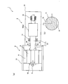
- FIG. 1A is a schematic side sectional view showing a screw compressor 1 according to the first embodiment of the present invention.
- FIG. 1B is a cross-sectional view taken along line AA in FIG.
- the screw compressor 1 is a screw compressor having an electric motor direct connection structure, and includes a screw main body portion 2 and a motor portion 8 (motor).
- the screw main body 2 accommodates a pair of male and female screw rotors 4, a screw shaft 3 that is coaxial with the male rotor 4 a of the screw rotor 4 and integrated with the male rotor 4 a, and the screw rotor 4 and the screw shaft 3.
- the screw shaft 3 is supported at both ends by a bearing 14 and a bearing 15.
- the male rotor 4a and the screw shaft 3 of the screw rotor 4 are manufactured by machining from a single steel material.
- the male rotor 4a and the screw shaft 3 may be manufactured separately and then integrally connected.
- a motor shaft 7 of a motor unit 8 which will be described later, is also manufactured by machining from a single steel material and has an integrated structure with the screw shaft 3.
- the screw shaft 3 and the motor shaft 7 which are integrated with each other constitute a rotating rotor shaft 11.
- the screw shaft 3 and the motor shaft 7 may be manufactured separately and then integrally connected.
- As a method for forming the structure integrally there are flange connection, gear coupling connection, connection using a key (and key groove), shrink fitting, and the like.
- the screw shaft 3 and the motor shaft 7 are coaxial.
- the rotor shaft 11 is an example of a rotor shaft in the present invention that is coaxial with the male rotor of the screw rotor and is integrated with the male rotor.
- the motor unit 8 (motor) is a driving source for rotating the rotor shaft 11, and is disposed on the outer periphery of the rotor 5 fixed to the outer periphery of the motor shaft 7 portion of the rotor shaft 11. And a motor casing 13 that accommodates the rotor 5 and the stator 6.
- a ring-shaped end member 10 is fixed to the end face of the rotor 5.
- the end member 10 is disposed coaxially with the motor shaft 7.
- a bolt 9 is fixed to the end surface of the motor shaft 7 coaxially with the motor shaft 7.
- a bolt 9 is inserted into a hole formed at the center of the end member 10, and the end member 10 is fixed by the bolt 9 or the like.
- the motor shaft 7 (motor) is cantilevered by a bearing 14 (and a bearing 15) on the screw rotor 4 side.
- the bearing 14 supports a portion of the rotor shaft 11 between the screw rotor 4 (male rotor 4a) and the motor unit 8 (motor). A portion of the rotor shaft 11 between the bearing 14 and the rotor 5 of the motor is provided with a notch 16 having a crescent shape as viewed from the axial direction.
- the rotor shaft 11 has a notch 16 provided over a predetermined length in the axial direction.
- the notch 16 makes the bending rigidity of the portion of the rotor shaft 11 between the bearing 14 and the motor rotor 5 different in the two orthogonal directions of the rotor shaft 11.
- “Two orthogonal directions perpendicular to each other of the rotor shaft 11” means, for example, the x-axis direction and the y-axis direction shown in FIG.
- two notches 16 are provided on the outer peripheral surface of the rotor shaft 11 having a circular cross section with a phase difference of 180 °.
- the shapes and dimensions of the two notches 16 are the same. Due to these notches 16, the cross section of the rotor shaft 11 becomes asymmetric in the direction perpendicular to the axis.
- the bending rigidity in the y-axis direction of the portion between the bearing 14 and the motor rotor 5 is smaller than the bending rigidity in the x-axis direction. That is, the bending stiffness differs between the x-axis direction and the y-axis direction.
- the section of the rotor shaft 11 between the bearing 14 and the rotor 5 of the motor is asymmetrical in the direction perpendicular to the axis, so that the bending rigidity of the portion is 2 of the shaft.
- Different in two orthogonal directions x-axis direction and y-axis direction shown in FIG. 1B). By doing so, the natural frequencies of these two orthogonal directions of the rotor shaft 11 change, and the resonance frequency shifts.
- the notch 16 is provided in the portion of the rotor shaft 11 between the bearing 14 and the rotor 5 of the motor, so that the two orthogonal portions of the rotor shaft 11 are orthogonal to each other.
- the bending rigidity of the portion is made different in the direction (x-axis direction, y-axis direction).
- the resonance frequency of the rotor shaft 11 in the direction perpendicular to the axis shifts, and the orbit of the swing of the rotor shaft 11 (cantilever motor shaft 7 portion) becomes an ellipse.
- This makes it difficult for the magnetic attractive force acting between the rotor 5 and the stator 6 of the motor to continuously act as a constant force.
- an increase in the whirling vibration of the rotor shaft 11 can be suppressed.
- the notch portion 16 includes the bearing 14 of the rotor shaft 11 and the rotor 5 of the motor. It may be provided in any part between. The same applies to other embodiments described later. The shape and dimensions of the notch 16 are also determined as appropriate. Of the rotor shaft 11, a notch portion 16 may be provided from end to end in a portion between the bearing 14 and the motor rotor 5, or a notch portion 16 may be provided in part. Also good.
- the notch portion 16 is formed in the rotor shaft 11 (the portion of the motor shaft 7) in the inner portion of the rotor 5 and the rotor shaft 11 (the portion of the screw shaft 3) in the portion between the bearing 14 and the bearing 15.
- the trajectory around the swing of the rotor shaft 11 remains circular. Accordingly, the trajectory does not become an ellipse, and an increase in the whirling vibration of the rotor shaft 11 cannot be suppressed.
- two notches 16 are provided on the outer peripheral surface of the rotor shaft 11 with a phase difference of 180 °.
- an unbalanced force (unbalance force) during rotation of the rotor shaft 11 can be made difficult to occur.
- the notch part 16 may be provided only in one side instead of both sides.
- the number of the notch parts 16 is not limited to two.
- the method of providing the notch 16 in the rotor shaft 11 has an advantage that it is easy to manufacture the rotor shaft 11 having different bending rigidity in the direction perpendicular to the axis. There is also an advantage that it is easy to apply to existing screw compressors.
- FIG. 2A is a schematic side sectional view showing a screw compressor 102 according to the second embodiment of the present invention.
- FIG. 2B is a cross-sectional view taken along the line BB in FIG. 2A and 2B, the same reference numerals are given to the same members as those of the screw compressor 1 of the first embodiment.
- the difference between the screw compressor 1 of the first embodiment and the screw compressor 102 of the present embodiment is that, in the screw compressor 102 of the present embodiment, the two notches 16 are more rigid than the rotor shaft 11 ( It is filled with the material 17 with low bending rigidity). As a result, a portion of the rotor shaft 11 between the bearing 14 and the rotor 5 has a circular cross section from end to end. Since the rotor shaft 11 is made of steel, the material 17 is, for example, a resin material.
- the portion of the rotor shaft 11 between the bearing 14 and the rotor 5 is kept circular in cross section, so that, for example, a ring-shaped component can be easily attached to the portion. Moreover, a ring-shaped component can be firmly attached to the part. As a result, an unbalanced force (unbalance force) at the time of rotation of the rotor shaft 11 due to the ring-shaped component can be made difficult to occur.
- the material 17 may be provided only on one side, not on both sides.
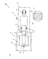
- FIG. 3A is a schematic side sectional view showing a screw compressor 103 according to the third embodiment of the present invention.
- FIG. 3B is a cross-sectional view taken along the line CC of FIG. 3A and 3B, the same reference numerals are given to the same members as those of the screw compressor 1 of the first embodiment.
- the difference between the screw compressor 1 of the first embodiment and the screw compressor 103 of the present embodiment is that the screw compressor 103 of the present embodiment has a difference between the bearing 14 of the rotor shaft 11 and the rotor 5. In this portion, not the notch portion 16 but the through hole 18 is provided. By providing the through hole 18, the bending rigidity of the portion is made different in two orthogonal directions orthogonal to each other of the rotor shaft 11.
- the orbit around the swing of the rotor shaft 11 becomes an ellipse. This makes it difficult for the magnetic attractive force acting between the rotor 5 and the stator 6 of the motor to continuously act as a constant force. As a result, an increase in the whirling vibration of the rotor shaft 11 can be suppressed.
- the method of providing the through hole 18 in the rotor shaft 11 has an advantage that it is easy to manufacture the rotor shaft 11 having different bending rigidity in the direction perpendicular to the axis. There is also an advantage that it is easy to apply to existing screw compressors.
- the through hole 18 passes through the center O in the axial section of the rotor shaft 11 in a direction orthogonal to the axial direction of the rotor shaft 11, and thus unbalanced when the rotor shaft 11 rotates. Force (unbalance force) can be made difficult to occur.
- a hole with a bottom may be provided instead of a hole penetrating the rotor shaft 11.
- the through-hole 18 may be provided with two or more instead of only one.
- the through hole 18 and the bottomed hole may be filled with a material 17 having rigidity lower than that of the rotor shaft 11.
- the angle of the through hole 18 with respect to the axial direction of the rotor shaft 11 is not limited to the angle of the present embodiment.
- FIG. 4A is a schematic side sectional view showing a screw compressor 104 according to the fourth embodiment of the present invention.
- FIG. 4B is a DD cross-sectional view of FIG. 4 (a) and 4 (b), members similar to those of the screw compressor 1 of the first embodiment are denoted by the same reference numerals.
- the difference between the screw compressor 1 of the first embodiment and the screw compressor 104 of the present embodiment is that the screw compressor 104 of the present embodiment has a difference between the bearing 14 of the rotor shaft 11 and the rotor 5.
- the notch 16 is not provided in this part, and the cross section of the part is an ellipse.
- the elliptical portion 19 is shown in FIG. By doing so, the bending rigidity of the portion is made different in two orthogonal directions of the rotor shaft 11 orthogonal to each other.
- the elliptical portion 19 is provided over a predetermined length in the axial direction of the rotor shaft 11.
- a portion of the rotor shaft 11 between the bearing 14 and the motor rotor 5 may be an elliptical portion 19 from end to end, or may be an elliptical portion 19 only in part. Also good. Further, the concave portion generated by providing the oval shape portion 19 may be filled with a material 17 having rigidity lower than that of the rotor shaft 11 as in FIG.
- the orbit around the swing of the rotor shaft 11 becomes an ellipse. This makes it difficult for the magnetic attractive force acting between the rotor 5 and the stator 6 of the motor to continuously act as a constant force. As a result, an increase in the whirling vibration of the rotor shaft 11 can be suppressed.
- FIG. 5A is a schematic side sectional view showing a screw compressor 105 according to the fifth embodiment of the present invention.
- FIG. 5B is a cross-sectional view taken along the line EE of FIG. 5 (a) and 5 (b), members similar to those of the screw compressor 1 of the first embodiment are denoted by the same reference numerals.
- the difference between the screw compressor 1 of the first embodiment and the screw compressor 105 of the present embodiment is that the screw compressor 105 of the present embodiment has a difference between the bearing 14 of the rotor shaft 11 and the rotor 5.
- the notch 16 is not provided in this part, and the cross section of the part is rectangular.
- the rectangular part 20 is shown in FIG. By doing so, the bending rigidity of the portion is made different in two orthogonal directions orthogonal to each other of the rotor shaft 11.
- the rectangular portion 20 is provided over a predetermined length in the axial direction of the rotor shaft 11.
- a portion of the rotor shaft 11 between the bearing 14 and the motor rotor 5 may be a rectangular portion 20 from end to end, or may be a rectangular portion 20 only in part. Also good.
- the concave portion generated by providing the rectangular portion 20 may be filled with a material 17 having rigidity lower than that of the rotor shaft 11 as in FIG.
- the cross section of the portion of the rotor shaft 11 between the bearing 14 and the rotor 5 may be a trapezoidal shape or an asymmetric cross section composed of a plurality of straight lines.
- the orbit around the swing of the rotor shaft 11 becomes an ellipse. This makes it difficult for the magnetic attractive force acting between the rotor 5 and the stator 6 of the motor to continuously act as a constant force. As a result, an increase in the whirling vibration of the rotor shaft 11 can be suppressed.
- Screw compressor 2 Screw body part 3: Screw shaft 4: Screw rotor 4a: Male rotor 5: Rotor 6: Stator 7: Motor shaft 8: Motor part (motor) 9: Bolt 10: End member 11: Rotor shaft 12: Screw casing 13: Motor casing 14, 15: Bearing 16: Notch
Landscapes
- Engineering & Computer Science (AREA)
- Mechanical Engineering (AREA)
- General Engineering & Computer Science (AREA)
- Applications Or Details Of Rotary Compressors (AREA)
- Connection Of Motors, Electrical Generators, Mechanical Devices, And The Like (AREA)
Abstract
スクリュ圧縮機1は、スクリュロータ4と、スクリュロータ4の雄ロータ4aと同軸で当該雄ロータ4aに対して一体構造にされたロータ軸11と、ロータ軸11を回転させるモータ部8(モータ)と、ロータ軸11のうちのスクリュロータ4とモータとの間の部分を支持することでモータを片持ち支持する軸受14と、を備える。切り欠き部16が設けられることにより、ロータ軸11のうちの軸受14とモータの回転子5との間の部分の曲げ剛性は、ロータ軸11の相互に直交する2つの直交方向(x軸方向、y軸方向)で異なっている。
Description
本発明はスクリュ式の圧縮機に関する。
電動機直結構造のスクリュ圧縮機は、駆動ベルトを介する動力伝達方式のスクリュ圧縮機より、エネルギー変換効率に優れる。また、インバータを用いた回転数制御方式を採用するスクリュ圧縮機においては、電動機直結構造のスクリュ圧縮機が主流となっている。コスト低減・機械的損失削減の観点から、電動機直結構造のスクリュ圧縮機は、モータ軸の片側に軸受を設けない片持ち方式のスクリュ圧縮機として構成されることが多い。
ここで、片持ち方式の電動機直結型スクリュ圧縮機は、質量の大きなモータを片持ち支持するため、ロータ軸の曲げ剛性を大きくすることが難しい。このため、片持ち方式の電動機直結型スクリュ圧縮機には、回転時の駆動系・モータの電磁力に起因した加振力による共振、回転軸固有の不安定現象などにより、ロータ軸の振れ回り振動が大きくなりやすいという問題がある。
ロータ軸の振れ回り振動を低減する技術として、例えば特許文献1に記載の技術がある。特許文献1では、モータ軸の端部において、モータ軸と同軸に棒状部材が固定され、この棒状部材に環状の複数の錘が緩やかに挿入されている。ロータ軸の振れ回り振動に対して、軸方向前後のストロークエンドと錘とを、および錘同士とを軸方向で衝突させることにより、振動エネルギーが消散され、ロータ軸の振れ回り振動の増大が抑制される。
特許文献1に記載の技術は、錘の軸方向衝突で振動エネルギーを消散させることでロータ軸の振れ回り振動の増大を抑制するものである。本発明者らは、このたび、これとは別の新たな方法で、ロータ軸の振れ回り振動を低減することを検討した。
本発明は、上記実情に鑑みてなされたものであって、その目的は、錘の軸方向衝突で振動エネルギーを消散させる方法とは別の方法を用いることにより、ロータ軸の振れ回り振動の増大を抑制できる、片持ち方式の電動機直結型スクリュ圧縮機を提供することである。
本発明者らは、前記課題を解決すべく鋭意検討した結果、モータの回転子と固定子との間に作用する磁気吸引力に着目した。そして、本発明者らは、ロータ軸のうちのスクリュロータとモータとの間の部分を支持する軸受とモータの回転子との間の部分の曲げ剛性を、ロータ軸の相互に直交する2つの直交方向で異ならせることを考案した。これにより、ロータ軸の振れ回りの軌道が楕円となり、これにより前記課題を解決できることを、本発明者らは見出した。
すなわち、本発明は、スクリュロータと、前記スクリュロータの雄ロータと同軸で当該雄ロータに対して一体構造にされたロータ軸と、前記ロータ軸を回転させるモータと、前記ロータ軸のうちの前記スクリュロータと前記モータとの間の部分を支持することで前記モータを片持ち支持する軸受と、を備えるスクリュ圧縮機である。前記モータは、前記ロータ軸のモータ軸部分の外周に固定された回転子と、前記回転子の外側に配置された固定子と、を具備してなる。前記ロータ軸のうちの前記軸受と前記回転子との間の部分の曲げ剛性が、当該ロータ軸の相互に直交する2つの直交方向で異なっていることを特徴とする。
本発明によれば、ロータ軸の振れ回りの軌道が楕円となる。これにより、モータの回転子と固定子との間に作用する磁気吸引力が連続的に一定の力として作用しにくくなり、その結果、ロータ軸の振れ回り振動の増大を抑制できる。
以下、本発明を実施するための形態について図面を参照しつつ説明する。
(第1実施形態)
図1(a)は、本発明の第1実施形態に係るスクリュ圧縮機1を示す側断面模式図である。図1(b)は、図1(a)のA-A断面図である。
図1(a)は、本発明の第1実施形態に係るスクリュ圧縮機1を示す側断面模式図である。図1(b)は、図1(a)のA-A断面図である。
(スクリュ圧縮機の構成)
図1に示すように、スクリュ圧縮機1は、電動機直結構造のスクリュ圧縮機であり、スクリュ本体部2とモータ部8(モータ)とを備える。
図1に示すように、スクリュ圧縮機1は、電動機直結構造のスクリュ圧縮機であり、スクリュ本体部2とモータ部8(モータ)とを備える。
(スクリュ本体部)
スクリュ本体部2は、雌雄一対のスクリュロータ4と、スクリュロータ4の雄ロータ4aと同軸で雄ロータ4aに対して一体構造にされたスクリュ軸3と、スクリュロータ4およびスクリュ軸3を収容するスクリュケーシング12と、を有する。スクリュ軸3は、軸受14および軸受15で両持ち支持されている。
スクリュ本体部2は、雌雄一対のスクリュロータ4と、スクリュロータ4の雄ロータ4aと同軸で雄ロータ4aに対して一体構造にされたスクリュ軸3と、スクリュロータ4およびスクリュ軸3を収容するスクリュケーシング12と、を有する。スクリュ軸3は、軸受14および軸受15で両持ち支持されている。
スクリュロータ4の雄ロータ4aとスクリュ軸3とは、1本の鋼材からの削り出し加工などで製作される。なお、雄ロータ4aとスクリュ軸3とは、それぞれ別に製作された後、一体に連結されてもよい。
また、後述するモータ部8(モータ)のモータ軸7も、1本の鋼材からの削り出し加工などで製作されて、スクリュ軸3と一体構造となっている。相互に一体構造にされたスクリュ軸3とモータ軸7とにより、回転するロータ軸11が構成される。なお、スクリュ軸3とモータ軸7とは、それぞれ別に製作された後、一体に連結されてもよい。一体構造化する方法としては、フランジ連結・ギアカップリング連結・キー(およびキー溝)を用いた連結・焼きばめなどがある。スクリュ軸3とモータ軸7とは同軸である。このロータ軸11は、スクリュロータの雄ロータと同軸であり、雄ロータに対して一体構造にされた本発明におけるロータ軸の一例である。
(モータ部)
モータ部8(モータ)は、ロータ軸11を回転させるための駆動源であって、ロータ軸11のモータ軸7の部分の外周に固定された回転子5と、回転子5の外側に配置された固定子6と、回転子5および固定子6を収容するモータケーシング13と、を有する。
モータ部8(モータ)は、ロータ軸11を回転させるための駆動源であって、ロータ軸11のモータ軸7の部分の外周に固定された回転子5と、回転子5の外側に配置された固定子6と、回転子5および固定子6を収容するモータケーシング13と、を有する。
回転子5の端面には、リング状のエンド部材10が固定されている。エンド部材10は、モータ軸7と同軸に配置される。モータ軸7の端面には、モータ軸7と同軸に、ボルト9が固定されている。エンド部材10の中心に形成された孔にボルト9が挿入され、エンド部材10はボルト9などにより固定される。
モータ軸7(モータ)は、スクリュロータ4側の軸受14(および軸受15)で片持ち支持されている。
(ロータ軸に設けられた切り欠き部)
軸受14は、ロータ軸11のうちのスクリュロータ4(雄ロータ4a)とモータ部8(モータ)との間の部分を支持する。この軸受14とモータの回転子5との間のロータ軸11の部分には、軸方向から見て三日月形状をした切り欠き部16が設けられている。
軸受14は、ロータ軸11のうちのスクリュロータ4(雄ロータ4a)とモータ部8(モータ)との間の部分を支持する。この軸受14とモータの回転子5との間のロータ軸11の部分には、軸方向から見て三日月形状をした切り欠き部16が設けられている。
ロータ軸11は、軸方向に所定の長さにわたって設けられた切り欠き部16を有する。切り欠き部16によって、ロータ軸11の、軸受14とモータの回転子5との間の部分の曲げ剛性が、当該ロータ軸11の相互に直交する2つの直交方向で異なるものとなる。「ロータ軸11の相互に直交する2つの直交方向」は、例えば、図1(b)に示したx軸方向、y軸方向のことをいう。
図1(b)に示すように、本実施形態では、切り欠き部16は、円形断面のロータ軸11の外周面に、180°の位相差で、2箇所設けられている。2箇所の切り欠き部16の形状・寸法は同じとされている。これら切り欠き部16により、ロータ軸11の断面が軸直交方向で非対称となる。これにより、軸受14とモータの回転子5との間の部分のy軸方向の曲げ剛性は、x軸方向の曲げ剛性よりも小さくなる。すなわち、x軸方向とy軸方向とで曲げ剛性が異なるようになる。
(数値解析結果)
前記したように、本実施形態では、軸受14とモータの回転子5との間における、ロータ軸11の部分の断面を軸直交方向で非対称とすることで、当該部分の曲げ剛性を軸の2つの直交方向(図1(b)に示すx軸方向、y軸方向)で異ならせている。こうすることで、ロータ軸11のこれら2つの直交方向の固有振動数が変化し、共振周波数がずれる。一例として、電動機直結型スクリュ圧縮機において、軸受14とモータの回転子5との間における、ロータ軸11の部分の軸直交方向の曲げ剛性を異ならせたことによる、ロータ軸11の振れ回り振動の安定性について解析した。この動機直結型スクリュ圧縮機は、モータ容量:7.5kWの電動機を搭載しており、モータ軸片持ち方式である。表1は解析結果を示す。表1より、軸受14とモータの回転子5との間のロータ軸11部分の軸直交方向の曲げ剛性を異ならせることで、ロータ軸11の振れ回り振動の増大を抑制できることがわかる。
前記したように、本実施形態では、軸受14とモータの回転子5との間における、ロータ軸11の部分の断面を軸直交方向で非対称とすることで、当該部分の曲げ剛性を軸の2つの直交方向(図1(b)に示すx軸方向、y軸方向)で異ならせている。こうすることで、ロータ軸11のこれら2つの直交方向の固有振動数が変化し、共振周波数がずれる。一例として、電動機直結型スクリュ圧縮機において、軸受14とモータの回転子5との間における、ロータ軸11の部分の軸直交方向の曲げ剛性を異ならせたことによる、ロータ軸11の振れ回り振動の安定性について解析した。この動機直結型スクリュ圧縮機は、モータ容量:7.5kWの電動機を搭載しており、モータ軸片持ち方式である。表1は解析結果を示す。表1より、軸受14とモータの回転子5との間のロータ軸11部分の軸直交方向の曲げ剛性を異ならせることで、ロータ軸11の振れ回り振動の増大を抑制できることがわかる。

(作用効果)
本実施形態のスクリュ圧縮機1では、ロータ軸11のうちの軸受14とモータの回転子5との間の部分に切り欠き部16を設けることで、ロータ軸11の相互に直交する2つの直交方向(x軸方向、y軸方向)で当該部分の曲げ剛性を異ならせている。これにより、ロータ軸11の軸直交方向の共振周波数がずれ、ロータ軸11(片持ちのモータ軸7部分)の振れ回りの軌道が楕円となる。これにより、モータの回転子5と固定子6との間に作用する磁気吸引力が連続的に一定の力として相互に作用しにくくなる。その結果、ロータ軸11の振れ回り振動の増大を抑制することができる。
本実施形態のスクリュ圧縮機1では、ロータ軸11のうちの軸受14とモータの回転子5との間の部分に切り欠き部16を設けることで、ロータ軸11の相互に直交する2つの直交方向(x軸方向、y軸方向)で当該部分の曲げ剛性を異ならせている。これにより、ロータ軸11の軸直交方向の共振周波数がずれ、ロータ軸11(片持ちのモータ軸7部分)の振れ回りの軌道が楕円となる。これにより、モータの回転子5と固定子6との間に作用する磁気吸引力が連続的に一定の力として相互に作用しにくくなる。その結果、ロータ軸11の振れ回り振動の増大を抑制することができる。
ここで、モータ容量・ロータ軸のサイズなどから得られる振れ回り振動の増大を抑制できる剛性比が満たされる限り、切り欠き部16は、ロータ軸11のうちの軸受14とモータの回転子5との間のどの部分に設けられていてもよい。これは、後述する他の実施形態においても同様である。切り欠き部16の形状・寸法についても適宜決定される。ロータ軸11のうち、軸受14とモータの回転子5との間の部分において、端から端まで切り欠き部16が設けられていてもよいし、一部に切り欠き部16が設けられていてもよい。
なお、例えば、回転子5の内側部分のロータ軸11(モータ軸7の部分)、軸受14と軸受15との間の部分のロータ軸11(スクリュ軸3の部分)に、切り欠き部16を設けた場合、ロータ軸11(片持ちのモータ軸7部分)の振れ回りの軌道は円形のままである。したがって、軌道が楕円とはならず、ロータ軸11の振れ回り振動の増大を抑制することはできない。
本実施形態では、ロータ軸11の外周面に、180°の位相差で、2箇所の切り欠き部16が設けられている。これにより、ロータ軸11の回転時の不釣り合い力(アンバランス力)を生じにくくすることができる。なお、回転時の不釣り合い力が影響しない場合、切り欠き部16は、両側ではなく、片側のみに設けられてもよい。また、切り欠き部16の数は2つに限定されない。
ロータ軸11に切り欠き部16を設ける方法には、軸直交方向で曲げ剛性が異なる当該ロータ軸11を製作し易いというメリットがある。また、既存のスクリュ圧縮機に適用し易いというメリットもある。
(第2実施形態)
図2(a)は、本発明の第2実施形態に係るスクリュ圧縮機102を示す側断面模式図である。図2(b)は、図2(a)のB-B断面図である。図2(a)(b)において、第1実施形態のスクリュ圧縮機1と同様の部材については同一の符号が付されている。
図2(a)は、本発明の第2実施形態に係るスクリュ圧縮機102を示す側断面模式図である。図2(b)は、図2(a)のB-B断面図である。図2(a)(b)において、第1実施形態のスクリュ圧縮機1と同様の部材については同一の符号が付されている。
第1実施形態のスクリュ圧縮機1と、本実施形態のスクリュ圧縮機102との相違点は、本実施形態のスクリュ圧縮機102では、2つの切り欠き部16が、ロータ軸11よりも剛性(曲げ剛性)の低い素材17でそれぞれ埋められていることである。これにより、ロータ軸11のうちの軸受14と回転子5との間の部分は、端から端まで断面円形となる。ロータ軸11は鋼材からなるので、素材17は例えば樹脂系材料である。
(作用効果)
本実施形態によると、ロータ軸11のうちの軸受14と回転子5との間の部分が断面円形に保たれるので、例えば、当該部分にリング状部品を容易に取り付けることができる。また、当該部分にリング状部品を強固に取り付けることができる。結果として、リング状部品に起因するロータ軸11の回転時の不釣り合い力(アンバランス力)を生じにくくすることができる。
本実施形態によると、ロータ軸11のうちの軸受14と回転子5との間の部分が断面円形に保たれるので、例えば、当該部分にリング状部品を容易に取り付けることができる。また、当該部分にリング状部品を強固に取り付けることができる。結果として、リング状部品に起因するロータ軸11の回転時の不釣り合い力(アンバランス力)を生じにくくすることができる。
なお、素材17に起因する回転時の不釣り合い力が影響しない場合、素材17は両側ではなく片側のみに設けられてもよい。
(第3実施形態)
図3(a)は、本発明の第3実施形態に係るスクリュ圧縮機103を示す側断面模式図である。図3(b)は、図3(a)のC-C断面図である。図3(a)(b)において、第1実施形態のスクリュ圧縮機1と同様の部材については同一の符号が付されている。
図3(a)は、本発明の第3実施形態に係るスクリュ圧縮機103を示す側断面模式図である。図3(b)は、図3(a)のC-C断面図である。図3(a)(b)において、第1実施形態のスクリュ圧縮機1と同様の部材については同一の符号が付されている。
第1実施形態のスクリュ圧縮機1と、本実施形態のスクリュ圧縮機103との相違点は、本実施形態のスクリュ圧縮機103では、ロータ軸11のうちの軸受14と回転子5との間の部分に、切り欠き部16ではなく貫通孔18が設けられていることである。貫通孔18を設けることにより、ロータ軸11の相互に直交する2つの直交方向で当該部分の曲げ剛性を異ならせている。
(作用効果)
本実施形態によっても、第1実施形態と同様に、ロータ軸11(片持ちのモータ軸7部分)の振れ回りの軌道が楕円となる。これにより、モータの回転子5と固定子6との間に作用する磁気吸引力が連続的に一定の力として相互に作用しにくくなる。その結果、ロータ軸11の振れ回り振動の増大を抑制することができる。
本実施形態によっても、第1実施形態と同様に、ロータ軸11(片持ちのモータ軸7部分)の振れ回りの軌道が楕円となる。これにより、モータの回転子5と固定子6との間に作用する磁気吸引力が連続的に一定の力として相互に作用しにくくなる。その結果、ロータ軸11の振れ回り振動の増大を抑制することができる。
また、ロータ軸11に貫通孔18を設ける方法には、軸直交方向で曲げ剛性が異なる当該ロータ軸11を製作し易いというメリットがある。また、既存のスクリュ圧縮機に適用し易いというメリットもある。
さらに、本実施形態では、貫通孔18が、ロータ軸11の軸方向断面における中心Oを、ロータ軸11の軸方向に対して直交する向きで貫通するので、ロータ軸11の回転時の不釣り合い力(アンバランス力)を生じにくくすることができる。
なお、ロータ軸11を貫通する孔ではなく、有底の穴が設けられてもよい。また、貫通孔18は、1本だけではなく複数本設けられていてもよい。また、貫通孔18や有底の穴は、ロータ軸11よりも剛性の低い素材17で埋められてもよい。さらには、ロータ軸11の軸方向に対する貫通孔18の角度は、本実施形態の角度に限定されない。
(第4実施形態)
図4(a)は、本発明の第4実施形態に係るスクリュ圧縮機104を示す側断面模式図である。図4(b)は、図4(a)のD-D断面図である。図4(a)(b)において、第1実施形態のスクリュ圧縮機1と同様の部材については同一の符号が付されている。
図4(a)は、本発明の第4実施形態に係るスクリュ圧縮機104を示す側断面模式図である。図4(b)は、図4(a)のD-D断面図である。図4(a)(b)において、第1実施形態のスクリュ圧縮機1と同様の部材については同一の符号が付されている。
第1実施形態のスクリュ圧縮機1と、本実施形態のスクリュ圧縮機104との相違点は、本実施形態のスクリュ圧縮機104では、ロータ軸11のうちの軸受14と回転子5との間の部分に切り欠き部16が設けられず、当該部分の断面を楕円としていることである。楕円形状部19は図4(b)に示されている。こうすることで、ロータ軸11の、相互に直交する2つの直交方向で、当該部分の曲げ剛性を異ならせている。楕円形状部19は、ロータ軸11の軸方向において所定の長さにわたって設けられている。
なお、ロータ軸11のうちの軸受14とモータの回転子5との間の部分は、端から端まで楕円形状部19とされていてもよいし、一部分のみにおいて楕円形状部19とされていてもよい。また、楕円形状部19を設けたことにより生じる凹部は、図2(b)と同じように、ロータ軸11よりも剛性の低い素材17で埋められてもよい。
(作用効果)
本実施形態によっても第1実施形態と同様に、ロータ軸11(片持ちのモータ軸7部分)の振れ回りの軌道が楕円となる。これにより、モータの回転子5と固定子6との間に作用する磁気吸引力が連続的に一定の力として相互に作用しにくくなる。その結果、ロータ軸11の振れ回り振動の増大を抑制することができる。
本実施形態によっても第1実施形態と同様に、ロータ軸11(片持ちのモータ軸7部分)の振れ回りの軌道が楕円となる。これにより、モータの回転子5と固定子6との間に作用する磁気吸引力が連続的に一定の力として相互に作用しにくくなる。その結果、ロータ軸11の振れ回り振動の増大を抑制することができる。
(第5実施形態)
図5(a)は、本発明の第5実施形態に係るスクリュ圧縮機105を示す側断面模式図である。図5(b)は、図5(a)のE-E断面図である。図5(a)(b)において、第1実施形態のスクリュ圧縮機1と同様の部材については同一の符号が付されている。
図5(a)は、本発明の第5実施形態に係るスクリュ圧縮機105を示す側断面模式図である。図5(b)は、図5(a)のE-E断面図である。図5(a)(b)において、第1実施形態のスクリュ圧縮機1と同様の部材については同一の符号が付されている。
第1実施形態のスクリュ圧縮機1と、本実施形態のスクリュ圧縮機105との相違点は、本実施形態のスクリュ圧縮機105では、ロータ軸11のうちの軸受14と回転子5との間の部分に切り欠き部16が設けられず、当該部分の断面を長方形としていることである。長方形状部20は図5に示されている。こうすることで、ロータ軸11の相互に直交する2つの直交方向で当該部分の曲げ剛性を異ならせている。長方形状部20は、ロータ軸11の軸方向において、所定の長さにわたって設けられている。
なお、ロータ軸11のうちの軸受14とモータの回転子5との間の部分は、端から端まで長方形状部20とされていてもよいし、一部分のみにおいて長方形状部20とされていてもよい。また、長方形状部20を設けたことにより生じる凹部は、図2(b)と同じように、ロータ軸11よりも剛性の低い素材17で埋められてもよい。
また、所要の剛性の異方性を満たす限り、ロータ軸11の、軸受14と回転子5との間の部分の断面が、台形もしくは複数の直線で構成される非対称断面とされてもよい。
また、所要の剛性の異方性を満たす限り、ロータ軸11の、軸受14と回転子5との間の部分の断面が、台形もしくは複数の直線で構成される非対称断面とされてもよい。
(作用効果)
本実施形態によっても第1実施形態と同様に、ロータ軸11(片持ちのモータ軸7部分)の振れ回りの軌道が楕円となる。これにより、モータの回転子5と固定子6との間に作用する磁気吸引力が連続的に一定の力として相互に作用しにくくなる。その結果、ロータ軸11の振れ回り振動の増大を抑制することができる。
本実施形態によっても第1実施形態と同様に、ロータ軸11(片持ちのモータ軸7部分)の振れ回りの軌道が楕円となる。これにより、モータの回転子5と固定子6との間に作用する磁気吸引力が連続的に一定の力として相互に作用しにくくなる。その結果、ロータ軸11の振れ回り振動の増大を抑制することができる。
以上、本発明の実施形態について説明したが、本発明は上述の実施の形態に限られるものではなく、特許請求の範囲に記載した限りにおいて様々に変更して実施することが可能なものである。本出願は2012年6月14日出願の日本特許出願(特願2012-135038)に基づくものであり、その内容はここに参照として取り込まれる。
1:スクリュ圧縮機
2:スクリュ本体部
3:スクリュ軸
4:スクリュロータ
4a:雄ロータ
5:回転子
6:固定子
7:モータ軸
8:モータ部(モータ)
9:ボルト
10:エンド部材
11:ロータ軸
12:スクリュケーシング
13:モータケーシング
14、15:軸受
16:切り欠き部
2:スクリュ本体部
3:スクリュ軸
4:スクリュロータ
4a:雄ロータ
5:回転子
6:固定子
7:モータ軸
8:モータ部(モータ)
9:ボルト
10:エンド部材
11:ロータ軸
12:スクリュケーシング
13:モータケーシング
14、15:軸受
16:切り欠き部
Claims (6)
- スクリュロータと、
前記スクリュロータの雄ロータと同軸であり、前記雄ロータに対して一体構造にされたロータ軸と、
前記ロータ軸を回転させるモータと、
前記ロータ軸の、前記スクリュロータと前記モータとの間の部分を支持することで、前記モータを片持ち支持する軸受と、
を備えるスクリュ圧縮機であって、
前記モータは、
前記ロータ軸のモータ軸部分の外周に固定された回転子と、
前記回転子の外側に配置された固定子と、
を有し、
前記ロータ軸の、前記軸受と前記回転子との間の部分の曲げ剛性が、前記ロータ軸の相互に直交する2つの直交方向で異なることを特徴とする、スクリュ圧縮機。 - 請求項1に記載のスクリュ圧縮機において、
前記ロータ軸の、前記軸受と前記回転子との間の部分に切り欠き部が設けられていることにより、前記軸受と前記回転子との間の部分の曲げ剛性が、前記ロータ軸の相互に直交する2つの直交方向で異なることを特徴とする、スクリュ圧縮機。 - 請求項2に記載のスクリュ圧縮機において、
前記切り欠き部が、前記ロータ軸の素材よりも剛性の低い素材で埋められていることを特徴とする、スクリュ圧縮機。 - 請求項1に記載のスクリュ圧縮機において、
前記ロータ軸の、前記軸受と前記回転子との間の部分に貫通孔または有底の穴が設けられていることにより、前記軸受と前記回転子との間の部分の曲げ剛性が、前記ロータ軸の相互に直交する2つの直交方向で異なることを特徴とする、スクリュ圧縮機。 - 請求項1に記載のスクリュ圧縮機において、
前記ロータ軸の、前記軸受と前記回転子との間の部分の断面が楕円とされていることにより、前記軸受と前記回転子との間の部分の曲げ剛性が、前記ロータ軸の相互に直交する2つの直交方向で異なることを特徴とする、スクリュ圧縮機。 - 請求項1に記載のスクリュ圧縮機において、
前記ロータ軸の、前記軸受と前記回転子との間の部分の断面が長方形とされていることにより、前記軸受と前記回転子との間の部分の曲げ剛性が、前記ロータ軸の相互に直交する2つの直交方向で異なることを特徴とする、スクリュ圧縮機。
Priority Applications (1)
| Application Number | Priority Date | Filing Date | Title |
|---|---|---|---|
| CN201380030833.6A CN104379935B (zh) | 2012-06-14 | 2013-05-17 | 螺旋式压缩机 |
Applications Claiming Priority (2)
| Application Number | Priority Date | Filing Date | Title |
|---|---|---|---|
| JP2012-135038 | 2012-06-14 | ||
| JP2012135038A JP5878432B2 (ja) | 2012-06-14 | 2012-06-14 | スクリュ圧縮機 |
Publications (1)
| Publication Number | Publication Date |
|---|---|
| WO2013187181A1 true WO2013187181A1 (ja) | 2013-12-19 |
Family
ID=49758013
Family Applications (1)
| Application Number | Title | Priority Date | Filing Date |
|---|---|---|---|
| PCT/JP2013/063842 WO2013187181A1 (ja) | 2012-06-14 | 2013-05-17 | スクリュ圧縮機 |
Country Status (3)
| Country | Link |
|---|---|
| JP (1) | JP5878432B2 (ja) |
| CN (1) | CN104379935B (ja) |
| WO (1) | WO2013187181A1 (ja) |
Families Citing this family (1)
| Publication number | Priority date | Publication date | Assignee | Title |
|---|---|---|---|---|
| CN107191378B (zh) * | 2017-06-30 | 2019-07-05 | 阿特拉斯·科普柯(无锡)压缩机有限公司 | 压缩机与电机的连接结构 |
Citations (4)
| Publication number | Priority date | Publication date | Assignee | Title |
|---|---|---|---|---|
| JPH01130093U (ja) * | 1988-02-29 | 1989-09-05 | ||
| JP2001227489A (ja) * | 2000-02-14 | 2001-08-24 | Kobe Steel Ltd | 油冷式スクリュ圧縮機 |
| JP2011196369A (ja) * | 2010-02-26 | 2011-10-06 | Kobe Steel Ltd | スクリュ圧縮機 |
| JP2011252402A (ja) * | 2010-05-31 | 2011-12-15 | Kobe Steel Ltd | スクリュ圧縮機 |
Family Cites Families (7)
| Publication number | Priority date | Publication date | Assignee | Title |
|---|---|---|---|---|
| CN1050592A (zh) * | 1989-09-25 | 1991-04-10 | 北京市科学技术开发交流中心 | 内减振旋转式压缩机 |
| JP4120733B2 (ja) * | 1999-03-10 | 2008-07-16 | 三菱電機株式会社 | 二段スクリュー圧縮機 |
| JP2001252402A (ja) * | 2000-03-13 | 2001-09-18 | Heiwa Corp | 遊技制御電力系統装置 |
| US7100743B2 (en) * | 2001-12-17 | 2006-09-05 | Lg Electronics Inc. | Crank shaft in dual capacity compressor |
| TWI274105B (en) * | 2005-01-20 | 2007-02-21 | Hitachi Ltd | Portable vacuum pump and automatic urination treatment apparatus using thereof |
| CN101303017A (zh) * | 2007-05-10 | 2008-11-12 | 乐金电子(天津)电器有限公司 | 空调器压缩机的减振结构 |
| JP4842341B2 (ja) * | 2009-03-23 | 2011-12-21 | 日立オートモティブシステムズ株式会社 | ギヤポンプ及びブレーキ装置用ギヤポンプ |
-
2012
- 2012-06-14 JP JP2012135038A patent/JP5878432B2/ja active Active
-
2013
- 2013-05-17 WO PCT/JP2013/063842 patent/WO2013187181A1/ja active Application Filing
- 2013-05-17 CN CN201380030833.6A patent/CN104379935B/zh active Active
Patent Citations (4)
| Publication number | Priority date | Publication date | Assignee | Title |
|---|---|---|---|---|
| JPH01130093U (ja) * | 1988-02-29 | 1989-09-05 | ||
| JP2001227489A (ja) * | 2000-02-14 | 2001-08-24 | Kobe Steel Ltd | 油冷式スクリュ圧縮機 |
| JP2011196369A (ja) * | 2010-02-26 | 2011-10-06 | Kobe Steel Ltd | スクリュ圧縮機 |
| JP2011252402A (ja) * | 2010-05-31 | 2011-12-15 | Kobe Steel Ltd | スクリュ圧縮機 |
Also Published As
| Publication number | Publication date |
|---|---|
| CN104379935B (zh) | 2016-08-17 |
| CN104379935A (zh) | 2015-02-25 |
| JP2013256927A (ja) | 2013-12-26 |
| JP5878432B2 (ja) | 2016-03-08 |
Similar Documents
| Publication | Publication Date | Title |
|---|---|---|
| US10256708B2 (en) | Electric machine | |
| US9496758B2 (en) | Rotor for rotating electric machine | |
| JP5793077B2 (ja) | ロータ及び回転電気機械 | |
| US9065314B2 (en) | Rotor of buried magnet-type electric motor, motor and machine tool having the rotor | |
| JP6202354B2 (ja) | 磁束集中型ポールピースを有するマグネチックギア | |
| JP2007336671A (ja) | 永久磁石回転電機の回転子 | |
| JP5793078B2 (ja) | T字形磁石ウェッジを備えた回転電気機械用内部ロータ | |
| WO2015097767A1 (ja) | 永久磁石式回転電機 | |
| JP6253520B2 (ja) | 回転電機 | |
| JP2012500612A (ja) | 回転電気機械用の溝付きシャフトを備えた内部ロータ | |
| US10312784B2 (en) | Switched reluctance motor with reduced torque ripple | |
| WO2013187181A1 (ja) | スクリュ圧縮機 | |
| JP2008131783A (ja) | 回転子及び回転機 | |
| JP2002281698A (ja) | 回転電機の固定子およびそれを用いた回転電機 | |
| Kumashiro et al. | Optimization of Stack Length in Magnetic-Geared Motor with Magnetically Suspended High-Speed Rotor | |
| JP4028183B2 (ja) | 回転電機の固定子およびそれを用いた回転電機 | |
| Jaatinen et al. | Comparison of winding arrangements of a high-speed interior permanent magnet bearingless machine | |
| KR20180105901A (ko) | 영구 자석 매립형 회전자, 영구 자석형 모터 및 압축기 | |
| JP6877318B2 (ja) | ギヤモータ | |
| CN105915024A (zh) | 一种高性能场调制磁齿轮 | |
| CN206226199U (zh) | 电机转子组件和具有其的电机 | |
| WO2023042439A1 (ja) | ギヤモータ | |
| TW202011672A (zh) | 籠形轉子及旋轉電機 | |
| CN100383431C (zh) | 质量中心偏离旋转轴线的飞轮 | |
| CN217769644U (zh) | 一种电机转子及驱动电机 |
Legal Events
| Date | Code | Title | Description |
|---|---|---|---|
| 121 | Ep: the epo has been informed by wipo that ep was designated in this application |
Ref document number: 13803741 Country of ref document: EP Kind code of ref document: A1 |
|
| WWE | Wipo information: entry into national phase |
Ref document number: IDP00201407712 Country of ref document: ID |
|
| NENP | Non-entry into the national phase |
Ref country code: DE |
|
| 122 | Ep: pct application non-entry in european phase |
Ref document number: 13803741 Country of ref document: EP Kind code of ref document: A1 |