WO2013183224A1 - Contacteur électromagnétique - Google Patents
Contacteur électromagnétique Download PDFInfo
- Publication number
- WO2013183224A1 WO2013183224A1 PCT/JP2013/002991 JP2013002991W WO2013183224A1 WO 2013183224 A1 WO2013183224 A1 WO 2013183224A1 JP 2013002991 W JP2013002991 W JP 2013002991W WO 2013183224 A1 WO2013183224 A1 WO 2013183224A1
- Authority
- WO
- WIPO (PCT)
- Prior art keywords
- contact
- movable
- movable plunger
- permanent magnet
- plate portion
- Prior art date
Links
Images


Classifications
-
- H—ELECTRICITY
- H01—ELECTRIC ELEMENTS
- H01H—ELECTRIC SWITCHES; RELAYS; SELECTORS; EMERGENCY PROTECTIVE DEVICES
- H01H1/00—Contacts
- H01H1/50—Means for increasing contact pressure, preventing vibration of contacts, holding contacts together after engagement, or biasing contacts to the open position
- H01H1/54—Means for increasing contact pressure, preventing vibration of contacts, holding contacts together after engagement, or biasing contacts to the open position by magnetic force
-
- H—ELECTRICITY
- H01—ELECTRIC ELEMENTS
- H01H—ELECTRIC SWITCHES; RELAYS; SELECTORS; EMERGENCY PROTECTIVE DEVICES
- H01H50/00—Details of electromagnetic relays
- H01H50/16—Magnetic circuit arrangements
- H01H50/163—Details concerning air-gaps, e.g. anti-remanence, damping, anti-corrosion
-
- H—ELECTRICITY
- H01—ELECTRIC ELEMENTS
- H01H—ELECTRIC SWITCHES; RELAYS; SELECTORS; EMERGENCY PROTECTIVE DEVICES
- H01H50/00—Details of electromagnetic relays
- H01H50/16—Magnetic circuit arrangements
- H01H50/36—Stationary parts of magnetic circuit, e.g. yoke
-
- H—ELECTRICITY
- H01—ELECTRIC ELEMENTS
- H01H—ELECTRIC SWITCHES; RELAYS; SELECTORS; EMERGENCY PROTECTIVE DEVICES
- H01H50/00—Details of electromagnetic relays
- H01H50/16—Magnetic circuit arrangements
- H01H50/36—Stationary parts of magnetic circuit, e.g. yoke
- H01H50/42—Auxiliary magnetic circuits, e.g. for maintaining armature in, or returning armature to, position of rest, for damping or accelerating movement
-
- H—ELECTRICITY
- H01—ELECTRIC ELEMENTS
- H01H—ELECTRIC SWITCHES; RELAYS; SELECTORS; EMERGENCY PROTECTIVE DEVICES
- H01H1/00—Contacts
- H01H1/50—Means for increasing contact pressure, preventing vibration of contacts, holding contacts together after engagement, or biasing contacts to the open position
- H01H1/54—Means for increasing contact pressure, preventing vibration of contacts, holding contacts together after engagement, or biasing contacts to the open position by magnetic force
- H01H2001/545—Means for increasing contact pressure, preventing vibration of contacts, holding contacts together after engagement, or biasing contacts to the open position by magnetic force having permanent magnets directly associated with the contacts
-
- H—ELECTRICITY
- H01—ELECTRIC ELEMENTS
- H01H—ELECTRIC SWITCHES; RELAYS; SELECTORS; EMERGENCY PROTECTIVE DEVICES
- H01H50/00—Details of electromagnetic relays
- H01H50/02—Bases; Casings; Covers
- H01H50/023—Details concerning sealing, e.g. sealing casing with resin
- H01H2050/025—Details concerning sealing, e.g. sealing casing with resin containing inert or dielectric gasses, e.g. SF6, for arc prevention or arc extinction
-
- H—ELECTRICITY
- H01—ELECTRIC ELEMENTS
- H01H—ELECTRIC SWITCHES; RELAYS; SELECTORS; EMERGENCY PROTECTIVE DEVICES
- H01H50/00—Details of electromagnetic relays
- H01H50/54—Contact arrangements
- H01H50/546—Contact arrangements for contactors having bridging contacts
Definitions
- the present invention relates to an electromagnetic contactor including a fixed contact, a movable contact that can be contacted and separated from the fixed contact, and an electromagnet unit that drives the movable contact.
- a driving device that drives a movable contact that is arranged so as to be able to contact and separate from a fixed contact, it is movable by a combined attractive force of the attractive force of a permanent magnet and the attractive force of an electromagnetic coil.
- a polarized electromagnet device that drives an iron core portion against the restoring force of a spring, wherein one magnetic pole face of a permanent magnet is brought into contact with two central pieces of a U-shaped fixed iron core, and the other magnetic pole face is
- a polarized electromagnet device that is brought into contact with a central piece of a pair of L-shaped magnetic pole plates arranged outside an electromagnetic coil in a fixed iron core (see, for example, Patent Documents 1 and 2).
- the present invention has been made paying attention to the above-mentioned unsolved problems of the conventional example, and while ensuring a necessary magnetic force with one permanent magnet without using a plurality of permanent magnets, the magnetic force of the permanent magnets is also achieved. It aims at providing the magnetic contactor which can be used efficiently.
- a first aspect of an electromagnetic contactor includes a pair of fixed contacts arranged at a predetermined interval and a pair of fixed contacts that are detachably arranged.
- a movable contact provided, and an electromagnet unit for driving the movable contact.
- the electromagnet unit includes a magnetic yoke that surrounds the plunger drive unit, and a movable end that protrudes through an opening formed in the magnetic yoke, supports the movable contactor via a connecting shaft, and is biased by a return spring.
- a plunger an annular permanent magnet magnetized in a movable direction of the movable plunger fixedly arranged so as to surround a peripheral flange formed on the protruding end side of the movable plunger, and the magnetic yoke of the annular permanent magnet; Is provided on the opposite side and has an auxiliary yoke for restricting the movement of the peripheral flange portion of the movable plunger.
- the auxiliary yoke is formed with a stepped plate portion projecting from the central portion of the flat plate portion and having an opening through which the connecting shaft is inserted.
- the magnetic force of the annular permanent magnet can be applied to the peripheral flange portion of the movable plunger without leakage. Therefore, the magnetic force of the annular permanent magnet can be used efficiently. Further, the urging force of the return spring can be reduced by applying a suction force that moves the movable contact member in the releasing direction to the movable plunger. For this reason, the electromagnet unit can be reduced in size by reducing the magnetomotive force of the exciting coil. Further, in the released state, the peripheral flange portion of the movable plunger can be attracted by the magnetic force of the permanent magnet, and high malfunction resistance performance can be ensured at the time of release.
- the step plate is protruded from the auxiliary yoke with which the peripheral flange of the movable plunger abuts, the rigidity of the auxiliary yoke itself can be increased, and the stroke of the movable plunger can be accurately regulated by preventing deformation of the auxiliary yoke. can do.
- the magnetic force of the annular permanent magnet directly acts on the peripheral flange portion of the movable plunger via the auxiliary yoke, the magnetic flux of the annular permanent magnet can be used more efficiently while suppressing the leakage magnetic flux.
- the auxiliary yoke has a flat plate portion and a step plate portion integrally formed by press molding. According to the second aspect, since the auxiliary yoke is integrally formed by press molding, the auxiliary yoke can be easily manufactured. Moreover, the 3rd aspect of the electromagnetic contactor which concerns on this invention determines the height of the said level
- the peripheral flange portion of the movable plunger can be attracted by one annular permanent magnet, and the cost can be reduced by reducing the number of parts.
- the annular permanent magnet is disposed so as to surround the peripheral flange portion of the movable plunger, the annular permanent magnet can be disposed in the vicinity of the position where the attractive force is applied, and the magnetic force of the annular permanent magnet is efficiently used. be able to. Since the magnetic force of the annular permanent magnet is directly applied to the peripheral flange portion of the movable plunger by the auxiliary yoke, the leakage magnetic flux can be suppressed and the magnetic force of the annular permanent magnet can be used more efficiently. Further, by forming the step plate portion so as to protrude from the auxiliary yoke, the rigidity of the auxiliary yoke itself can be increased and the stroke of the movable plunger can be accurately regulated.
- the attractive force of the annular permanent magnet can be made to act so as to attract the movable plunger in the released state, and the urging force of the return spring that returns the movable plunger to the released state can be suppressed.
- the magnetomotive force of the exciting coil can be reduced, the height of the electromagnet unit can be lowered, and the entire electromagnetic contactor can be reduced in size.
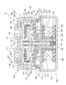
- FIG. 1 is a sectional view showing an example of an electromagnetic switch according to the present invention
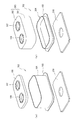
- FIG. 2 is an exploded perspective view of an arc extinguishing chamber.
- reference numeral 10 denotes an electromagnetic contactor.
- the electromagnetic contactor 10 includes a contact device 100 having a contact mechanism and an electromagnet unit 200 that drives the contact device 100.
- the contact device 100 includes an arc extinguishing chamber 102 that houses the contact mechanism 101.
- FIG. 1 is a sectional view showing an example of an electromagnetic switch according to the present invention
- the arc extinguishing chamber 102 has a metal rectangular tube body 104 having a flange portion 103 protruding outward at a metal lower end portion, and the upper end of the metal square tube body 104 is closed. And a fixed contact supporting insulating substrate 105 composed of a flat ceramic insulating substrate.
- the metal rectangular tube 104 is fixed by being sealed and bonded to an upper magnetic yoke 210 of an electromagnet unit 200 whose flange 103 is described later. Further, through holes 106 and 107 through which a pair of fixed contacts 111 and 112 (described later) are inserted are formed in the fixed contact supporting insulating substrate 105 at a central portion with a predetermined interval. A metallization process is applied to positions around the through-holes 106 and 107 on the upper surface side of the fixed contact supporting insulating substrate 105 and a position in contact with the metal rectangular cylinder 104 on the lower surface side.
- a copper foil is formed around the through-holes 106 and 107 and at a position in contact with the metal rectangular cylinder 104 with a plurality of fixed contact support insulating substrates 105 arranged vertically and horizontally on a plane. .
- the contact mechanism 101 includes a pair of fixed contacts 111 and 112 that are inserted into and fixed to the through holes 106 and 107 of the fixed contact support insulating substrate 105 of the arc extinguishing chamber 102.
- Each of the fixed contacts 111 and 112 includes a support conductor portion 114 having a flange portion 113 protruding outward at an upper end inserted through the through holes 106 and 107 of the fixed contact support insulating substrate 105, and the support conductor portion 114.
- a C-shaped portion 115 disposed on the lower surface side of the fixed contact supporting insulating substrate 105 and having an inner side open.
- the C-shaped portion 115 includes an upper plate portion 116 that extends outward along the lower surface of the fixed contact supporting insulating substrate 105, an intermediate plate portion 117 that extends downward from the outer end portion of the upper plate portion 116, and an intermediate portion L formed by the intermediate plate portion 117 and the lower plate portion 118 from the lower end side of the plate portion 117 to the inner side parallel to the upper plate portion 116, that is, the lower plate portion 118 extending in the facing direction of the fixed contacts 111 and 112. It is formed in a C shape by adding an upper plate portion 116 to the shape.
- the support conductor portion 114 and the C-shaped portion 115 include a pin 114 a that protrudes from the lower end surface of the support conductor portion 114 in the through hole 120 formed in the upper plate portion 116 of the C-shaped portion 115. In the inserted state, it is fixed by brazing, for example.
- the fixing of the support conductor 114 and the C-shaped portion 115 is not limited to brazing or the like, but the pin 114a is fitted into the through hole 120, the male screw is formed on the pin 114a, and the female screw is formed on the through hole 120. Then, they may be screwed together.
- an insulating cover 121 made of a synthetic resin material that restricts the generation of an arc is attached to each of the C-shaped portions 115 of the fixed contacts 111 and 112.
- the insulating cover 121 covers the inner peripheral surfaces of the upper plate portion 116 and the intermediate plate portion 117 of the C-shaped portion 115.
- the insulating cover 121 by attaching the insulating cover 121 to the C-shaped portion 115 of the fixed contacts 111 and 112, only the upper surface side of the lower plate portion 118 is exposed on the inner peripheral surface of the C-shaped portion 115, and the contact is made. Part 118a.
- the movable contact 130 is arrange
- the movable contact 130 is supported by a connecting shaft 131 fixed to a movable plunger 215 of an electromagnet unit 200 described later.
- the movable contact 130 is formed with a recess 132 that protrudes downward in the vicinity of the central connection shaft 131, and a through-hole 133 through which the connection shaft 131 is inserted is formed in the recess 132.
- the connecting shaft 131 has a flange 131a protruding outward at the upper end.
- the connecting shaft 131 is inserted into the contact spring 134 from the lower end side, and then inserted into the through hole 133 of the movable contact 130, so that the upper end of the contact spring 134 is brought into contact with the flange portion 131a.
- the movable contact 130 is positioned by, for example, a C ring 135 so as to obtain an urging force.
- the movable contact 130 is in a state in which the contact portions at both ends and the contact portion 118a of the lower plate portion 118 of the C-shaped portion 115 of the fixed contacts 111 and 112 are separated from each other by a predetermined distance.
- the contact portions at both ends are in contact with the contact portion 118a of the lower plate portion 118 of the C-shaped portion 115 of the fixed contacts 111 and 112 with a predetermined contact pressure by the contact spring 134 at the closing position. It is set to be.
- an insulating cylinder 140 made of synthetic resin is disposed on the inner peripheral surface of the metal rectangular cylinder 104 of the arc extinguishing chamber 102, and the movable contact 130 of the insulating cylinder 140 is arranged.
- Magnet storage pockets 141 and 142 are formed at positions facing the side surfaces of the magnet storage pockets. In the magnet storage pockets 141 and 142, arc extinguishing permanent magnets 143 and 144 are inserted and fixed.
- the arc extinguishing permanent magnets 143 and 144 are magnetized so that their opposing surfaces have the same polarity, for example, N pole, in the thickness direction. Arc extinguishing spaces 145 and 146 are formed on the outer sides of the magnet storage pockets 141 and 142 in the left-right direction, respectively.
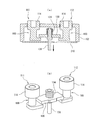
- the electromagnet unit 200 includes a U-shaped magnetic yoke 201 that is flat when viewed from the side, and a cylindrical auxiliary yoke 203 is fixed to the center of the bottom plate portion 202 of the magnetic yoke 201. Yes.
- a spool 204 as a plunger driving unit is disposed outside the cylindrical auxiliary yoke 203.
- the spool 204 includes a central cylindrical portion 205 that passes through the cylindrical auxiliary yoke 203, a lower flange portion 206 that protrudes radially outward from the lower end portion of the central cylindrical portion 205, and a little more than the upper end of the central cylindrical portion 205.
- the upper flange portion 207 protrudes radially outward from the lower side.
- An exciting coil 208 is wound around a storage space formed by the central cylindrical portion 205, the lower flange portion 206, and the upper flange portion 207.
- the upper magnetic yoke 210 is fixed between the upper ends of the magnetic yoke 201 serving as the open end.
- the upper magnetic yoke 210 is formed with a through hole 210 a facing the central cylindrical portion 205 of the spool 204 at the central portion.
- a movable plunger 215 having a return spring 214 disposed between the bottom portion and the bottom plate portion 202 of the magnetic yoke 201 is slidably disposed.
- the movable plunger 215 is formed with a peripheral flange portion 216 protruding outward in the radial direction at an upper end portion protruding upward from the upper magnetic yoke 210.
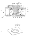
- annular permanent magnet 220 formed in an annular shape is fixed on the upper surface of the upper magnetic yoke 210 so as to surround the peripheral flange portion 216 of the movable plunger 215.
- the annular permanent magnet 220 has a rectangular outer shape and has a through hole 221 that surrounds the peripheral flange 216 at the center.
- the annular permanent magnet 220 is magnetized so that the upper end side is, for example, an N pole and the lower end side is an S pole in the vertical direction, that is, the thickness direction.
- the shape of the through-hole 221 of the annular permanent magnet 220 is a shape that matches the shape of the peripheral flange portion 216, and the shape of the outer peripheral surface can be an arbitrary shape such as a circle or a square.
- the outer shape of the annular permanent magnet 220 is not limited to a rectangular shape, but may be any shape such as a circle or a hexagon.
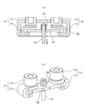
- auxiliary yoke 225 having the same outer shape as that of the annular permanent magnet 220 is fixed to the upper end surface of the annular permanent magnet 220.
- the auxiliary yoke 225 has a rectangular flat plate portion 225a fixed to the upper surface of the annular permanent magnet 220, and is formed to project downward from the central portion of the rectangular flat plate portion 225a.
- a step plate 225c having a central opening 225b through which the connecting shaft 131 is inserted.
- the center opening 225b and the step plate portion 225c are integrally formed by press molding. In this manner, by forming the step plate portion 225c in the auxiliary yoke 225, the rigidity of the auxiliary yoke 225 can be increased, and deformation of the auxiliary yoke 225 can be prevented.
- the peripheral flange 216 of the movable plunger 215 is brought into contact with the lower surface of the step plate 225c by the elasticity of the return spring 214 and the magnetic force of the annular permanent magnet 220, so that the insertion position of the movable plunger 215 is It is regulated.
- the thickness T of the annular permanent magnet 220 includes the stroke L of the movable plunger 215, the thickness t of the peripheral flange portion 216 of the movable plunger 215, and the rectangular flat plate portion of the auxiliary yoke 225.
- the thickness T of the annular permanent magnet 220 can be arbitrarily set according to the required electromagnetic force, and the stroke L of the movable plunger 215 is set to the height y between the rectangular flat plate portion 225a and the step plate portion 225c of the auxiliary yoke 225. Can be adjusted.
- the cumulative number of parts and shape tolerances that affect the stroke of the movable plunger 215 can be minimized. Therefore, when the stroke L of the movable plunger 215 is determined, the thickness T of the annular permanent magnet 220 and the thickness of the peripheral flange 216 of the movable plunger 215 are determined, and finally the height y of the auxiliary yoke 225 is determined.
- the stroke L can be adjusted, and variations in the stroke L can be minimized. In particular, it is more effective when the stroke is small with a small electromagnetic contactor.
- the permanent magnet is the annular permanent magnet 220
- the number of parts is reduced and the cost is reduced as compared with the case where two permanent magnets are arranged on the left and right sides as described in Patent Documents 1 and 2. I can plan.
- the peripheral flange portion 216 of the movable plunger 215 is disposed in the vicinity of the inner peripheral surface of the through hole 221 formed in the annular permanent magnet 220, there is no waste in the closed circuit through which the magnetic flux generated by the annular permanent magnet 220 passes, and the leakage magnetic flux And the magnetic force of the permanent magnet can be used efficiently.
- a connecting shaft 131 that supports the movable contact 130 is screwed to the upper end surface of the movable plunger 215.
- the movable plunger 215 is urged upward by the return spring 214, so that the upper surface of the peripheral flange portion 216 is in a released position where it abuts against the lower surface of the step plate portion 225 c of the auxiliary yoke 225.
- the contact part 130a of the movable contactor 130 is separated upward from the contact part 118a of the fixed contactors 111 and 112, and the current is interrupted.
- the relationship is set as follows. g1 ⁇ g2 and g3 ⁇ g4
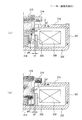
- the exciting coil 208 when excited in the released state, as shown in FIG. 5A, the movable plunger 215 passes through the peripheral flange portion 216, and between the peripheral flange portion 216 and the upper magnetic yoke 210.
- the upper magnetic yoke 210 is reached through the gap g1.
- a closed magnetic path is formed from the upper magnetic yoke 210 through the U-shaped magnetic yoke 201 to the movable plunger 215 through the cylindrical auxiliary yoke 203.
- the magnetic flux density of the gap g1 between the lower surface of the peripheral flange 216 of the movable plunger 215 and the upper surface of the upper magnetic yoke 210 can be increased, and a larger attractive force is generated to move the movable plunger 215 to the return spring. It is lowered against the urging force of 214 and the attractive force of the annular permanent magnet 220. Accordingly, the contact portion 130a of the movable contact 130 connected to the movable plunger 215 via the connecting shaft 131 is brought into contact with the contact portion 118a of the fixed contacts 111 and 112, and is passed from the fixed contact 111 to the movable contact 130. A current path toward the stationary contact 112 is formed, and the input state is established.
- the movable plunger 215 is covered with a cap 230 made of a nonmagnetic material and formed in a bottomed cylindrical shape, and is formed by extending radially outward at the open end of the cap 230.
- the flange portion 231 is sealed to the lower surface of the upper magnetic yoke 210.
- a sealed container is formed in which the arc extinguishing chamber 102 and the cap 230 are communicated with each other via the through hole 210 a of the upper magnetic yoke 210.
- a gas such as hydrogen gas, nitrogen gas, a mixed gas of hydrogen and nitrogen, air, or SF 6 is sealed in a sealed container formed by the arc extinguishing chamber 102 and the cap 230.
- the fixed contact 111 is connected to a power supply source that supplies a large current, for example, and the fixed contact 112 is connected to a load.
- the exciting coil 208 in the electromagnet unit 200 is in a non-excited state and the electromagnet unit 200 is in a released state in which no exciting force for lowering the movable plunger 215 is generated.
- the movable plunger 215 is urged upward by the return spring 214 away from the upper magnetic yoke 210.
- the attractive force due to the magnetic force of the annular permanent magnet 220 is applied to the auxiliary yoke 225, and the peripheral flange portion 216 of the movable plunger 215 is attracted. Therefore, the upper surface of the peripheral flange portion 216 of the movable plunger 215 is in contact with the lower surface of the step plate portion 225c of the auxiliary yoke 225. For this reason, the contact part 130a of the movable contact 130 of the contact mechanism 101 connected to the movable plunger 215 via the connection shaft 131 is spaced apart from the contact part 118a of the fixed contacts 111 and 112 upward by a predetermined distance. . For this reason, the current path between the stationary contacts 111 and 112 is in a disconnected state, and the contact mechanism 101 is in an open state.
- both the urging force by the return spring 214 and the attractive force by the annular permanent magnet 220 are acting on the movable plunger 215, so that the movable plunger 215 is inadvertently caused by external vibration or impact. Therefore, it is possible to reliably prevent malfunction.
- the exciting coil 208 of the electromagnet unit 200 is energized from this released state, an exciting force is generated by the electromagnet unit 200 and the movable plunger 215 is resisted against the biasing force of the return spring 214 and the attractive force of the annular permanent magnet 220. Press down.
- the gap g4 between the bottom surface of the movable plunger 215 and the bottom plate portion 202 of the magnetic yoke 201 is large, and there is almost no magnetic flux passing through the gap g4.
- the cylindrical auxiliary yoke 203 faces the lower outer peripheral surface of the movable plunger 215, and the gap g3 between the movable plunger 215 and the cylindrical auxiliary yoke 203 is set smaller than the gap g4.
- a magnetic path is formed between the movable plunger 215 and the bottom plate portion 202 of the magnetic yoke 201 through the cylindrical auxiliary yoke 203. Further, the gap between the lower surface of the peripheral flange 216 of the movable plunger 215 and the upper magnetic yoke 210 as compared to the gap g2 between the outer peripheral surface of the movable plunger 215 and the inner peripheral surface of the through hole 210a of the upper magnetic yoke 210. g1 is set small.
- the movable plunger 215 quickly descends against the biasing force of the return spring 214 and the attractive force of the annular permanent magnet 220. Accordingly, the lowering of the movable plunger 215 is stopped when the lower surface of the peripheral flange portion 216 contacts the upper surface of the upper magnetic yoke 210 as shown in FIG.
- the movable contact 130 connected to the movable plunger 215 via the connecting shaft 131 is also lowered, and the contact portion 130a thereof is the contact portion 118a of the fixed contacts 111 and 112. In contact with the contact pressure of the contact spring 134.
- the fixed contactors 111 and 112 have a C-shaped portion 115 formed by the upper plate portion 116, the intermediate plate portion 117, and the lower plate portion 118. A current in the reverse direction flows between the plate portion 118 and the movable contact 130 facing the plate portion 118.
- the movable contact 130 is connected to the contact portion 118a of the fixed contacts 111 and 112 according to Fleming's left-hand rule.
- the Lorentz force that presses against the surface can be generated.
- this Lorentz force it becomes possible to resist the electromagnetic repulsion force in the opening direction generated between the contact portions 118a of the fixed contacts 111 and 112 and the contact portion 130a of the movable contact 130, and the contact portion of the movable contact 130 It is possible to reliably prevent the 130a from opening.
- the pressing force of the contact spring 134 that supports the movable contact 130 can be reduced, and the thrust generated by the exciting coil 208 can be reduced accordingly, and the configuration of the entire electromagnetic contactor can be reduced in size. can do.
- the excitation of the excitation coil 208 of the electromagnet unit 200 is stopped.
- the exciting force that moves the movable plunger 215 downward by the electromagnet unit 200 disappears, so that the movable plunger 215 rises by the urging force of the return spring 214, and the annular permanent magnet 216 as the peripheral flange 216 approaches the auxiliary yoke 225.
- the suction force of 220 increases.
- the movable plunger 215 rises the movable contact 130 connected via the connecting shaft 131 rises.
- the movable contact 130 is in contact with the stationary contacts 111 and 112 while the contact pressure is applied by the contact spring 134. After that, when the contact pressure of the contact spring 134 disappears, the movable contact 130 is in an open state in which it is separated upward from the fixed contacts 111 and 112.
- both end portions of the movable contact 130 and the upper plate portion 116 and the intermediate plate portion of the C-shaped portion 115 are covered.
- the insulation cover 121 between 117 can secure an insulation distance, and the height of the movable contact 130 in the movable direction can be shortened. Therefore, the contact device 100 can be reduced in size.
- the magnetic field generated by the current flowing through the intermediate plate portion 117 is shielded by the magnetic plate 119. .
- the magnetic field generated by the arc generated between the contact portions 118a of the fixed contacts 111 and 112 and the contact portion 130a of the movable contact 130 does not interfere with the magnetic field generated by the current flowing through the intermediate plate portion 117. It is possible to prevent the arc from being affected by the magnetic field generated by the current flowing through the plate portion 117.
- the C-shaped portion 115 of the fixed contacts 111 and 112 and the contact spring 134 that applies the contact pressure of the movable contact 130 are arranged in parallel.
- the height of the contact mechanism 101 can be reduced as compared with the case where the fixed contact, the movable contact, and the contact spring are arranged in series. For this reason, the contact device 100 can be reduced in size.
- the arc extinguishing chamber 102 is formed by brazing the metal rectangular tube 104 and the upper surface thereof, and brazing the fixed contact support insulating substrate 105 having a flat plate shape for fixing and holding the fixed contacts 111 and 112 by brazing. I am doing so.
- the fixed contact supporting insulating substrates 105 can be arranged in close contact vertically and horizontally on the same plane, and a plurality of fixed contact supporting insulating substrates 105 can be metallized at a time to improve productivity. Can be made.
- the fixed contacts 111 and 112 can be brazed and supported on the fixed contact supporting insulating substrate 105 and then brazed to the metal square cylinder 104, and the fixed contacts 111 and 112 can be easily fixed and held.
- the brazing jig can be configured simply and the cost of the assembling jig can be reduced.
- the flatness of the fixed contact supporting insulating substrate 105 and the suppression and management of the warpage are also easier than in the case where the arc extinguishing chamber 102 is formed in a bowl shape. Further, it is possible to manufacture the arc extinguishing chamber 102 in a large quantity, and the manufacturing cost can be reduced.
- the annular permanent magnet 220 magnetized in the movable direction of the movable plunger 215 is disposed on the upper magnetic yoke 210, and the auxiliary yoke 225 is formed on the upper surface thereof.
- a suction force for sucking the peripheral flange portion 216 of the movable plunger 215 can be generated.
- the movable plunger 215 in the released state can be fixed by the magnetic force of the annular permanent magnet 220 and the urging force of the return spring 214, the holding force against the malfunction impact can be improved.
- the urging force of the return spring 214 can be reduced, and the total load due to the contact spring 134 and the return spring 214 can be reduced. Therefore, it is possible to reduce the attractive force generated in the exciting coil 208 according to the decrease in the total load, and the magnetomotive force of the exciting coil 208 can be reduced. For this reason, the axial length of the spool 204 can be shortened, and the height of the movable plunger 215 of the electromagnet unit 200 in the movable direction can be reduced.
- the auxiliary yoke 225 is integrally formed of the rectangular flat plate portion 225a and the step plate portion 225c having the central opening 225b, the rigidity is increased as compared with the case where the auxiliary yoke 225 is formed of only the rectangular flat plate portion 225a.
- the auxiliary yoke 225 can be prevented from being deformed. For this reason, when changing from the charged state to the released state, the movable plunger 215 moves upward by the elastic force of the return spring 214 and the magnetic force of the annular permanent magnet 220, and the upper surface of the peripheral flange portion 216 of the movable plunger 215 is the auxiliary yoke. Although it comes into contact with the lower surface of the step plate portion 225c of 225, since the auxiliary yoke 225 has high rigidity, the release position of the movable plunger 215 can be accurately regulated and positioned.
- the step plate 225c is formed in the auxiliary yoke 225, the height of the annular permanent magnet 220 is arbitrarily set according to the required magnetic force regardless of the stroke L of the movable plunger 215 and the thickness t of the peripheral flange 216.
- the final position adjustment can be adjusted by the height y of the step plate portion 225c of the auxiliary yoke 225.
- the cumulative number of parts and shape tolerances that affect the stroke of the movable plunger 215 can be minimized.
- the stroke adjustment of the movable plunger 215 is performed only by the thickness of the annular permanent magnet 220 and the thickness of the peripheral flange portion 216 of the movable plunger 215, the stroke variation can be minimized.
- the auxiliary yoke 225 can be easily formed with one component. Further, since the thickness of the peripheral flange portion 216 of the movable plunger 215 can be set to a minimum necessary thickness, the mass of the movable plunger 215 can be reduced, and the elastic force of the return spring 214 can be reduced accordingly. Thus, the whole can be reduced in weight and size.
- the overall configuration of the electromagnetic contactor 10 can be greatly shortened and the size can be reduced. Can be planned. Further, by disposing the peripheral flange 216 of the movable plunger 215 in the inner peripheral surface of the annular permanent magnet 220, there is no waste in the closed magnetic path through which the magnetic flux generated from the annular permanent magnet 220 passes, and the permanent magnet is reduced by reducing the leakage magnetic flux. Can be used efficiently.
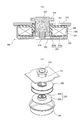
- the present invention is not limited to the above-described configuration.
- the configuration is as shown in FIG. That is, the step plate portion 225e in which the central opening 225d of the auxiliary yoke 225 is formed protrudes upward from the rectangular flat plate portion 225a, and the height between the lower surface of the rectangular flat plate portion 225a and the lower surface of the step plate portion 225e of the auxiliary yoke 225 is increased.
- the stroke L of the movable plunger 215 may be ensured by the length y.
- the arc-extinguishing chamber 102 of the contact apparatus 100 was comprised with the metal square cylinder 104 and the fixed contact support insulation board
- substrate 105 was demonstrated, it is not limited to this, Other structures It can be.
- a rectangular tube portion 301 and a top plate portion 302 that closes the upper end thereof are integrally formed with ceramics or a synthetic resin material to form a bowl-shaped body 303.
- the arc-extinguishing chamber 102 may be formed by forming a metal foil on the open end face side of the bowl-shaped body 303 to form a metal foil, and sealing and joining a metal connecting member 304 to the metal foil.
- the contact mechanism 101 is not limited to the structure of the said embodiment,
- the contact mechanism of arbitrary structures can be applied.
- an L-shaped portion 160 having a shape in which the upper plate portion 116 in the C-shaped portion 115 is omitted may be coupled to the support conductor portion 114.
- the recess 132 may be omitted and formed in a flat plate shape.
- the connecting shaft 131 is screwed to the movable plunger 215 .
- the present invention is not limited to screwing, and any connection method can be applied.
- the movable plunger 215 and the connecting shaft can be applied.
- 131 may be integrally formed.
- connection between the connecting shaft 131 and the movable contact 130 forms a flange portion 131a at the tip of the connecting shaft 131, and the lower end of the movable contact 130 is inserted into the C after inserting the contact spring 134 and the movable contact 130.
- it is not limited to this. That is, a positioning large-diameter portion that protrudes in the radial direction is formed at the C-ring position of the connecting shaft 131, and the contact spring 134 is disposed after the movable contact 130 is brought into contact with the positioning large-diameter portion. You may make it fix with a ring.
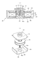
- the magnetic yoke 201 is formed in a bottomed cylindrical shape as shown in FIGS. 10A and 10B, and the cylindrical auxiliary yoke 203 is formed with an annular plate portion 203 a along the bottom plate portion 202 of the magnetic yoke 201. You may make it comprise with the cylindrical part 203b which rises upwards from the internal peripheral surface of this annular
- a through hole 202a is formed in the bottom plate portion 202 of the U-shaped magnetic yoke 210, and a convex cylindrical auxiliary yoke 203 is provided in the through hole 202a.
- the small diameter portion 203c of the cylindrical auxiliary yoke 203 may be inserted into an insertion hole 217 formed in the movable plunger 215.
- the sealed container was comprised with the arc-extinguishing chamber 102 and the cap 230, and the case where gas was enclosed in this sealed container was demonstrated, it is not limited to this, The electric current to interrupt
- an electromagnetic contactor that can secure a necessary magnetic force with one permanent magnet without using a plurality of permanent magnets and can efficiently use the magnetic force of the permanent magnet.
- Electromagnetic contactor 11 ... Exterior insulation container, 100 ... Contact apparatus, 101 ... Contact mechanism, 102 ... Arc-extinguishing chamber, 104 ... Metal square cylinder, 105 ... Fixed contact support insulation board, 111, 112 ... Fixed contact 114 ... Support conductor part, 115 ... C-shaped part, 116 ... Upper plate part, 117 ... Intermediate plate part, 118 ... Lower plate part, 118a ... Contact part, 121 ... Insulating cover, 122 ... L-shaped plate part, 123, 124 ... side plate part, 125 ... fitting part, 130 ... movable contact, 130a ... contact part, 131 ...
Abstract
Priority Applications (4)
| Application Number | Priority Date | Filing Date | Title |
|---|---|---|---|
| EP13800184.7A EP2860749A4 (fr) | 2012-06-08 | 2013-05-09 | Contacteur électromagnétique |
| CN201380018962.3A CN104221118B (zh) | 2012-06-08 | 2013-05-09 | 电磁接触器 |
| KR1020147027735A KR20150016485A (ko) | 2012-06-08 | 2013-05-09 | 전자 접촉기 |
| US14/505,009 US9514896B2 (en) | 2012-06-08 | 2014-10-02 | Electromagnetic contactor |
Applications Claiming Priority (2)
| Application Number | Priority Date | Filing Date | Title |
|---|---|---|---|
| JP2012131236A JP5965218B2 (ja) | 2012-06-08 | 2012-06-08 | 電磁接触器 |
| JP2012-131236 | 2012-06-08 |
Related Child Applications (1)
| Application Number | Title | Priority Date | Filing Date |
|---|---|---|---|
| US14/505,009 Continuation US9514896B2 (en) | 2012-06-08 | 2014-10-02 | Electromagnetic contactor |
Publications (1)
| Publication Number | Publication Date |
|---|---|
| WO2013183224A1 true WO2013183224A1 (fr) | 2013-12-12 |
Family
ID=49711633
Family Applications (1)
| Application Number | Title | Priority Date | Filing Date |
|---|---|---|---|
| PCT/JP2013/002991 WO2013183224A1 (fr) | 2012-06-08 | 2013-05-09 | Contacteur électromagnétique |
Country Status (6)
| Country | Link |
|---|---|
| US (1) | US9514896B2 (fr) |
| EP (1) | EP2860749A4 (fr) |
| JP (1) | JP5965218B2 (fr) |
| KR (1) | KR20150016485A (fr) |
| CN (1) | CN104221118B (fr) |
| WO (1) | WO2013183224A1 (fr) |
Cited By (2)
| Publication number | Priority date | Publication date | Assignee | Title |
|---|---|---|---|---|
| US20150054606A1 (en) * | 2012-06-08 | 2015-02-26 | Fuji Electric Fa Components & Systems Co., Ltd. | Electromagnetic contactor |
| CN107527768A (zh) * | 2016-06-17 | 2017-12-29 | 松下知识产权经营株式会社 | 电磁铁装置以及搭载了该电磁铁装置的电磁继电器 |
Families Citing this family (12)
| Publication number | Priority date | Publication date | Assignee | Title |
|---|---|---|---|---|
| JP6265657B2 (ja) * | 2013-08-26 | 2018-01-24 | 富士通コンポーネント株式会社 | 電磁継電器 |
| KR200489974Y1 (ko) * | 2015-04-23 | 2019-09-03 | 엘에스산전 주식회사 | 전자접촉기 액추에이터 |
| JP6274229B2 (ja) * | 2016-01-27 | 2018-02-07 | 富士電機機器制御株式会社 | 接点装置及びこれを使用した電磁接触器 |
| CN105895452B (zh) * | 2016-05-27 | 2017-11-10 | 浙江英洛华新能源科技有限公司 | 密封型高压直流继电器 |
| ES2745859T3 (es) * | 2016-06-13 | 2020-03-03 | Abb Schweiz Ag | Contactor de media tensión |
| CN105914104B (zh) * | 2016-06-14 | 2018-11-20 | 哈尔滨工业大学 | 一种双永磁长短轭铁极面单稳态电磁机构 |
| CN105914103B (zh) * | 2016-06-14 | 2018-11-20 | 哈尔滨工业大学 | 一种双永磁大小极面单稳态电磁机构 |
| CN106024525B (zh) * | 2016-06-14 | 2018-11-20 | 哈尔滨工业大学 | 一种双永磁非对称极面单稳态电磁机构 |
| JP6490643B2 (ja) * | 2016-09-30 | 2019-03-27 | 本田技研工業株式会社 | 鞍乗り型車両の電装品支持構造 |
| DE102018208119A1 (de) | 2018-05-23 | 2019-11-28 | Ellenberger & Poensgen Gmbh | Trennvorrichtung zur Gleichstromunterbrechung eines Strompfades sowie Schutzschalter |
| JP7259669B2 (ja) * | 2019-09-19 | 2023-04-18 | 富士電機機器制御株式会社 | 電磁接触器 |
| KR20230051482A (ko) * | 2020-07-22 | 2023-04-18 | 기가백, 엘엘씨 | 부상 퓨즈 장치 |
Citations (7)
| Publication number | Priority date | Publication date | Assignee | Title |
|---|---|---|---|---|
| JPS5461262U (fr) * | 1977-10-07 | 1979-04-27 | ||
| JPH01268005A (ja) * | 1988-04-19 | 1989-10-25 | Omron Tateisi Electron Co | 電磁石装置 |
| JPH0291901A (ja) | 1988-09-29 | 1990-03-30 | Mitsubishi Electric Corp | 有極電磁石装置 |
| US5959519A (en) | 1996-03-06 | 1999-09-28 | Siemens Ag | Electromagnetic switching device |
| JP2000331587A (ja) * | 1999-04-19 | 2000-11-30 | Kmw Co Ltd | ソレノイドを利用したスイッチ |
| JP2005209839A (ja) * | 2004-01-22 | 2005-08-04 | Nippon Pulse Motor Co Ltd | リニアアクチュエータ |
| JP2010062079A (ja) * | 2008-09-05 | 2010-03-18 | Mitsubishi Electric Corp | 有極電磁石、電磁接触器、電磁開閉器、及び有極電磁石の製造方法 |
Family Cites Families (10)
| Publication number | Priority date | Publication date | Assignee | Title |
|---|---|---|---|---|
| DE19720858A1 (de) * | 1997-05-17 | 1998-11-19 | Smb Schwede Maschinenbau Gmbh | Elektromagnetische Betätigungsvorrichtung |
| CN101341564B (zh) * | 2005-12-22 | 2011-04-06 | 西门子公司 | 用于驱动开关设备的方法和装置 |
| JP2007273289A (ja) * | 2006-03-31 | 2007-10-18 | Omron Corp | 電磁継電器 |
| CN201171024Y (zh) * | 2008-01-29 | 2008-12-24 | 江苏中金电器设备有限公司 | 永磁式接触器操动机构 |
| JP5163318B2 (ja) * | 2008-06-30 | 2013-03-13 | オムロン株式会社 | 電磁石装置 |
| KR101004465B1 (ko) * | 2008-09-05 | 2010-12-31 | 엘에스산전 주식회사 | 계전기 |
| JP2010192416A (ja) * | 2009-01-21 | 2010-09-02 | Panasonic Electric Works Co Ltd | 封止接点装置 |
| JP5197480B2 (ja) * | 2009-05-14 | 2013-05-15 | 株式会社日本自動車部品総合研究所 | 電磁継電器 |
| JP5981756B2 (ja) * | 2012-04-13 | 2016-08-31 | 富士電機機器制御株式会社 | 電磁接触器 |
| JP5965218B2 (ja) * | 2012-06-08 | 2016-08-03 | 富士電機機器制御株式会社 | 電磁接触器 |
-
2012
- 2012-06-08 JP JP2012131236A patent/JP5965218B2/ja active Active
-
2013
- 2013-05-09 WO PCT/JP2013/002991 patent/WO2013183224A1/fr active Application Filing
- 2013-05-09 EP EP13800184.7A patent/EP2860749A4/fr not_active Withdrawn
- 2013-05-09 CN CN201380018962.3A patent/CN104221118B/zh not_active Expired - Fee Related
- 2013-05-09 KR KR1020147027735A patent/KR20150016485A/ko not_active Application Discontinuation
-
2014
- 2014-10-02 US US14/505,009 patent/US9514896B2/en active Active
Patent Citations (7)
| Publication number | Priority date | Publication date | Assignee | Title |
|---|---|---|---|---|
| JPS5461262U (fr) * | 1977-10-07 | 1979-04-27 | ||
| JPH01268005A (ja) * | 1988-04-19 | 1989-10-25 | Omron Tateisi Electron Co | 電磁石装置 |
| JPH0291901A (ja) | 1988-09-29 | 1990-03-30 | Mitsubishi Electric Corp | 有極電磁石装置 |
| US5959519A (en) | 1996-03-06 | 1999-09-28 | Siemens Ag | Electromagnetic switching device |
| JP2000331587A (ja) * | 1999-04-19 | 2000-11-30 | Kmw Co Ltd | ソレノイドを利用したスイッチ |
| JP2005209839A (ja) * | 2004-01-22 | 2005-08-04 | Nippon Pulse Motor Co Ltd | リニアアクチュエータ |
| JP2010062079A (ja) * | 2008-09-05 | 2010-03-18 | Mitsubishi Electric Corp | 有極電磁石、電磁接触器、電磁開閉器、及び有極電磁石の製造方法 |
Non-Patent Citations (1)
| Title |
|---|
| See also references of EP2860749A4 * |
Cited By (3)
| Publication number | Priority date | Publication date | Assignee | Title |
|---|---|---|---|---|
| US20150054606A1 (en) * | 2012-06-08 | 2015-02-26 | Fuji Electric Fa Components & Systems Co., Ltd. | Electromagnetic contactor |
| US9514896B2 (en) * | 2012-06-08 | 2016-12-06 | Fuji Electric Fa Components & Systems Co., Ltd. | Electromagnetic contactor |
| CN107527768A (zh) * | 2016-06-17 | 2017-12-29 | 松下知识产权经营株式会社 | 电磁铁装置以及搭载了该电磁铁装置的电磁继电器 |
Also Published As
| Publication number | Publication date |
|---|---|
| US20150054606A1 (en) | 2015-02-26 |
| JP2013254712A (ja) | 2013-12-19 |
| KR20150016485A (ko) | 2015-02-12 |
| EP2860749A1 (fr) | 2015-04-15 |
| CN104221118B (zh) | 2017-03-08 |
| EP2860749A4 (fr) | 2016-04-06 |
| JP5965218B2 (ja) | 2016-08-03 |
| US9514896B2 (en) | 2016-12-06 |
| CN104221118A (zh) | 2014-12-17 |
Similar Documents
| Publication | Publication Date | Title |
|---|---|---|
| JP5965218B2 (ja) | 電磁接触器 | |
| JP5684649B2 (ja) | 電磁接触器 | |
| JP5727860B2 (ja) | 電磁接触器 | |
| EP2711965B1 (fr) | Contacteur électromagnétique | |
| JP5727862B2 (ja) | 電磁接触器 | |
| US8994482B2 (en) | Electromagnetic contactor | |
| WO2012157176A1 (fr) | Contacteur électromagnétique | |
| JP5990090B2 (ja) | 電磁開閉器 | |
| JP5727861B2 (ja) | 電磁接触器 | |
| JP5864902B2 (ja) | 電磁接触器の消弧室組立方法 | |
| JP5981756B2 (ja) | 電磁接触器 | |
| WO2014076865A1 (fr) | Commutateur électromagnétique | |
| WO2014080555A1 (fr) | Contacteur d'électroaimant | |
| JP2015176810A (ja) | 電磁接触器 | |
| JP2021048059A (ja) | 電磁接触器 | |
| JP2016062691A (ja) | 電磁接触器 |
Legal Events
| Date | Code | Title | Description |
|---|---|---|---|
| 121 | Ep: the epo has been informed by wipo that ep was designated in this application |
Ref document number: 13800184 Country of ref document: EP Kind code of ref document: A1 |
|
| ENP | Entry into the national phase |
Ref document number: 20147027735 Country of ref document: KR Kind code of ref document: A |
|
| REEP | Request for entry into the european phase |
Ref document number: 2013800184 Country of ref document: EP |
|
| WWE | Wipo information: entry into national phase |
Ref document number: 2013800184 Country of ref document: EP |
|
| NENP | Non-entry into the national phase |
Ref country code: DE |