以下、本発明の実施の形態を図面に基づいて説明する。
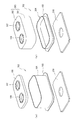
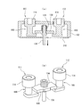
図1は本発明に係る電磁開閉器の一例を示す断面図、図2は消弧室の分解斜視図である。この図1及び図2において、10は電磁接触器であり、この電磁接触器10は接点機構を配置した接点装置100と、この接点装置100を駆動する電磁石ユニット200とで構成されている。
接点装置100は、図1及び図2から明らかなように、接点機構101を収納する消弧室102を有する。この消弧室102は、図2(a)に示すように、金属製の下端部に外方と突出するフランジ部103を有する金属角筒体104と、この金属角筒体104の上端を閉塞する平板状のセラミック絶縁基板で構成される固定接点支持絶縁基板105とを備えている。
Hereinafter, an embodiment of the present invention with reference to the accompanying drawings.
FIG. 1 is a sectional view showing an example of an electromagnetic switch according to the present invention, and FIG. 2 is an exploded perspective view of an arc extinguishing chamber. 1 and 2, reference numeral 10 denotes an electromagnetic contactor. The electromagnetic contactor 10 includes a contact device 100 having a contact mechanism and an electromagnet unit 200 that drives the contact device 100.
As is apparent from FIGS. 1 and 2, the contact device 100 includes an arc extinguishing chamber 102 that houses the contact mechanism 101. As shown in FIG. 2A, the arc extinguishing chamber 102 has a metal rectangular tube body 104 having a flange portion 103 protruding outward at a metal lower end portion, and the upper end of the metal square tube body 104 is closed. And a fixed contact supporting insulating substrate 105 composed of a flat ceramic insulating substrate.
金属角筒体104は、そのフランジ部103が後述する電磁石ユニット200の上部磁気ヨーク210にシール接合されて固定されている。
また、固定接点支持絶縁基板105には、中央部に後述する一対の固定接触子111及び112を挿通する貫通孔106及び107が所定間隔を保って形成されている。この固定接点支持絶縁基板105の上面側における貫通孔106及び107の周囲及び下面側における金属角筒体104に接触する位置にメタライズ処理が施されている。このメタライズ処理を行うには、平面上に複数の固定接点支持絶縁基板105を縦横に配列した状態で、貫通孔106及び107の周囲及び金属角筒体104に接触する位置に銅箔を形成する。
The metal rectangular tube 104 is fixed by being sealed and bonded to an upper magnetic yoke 210 of an electromagnet unit 200 whose flange 103 is described later.
Further, through holes 106 and 107 through which a pair of fixed contacts 111 and 112 (described later) are inserted are formed in the fixed contact supporting insulating substrate 105 at a central portion with a predetermined interval. A metallization process is applied to positions around the through- holes 106 and 107 on the upper surface side of the fixed contact supporting insulating substrate 105 and a position in contact with the metal rectangular cylinder 104 on the lower surface side. In order to perform this metallization process, a copper foil is formed around the through- holes 106 and 107 and at a position in contact with the metal rectangular cylinder 104 with a plurality of fixed contact support insulating substrates 105 arranged vertically and horizontally on a plane. .
接点機構101は、図1に示すように、消弧室102の固定接点支持絶縁基板105の貫通孔106及び107に挿通されて固定された一対の固定接触子111及び112を備えている。これら固定接触子111及び112のそれぞれは、固定接点支持絶縁基板105の貫通孔106及び107に挿通される上端に外方に突出するフランジ部113を有する支持導体部114と、この支持導体部114に連結されて固定接点支持絶縁基板105の下面側に配設され内方側を開放したC字状部115とを備えている。
As shown in FIG. 1, the contact mechanism 101 includes a pair of fixed contacts 111 and 112 that are inserted into and fixed to the through holes 106 and 107 of the fixed contact support insulating substrate 105 of the arc extinguishing chamber 102. Each of the fixed contacts 111 and 112 includes a support conductor portion 114 having a flange portion 113 protruding outward at an upper end inserted through the through holes 106 and 107 of the fixed contact support insulating substrate 105, and the support conductor portion 114. And a C-shaped portion 115 disposed on the lower surface side of the fixed contact supporting insulating substrate 105 and having an inner side open.
C字状部115は、固定接点支持絶縁基板105の下面に沿って外側に延長する上板部116と、この上板部116の外側端部から下方に延長する中間板部117と、この中間板部117の下端側から上板部116と平行に内方側すなわち固定接触子111及び112の対面方向に延長する下板部118とで中間板部117及び下板部118で形成されるL字状に上板部116を加えたC字状に形成されている。
The C-shaped portion 115 includes an upper plate portion 116 that extends outward along the lower surface of the fixed contact supporting insulating substrate 105, an intermediate plate portion 117 that extends downward from the outer end portion of the upper plate portion 116, and an intermediate portion L formed by the intermediate plate portion 117 and the lower plate portion 118 from the lower end side of the plate portion 117 to the inner side parallel to the upper plate portion 116, that is, the lower plate portion 118 extending in the facing direction of the fixed contacts 111 and 112. It is formed in a C shape by adding an upper plate portion 116 to the shape.
ここで、支持導体部114とC字状部115とは、支持導体部114の下端面に突出形成されたピン114aをC字状部115の上板部116に形成された貫通孔120内に挿通した状態で例えばロウ付け等によって固定されている。なお、支持導体部114及びC字状部115の固定は、ロウ付け等に限らず、ピン114aを貫通孔120に嵌合させたり、ピン114aに雄ねじを形成し、貫通孔120に雌ねじを形成して両者を螺合させたりしてもよい。
Here, the support conductor portion 114 and the C-shaped portion 115 include a pin 114 a that protrudes from the lower end surface of the support conductor portion 114 in the through hole 120 formed in the upper plate portion 116 of the C-shaped portion 115. In the inserted state, it is fixed by brazing, for example. The fixing of the support conductor 114 and the C-shaped portion 115 is not limited to brazing or the like, but the pin 114a is fitted into the through hole 120, the male screw is formed on the pin 114a, and the female screw is formed on the through hole 120. Then, they may be screwed together.
そして、固定接触子111及び112のC字状部115にそれぞれ、アークの発生を規制する合成樹脂材製の絶縁カバー121が装着されている。この絶縁カバー121は、C字状部115の上板部116及び中間板部117の内周面を被覆するものである。
このように、固定接触子111及び112のC字状部115に絶縁カバー121を装着することにより、このC字状部115の内周面では下板部118の上面側のみが露出されて接点部118aとされている。
Then, an insulating cover 121 made of a synthetic resin material that restricts the generation of an arc is attached to each of the C-shaped portions 115 of the fixed contacts 111 and 112. The insulating cover 121 covers the inner peripheral surfaces of the upper plate portion 116 and the intermediate plate portion 117 of the C-shaped portion 115.
As described above, by attaching the insulating cover 121 to the C-shaped portion 115 of the fixed contacts 111 and 112, only the upper surface side of the lower plate portion 118 is exposed on the inner peripheral surface of the C-shaped portion 115, and the contact is made. Part 118a.
そして、固定接触子111及び112のC字状部115内に両端部を配置するように可動接触子130が配設されている。この可動接触子130は後述する電磁石ユニット200の可動プランジャ215に固定された連結軸131に支持されている。この可動接触子130は、中央部の連結軸131の近傍が下方に突出する凹部132が形成され、この凹部132に連結軸131を挿通する貫通孔133が形成されている。
And the movable contact 130 is arrange | positioned so that both ends may be arrange | positioned in the C-shaped part 115 of the stationary contacts 111 and 112. FIG. The movable contact 130 is supported by a connecting shaft 131 fixed to a movable plunger 215 of an electromagnet unit 200 described later. The movable contact 130 is formed with a recess 132 that protrudes downward in the vicinity of the central connection shaft 131, and a through-hole 133 through which the connection shaft 131 is inserted is formed in the recess 132.
連結軸131は、上端に外方に突出するフランジ部131aが形成されている。この連結軸131に下端側から接触スプリング134に挿通し、次いで可動接触子130の貫通孔133を挿通して、接触スプリング134の上端をフランジ部131aに当接させ、この接触スプリング134で所定の付勢力を得るように可動接触子130を例えばCリング135によって位置決めする。
The connecting shaft 131 has a flange 131a protruding outward at the upper end. The connecting shaft 131 is inserted into the contact spring 134 from the lower end side, and then inserted into the through hole 133 of the movable contact 130, so that the upper end of the contact spring 134 is brought into contact with the flange portion 131a. The movable contact 130 is positioned by, for example, a C ring 135 so as to obtain an urging force.
この可動接触子130は、釈放状態で、両端の接点部と固定接触子111及び112のC字状部115の下板部118の接点部118aとが所定間隔を保って離間した状態となる。また、可動接触子130は、投入位置で、両端の接点部が固定接触子111及び112のC字状部115の下板部118の接点部118aに、接触スプリング134による所定の接触圧で接触するように設定されている。
In the released state, the movable contact 130 is in a state in which the contact portions at both ends and the contact portion 118a of the lower plate portion 118 of the C-shaped portion 115 of the fixed contacts 111 and 112 are separated from each other by a predetermined distance. In the movable contact 130, the contact portions at both ends are in contact with the contact portion 118a of the lower plate portion 118 of the C-shaped portion 115 of the fixed contacts 111 and 112 with a predetermined contact pressure by the contact spring 134 at the closing position. It is set to be.
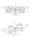
さらに、消弧室102の金属角筒体104の内周面には、図3に示すように、例えば合成樹脂製の絶縁筒体140が配設され、この絶縁筒体140の可動接触子130の側面に対向する位置に磁石収納ポケット141及び142が形成されている。この磁石収納ポケット141及び142には、アーク消弧用永久磁石143及び144が挿通されて固定されている。
Further, as shown in FIG. 3, for example, an insulating cylinder 140 made of synthetic resin is disposed on the inner peripheral surface of the metal rectangular cylinder 104 of the arc extinguishing chamber 102, and the movable contact 130 of the insulating cylinder 140 is arranged. Magnet storage pockets 141 and 142 are formed at positions facing the side surfaces of the magnet storage pockets. In the magnet storage pockets 141 and 142, arc extinguishing permanent magnets 143 and 144 are inserted and fixed.
このアーク消弧用永久磁石143及び144は、厚み方向に互いの対向面が同極例えばN極となるように着磁されている。そして、磁石収納ポケット141及び142の左右方向の外側にそれぞれアーク消弧空間145及び146が形成されている。
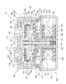
電磁石ユニット200は、図1に示すように、側面から見て扁平なU字形状の磁気ヨーク201を有し、この磁気ヨーク201の底板部202の中央部に円筒状補助ヨーク203が固定されている。この円筒状補助ヨーク203の外側にプランジャ駆動部としてのスプール204が配置されている。
The arc extinguishing permanent magnets 143 and 144 are magnetized so that their opposing surfaces have the same polarity, for example, N pole, in the thickness direction. Arc extinguishing spaces 145 and 146 are formed on the outer sides of the magnet storage pockets 141 and 142 in the left-right direction, respectively.
As shown in FIG. 1, the electromagnet unit 200 includes a U-shaped magnetic yoke 201 that is flat when viewed from the side, and a cylindrical auxiliary yoke 203 is fixed to the center of the bottom plate portion 202 of the magnetic yoke 201. Yes. A spool 204 as a plunger driving unit is disposed outside the cylindrical auxiliary yoke 203.
このスプール204は、円筒状補助ヨーク203を挿通する中央円筒部205と、この中央円筒部205の下端部から半径方向外方に突出する下フランジ部206と、中央円筒部205の上端より僅かに下側から半径方向外方に突出する上フランジ部207とで構成されている。そして、中央円筒部205、下フランジ部206及び上フランジ部207で構成される収納空間に励磁コイル208が巻装されている。
The spool 204 includes a central cylindrical portion 205 that passes through the cylindrical auxiliary yoke 203, a lower flange portion 206 that protrudes radially outward from the lower end portion of the central cylindrical portion 205, and a little more than the upper end of the central cylindrical portion 205. The upper flange portion 207 protrudes radially outward from the lower side. An exciting coil 208 is wound around a storage space formed by the central cylindrical portion 205, the lower flange portion 206, and the upper flange portion 207.
そして、磁気ヨーク201の開放端となる上端間に上部磁気ヨーク210が固定されている。この上部磁気ヨーク210は、中央部にスプール204の中央円筒部205に対向する貫通孔210aが形成されている。
そして、スプール204の中央円筒部205内に、底部と磁気ヨーク201の底板部202との間に復帰スプリング214を配設した可動プランジャ215が上下に摺動可能に配設されている。この可動プランジャ215には、上部磁気ヨーク210から上方に突出する上端部に半径方向外方に突出する周鍔部216が形成されている。
The upper magnetic yoke 210 is fixed between the upper ends of the magnetic yoke 201 serving as the open end. The upper magnetic yoke 210 is formed with a through hole 210 a facing the central cylindrical portion 205 of the spool 204 at the central portion.
In the central cylindrical portion 205 of the spool 204, a movable plunger 215 having a return spring 214 disposed between the bottom portion and the bottom plate portion 202 of the magnetic yoke 201 is slidably disposed. The movable plunger 215 is formed with a peripheral flange portion 216 protruding outward in the radial direction at an upper end portion protruding upward from the upper magnetic yoke 210.
また、上部磁気ヨーク210の上面に、環状に形成された環状永久磁石220が可動プランジャ215の周鍔部216を囲むように固定されている。この環状永久磁石220は外形が長方形に形成され中央部に周鍔部216を囲む貫通孔221を有する。この環状永久磁石220は上下方向すなわち厚み方向に上端側を例えばN極とし、下端側をS極とするように着磁されている。
なお、環状永久磁石220の貫通孔221の形状は周鍔部216の形状に合わせた形状とし、外周面の形状は円形、方形等の任意の形状とすることができる。同様に、環状永久磁石220の外形も長方形状に限らず、円形、六角形等の任意の形状とすることができる。
Further, an annular permanent magnet 220 formed in an annular shape is fixed on the upper surface of the upper magnetic yoke 210 so as to surround the peripheral flange portion 216 of the movable plunger 215. The annular permanent magnet 220 has a rectangular outer shape and has a through hole 221 that surrounds the peripheral flange 216 at the center. The annular permanent magnet 220 is magnetized so that the upper end side is, for example, an N pole and the lower end side is an S pole in the vertical direction, that is, the thickness direction.
The shape of the through-hole 221 of the annular permanent magnet 220 is a shape that matches the shape of the peripheral flange portion 216, and the shape of the outer peripheral surface can be an arbitrary shape such as a circle or a square. Similarly, the outer shape of the annular permanent magnet 220 is not limited to a rectangular shape, but may be any shape such as a circle or a hexagon.
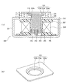
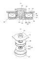
そして、環状永久磁石220の上端面に、環状永久磁石220と同一外形の補助ヨーク225が固定されている。この補助ヨーク225は、図4(a)及び(b)に示すように、環状永久磁石220の上面に固定される長方形平板部225aと、この長方形平板部225aの中央部に下方に突出形成された中央部に連結軸131を挿通する中心開口225bを形成した段差板部225cとで構成されている。
ここで、補助ヨーク225は、プレス成形によって、中心開口225b及び段差板部225cが一体に形成されている。このように、補助ヨーク225に段差板部225cを形成することにより、補助ヨーク225の剛性を高めることができ、補助ヨーク225の変形を防止することができる。
An auxiliary yoke 225 having the same outer shape as that of the annular permanent magnet 220 is fixed to the upper end surface of the annular permanent magnet 220. As shown in FIGS. 4A and 4B, the auxiliary yoke 225 has a rectangular flat plate portion 225a fixed to the upper surface of the annular permanent magnet 220, and is formed to project downward from the central portion of the rectangular flat plate portion 225a. And a step plate 225c having a central opening 225b through which the connecting shaft 131 is inserted.
Here, in the auxiliary yoke 225, the center opening 225b and the step plate portion 225c are integrally formed by press molding. In this manner, by forming the step plate portion 225c in the auxiliary yoke 225, the rigidity of the auxiliary yoke 225 can be increased, and deformation of the auxiliary yoke 225 can be prevented.
そして、釈放状態であるときに、段差板部225cの下面に復帰スプリング214の弾性と環状永久磁石220の磁力とによって可動プランジャ215の周鍔部216が接触されて、可動プランジャ215の投入位置が規制されている。
ここで、環状永久磁石220の厚みTは、図4(a)に示すように、可動プランジャ215のストロークLと、可動プランジャ215の周鍔部216の厚みtと、補助ヨーク225の長方形平板部225aの下面と段差板部225cの下面との高さyとを加算した値(T=L+t+y)に設定されている。したがって、環状永久磁石220の厚みTを必要な電磁力に応じて任意に設定することができ、可動プランジャ215のストロークLを補助ヨーク225の長方形平板部225aと段差板部225cとの高さyで調整することができる。
In the released state, the peripheral flange 216 of the movable plunger 215 is brought into contact with the lower surface of the step plate 225c by the elasticity of the return spring 214 and the magnetic force of the annular permanent magnet 220, so that the insertion position of the movable plunger 215 is It is regulated.
Here, as shown in FIG. 4A, the thickness T of the annular permanent magnet 220 includes the stroke L of the movable plunger 215, the thickness t of the peripheral flange portion 216 of the movable plunger 215, and the rectangular flat plate portion of the auxiliary yoke 225. It is set to a value (T = L + t + y) obtained by adding the height y of the lower surface of 225a and the lower surface of the step plate portion 225c. Therefore, the thickness T of the annular permanent magnet 220 can be arbitrarily set according to the required electromagnetic force, and the stroke L of the movable plunger 215 is set to the height y between the rectangular flat plate portion 225a and the step plate portion 225c of the auxiliary yoke 225. Can be adjusted.
このため、可動プランジャ215のストロークに影響する累積の部品数や形状公差を最小限とすることができる。したがって、可動プランジャ215のストロークLを決定する際に、環状永久磁石220の厚みTと可動プランジャ215の周鍔部216の厚みとを決定しておき、最終的に補助ヨーク225の高さyでストロークLを調整することができ、ストロークLのバラツキを最小化することができる。特に、小型の電磁接触器でストロークが小さい場合により効果的である。
For this reason, the cumulative number of parts and shape tolerances that affect the stroke of the movable plunger 215 can be minimized. Therefore, when the stroke L of the movable plunger 215 is determined, the thickness T of the annular permanent magnet 220 and the thickness of the peripheral flange 216 of the movable plunger 215 are determined, and finally the height y of the auxiliary yoke 225 is determined. The stroke L can be adjusted, and variations in the stroke L can be minimized. In particular, it is more effective when the stroke is small with a small electromagnetic contactor.
また、永久磁石を環状永久磁石220としたので、特許文献1及び2に記載されているように永久磁石を左右対象に2つ配置する場合に比較して、部品点数が少なくなってコストダウンが図れる。また、環状永久磁石220に成形した貫通孔221の内周面近傍に可動プランジャ215の周鍔部216が配置されるため、環状永久磁石220で生じる磁束を通す閉回路に無駄がなく、漏れ磁束が少なくなり、永久磁石の磁力を効率的に使用することができる。
さらに、可動プランジャ215の上端面には可動接触子130を支持する連結軸131が螺着されている。
Further, since the permanent magnet is the annular permanent magnet 220, the number of parts is reduced and the cost is reduced as compared with the case where two permanent magnets are arranged on the left and right sides as described in Patent Documents 1 and 2. I can plan. Further, since the peripheral flange portion 216 of the movable plunger 215 is disposed in the vicinity of the inner peripheral surface of the through hole 221 formed in the annular permanent magnet 220, there is no waste in the closed circuit through which the magnetic flux generated by the annular permanent magnet 220 passes, and the leakage magnetic flux And the magnetic force of the permanent magnet can be used efficiently.
Further, a connecting shaft 131 that supports the movable contact 130 is screwed to the upper end surface of the movable plunger 215.
そして、釈放状態では、可動プランジャ215が復帰スプリング214によって上方に付勢されて、周鍔部216の上面が補助ヨーク225の段差板部225cの下面に当接する釈放位置となる。この状態で、可動接触子130の接点部130aが固定接触子111及び112の接点部118aから上方に離間して、電流遮断状態となっている。
この釈放状態では、可動プランジャ215の周鍔部216が環状永久磁石220の磁力によって補助ヨーク225に吸引されており、復帰スプリング214の付勢力と相まって可動プランジャ215が外部からの振動や衝撃等によって不用意に下方に移動することなく補助ヨーク225に当接された状態が確保される。
In the released state, the movable plunger 215 is urged upward by the return spring 214, so that the upper surface of the peripheral flange portion 216 is in a released position where it abuts against the lower surface of the step plate portion 225 c of the auxiliary yoke 225. In this state, the contact part 130a of the movable contactor 130 is separated upward from the contact part 118a of the fixed contactors 111 and 112, and the current is interrupted.
In this released state, the peripheral flange portion 216 of the movable plunger 215 is attracted to the auxiliary yoke 225 by the magnetic force of the annular permanent magnet 220, and the movable plunger 215 is coupled with the urging force of the return spring 214 due to external vibration or impact. A state of being in contact with the auxiliary yoke 225 is ensured without inadvertently moving downward.
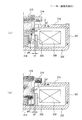
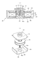
また、釈放状態では、図5(a)に示すように、可動プランジャ215の周鍔部216の下面と上部磁気ヨーク210の上面との間のギャップg1、可動プランジャ215の外周面と上部磁気ヨーク210の貫通孔210aとの間のギャップg2、可動プランジャ215の外周面と円筒状補助ヨーク203との間のギャップg3、可動プランジャ215の下面と磁気ヨーク201の底板部202の上面とのギャップg4と関係が以下のように設定されている。
g1<g2 且つ g3<g4
In the released state, as shown in FIG. 5A, the gap g1 between the lower surface of the peripheral flange 216 of the movable plunger 215 and the upper surface of the upper magnetic yoke 210, the outer peripheral surface of the movable plunger 215, and the upper magnetic yoke 210, a gap g2 between the through-hole 210a, a gap g3 between the outer peripheral surface of the movable plunger 215 and the cylindrical auxiliary yoke 203, a gap g4 between the lower surface of the movable plunger 215 and the upper surface of the bottom plate portion 202 of the magnetic yoke 201. And the relationship is set as follows.
g1 <g2 and g3 <g4
このため、釈放状態で、励磁コイル208を励磁したときに、図5(a)に示すように、可動プランジャ215から周鍔部216を通り、周鍔部216と上部磁気ヨーク210との間のギャップg1を通って上部磁気ヨーク210に達する。この上部磁気ヨーク210からU字状の磁気ヨーク201を通って円筒状補助ヨーク203を通って可動プランジャ215に至る閉磁路が形成される。
For this reason, when the exciting coil 208 is excited in the released state, as shown in FIG. 5A, the movable plunger 215 passes through the peripheral flange portion 216, and between the peripheral flange portion 216 and the upper magnetic yoke 210. The upper magnetic yoke 210 is reached through the gap g1. A closed magnetic path is formed from the upper magnetic yoke 210 through the U-shaped magnetic yoke 201 to the movable plunger 215 through the cylindrical auxiliary yoke 203.
このため、可動プランジャ215の周鍔部216の下面と上部磁気ヨーク210の上面との間のギャップg1の磁束密度を高めることができ、より大きな吸引力を発生して、可動プランジャ215を復帰スプリング214の付勢力及び環状永久磁石220の吸引力に抗して下降させる。
したがって、この可動プランジャ215に連結軸131を介して連結されている可動接触子130の接点部130aを固定接触子111及び112の接点部118aに接触されて固定接触子111から可動接触子130を通じて固定接触子112に向かう電流路が形成されて投入状態となる。
For this reason, the magnetic flux density of the gap g1 between the lower surface of the peripheral flange 216 of the movable plunger 215 and the upper surface of the upper magnetic yoke 210 can be increased, and a larger attractive force is generated to move the movable plunger 215 to the return spring. It is lowered against the urging force of 214 and the attractive force of the annular permanent magnet 220.
Accordingly, the contact portion 130a of the movable contact 130 connected to the movable plunger 215 via the connecting shaft 131 is brought into contact with the contact portion 118a of the fixed contacts 111 and 112, and is passed from the fixed contact 111 to the movable contact 130. A current path toward the stationary contact 112 is formed, and the input state is established.
この投入状態となると、図5(b)に示すように、可動プランジャ215の下端面がU字状の磁気ヨーク201の底板部202に近づくので、前述した各ギャップg1~g4が下記のようになる。
g1<g2 且つ g3>g4
このため、励磁コイル208によって発生される磁束が、図5(b)に示すように、可動プランジャ215から周鍔部216を通って直接上部磁気ヨーク210に入り、この上部磁気ヨーク210からU字状の磁気ヨーク201を通り、その底板部202から直接可動プランジャ215に戻る閉磁路が形成される。
In this input state, as shown in FIG. 5 (b), the lower end surface of the movable plunger 215 approaches the bottom plate portion 202 of the U-shaped magnetic yoke 201, so that the above-mentioned gaps g1 to g4 are as follows. Become.
g1 <g2 and g3> g4
For this reason, the magnetic flux generated by the exciting coil 208 enters the upper magnetic yoke 210 directly from the movable plunger 215 through the peripheral flange portion 216 as shown in FIG. A closed magnetic path that passes through the magnetic yoke 201 and returns directly from the bottom plate portion 202 to the movable plunger 215 is formed.
このため、ギャップg1及びギャップg4で大きな吸引力が作用して可動プランジャ215が下降位置に保持される。このため、可動プランジャ215に連結軸213を介して連結された可動接触子130の接点部130aが固定接触子111及び112の接点部118aへの接触状態が継続される。
Therefore, a large suction force acts on the gap g1 and the gap g4, and the movable plunger 215 is held at the lowered position. For this reason, the contact part 130a of the movable contactor 130 connected to the movable plunger 215 via the connecting shaft 213 is kept in contact with the contact part 118a of the fixed contactors 111 and 112.
そして、可動プランジャ215が、図1に示すように、非磁性体製で有底筒状に形成されたキャップ230で覆われ、このキャップ230の開放端に半径方向外方に延長して形成されたフランジ部231が上部磁気ヨーク210の下面にシール接合されている。これによって、消弧室102及びキャップ230が上部磁気ヨーク210の貫通孔210aを介して連通される密封容器が形成されている。そして、消弧室102及びキャップ230で形成される密封容器内に水素ガス、窒素ガス、水素及び窒素の混合ガス、空気、SF6等のガスが封入されている。
As shown in FIG. 1, the movable plunger 215 is covered with a cap 230 made of a nonmagnetic material and formed in a bottomed cylindrical shape, and is formed by extending radially outward at the open end of the cap 230. The flange portion 231 is sealed to the lower surface of the upper magnetic yoke 210. As a result, a sealed container is formed in which the arc extinguishing chamber 102 and the cap 230 are communicated with each other via the through hole 210 a of the upper magnetic yoke 210. Then, a gas such as hydrogen gas, nitrogen gas, a mixed gas of hydrogen and nitrogen, air, or SF 6 is sealed in a sealed container formed by the arc extinguishing chamber 102 and the cap 230.
次に、上記実施形態の動作を説明する。
今、固定接触子111が例えば大電流を供給する電力供給源に接続され、固定接触子112が負荷に接続されているものとする。
この状態で、電磁石ユニット200における励磁コイル208が非励磁状態にあって、電磁石ユニット200で可動プランジャ215を下降させる励磁力を発生していない釈放状態にあるものとする。この釈放状態では、可動プランジャ215が復帰スプリング214によって、上部磁気ヨーク210から離れる上方向に付勢される。
Next, the operation of the above embodiment will be described.
Now, it is assumed that the fixed contact 111 is connected to a power supply source that supplies a large current, for example, and the fixed contact 112 is connected to a load.
In this state, it is assumed that the exciting coil 208 in the electromagnet unit 200 is in a non-excited state and the electromagnet unit 200 is in a released state in which no exciting force for lowering the movable plunger 215 is generated. In this released state, the movable plunger 215 is urged upward by the return spring 214 away from the upper magnetic yoke 210.
これと同時に、環状永久磁石220の磁力による吸引力が補助ヨーク225に作用されて、可動プランジャ215の周鍔部216が吸引される。このため、可動プランジャ215の周鍔部216の上面が補助ヨーク225の段差板部225c下面に当接している。
このため、可動プランジャ215に連結軸131を介して連結されている接点機構101の可動接触子130の接点部130aが固定接触子111及び112の接点部118aから上方に所定距離だけ離間している。このため、固定接触子111及び112間の電流路が遮断状態にあり、接点機構101が開極状態となっている。
At the same time, the attractive force due to the magnetic force of the annular permanent magnet 220 is applied to the auxiliary yoke 225, and the peripheral flange portion 216 of the movable plunger 215 is attracted. Therefore, the upper surface of the peripheral flange portion 216 of the movable plunger 215 is in contact with the lower surface of the step plate portion 225c of the auxiliary yoke 225.
For this reason, the contact part 130a of the movable contact 130 of the contact mechanism 101 connected to the movable plunger 215 via the connection shaft 131 is spaced apart from the contact part 118a of the fixed contacts 111 and 112 upward by a predetermined distance. . For this reason, the current path between the stationary contacts 111 and 112 is in a disconnected state, and the contact mechanism 101 is in an open state.
このように、釈放状態では、可動プランジャ215に復帰スプリング214による付勢力と環状永久磁石220による吸引力との双方が作用しているので、可動プランジャ215が外部からの振動や衝撃等によって不用意に下降することがなく、誤動作を確実に防止することができる。
この釈放状態から、電磁石ユニット200の励磁コイル208を励磁すると、この電磁石ユニット200で励磁力を発生させて、可動プランジャ215を復帰スプリング214の付勢力及び環状永久磁石220の吸引力に抗して下方に押し下げる。
Thus, in the released state, both the urging force by the return spring 214 and the attractive force by the annular permanent magnet 220 are acting on the movable plunger 215, so that the movable plunger 215 is inadvertently caused by external vibration or impact. Therefore, it is possible to reliably prevent malfunction.
When the exciting coil 208 of the electromagnet unit 200 is energized from this released state, an exciting force is generated by the electromagnet unit 200 and the movable plunger 215 is resisted against the biasing force of the return spring 214 and the attractive force of the annular permanent magnet 220. Press down.
このとき、図5(a)に示すように、可動プランジャ215の底面と磁気ヨーク201の底板部202との間のギャップg4が大きく、このギャップg4を通る磁束は殆どない。しかしながら、可動プランジャ215の下部外周面には円筒状補助ヨーク203が対向しており、この円筒状補助ヨーク203との間のギャップg3がギャップg4に比較して小さく設定されている。
At this time, as shown in FIG. 5A, the gap g4 between the bottom surface of the movable plunger 215 and the bottom plate portion 202 of the magnetic yoke 201 is large, and there is almost no magnetic flux passing through the gap g4. However, the cylindrical auxiliary yoke 203 faces the lower outer peripheral surface of the movable plunger 215, and the gap g3 between the movable plunger 215 and the cylindrical auxiliary yoke 203 is set smaller than the gap g4.
このため、可動プランジャ215及び磁気ヨーク201の底板部202間には、円筒状補助ヨーク203を通じて磁路が形成される。さらに、可動プランジャ215の外周面と上部磁気ヨーク210の貫通孔210aの内周面との間ギャップg2に比較して可動プランジャ215の周鍔部216の下面と上部磁気ヨーク210との間のギャップg1が小さく設定されている。このため、可動プランジャ215の周鍔部216の下面と上部磁気ヨーク210の上面との間の磁束密度が大きくなり、可動プランジャ215の周鍔部216を吸引する大きな吸引力が作用する。
Therefore, a magnetic path is formed between the movable plunger 215 and the bottom plate portion 202 of the magnetic yoke 201 through the cylindrical auxiliary yoke 203. Further, the gap between the lower surface of the peripheral flange 216 of the movable plunger 215 and the upper magnetic yoke 210 as compared to the gap g2 between the outer peripheral surface of the movable plunger 215 and the inner peripheral surface of the through hole 210a of the upper magnetic yoke 210. g1 is set small. For this reason, the magnetic flux density between the lower surface of the peripheral flange portion 216 of the movable plunger 215 and the upper surface of the upper magnetic yoke 210 increases, and a large attractive force that attracts the peripheral flange portion 216 of the movable plunger 215 acts.
したがって、可動プランジャ215が復帰スプリング214の付勢力及び環状永久磁石220の吸引力に抗して速やかに下降する。これにより、可動プランジャ215の下降が、図5(b)に示すように、周鍔部216の下面が上部磁気ヨーク210の上面に当接することにより停止される。
このように、可動プランジャ215が下降することにより、可動プランジャ215に連結軸131を介して連結されている可動接触子130も下降し、その接点部130aが固定接触子111及び112の接点部118aに接触スプリング134の接触圧で接触する。
Therefore, the movable plunger 215 quickly descends against the biasing force of the return spring 214 and the attractive force of the annular permanent magnet 220. Accordingly, the lowering of the movable plunger 215 is stopped when the lower surface of the peripheral flange portion 216 contacts the upper surface of the upper magnetic yoke 210 as shown in FIG.
As described above, when the movable plunger 215 is lowered, the movable contact 130 connected to the movable plunger 215 via the connecting shaft 131 is also lowered, and the contact portion 130a thereof is the contact portion 118a of the fixed contacts 111 and 112. In contact with the contact pressure of the contact spring 134.
このため、外部電力供給源の大電流が固定接触子111、可動接触子130、及び固定接触子112を通じて負荷に供給される閉極状態となる。
このとき、固定接触子111及び112と可動接触子130との間に可動接触子130を開極させる方向の電磁反発力が発生する。
しかしながら、固定接触子111及び112は、図1に示すように、上板部116、中間板部117及び下板部118によってC字状部115が形成されているので、上板部116及び下板部118とこれに対向する可動接触子130とで逆方向の電流が流れることになる。
For this reason, a closed state is reached in which a large current of the external power supply source is supplied to the load through the fixed contact 111, the movable contact 130, and the fixed contact 112.
At this time, an electromagnetic repulsive force is generated between the fixed contacts 111 and 112 and the movable contact 130 in a direction for opening the movable contact 130.
However, as shown in FIG. 1, the fixed contactors 111 and 112 have a C-shaped portion 115 formed by the upper plate portion 116, the intermediate plate portion 117, and the lower plate portion 118. A current in the reverse direction flows between the plate portion 118 and the movable contact 130 facing the plate portion 118.
このため、固定接触子111及び112の下板部118が形成する磁界と可動接触子130に流れる電流の関係からフレミングの左手の法則により可動接触子130を固定接触子111及び112の接点部118aに押し付けるローレンツ力を発生することができる。
このローレンツ力によって、固定接触子111及び112の接点部118aと可動接触子130の接点部130a間に発生する開極方向の電磁反発力に抗することが可能となり、可動接触子130の接点部130aが開極することを確実に防止することができる。
Therefore, from the relationship between the magnetic field formed by the lower plate portion 118 of the fixed contacts 111 and 112 and the current flowing through the movable contact 130, the movable contact 130 is connected to the contact portion 118a of the fixed contacts 111 and 112 according to Fleming's left-hand rule. The Lorentz force that presses against the surface can be generated.
By this Lorentz force, it becomes possible to resist the electromagnetic repulsion force in the opening direction generated between the contact portions 118a of the fixed contacts 111 and 112 and the contact portion 130a of the movable contact 130, and the contact portion of the movable contact 130 It is possible to reliably prevent the 130a from opening.
このため、可動接触子130を支持する接触スプリング134の押圧力を小さくすることができ、これに応じて励磁コイル208で発生する推力も小さくすることができ、電磁接触器全体の構成を小型化することができる。
この接点機構101の閉極状態から、負荷への電流供給を遮断する場合には、電磁石ユニット200の励磁コイル208の励磁を停止する。
For this reason, the pressing force of the contact spring 134 that supports the movable contact 130 can be reduced, and the thrust generated by the exciting coil 208 can be reduced accordingly, and the configuration of the entire electromagnetic contactor can be reduced in size. can do.
When the current supply to the load is cut off from the closed state of the contact mechanism 101, the excitation of the excitation coil 208 of the electromagnet unit 200 is stopped.
これによって、電磁石ユニット200で可動プランジャ215を下方に移動させる励磁力がなくなることにより、可動プランジャ215が復帰スプリング214の付勢力によって上昇し、周鍔部216が補助ヨーク225に近づくに従って環状永久磁石220の吸引力が増加する。
この可動プランジャ215が上昇することにより、連結軸131を介して連結された可動接触子130が上昇する。これに応じて接触スプリング134で接触圧を与えている間は可動接触子130が固定接触子111及び112に接触している。その後、接触スプリング134の接触圧がなくなった時点で可動接触子130が固定接触子111及び112から上方に離間する開極状態となる。
As a result, the exciting force that moves the movable plunger 215 downward by the electromagnet unit 200 disappears, so that the movable plunger 215 rises by the urging force of the return spring 214, and the annular permanent magnet 216 as the peripheral flange 216 approaches the auxiliary yoke 225. The suction force of 220 increases.
As the movable plunger 215 rises, the movable contact 130 connected via the connecting shaft 131 rises. In response to this, the movable contact 130 is in contact with the stationary contacts 111 and 112 while the contact pressure is applied by the contact spring 134. After that, when the contact pressure of the contact spring 134 disappears, the movable contact 130 is in an open state in which it is separated upward from the fixed contacts 111 and 112.
この開極状態となると、固定接触子111及び112の接点部118aと可動接触子130の接点部130aとの間にアークが発生し、このアークによって電流の通電状態が継続される。
このとき、固定接触子111及び112のC字状部115の上板部116及び中間板部117を覆う絶縁カバー121が装着されているので、アークが固定接触子111及び112の接点部118aと可動接触子130の接点部130aとの間のみに発生させることができる。このため、アークの発生状態を安定させることができ、アークをアーク消弧空間145又は146へ引き伸ばして消弧することができ、消弧性能を向上させることができる。
In this open state, an arc is generated between the contact part 118a of the fixed contacts 111 and 112 and the contact part 130a of the movable contact 130, and the current conduction state is continued by this arc.
At this time, since the insulating cover 121 that covers the upper plate portion 116 and the intermediate plate portion 117 of the C-shaped portion 115 of the fixed contacts 111 and 112 is attached, the arc is connected to the contact portion 118a of the fixed contacts 111 and 112. It can be generated only between the contact 130a of the movable contact 130. For this reason, the arc generation state can be stabilized, the arc can be extended to the arc extinguishing space 145 or 146 and extinguished, and the arc extinguishing performance can be improved.
また、C字状部115の上板部116及び中間板部117が絶縁カバー121で覆われているので、可動接触子130の両端部とC字状部115の上板部116及び中間板部117の間の絶縁カバー121によって絶縁距離を確保することができ、可動接触子130の可動方向の高さを短縮することができる。したがって、接点装置100を小型化することができる。
Further, since the upper plate portion 116 and the intermediate plate portion 117 of the C-shaped portion 115 are covered with the insulating cover 121, both end portions of the movable contact 130 and the upper plate portion 116 and the intermediate plate portion of the C-shaped portion 115 are covered. The insulation cover 121 between 117 can secure an insulation distance, and the height of the movable contact 130 in the movable direction can be shortened. Therefore, the contact device 100 can be reduced in size.
さらに、固定接触子111,112の中間板部117の内側面には磁性体板119によって覆われているので、この中間板部117を流れる電流によって発生する磁場が磁性体板119によってシールドされる。このため、固定接触子111,112の接点部118a及び可動接触子130の接点部130a間に発生するアークによる磁場と中間板部117を流れる電流によって発生する磁場とが干渉することはなく、中間板部117を流れる電流によって発生する磁場にアークが影響されることを防止できる。
Further, since the inner surface of the intermediate plate portion 117 of the fixed contacts 111 and 112 is covered with the magnetic plate 119, the magnetic field generated by the current flowing through the intermediate plate portion 117 is shielded by the magnetic plate 119. . For this reason, the magnetic field generated by the arc generated between the contact portions 118a of the fixed contacts 111 and 112 and the contact portion 130a of the movable contact 130 does not interfere with the magnetic field generated by the current flowing through the intermediate plate portion 117. It is possible to prevent the arc from being affected by the magnetic field generated by the current flowing through the plate portion 117.
このように、上記実施形態によると、接点装置100では、固定接触子111及び112のC字状部115と可動接触子130の接触圧を付与する接触スプリング134とが並列に配置されているので、固定接触子、可動接触子及び接触スプリング直列に配置する場合に比較して接点機構101の高さを短くすることができる。このため、接点装置100を小型化することができる。
Thus, according to the above embodiment, in the contact device 100, the C-shaped portion 115 of the fixed contacts 111 and 112 and the contact spring 134 that applies the contact pressure of the movable contact 130 are arranged in parallel. The height of the contact mechanism 101 can be reduced as compared with the case where the fixed contact, the movable contact, and the contact spring are arranged in series. For this reason, the contact device 100 can be reduced in size.
また、消弧室102を金属角筒体104とその上面を閉塞し、固定接触子111及び112をロウ付けによって固定保持する平板状の固定接点支持絶縁基板105とをロウ付けすることにより形成するようにしている。このため、固定接点支持絶縁基板105を同一平面上で縦及び横に密着して配列させることができ、一度に複数の固定接点支持絶縁基板105のメタライズ処理を行うことができ、生産性を向上させることができる。
Further, the arc extinguishing chamber 102 is formed by brazing the metal rectangular tube 104 and the upper surface thereof, and brazing the fixed contact support insulating substrate 105 having a flat plate shape for fixing and holding the fixed contacts 111 and 112 by brazing. I am doing so. For this reason, the fixed contact supporting insulating substrates 105 can be arranged in close contact vertically and horizontally on the same plane, and a plurality of fixed contact supporting insulating substrates 105 can be metallized at a time to improve productivity. Can be made.
また、固定接点支持絶縁基板105に固定接触子111及び112をロウ付け支持してから金属角筒体104にロウ付けすることが可能となり、固定接触子111及び112の固定保持を容易に行うことができ、ロウ付け用治具が簡単な構成で済み、組み立て治具のコストダウンを図ることができる。
固定接点支持絶縁基板105の平面度、反りの抑制や管理も消弧室102を桶状に形成する場合に比較して容易となる。さらに、消弧室102を纏めて大量に製作することが可能となり、製作コストを低減させることができる。
In addition, the fixed contacts 111 and 112 can be brazed and supported on the fixed contact supporting insulating substrate 105 and then brazed to the metal square cylinder 104, and the fixed contacts 111 and 112 can be easily fixed and held. Thus, the brazing jig can be configured simply and the cost of the assembling jig can be reduced.
The flatness of the fixed contact supporting insulating substrate 105 and the suppression and management of the warpage are also easier than in the case where the arc extinguishing chamber 102 is formed in a bowl shape. Further, it is possible to manufacture the arc extinguishing chamber 102 in a large quantity, and the manufacturing cost can be reduced.
また、電磁石ユニット200については、可動プランジャ215の可動方向に着磁された環状永久磁石220を上部磁気ヨーク210上に配置し、その上面に補助ヨーク225を形成したので、1つの環状永久磁石220で可動プランジャ215の周鍔部216を吸引する吸引力を発生することができる。
このため、釈放状態における可動プランジャ215の固定を環状永久磁石220の磁力と復帰スプリング214の付勢力とで行うことができるので、誤動作衝撃に対する保持力を向上させることができる。
In the electromagnet unit 200, the annular permanent magnet 220 magnetized in the movable direction of the movable plunger 215 is disposed on the upper magnetic yoke 210, and the auxiliary yoke 225 is formed on the upper surface thereof. Thus, a suction force for sucking the peripheral flange portion 216 of the movable plunger 215 can be generated.
For this reason, since the movable plunger 215 in the released state can be fixed by the magnetic force of the annular permanent magnet 220 and the urging force of the return spring 214, the holding force against the malfunction impact can be improved.
また、復帰スプリング214の付勢力を低下させることができ、接触スプリング134及び復帰スプリング214によるトータル負荷を低減させることができる。したがって,トータル負荷の低下分に応じて励磁コイル208で発生する吸引力を低下させることが可能となり、励磁コイル208の起磁力を減少させることができる。このため、スプール204の軸方向長さを短くすることができ、電磁石ユニット200の可動プランジャ215の可動方向の高さを低くすることができる。
Also, the urging force of the return spring 214 can be reduced, and the total load due to the contact spring 134 and the return spring 214 can be reduced. Therefore, it is possible to reduce the attractive force generated in the exciting coil 208 according to the decrease in the total load, and the magnetomotive force of the exciting coil 208 can be reduced. For this reason, the axial length of the spool 204 can be shortened, and the height of the movable plunger 215 of the electromagnet unit 200 in the movable direction can be reduced.
さらに、補助ヨーク225が長方形平板部225aと中心開口225bを有する段差板部225cとで一体構成されているので、補助ヨーク225を長方形平板部225aのみで構成する場合に比較して剛性を高めることができ、補助ヨーク225の変形を防止することができる。このため、投入状態から釈放状態とする際に、可動プランジャ215が復帰スプリング214の弾性力と環状永久磁石220の磁力とによって上方に移動し、可動プランジャ215の周鍔部216の上面が補助ヨーク225の段差板部225cの下面に衝接することになるが、補助ヨーク225の剛性が高いので、可動プランジャ215の釈放位置を正確に規制して位置決めすることができる。
Further, since the auxiliary yoke 225 is integrally formed of the rectangular flat plate portion 225a and the step plate portion 225c having the central opening 225b, the rigidity is increased as compared with the case where the auxiliary yoke 225 is formed of only the rectangular flat plate portion 225a. The auxiliary yoke 225 can be prevented from being deformed. For this reason, when changing from the charged state to the released state, the movable plunger 215 moves upward by the elastic force of the return spring 214 and the magnetic force of the annular permanent magnet 220, and the upper surface of the peripheral flange portion 216 of the movable plunger 215 is the auxiliary yoke. Although it comes into contact with the lower surface of the step plate portion 225c of 225, since the auxiliary yoke 225 has high rigidity, the release position of the movable plunger 215 can be accurately regulated and positioned.
しかも、補助ヨーク225に段差板部225cを形成するので、環状永久磁石220の高さは可動プランジャ215のストロークLと周鍔部216の厚みtとにかかわらず必要な磁力に応じて任意に設定することができ、最終的な位置調整を補助ヨーク225の段差板部225cの高さyで調整することができる。
このため、可動プランジャ215のストロークに影響する累積の部品数や形状公差を最小限とすることができる。しかも、可動プランジャ215のストローク調整を環状永久磁石220の厚み及び可動プランジャ215の周鍔部216の厚みのみで行うので、ストロークのバラツキを極小化することができる。
In addition, since the step plate 225c is formed in the auxiliary yoke 225, the height of the annular permanent magnet 220 is arbitrarily set according to the required magnetic force regardless of the stroke L of the movable plunger 215 and the thickness t of the peripheral flange 216. Thus, the final position adjustment can be adjusted by the height y of the step plate portion 225c of the auxiliary yoke 225.
For this reason, the cumulative number of parts and shape tolerances that affect the stroke of the movable plunger 215 can be minimized. In addition, since the stroke adjustment of the movable plunger 215 is performed only by the thickness of the annular permanent magnet 220 and the thickness of the peripheral flange portion 216 of the movable plunger 215, the stroke variation can be minimized.
また、補助ヨーク225をプレス成形によって長方形平板部225a、中心開口225b及び段差板部225cを一体に形成するので、補助ヨーク225を一部品で容易に形成することができる。
また、可動プランジャ215の周鍔部216の厚みを必要最小限の厚みに設定することができるので、可動プランジャ215の質量を軽減することができ、これに応じて復帰スプリング214の弾性力も小さくして全体を軽量且つ小型化することができる。
In addition, since the rectangular flat plate portion 225a, the central opening 225b, and the step plate portion 225c are integrally formed by pressing the auxiliary yoke 225, the auxiliary yoke 225 can be easily formed with one component.
Further, since the thickness of the peripheral flange portion 216 of the movable plunger 215 can be set to a minimum necessary thickness, the mass of the movable plunger 215 can be reduced, and the elastic force of the return spring 214 can be reduced accordingly. Thus, the whole can be reduced in weight and size.
このように、接点装置100及び電磁石ユニット200の双方で可動プランジャ215の可動方向の高さを低くすることができるので、電磁接触器10の全体構成を大幅に短縮することができ、小型化を図ることができる。
さらに、環状永久磁石220の内周面内に可動プランジャ215の周鍔部216を配置することにより、環状永久磁石220から生じる磁束を通す閉磁路に無駄がなく、漏れ磁束を少なくして永久磁石の磁力を効率的に使用することができる。
Thus, since the height of the movable plunger 215 in the movable direction can be lowered in both the contact device 100 and the electromagnet unit 200, the overall configuration of the electromagnetic contactor 10 can be greatly shortened and the size can be reduced. Can be planned.
Further, by disposing the peripheral flange 216 of the movable plunger 215 in the inner peripheral surface of the annular permanent magnet 220, there is no waste in the closed magnetic path through which the magnetic flux generated from the annular permanent magnet 220 passes, and the permanent magnet is reduced by reducing the leakage magnetic flux. Can be used efficiently.
なお、上記実施形態においては、環状永久磁石220の厚みTが厚い場合について説明した。しかしながら、本発明は、上記構成に限定されるものではなく、環状永久磁石220の厚みTが薄く、可動プランジャ215のストロークLを確保できない場合には、図6に示すように構成する。すなわち、補助ヨーク225の中心開口225dを形成した段差板部225eを長方形平板部225aより上方に突出させて、補助ヨーク225の長方形平板部225aの下面と段差板部225eの下面との間の高さyによって可動プランジャ215のストロークLを確保するようにすればよい。
In the above embodiment, the case where the annular permanent magnet 220 has a large thickness T has been described. However, the present invention is not limited to the above-described configuration. When the thickness T of the annular permanent magnet 220 is thin and the stroke L of the movable plunger 215 cannot be secured, the configuration is as shown in FIG. That is, the step plate portion 225e in which the central opening 225d of the auxiliary yoke 225 is formed protrudes upward from the rectangular flat plate portion 225a, and the height between the lower surface of the rectangular flat plate portion 225a and the lower surface of the step plate portion 225e of the auxiliary yoke 225 is increased. The stroke L of the movable plunger 215 may be ensured by the length y.
また、上記実施形態においては、接点装置100の消弧室102を金属角筒体104及び固定接点支持絶縁基板105で構成する場合について説明したが、これに限定されるものではなく、他の構成とすることができる。例えば、図7及び図2(b)に示すように、セラミックスや合成樹脂材によって角筒部301とその上端を閉塞する天面板部302とを一体成形して桶状体303を形成し、この桶状体303の開放端面側にメタライズ処理して金属箔を形成し、この金属箔に金属製の接続部材304をシール接合して消弧室102を形成するようにしてもよい。
Moreover, in the said embodiment, although the case where the arc-extinguishing chamber 102 of the contact apparatus 100 was comprised with the metal square cylinder 104 and the fixed contact support insulation board | substrate 105 was demonstrated, it is not limited to this, Other structures It can be. For example, as shown in FIG. 7 and FIG. 2B, a rectangular tube portion 301 and a top plate portion 302 that closes the upper end thereof are integrally formed with ceramics or a synthetic resin material to form a bowl-shaped body 303. The arc-extinguishing chamber 102 may be formed by forming a metal foil on the open end face side of the bowl-shaped body 303 to form a metal foil, and sealing and joining a metal connecting member 304 to the metal foil.
また、接点機構101も上記実施形態の構成に限定されるものではなく、任意の構成の接点機構を適用することができる。
例えば、図8(a)及び(b)に示すように、支持導体部114にC字状部115における上板部116を省略した形状となるL字状部160を連結するようにしてもよい。この場合でも、固定接触子111及び112に可動接触子130を接触させた閉極状態で、L字状部160の垂直板部を流れる電流によって生じる磁束を固定接触子111及び112と可動接触子130との接触部に作用させることができる。このため、固定接触子111及び112と可動接触子130との接触部における磁束密度を高めて電磁反発力に抗するローレンツ力を発生させることができる。
Moreover, the contact mechanism 101 is not limited to the structure of the said embodiment, The contact mechanism of arbitrary structures can be applied.
For example, as shown in FIGS. 8A and 8B, an L-shaped portion 160 having a shape in which the upper plate portion 116 in the C-shaped portion 115 is omitted may be coupled to the support conductor portion 114. . Even in this case, the magnetic flux generated by the current flowing through the vertical plate portion of the L-shaped portion 160 in a closed state in which the movable contact 130 is brought into contact with the fixed contacts 111 and 112, and the fixed contacts 111 and 112 and the movable contact. It can be made to act on a contact part with 130. For this reason, the Lorentz force which resists an electromagnetic repulsive force by raising the magnetic flux density in the contact part of the stationary contacts 111 and 112 and the movable contact 130 can be generated.
また、図9(a)及び(b)に示すように、凹部132を省略して平板状に形成するようにしてもよい。
また、上記実施形態においては、可動プランジャ215に連結軸131を螺合させる場合について説明したが、螺合に限らず、任意の接続方法を適用することができ、さらには可動プランジャ215と連結軸131とを一体に形成するようにしてもよい。
Further, as shown in FIGS. 9A and 9B, the recess 132 may be omitted and formed in a flat plate shape.
In the above-described embodiment, the case where the connecting shaft 131 is screwed to the movable plunger 215 has been described. However, the present invention is not limited to screwing, and any connection method can be applied. Further, the movable plunger 215 and the connecting shaft can be applied. 131 may be integrally formed.
また、連結軸131と可動接触子130との連結が、連結軸131の先端部にフランジ部131aを形成し、接触スプリング134及び可動接触子130を挿通してから可動接触子130の下端をCリングで固定する場合について説明したが、これに限定されるものではない。すなわち、連結軸131のCリング位置に半径方向に突出する位置決め大径部を形成し、これに可動接触子130を当接させてから接触スプリング134を配置し、この接触スプリング134の上端をCリングによって固定するようにしてもよい。
In addition, the connection between the connecting shaft 131 and the movable contact 130 forms a flange portion 131a at the tip of the connecting shaft 131, and the lower end of the movable contact 130 is inserted into the C after inserting the contact spring 134 and the movable contact 130. Although the case where it fixes with a ring was demonstrated, it is not limited to this. That is, a positioning large-diameter portion that protrudes in the radial direction is formed at the C-ring position of the connecting shaft 131, and the contact spring 134 is disposed after the movable contact 130 is brought into contact with the positioning large-diameter portion. You may make it fix with a ring.
また、上記実施形態においては、可動プランジャ215の下端側に近接させて円筒状補助ヨーク203を配置した場合について説明したが、これに限定されるものではない。すなわち、磁気ヨーク201を、図10(a)及び(b)に示すように有底円筒状に形成し、円筒状補助ヨーク203を、磁気ヨーク201の底板部202に沿う円環状板部203aとこの円環状板部203aの内周面から上方に立ち上がる円筒部203bとで構成するようにしてもよい。
In the above embodiment, the case where the cylindrical auxiliary yoke 203 is disposed close to the lower end side of the movable plunger 215 has been described, but the present invention is not limited to this. That is, the magnetic yoke 201 is formed in a bottomed cylindrical shape as shown in FIGS. 10A and 10B, and the cylindrical auxiliary yoke 203 is formed with an annular plate portion 203 a along the bottom plate portion 202 of the magnetic yoke 201. You may make it comprise with the cylindrical part 203b which rises upwards from the internal peripheral surface of this annular | circular shaped board part 203a.
また、図11(a)及び(b)に示すように、U字状の磁気ヨーク210の底板部202に貫通孔202aを形成し、この貫通孔202a内に凸状の円筒状補助ヨーク203を嵌合させ、この円筒状補助ヨーク203の小径部203cを可動プランジャ215に形成した挿通穴217に挿通するようにしてもよい。
また、上記実施形態においては、消弧室102及びキャップ230で密封容器を構成し、この密封容器内にガスを封入する場合について説明したが、これに限定されるものではなく、遮断する電流が低い場合にはガス封入を省略するようにしてもよい。
Further, as shown in FIGS. 11A and 11B, a through hole 202a is formed in the bottom plate portion 202 of the U-shaped magnetic yoke 210, and a convex cylindrical auxiliary yoke 203 is provided in the through hole 202a. The small diameter portion 203c of the cylindrical auxiliary yoke 203 may be inserted into an insertion hole 217 formed in the movable plunger 215.
Moreover, in the said embodiment, although the sealed container was comprised with the arc-extinguishing chamber 102 and the cap 230, and the case where gas was enclosed in this sealed container was demonstrated, it is not limited to this, The electric current to interrupt | block is If it is low, gas filling may be omitted.