WO2013180130A1 - ダイナモメータシステムの制御装置 - Google Patents
ダイナモメータシステムの制御装置 Download PDFInfo
- Publication number
- WO2013180130A1 WO2013180130A1 PCT/JP2013/064771 JP2013064771W WO2013180130A1 WO 2013180130 A1 WO2013180130 A1 WO 2013180130A1 JP 2013064771 W JP2013064771 W JP 2013064771W WO 2013180130 A1 WO2013180130 A1 WO 2013180130A1
- Authority
- WO
- WIPO (PCT)
- Prior art keywords
- signal
- control device
- dynamometer
- compensator
- load cell
- Prior art date
Links
Images


Classifications
-
- G—PHYSICS
- G01—MEASURING; TESTING
- G01L—MEASURING FORCE, STRESS, TORQUE, WORK, MECHANICAL POWER, MECHANICAL EFFICIENCY, OR FLUID PRESSURE
- G01L3/00—Measuring torque, work, mechanical power, or mechanical efficiency, in general
- G01L3/16—Rotary-absorption dynamometers, e.g. of brake type
- G01L3/22—Rotary-absorption dynamometers, e.g. of brake type electrically or magnetically actuated
Definitions
- the present invention relates to a control device for a dynamometer system.
- a load cell is used as a sensor for detecting torque related to control and measurement.
- the load cell detects the torque acting on the dynamometer rocker through a torque arm extending from the rocker (see Patent Document 1). Due to such a structure, the output signal of the load cell is not the torque actually detected by the dynamometer, but the torque fluctuation component accompanying the natural vibration of the oscillator is superimposed. It is a component that is essentially unnecessary in the control and measurement. Thus, conventionally, a technique for removing an unnecessary torque fluctuation component from the output signal of the load cell has been proposed (see Patent Documents 1 and 2).
- an acceleration sensor is provided separately from the load cell on the oscillator or torque arm, and the output signal of the acceleration sensor and the output signal of the load cell are synthesized by a predetermined procedure. Eliminate fluctuations associated with the natural vibration of the oscillator from the output signal of the load cell.
- JP 2006-184135 A JP 58-90135 A Japanese Patent Laid-Open No. 1-138836
- the fluctuation component included in the output signal of the load cell is often removed as noise accompanying the natural vibration of the oscillating element.
- the natural vibration of the oscillator itself is not suppressed. Therefore, particularly when the control response is to be enhanced, the resonance caused by the natural vibration causes hunting and divergence. There is a risk of stability. For this reason, in the conventional oscillating dynamometer system, it is difficult to control with high response and stability.
- An object of the present invention is to provide a control device for a dynamometer system capable of high response and stable control.
- the present invention relates to an oscillating dynamometer (for example, dynamometer 2 described later) connected to a load, and an inverter (for example, an inverter described later) for supplying electric power to the dynamometer. 3) and a load cell (for example, a load cell 26 to be described later) that detects torque generated in the oscillator of the dynamometer via a torque arm (for example, a torque arm 27 to be described later) extending from the oscillator.
- an oscillating dynamometer for example, dynamometer 2 described later
- an inverter for example, an inverter described later
- a load cell for example, a load cell 26 to be described later
- a control device for example, control devices 5, 5A, 5B, 5C, 5D described later
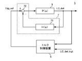
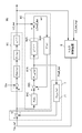
- the control device outputs a main signal (Tdy_ref) based on the output signal of the load cell (for example, torque control device 6 described later), and the natural vibration of the oscillator is suppressed.
- Natural vibration suppression means for example, natural vibration suppression circuit 7 to be described later that corrects the main signal and inputs it to the inverter as a control input signal (Tdy_ref ′), and the natural vibration suppression means outputs the output of the load cell.
- a differential compensator for example, differential compensator 71 described later for performing a differential operation on the signal (LC_det) or the approximate signal (Pmdl_det) of the load cell calculated using a predetermined approximate expression, and the differential compensation from the main signal
- a subtractor for example, a subtracter 72 described later
- the transfer function from the input to the inverter to the output of the load cell is approximately expressed by a second-order lag standard form.
- the control object can be damped so as to suppress the natural vibration of the oscillator.
- the natural vibration suppression means including such a differential compensator
- the natural vibration itself of the oscillator can be suppressed, and unnecessary torque fluctuation components can be removed from the output signal of the load cell. . Therefore, according to the present invention, a stable output signal can be obtained from the load cell without providing an acceleration sensor, which has been conventionally required, in the mechanical device.
- the main controller can control the dynamometer with stability and high response.
- the control device uses the sum of a control input signal input to the inverter or a signal proportional to the input and a predetermined feedback signal as an input, and determines from the input of the inverter to the output of the load cell.
- a vibration output calculation unit (for example, a vibration output calculation unit 81A described later) that outputs the approximate signal based on an approximate expression characterized by the damping coefficient of the oscillator and the natural frequency of the oscillator,
- a delay compensator for example, delay compensators 82A and 82B to be described later
- a dead time delay element for example, e ⁇ Lmdl ⁇ s to be described later
- the feedback to the vibration output calculator is minimized so that the deviation (err) from the output signal (LC_det) of the load cell is minimized.
- Deviation compensator which outputs a signal (e.g., deviation compensator 83A described later
- a vibration output calculation unit that outputs an approximate signal based on the approximate expression characterized by the natural frequency and damping coefficient of the oscillator is provided, and a predetermined dead time is provided by the delay compensator and the deviation compensator.
- the delay compensator includes the dead time delay element (for example, e ⁇ Lmdl ⁇ s described later) and a low-pass filter element for removing noise from the approximate signal (for example, PF_mdl (s) described later. )) are preferably connected.
- the system from the input of the inverter to the output of the load cell may be provided with a filter for removing high frequency noise.
- the delay compensator is configured by connecting a dead time delay element and a low-pass filter element, so that a phase advance compensation for the dead time and an approximate signal that compensates the actual load cell detection characteristic are obtained as a differential compensator. Can be entered. Thereby, the natural vibration of the oscillator can be more reliably suppressed.
- control device multiplies a control input signal input to the inverter by a predetermined coefficient (for example, a proportional element 84C described later), an output signal of the proportional element, and the feedback signal. It is preferable to further include an adder (for example, an adder 85C described later) that inputs the sum of the above to the vibration output calculation unit.
- a predetermined coefficient for example, a proportional element 84C described later
- an output signal of the proportional element and the feedback signal.
- an adder for example, an adder 85C described later
- a signal obtained by multiplying the control input signal by a predetermined coefficient may be input to the inverter in order to correct the DC gain characteristic to an appropriate one.
- the sum of the control input signal input to the inverter multiplied by a predetermined coefficient and the feedback signal is input to the vibration output calculation unit, so that the approximate signal considering the correction of the DC gain characteristic is differentiated. Can be input to the compensator. Thereby, the natural vibration of the oscillator can be more reliably suppressed.
- the approximate expression is defined by the transfer function P mdl (s) below, where ⁇ n is the natural frequency of the oscillator, ⁇ is a damping coefficient, s is a Laplace operator, and the differential
- the transfer function of the compensator is an arbitrary constant larger than 0 and smaller than 1
- 1 / G LPF (s) is an arbitrary transfer function having a relative degree of 1 or more, and has the following transfer function H LPF ( It is preferable to be defined by s).
- a closed loop transfer function G (s) of a system configured by feedback coupling of the above P mdl (s) and H LPF (s) is introduced to reduce detection noise in a high frequency range.
- G LPF (s) is approximately 1
- the following equation (2) is obtained. Therefore, according to the present invention, by adjusting the coefficient K of the differential compensator, a preferable frequency response characteristic can be easily realized so as to suppress the resonance point at the natural frequency.
- a stable output signal can be obtained from the load cell without providing an acceleration sensor in the mechanical device. Further, by suppressing the natural vibration of the oscillator by such natural vibration suppressing means, the main controller can control the dynamometer with stability and high response.
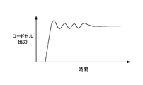
- FIG. 3 is a block diagram illustrating a configuration of a control device according to the first embodiment. It is a figure which shows the step response example of the transfer function from the input to an inverter to the output of a load cell. It is a Bode diagram of a closed loop transfer function. It is a block diagram which shows the structure of the control apparatus of Example 2. It is a block diagram which shows the structure of the control apparatus of Example 3.
- FIG. 10 is a block diagram illustrating a configuration of a control device according to a fourth embodiment.
- FIG. 10 is a block diagram illustrating a configuration of a control device according to a fifth embodiment.
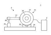
- FIG. 1 is a diagram schematically showing a configuration of a swing type dynamometer system 1.
- the system 1 includes an oscillating dynamometer 2, an inverter 3 that supplies power corresponding to a torque current command signal to the dynamometer 2, and a control device (not shown).
- a load (not shown) is connected to the rotating shaft of the rotor 22.
- the rocker 23 is provided with a torque arm 27 extending substantially horizontally.
- the load cell 26 is provided on the base 24. Further, the torque arm 27 and the load cell 26 are connected via a connecting member 28 provided at the tip of the torque arm 27.
- torque generated in the oscillators 23 is detected by the load cell 26 via the torque arm 27 and the connecting member 28.
- the transfer function of the differential compensator 71 is not limited to the transfer function H (s) having a complete differential characteristic as defined by the above equation (5-1).
- the transfer function of the differential compensator 71 uses a transfer function H LPF (s) having a pseudo differential characteristic as defined by the following equation (6) in order to reduce detection noise in a high frequency band. May be.
- the transfer function 1 / G LPF (s) is an arbitrary function having a relative degree of 1 or more.
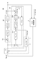
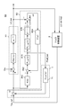
- FIG. 5 is a block diagram illustrating a configuration of a dynamometer control device 5A according to the second embodiment.
- the control device 5A according to the present embodiment is different from the control device 5 according to the first embodiment in that an observer calculation unit 8A is further provided.
- an observer calculation unit 8A is further provided.
- the same components as those of the control device 5 of the first embodiment are denoted by the same reference numerals, and the description thereof is omitted.
- the observer calculation unit 8A includes a vibration output calculation unit 81A, a delay compensator 82A, and a deviation compensator 83A.
- the vibration output calculation unit 81A receives a sum of a torque current command signal Tdy_ref ′ input to the inverter and a feedback signal to be described later output from the deviation compensator 83A as an input, and based on an approximate expression shown in the following expression (7).
- the approximate signal Pmdl_det is output.
- the approximate signal Pmdl_det output from the vibration output calculation unit 81A is input to the delay compensator 82A and the differential compensator 71.
- the delay compensator 82A includes a dead time delay element e ⁇ Lmdl ⁇ s that delays the approximate signal Pmdl_det by a predetermined dead time Lmdl.
- Deviation compensator 83A outputs a feedback signal so that deviation err obtained by subtracting load cell output signal LC_det from output signal LCmdl_det of delay compensator 82A is minimized.
- the transfer function F (s) of the deviation compensator 83A is, for example, as follows: a coefficient KG is an adjustment gain (0 ⁇ KG ⁇ 1), and 1 / F LPF (s) is an arbitrary transfer function having a relative degree of 1 or more. It is represented by Formula (8).
- the control object 9A has a delay corresponding to the dead time L.
- the differential compensator 71 has a load cell.
- An approximate signal Pmdl_det that has been compensated for the phase advance for the dead time can be input to the output LC_det.
- the delay compensator 82B of the observer computation unit 8B includes a dead time delay element e ⁇ Lmdl ⁇ s that delays the approximate signal Pmdl_det by a predetermined dead time Lmdl, and a low-pass filter element PF_mdl (s) that removes noise from the approximate signal Pmdl_det. , And connected.
- FIG. 7 is a block diagram illustrating a configuration of a control device 5C of the dynamometer system according to the fourth embodiment.
- the control device 5C of the present embodiment is different from the control device 5A of the second embodiment in the configuration of the observer calculation unit 8C.
- the same components as those of the control device 5A of the second embodiment are denoted by the same reference numerals and description thereof is omitted.
- the DC gain characteristic may be corrected in order to eliminate this deviation.
- the transfer function Pdc (s) from the input to the inverter to the output of the load cell is approximated by the following equation (9) instead of the above equation (3) by introducing the coefficient KC. Is done.
- the observer calculation unit 8C further includes a proportional element 84C that multiplies the control input signal Tdy_ref 'by the DC gain Kdc in order to compensate for this DC gain characteristic.
- the adder 85C inputs the sum of the output signal of the proportional element 84C and the feedback signal from the deviation compensator 83A to the vibration output calculation unit 81A.
- the control input signal Tdy_ref ′ multiplied by the DC gain Kdc is input to the vibration output calculation unit 81A, so that the approximate signal Pmdl_det subjected to the dead time phase advance compensation and the DC gain characteristic compensation is obtained as the differential compensator 71. Can be entered. Thereby, the natural vibration of the oscillator can be more reliably suppressed.
- FIG. 8 is a block diagram illustrating a configuration of a control device 5D of the dynamometer system according to the fifth embodiment.
- the control device 5D of the present embodiment is different from the control device 5C of the fourth embodiment in the configuration of the observer computation unit 8C.
- the same components as those of the control device 5C of the fourth embodiment are denoted by the same reference numerals, and the description thereof is omitted.
- the delay compensator 82B of the observer computation unit 8D includes a dead time delay element e ⁇ Lmdl ⁇ s that delays the approximate signal Pmdl_det by a predetermined dead time Lmdl, and a low-pass filter element PF_mdl (s) that removes noise from the approximate signal Pmdl_det. , And connected.
- the approximate signal Pmdl_det subjected to phase advance compensation for the dead time, actual load cell detection characteristic compensation, and DC gain characteristic compensation can be input to the differential compensator 71. Thereby, the natural vibration of the oscillator can be more reliably suppressed.
Landscapes
- Physics & Mathematics (AREA)
- General Physics & Mathematics (AREA)
- Control Of Electric Motors In General (AREA)
- Apparatuses For Generation Of Mechanical Vibrations (AREA)
Priority Applications (3)
| Application Number | Priority Date | Filing Date | Title |
|---|---|---|---|
| CN201380027761.XA CN104380067B (zh) | 2012-05-29 | 2013-05-28 | 测力计系统的控制装置 |
| KR1020147036138A KR101515902B1 (ko) | 2012-05-29 | 2013-05-28 | 다이나모미터 시스템의 제어장치 |
| US14/404,352 US9335228B2 (en) | 2012-05-29 | 2013-05-28 | Dynamometer system control device |
Applications Claiming Priority (2)
| Application Number | Priority Date | Filing Date | Title |
|---|---|---|---|
| JP2012-122378 | 2012-05-29 | ||
| JP2012122378A JP5541314B2 (ja) | 2012-05-29 | 2012-05-29 | ダイナモメータシステムの制御装置 |
Publications (1)
| Publication Number | Publication Date |
|---|---|
| WO2013180130A1 true WO2013180130A1 (ja) | 2013-12-05 |
Family
ID=49673322
Family Applications (1)
| Application Number | Title | Priority Date | Filing Date |
|---|---|---|---|
| PCT/JP2013/064771 WO2013180130A1 (ja) | 2012-05-29 | 2013-05-28 | ダイナモメータシステムの制御装置 |
Country Status (5)
| Country | Link |
|---|---|
| US (1) | US9335228B2 (ko) |
| JP (1) | JP5541314B2 (ko) |
| KR (1) | KR101515902B1 (ko) |
| CN (1) | CN104380067B (ko) |
| WO (1) | WO2013180130A1 (ko) |
Cited By (1)
| Publication number | Priority date | Publication date | Assignee | Title |
|---|---|---|---|---|
| CN107076643A (zh) * | 2014-09-30 | 2017-08-18 | 株式会社明电舍 | 测功机系统的控制装置 |
Families Citing this family (11)
| Publication number | Priority date | Publication date | Assignee | Title |
|---|---|---|---|---|
| JP5888371B2 (ja) | 2014-07-14 | 2016-03-22 | 株式会社明電舎 | 揺動式ダイナモメータシステム及びその制御方法 |
| KR101646129B1 (ko) | 2015-02-16 | 2016-08-05 | 현대자동차 주식회사 | 차량용 라디에이터 |
| CN106489105B (zh) * | 2015-06-18 | 2018-06-22 | 三菱电机株式会社 | 控制参数调整装置 |
| JP6629574B2 (ja) * | 2015-11-12 | 2020-01-15 | 株式会社エー・アンド・デイ | エンジン試験装置 |
| KR101897327B1 (ko) * | 2016-04-25 | 2018-09-11 | 국방과학연구소 | 힘 측정 센서 및 이에 의한 실시간 오프셋 제거 방법 |
| JP6226021B2 (ja) * | 2016-04-28 | 2017-11-08 | 株式会社明電舎 | 試験システムのダイナモメータ制御装置 |
| WO2018016628A1 (ja) * | 2016-07-22 | 2018-01-25 | 株式会社明電舎 | 軸トルク制御装置 |
| JP6497408B2 (ja) * | 2017-04-14 | 2019-04-10 | 株式会社明電舎 | 電気慣性制御装置 |
| JP6369596B1 (ja) | 2017-05-09 | 2018-08-08 | 株式会社明電舎 | ダイナモメータシステムの制御装置 |
| EP3489641B1 (en) * | 2017-11-27 | 2024-04-17 | Goodrich Actuation Systems Limited | Improved system for detecting a mechanical fault in a rotating shaft |
| JP6687086B1 (ja) * | 2018-11-07 | 2020-04-22 | 株式会社明電舎 | 電気慣性制御装置 |
Citations (4)
| Publication number | Priority date | Publication date | Assignee | Title |
|---|---|---|---|---|
| JP2798217B2 (ja) * | 1989-07-27 | 1998-09-17 | 三菱重工業株式会社 | 高速位置決め制御方法 |
| JP2008070119A (ja) * | 2006-09-12 | 2008-03-27 | Meidensha Corp | エンジンベンチシステムの制御方法とその装置 |
| JP2010019652A (ja) * | 2008-07-10 | 2010-01-28 | Meidensha Corp | エンジンベンチシステムの動力計制御方式 |
| JP2011161987A (ja) * | 2010-02-05 | 2011-08-25 | Nsk Ltd | 電動パワーステアリング装置 |
Family Cites Families (6)
| Publication number | Priority date | Publication date | Assignee | Title |
|---|---|---|---|---|
| JPS5857697B2 (ja) * | 1978-05-25 | 1983-12-21 | 株式会社小野測器 | 負荷制御方法及び装置 |
| JPS5890135A (ja) | 1981-11-26 | 1983-05-28 | Meidensha Electric Mfg Co Ltd | 動力計のトルク検出装置 |
| JPH01138836A (ja) | 1987-11-26 | 1989-05-31 | Mitsubishi Electric Corp | 端末制御方式 |
| US4963804A (en) * | 1989-07-10 | 1990-10-16 | Westinghouse Electric Corp. | Apparatus and method for reducing vibration of rotating machinery |
| JP4826088B2 (ja) | 2004-12-28 | 2011-11-30 | 株式会社明電舎 | 油圧浮揚式電気動力計 |
| EP2159554A1 (de) * | 2008-08-29 | 2010-03-03 | Mettler-Toledo AG | Verfahren zur Zustandsüberwachung einer Kraftmessvorrichtung, Kraftmessvorrichtung und Kraftmessmodul |
-
2012
- 2012-05-29 JP JP2012122378A patent/JP5541314B2/ja active Active
-
2013
- 2013-05-28 US US14/404,352 patent/US9335228B2/en active Active
- 2013-05-28 KR KR1020147036138A patent/KR101515902B1/ko active IP Right Grant
- 2013-05-28 CN CN201380027761.XA patent/CN104380067B/zh active Active
- 2013-05-28 WO PCT/JP2013/064771 patent/WO2013180130A1/ja active Application Filing
Patent Citations (4)
| Publication number | Priority date | Publication date | Assignee | Title |
|---|---|---|---|---|
| JP2798217B2 (ja) * | 1989-07-27 | 1998-09-17 | 三菱重工業株式会社 | 高速位置決め制御方法 |
| JP2008070119A (ja) * | 2006-09-12 | 2008-03-27 | Meidensha Corp | エンジンベンチシステムの制御方法とその装置 |
| JP2010019652A (ja) * | 2008-07-10 | 2010-01-28 | Meidensha Corp | エンジンベンチシステムの動力計制御方式 |
| JP2011161987A (ja) * | 2010-02-05 | 2011-08-25 | Nsk Ltd | 電動パワーステアリング装置 |
Cited By (2)
| Publication number | Priority date | Publication date | Assignee | Title |
|---|---|---|---|---|
| CN107076643A (zh) * | 2014-09-30 | 2017-08-18 | 株式会社明电舍 | 测功机系统的控制装置 |
| KR101784716B1 (ko) | 2014-09-30 | 2017-10-12 | 메이덴샤 코포레이션 | 다이나모미터 시스템의 제어 장치 |
Also Published As
| Publication number | Publication date |
|---|---|
| JP2013246152A (ja) | 2013-12-09 |
| KR20150023461A (ko) | 2015-03-05 |
| CN104380067B (zh) | 2016-01-20 |
| US9335228B2 (en) | 2016-05-10 |
| JP5541314B2 (ja) | 2014-07-09 |
| CN104380067A (zh) | 2015-02-25 |
| KR101515902B1 (ko) | 2015-05-04 |
| US20150219510A1 (en) | 2015-08-06 |
Similar Documents
| Publication | Publication Date | Title |
|---|---|---|
| JP5541314B2 (ja) | ダイナモメータシステムの制御装置 | |
| KR101525421B1 (ko) | 다이나모미터 시스템 | |
| EP0713287B1 (en) | Power system stabilizer for generator | |
| JP6584658B2 (ja) | 電動パワーステアリング装置 | |
| JP2010041734A (ja) | モータ制御装置 | |
| JPWO2007138758A1 (ja) | サーボ制御装置 | |
| WO2013129533A1 (ja) | ダイナモメータシステム | |
| WO2008075558A1 (ja) | 位置制御装置 | |
| KR101402873B1 (ko) | 전동기의 위치제어장치 | |
| JP2009042985A (ja) | モータ制御装置及びモータ制御方法 | |
| CN107408910B (zh) | 电动机控制装置以及搭载了该电动机控制装置的电动助力转向装置 | |
| US11669055B2 (en) | Vibration suppression device, method and computer-readable medium using estimated vibration torque | |
| JP2011257205A (ja) | ダイナモメータシステムの軸トルク制御装置 | |
| JP2015170208A (ja) | 制御装置、制御方法及び制御プログラム | |
| JP2005085074A (ja) | 位置制御装置 | |
| WO2018207832A1 (ja) | ダイナモメータシステムの制御装置 | |
| JP2010019713A (ja) | 動力計システムの電気慣性制御装置 | |
| JP5017984B2 (ja) | サーボ制御装置とその速度追従制御方法 | |
| JP2011160574A (ja) | 電動機の速度制御装置 | |
| JPWO2018179043A1 (ja) | 電動パワーステアリング装置 | |
| WO2014129168A1 (ja) | 空間安定装置、空間安定方法、及び空間安定プログラム記憶媒体 | |
| JPWO2008072574A1 (ja) | 交流電動機の制御装置 | |
| JP5084196B2 (ja) | 電動機制御装置および電動機制御方法 | |
| WO2020235130A1 (ja) | モータ駆動装置及びモータ駆動装置の制御方法 | |
| JPH11155295A (ja) | 制振制御装置 |
Legal Events
| Date | Code | Title | Description |
|---|---|---|---|
| 121 | Ep: the epo has been informed by wipo that ep was designated in this application |
Ref document number: 13797299 Country of ref document: EP Kind code of ref document: A1 |
|
| WWE | Wipo information: entry into national phase |
Ref document number: 14404352 Country of ref document: US |
|
| NENP | Non-entry into the national phase |
Ref country code: DE |
|
| ENP | Entry into the national phase |
Ref document number: 20147036138 Country of ref document: KR Kind code of ref document: A |
|
| 122 | Ep: pct application non-entry in european phase |
Ref document number: 13797299 Country of ref document: EP Kind code of ref document: A1 |