WO2013179334A1 - 空気調和装置 - Google Patents
空気調和装置 Download PDFInfo
- Publication number
- WO2013179334A1 WO2013179334A1 PCT/JP2012/003515 JP2012003515W WO2013179334A1 WO 2013179334 A1 WO2013179334 A1 WO 2013179334A1 JP 2012003515 W JP2012003515 W JP 2012003515W WO 2013179334 A1 WO2013179334 A1 WO 2013179334A1
- Authority
- WO
- WIPO (PCT)
- Prior art keywords
- refrigerant
- side unit
- load
- heat source
- heat exchanger
- Prior art date
Links
Images


Classifications
-
- F—MECHANICAL ENGINEERING; LIGHTING; HEATING; WEAPONS; BLASTING
- F25—REFRIGERATION OR COOLING; COMBINED HEATING AND REFRIGERATION SYSTEMS; HEAT PUMP SYSTEMS; MANUFACTURE OR STORAGE OF ICE; LIQUEFACTION SOLIDIFICATION OF GASES
- F25B—REFRIGERATION MACHINES, PLANTS OR SYSTEMS; COMBINED HEATING AND REFRIGERATION SYSTEMS; HEAT PUMP SYSTEMS
- F25B29/00—Combined heating and refrigeration systems, e.g. operating alternately or simultaneously
- F25B29/003—Combined heating and refrigeration systems, e.g. operating alternately or simultaneously of the compression type system
-
- F—MECHANICAL ENGINEERING; LIGHTING; HEATING; WEAPONS; BLASTING
- F25—REFRIGERATION OR COOLING; COMBINED HEATING AND REFRIGERATION SYSTEMS; HEAT PUMP SYSTEMS; MANUFACTURE OR STORAGE OF ICE; LIQUEFACTION SOLIDIFICATION OF GASES
- F25B—REFRIGERATION MACHINES, PLANTS OR SYSTEMS; COMBINED HEATING AND REFRIGERATION SYSTEMS; HEAT PUMP SYSTEMS
- F25B41/00—Fluid-circulation arrangements
- F25B41/20—Disposition of valves, e.g. of on-off valves or flow control valves
- F25B41/22—Disposition of valves, e.g. of on-off valves or flow control valves between evaporator and compressor
-
- F—MECHANICAL ENGINEERING; LIGHTING; HEATING; WEAPONS; BLASTING
- F24—HEATING; RANGES; VENTILATING
- F24F—AIR-CONDITIONING; AIR-HUMIDIFICATION; VENTILATION; USE OF AIR CURRENTS FOR SCREENING
- F24F11/00—Control or safety arrangements
- F24F11/30—Control or safety arrangements for purposes related to the operation of the system, e.g. for safety or monitoring
-
- F—MECHANICAL ENGINEERING; LIGHTING; HEATING; WEAPONS; BLASTING
- F24—HEATING; RANGES; VENTILATING
- F24F—AIR-CONDITIONING; AIR-HUMIDIFICATION; VENTILATION; USE OF AIR CURRENTS FOR SCREENING
- F24F11/00—Control or safety arrangements
- F24F11/62—Control or safety arrangements characterised by the type of control or by internal processing, e.g. using fuzzy logic, adaptive control or estimation of values
-
- F—MECHANICAL ENGINEERING; LIGHTING; HEATING; WEAPONS; BLASTING
- F25—REFRIGERATION OR COOLING; COMBINED HEATING AND REFRIGERATION SYSTEMS; HEAT PUMP SYSTEMS; MANUFACTURE OR STORAGE OF ICE; LIQUEFACTION SOLIDIFICATION OF GASES
- F25B—REFRIGERATION MACHINES, PLANTS OR SYSTEMS; COMBINED HEATING AND REFRIGERATION SYSTEMS; HEAT PUMP SYSTEMS
- F25B13/00—Compression machines, plants or systems, with reversible cycle
-
- F—MECHANICAL ENGINEERING; LIGHTING; HEATING; WEAPONS; BLASTING
- F25—REFRIGERATION OR COOLING; COMBINED HEATING AND REFRIGERATION SYSTEMS; HEAT PUMP SYSTEMS; MANUFACTURE OR STORAGE OF ICE; LIQUEFACTION SOLIDIFICATION OF GASES
- F25B—REFRIGERATION MACHINES, PLANTS OR SYSTEMS; COMBINED HEATING AND REFRIGERATION SYSTEMS; HEAT PUMP SYSTEMS
- F25B30/00—Heat pumps
- F25B30/02—Heat pumps of the compression type
-
- F—MECHANICAL ENGINEERING; LIGHTING; HEATING; WEAPONS; BLASTING
- F25—REFRIGERATION OR COOLING; COMBINED HEATING AND REFRIGERATION SYSTEMS; HEAT PUMP SYSTEMS; MANUFACTURE OR STORAGE OF ICE; LIQUEFACTION SOLIDIFICATION OF GASES
- F25B—REFRIGERATION MACHINES, PLANTS OR SYSTEMS; COMBINED HEATING AND REFRIGERATION SYSTEMS; HEAT PUMP SYSTEMS
- F25B49/00—Arrangement or mounting of control or safety devices
- F25B49/02—Arrangement or mounting of control or safety devices for compression type machines, plants or systems
-
- F—MECHANICAL ENGINEERING; LIGHTING; HEATING; WEAPONS; BLASTING
- F24—HEATING; RANGES; VENTILATING
- F24F—AIR-CONDITIONING; AIR-HUMIDIFICATION; VENTILATION; USE OF AIR CURRENTS FOR SCREENING
- F24F11/00—Control or safety arrangements
- F24F11/30—Control or safety arrangements for purposes related to the operation of the system, e.g. for safety or monitoring
- F24F11/41—Defrosting; Preventing freezing
- F24F11/42—Defrosting; Preventing freezing of outdoor units
-
- F—MECHANICAL ENGINEERING; LIGHTING; HEATING; WEAPONS; BLASTING
- F24—HEATING; RANGES; VENTILATING
- F24F—AIR-CONDITIONING; AIR-HUMIDIFICATION; VENTILATION; USE OF AIR CURRENTS FOR SCREENING
- F24F2221/00—Details or features not otherwise provided for
- F24F2221/54—Heating and cooling, simultaneously or alternatively
-
- F—MECHANICAL ENGINEERING; LIGHTING; HEATING; WEAPONS; BLASTING
- F25—REFRIGERATION OR COOLING; COMBINED HEATING AND REFRIGERATION SYSTEMS; HEAT PUMP SYSTEMS; MANUFACTURE OR STORAGE OF ICE; LIQUEFACTION SOLIDIFICATION OF GASES
- F25B—REFRIGERATION MACHINES, PLANTS OR SYSTEMS; COMBINED HEATING AND REFRIGERATION SYSTEMS; HEAT PUMP SYSTEMS
- F25B2313/00—Compression machines, plants or systems with reversible cycle not otherwise provided for
- F25B2313/006—Compression machines, plants or systems with reversible cycle not otherwise provided for two pipes connecting the outdoor side to the indoor side with multiple indoor units
-
- F—MECHANICAL ENGINEERING; LIGHTING; HEATING; WEAPONS; BLASTING
- F25—REFRIGERATION OR COOLING; COMBINED HEATING AND REFRIGERATION SYSTEMS; HEAT PUMP SYSTEMS; MANUFACTURE OR STORAGE OF ICE; LIQUEFACTION SOLIDIFICATION OF GASES
- F25B—REFRIGERATION MACHINES, PLANTS OR SYSTEMS; COMBINED HEATING AND REFRIGERATION SYSTEMS; HEAT PUMP SYSTEMS
- F25B2313/00—Compression machines, plants or systems with reversible cycle not otherwise provided for
- F25B2313/023—Compression machines, plants or systems with reversible cycle not otherwise provided for using multiple indoor units
- F25B2313/0231—Compression machines, plants or systems with reversible cycle not otherwise provided for using multiple indoor units with simultaneous cooling and heating
-
- F—MECHANICAL ENGINEERING; LIGHTING; HEATING; WEAPONS; BLASTING
- F25—REFRIGERATION OR COOLING; COMBINED HEATING AND REFRIGERATION SYSTEMS; HEAT PUMP SYSTEMS; MANUFACTURE OR STORAGE OF ICE; LIQUEFACTION SOLIDIFICATION OF GASES
- F25B—REFRIGERATION MACHINES, PLANTS OR SYSTEMS; COMBINED HEATING AND REFRIGERATION SYSTEMS; HEAT PUMP SYSTEMS
- F25B2313/00—Compression machines, plants or systems with reversible cycle not otherwise provided for
- F25B2313/023—Compression machines, plants or systems with reversible cycle not otherwise provided for using multiple indoor units
- F25B2313/0233—Compression machines, plants or systems with reversible cycle not otherwise provided for using multiple indoor units in parallel arrangements
-
- F—MECHANICAL ENGINEERING; LIGHTING; HEATING; WEAPONS; BLASTING
- F25—REFRIGERATION OR COOLING; COMBINED HEATING AND REFRIGERATION SYSTEMS; HEAT PUMP SYSTEMS; MANUFACTURE OR STORAGE OF ICE; LIQUEFACTION SOLIDIFICATION OF GASES
- F25B—REFRIGERATION MACHINES, PLANTS OR SYSTEMS; COMBINED HEATING AND REFRIGERATION SYSTEMS; HEAT PUMP SYSTEMS
- F25B2313/00—Compression machines, plants or systems with reversible cycle not otherwise provided for
- F25B2313/027—Compression machines, plants or systems with reversible cycle not otherwise provided for characterised by the reversing means
- F25B2313/0272—Compression machines, plants or systems with reversible cycle not otherwise provided for characterised by the reversing means using bridge circuits of one-way valves
-
- F—MECHANICAL ENGINEERING; LIGHTING; HEATING; WEAPONS; BLASTING
- F25—REFRIGERATION OR COOLING; COMBINED HEATING AND REFRIGERATION SYSTEMS; HEAT PUMP SYSTEMS; MANUFACTURE OR STORAGE OF ICE; LIQUEFACTION SOLIDIFICATION OF GASES
- F25B—REFRIGERATION MACHINES, PLANTS OR SYSTEMS; COMBINED HEATING AND REFRIGERATION SYSTEMS; HEAT PUMP SYSTEMS
- F25B2313/00—Compression machines, plants or systems with reversible cycle not otherwise provided for
- F25B2313/027—Compression machines, plants or systems with reversible cycle not otherwise provided for characterised by the reversing means
- F25B2313/02741—Compression machines, plants or systems with reversible cycle not otherwise provided for characterised by the reversing means using one four-way valve
-
- F—MECHANICAL ENGINEERING; LIGHTING; HEATING; WEAPONS; BLASTING
- F25—REFRIGERATION OR COOLING; COMBINED HEATING AND REFRIGERATION SYSTEMS; HEAT PUMP SYSTEMS; MANUFACTURE OR STORAGE OF ICE; LIQUEFACTION SOLIDIFICATION OF GASES
- F25B—REFRIGERATION MACHINES, PLANTS OR SYSTEMS; COMBINED HEATING AND REFRIGERATION SYSTEMS; HEAT PUMP SYSTEMS
- F25B2313/00—Compression machines, plants or systems with reversible cycle not otherwise provided for
- F25B2313/029—Control issues
- F25B2313/0292—Control issues related to reversing valves
-
- F—MECHANICAL ENGINEERING; LIGHTING; HEATING; WEAPONS; BLASTING
- F25—REFRIGERATION OR COOLING; COMBINED HEATING AND REFRIGERATION SYSTEMS; HEAT PUMP SYSTEMS; MANUFACTURE OR STORAGE OF ICE; LIQUEFACTION SOLIDIFICATION OF GASES
- F25B—REFRIGERATION MACHINES, PLANTS OR SYSTEMS; COMBINED HEATING AND REFRIGERATION SYSTEMS; HEAT PUMP SYSTEMS
- F25B2600/00—Control issues
- F25B2600/25—Control of valves
- F25B2600/2513—Expansion valves
Definitions
- the present invention relates to an air conditioner capable of performing a cooling operation or a heating operation (hereinafter referred to as cooling and heating mixed operation) in each of a plurality of indoor units (load side units), and particularly in a cooling and heating mixed operation in low outside air. It is related with the air conditioning apparatus which suppressed the fall of the capability of this and improved the stability of driving
- an air conditioner that can perform a cooling and heating mixed operation (see, for example, Patent Document 1).
- Such an air conditioner determines whether to operate the load side unit in the cooling cycle or the heating cycle in accordance with the air condition and the operating load.
- Such an air conditioner selects an appropriate refrigeration cycle according to the load, and realizes a cooling and heating mixed operation.
- antifreezing control In order to prevent such a situation in advance, when the liquid pipe temperature of the load side unit falls below a predetermined temperature, the operation of the load side unit is forcibly stopped (hereinafter referred to as antifreezing control). Already exists. However, when anti-freezing control is executed, the load-side unit that is in the heating operation continues to operate, but the load-side unit that is in the cooling operation is forcibly stopped. 0. During this time, there was a problem that the user's comfort was lowered. In addition, by repeating the stop and start, there is a problem that the operation state becomes unstable and the ability cannot be continuously exhibited.
- the present invention has been made to solve the above-described problems, and suppresses a decrease in capability during mixed cooling / heating operation in low outside air without performing anti-freezing control, thereby improving operational stability.
- An object of the present invention is to provide an air conditioning apparatus.
- An air conditioner includes at least one heat source side unit on which a compressor and an outdoor heat exchanger are mounted, and is connected in parallel to the heat source side unit, and includes an expansion device and an indoor heat exchanger.
- a plurality of load-side units connected to each other and capable of simultaneous cooling and heating operation, the air-conditioning device being mounted on the heat-source-side unit, and flowing the refrigerant from the load-side unit to the outdoor heat exchanger.
- control device is in a warm main operation mode in which there are many heating loads during simultaneous cooling and heating operations by the plurality of load side units, and the liquid pipe temperature of the load side unit performing the cooling operation is prevented from freezing.
- the on-off valve is closed, the opening degree of the heat source side expansion device is controlled in accordance with the evaporation temperature of the load side unit required for cooling, and the evaporation temperature is kept within a predetermined range. It is characterized by adjusting to.
- the liquid pipe temperature of the load side unit can be controlled within an appropriate range by the opening degree of the heat source side expansion device, particularly during the warm main operation mode during the cooling and heating mixed operation. Without performing anti-freezing control, it is possible to suppress a decrease in capacity during cooling and heating mixed operation in low outside air, and to improve driving stability.
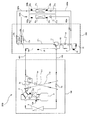
- FIG. 1 is a schematic configuration diagram illustrating an example of a refrigerant circuit configuration of an air-conditioning apparatus 500 according to an embodiment of the present invention. Based on FIG. 1, the refrigerant circuit structure of the air conditioning apparatus 500 is demonstrated.
- the air conditioner 500 is installed in, for example, a building or a condominium, and can perform a cooling and heating mixed operation using a refrigeration cycle (heat pump cycle) for circulating a refrigerant.
- a refrigeration cycle heat pump cycle
- the air conditioner 500 includes a heat source side unit 100, a plurality of (two in FIG. 1) load side units 300 (load side units 300a and 300b), and a refrigerant control unit 200.
- the refrigerant control unit 200 is installed between the heat source side unit 100 and the load side unit 300, and performs a cooling operation or a heating operation in each of the load side units 300 by switching the flow of the refrigerant. .
- the heat source side unit 100 and the refrigerant control unit 200 are two pipes (high pressure pipe 402, low pressure pipe 401), and the refrigerant control unit 200 and the load side unit 300 are two pipes (liquid A pipe 404 (liquid pipes 404a and 404b) and a gas pipe 403 (gas pipes 403a and 403b) are connected to form a refrigeration cycle.
- the heat source side unit 100 has a function of supplying cold or warm heat to the load side unit 300.
- a compressor 1, a four-way switching valve 2, which is a flow path switching means, an outdoor heat exchanger 3, and an accumulator 4 are connected in series to constitute a main refrigerant circuit. It is installed. Further, the heat source side unit 100 has a check valve 5a, a check valve 5b, so that the flow of the refrigerant flowing into the refrigerant control unit 200 can be in a certain direction regardless of the request of the load side unit 300. A check valve 5c, a check valve 5d, a first connection pipe 110, and a second connection pipe 111 are mounted. Further, the heat source side unit 100 is equipped with a throttle device (heat source side throttle device) 6 and an on-off valve 7.
- a throttle device heat source side throttle device
- the compressor 1 sucks a low-temperature / low-pressure gas refrigerant, compresses the refrigerant into a high-temperature / high-pressure gas refrigerant, and circulates the refrigerant in the system to perform an air-conditioning operation.
- the compressor 1 may be composed of, for example, an inverter type compressor capable of capacity control.
- the compressor 1 is not limited to an inverter type compressor capable of capacity control, and may be a constant speed type compressor or a compressor combined with an inverter type and a constant speed type.
- the four-way switching valve 2 is provided on the discharge side of the compressor 1 and switches the refrigerant flow path between the cooling operation and the heating operation.
- the outdoor heat exchanger 3 is an evaporator or a condenser depending on the operation mode. The flow of the refrigerant is controlled so as to function as
- the outdoor heat exchanger 3 performs heat exchange between a heat medium (for example, ambient air and water) and a refrigerant, evaporates and gasifies the refrigerant as an evaporator during heating operation, and a condenser (heat radiator) during cooling operation. ) To condense and liquefy the refrigerant.
- the outdoor heat exchanger 3 is generally configured as a fan not shown in the figure, and the condensing capacity or evaporating capacity is controlled by the rotational speed of the fan.
- the accumulator 4 is provided on the suction side of the compressor 1 and has a function of storing surplus refrigerant and a function of separating liquid refrigerant and gas refrigerant.
- the first connection pipe 110 connects the high pressure pipe 402 on the downstream side of the check valve 5a and the low pressure pipe 401 on the downstream side of the check valve 5b.
- the second connection pipe 111 connects the high pressure pipe 402 on the upstream side of the check valve 5a and the low pressure pipe 401 on the upstream side of the check valve 5b.
- the junction part of the 2nd connection piping 111 and the high-pressure piping 402 is the junction part a
- the junction part of the 1st connection pipe 110 and the high-pressure piping 402 is the junction part b (downstream from the junction part a)
- the 2nd connection pipe 111 is shown as a joining part c
- a joining part between the first connection pipe 110 and the low-pressure pipe 401 is shown as a joining part d (downstream from the joining part c).
- the check valve 5b is provided between the junction c and the junction d, and allows the refrigerant to flow only in the direction from the refrigerant control unit 200 to the heat source unit 100.
- the check valve 5 a is provided between the merging portion a and the merging portion b, and allows the refrigerant to flow only in the direction from the heat source side unit 100 to the refrigerant control unit 200.
- the check valve 5c is provided in the first connection pipe 110 and allows the refrigerant to flow only in the direction from the merging portion d to the merging portion b.
- the check valve 5d is provided in the second connection pipe 111 and allows the refrigerant to flow only from the junction c to the junction a.
- the on-off valve 7 is provided in the heat source side unit 100 upstream of the outdoor heat exchanger 3 (in the figure, the second connection pipe 111 on the upstream side of the check valve 5d), and the opening / closing is controlled to control the refrigerant. It may or may not conduct. That is, the on-off valve 7 adjusts the refrigerant flow from the refrigerant control unit 200 to the outdoor heat exchanger 3 by controlling the opening and closing.
- the expansion device 6 is provided in parallel with the on-off valve 7 and adjusts the refrigerant flow rate by controlling the opening degree. That is, the expansion device 6 adjusts the load side piping temperature, specifically, the evaporation temperature of the indoor heat exchanger 22 (indoor heat exchangers 22a and 22b) to an arbitrary range by controlling the opening degree.
- the heat source unit 100 includes a high-pressure sensor 131 that detects the pressure of the refrigerant discharged from the compressor 1, a low-pressure sensor 132 that detects the pressure of the refrigerant sucked into the compressor 1, and the refrigerant discharged from the compressor 1. At least a discharge temperature sensor 133 that detects the temperature and an inflow pipe temperature sensor 134 that detects the temperature of the refrigerant flowing into the accumulator 4 are provided. Information (temperature information and pressure information) detected by these various detection means is sent to the control device 8 that controls the operation of the air conditioner 500, and the drive frequency of the compressor 1 and the rotational speed of the blower (not shown). This is used for switching the four-way switching valve 2, opening / closing the opening / closing valve 7, and controlling the opening degree of the expansion device 6.
- the refrigerant control unit 200 is interposed between the heat source side unit 100 and the load side unit 300, and switches the flow of the refrigerant according to the operation state of the load side unit 300.
- “a” or “b” is added after the reference numerals of some devices included in the “refrigerant control unit 200”. This indicates whether it is connected to “load side unit 300a” described later or “load side unit 300b”.
- “a” and “b” added after the reference may be omitted. In this case, any of the “load-side unit 300a” or “load-side unit 300b” is connected. Needless to say, the explanation also includes the equipment.
- the refrigerant control unit 200 is connected to each of the heat source side units 100 by a high pressure pipe 402 and a low pressure pipe 401, and is connected to each of the load side units 300 by a liquid pipe 404 and a gas pipe 403.
- the refrigerant control unit 200 includes a gas-liquid separator 11, a first on-off valve 12 (first on-off valves 12a and 12b), a second on-off valve 13 (second on-off valves 13a and 13b), and a first throttle device. 14, a second expansion device 15, a first refrigerant heat exchanger 16, and a second refrigerant heat exchanger 17 are mounted.
- the refrigerant control unit 200 has a pipe branched on the downstream side of the primary side of the second refrigerant heat exchanger 17 (the side through which the refrigerant flows via the first expansion device 14) and connected to the low-pressure pipe 401.
- a pipe 120 is provided.
- the gas-liquid separator 11 is provided in the high-pressure pipe 402 and has a function of separating the two-phase refrigerant flowing through the high-pressure pipe 402 into a gas refrigerant and a liquid refrigerant.
- the gas refrigerant separated by the gas-liquid separator 11 is supplied to the first on-off valve 12 via the connection pipe 121, and the liquid refrigerant is supplied to the first refrigerant heat exchanger 16.
- the first on-off valve 12 is for controlling the supply of the refrigerant to the load side unit 300 for each operation mode, and is provided between the connection pipe 121 and the gas pipe 403. That is, one of the first on-off valves 12 is connected to the gas-liquid separator 11 and the other is connected to the indoor heat exchanger 22 of the load-side unit 300. Or not.
- the second on-off valve 13 is also for controlling the supply of the refrigerant to the load side unit 300 for each operation mode, and is provided between the gas pipe 403 and the low-pressure pipe 401.
- one of the second on-off valves 13 is connected to the low-pressure pipe 401 and the other is connected to the indoor heat exchanger 22 of the load-side unit 300. There is nothing to do.
- the first expansion device 14 is provided between a pipe connecting the gas-liquid separator 11 and the liquid pipe 404, that is, between the first refrigerant heat exchanger 16 and the second refrigerant heat exchanger 17, and includes a pressure reducing valve, It functions as an expansion valve, and expands the refrigerant by decompressing it.
- the first throttle device 14 may be configured by a device whose opening degree can be variably controlled, for example, a precise flow rate control device using an electronic expansion valve, an inexpensive refrigerant flow rate control means such as a capillary tube, or the like.
- the second expansion device 15 is provided on the upstream side of the secondary refrigerant heat exchanger 17 in the connection pipe 120 and has a function as a pressure reducing valve or an expansion valve, and decompresses and expands the refrigerant. Is. Similar to the first throttle device 14, the second throttle device 15 can be variably controlled in opening, for example, a precise flow control device using an electronic expansion valve, an inexpensive refrigerant flow rate control means such as a capillary tube, etc. It is good to comprise.
- the first refrigerant heat exchanger 16 includes a refrigerant flowing on the primary side (the side on which the liquid refrigerant separated by the gas-liquid separator 11 flows) and the secondary side (after passing through the second expansion device 15 in the connection pipe 120). (2) Heat exchange is performed between the refrigerant flowing through the refrigerant heat exchanger 17 and the refrigerant flowing through the refrigerant flow side.
- the second refrigerant heat exchanger 17 exchanges heat between the refrigerant flowing on the primary side (downstream side of the first expansion device 14) and the refrigerant flowing on the secondary side (downstream side of the second expansion device 15). It is something to execute.
- the first expansion device 14 By mounting the first expansion device 14, the second expansion device 15, the first refrigerant heat exchanger 16 and the second refrigerant heat exchanger 17 in the refrigerant control unit 200, the first refrigerant heat exchanger 16 and the second refrigerant heat
- the exchanger 17 exchanges heat between the refrigerant flowing through the main circuit (primary side) and the refrigerant flowing through the connection pipe 120 (secondary side) so that the refrigerant flowing through the main circuit can be supercooled.
- the amount of bypass is controlled so that proper subcooling can be achieved at the primary outlet of the second refrigerant heat exchanger 17 depending on the opening of the second expansion device 15.
- the refrigerant control unit 200 includes a temperature sensor 18 that detects the temperature of the refrigerant pipe (connection pipe 120) between the second expansion device 15 and the secondary inlet of the second refrigerant heat exchanger 17, and first refrigerant heat exchange. At least a temperature sensor 19 for detecting the temperature of the connecting pipe 120 downstream of the secondary side of the vessel 16 is provided. Information (temperature information) detected by these various detection means is sent to the control device 8 that controls the operation of the air conditioner 500, and is used to control various actuators.
- the information from the temperature sensor 18 and the temperature sensor 19 includes opening / closing of the on-off valves (the first on-off valve 12 and the second on-off valve 13) provided in the refrigerant control unit 200, and the respective throttle devices (first throttle device 14).
- the second opening device 15) is used for controlling the opening degree and the like.
- the load side unit 300 receives a supply of cold or warm heat from the heat source side unit 100 and takes charge of a cooling load or a heating load.
- “a” is added after the code of each device provided in the “load side unit 300 a”
- “b” is added after the code of each device provided in the “load side unit 300 b”. This is shown in the figure.
- “a” and “b” after the reference may be omitted, but it goes without saying that both the load-side unit 300a and the load-side unit 300b are equipped with each device. Yes.
- the load-side unit 300 includes an indoor heat exchanger 22 (indoor heat exchangers 22a and 22b) and an indoor expansion device 21 (indoor expansion devices 21a and 21b) connected in series.
- a blower (not shown) for supplying air to the indoor heat exchanger 22 may be provided.
- the indoor heat exchanger 22 may perform heat exchange between the refrigerant and a heat medium different from the refrigerant such as water.
- the indoor heat exchanger 22 performs heat exchange between a heat medium (for example, ambient air or water) and the refrigerant, condenses and liquefies the refrigerant as a condenser (heat radiator) during heating operation, and evaporates during cooling operation. As a vessel, the refrigerant is evaporated and gasified.
- the indoor heat exchanger 22 is generally configured by combining fans not shown in the figure, and the condensation capacity or evaporation capacity is controlled by the rotational speed of the fan.
- the indoor throttle device 21 has a function as a pressure reducing valve or an expansion valve, and expands the refrigerant by decompressing it.
- the indoor throttling device 21 may be configured by a device whose opening degree can be variably controlled, for example, a precise flow rate control device using an electronic expansion valve, an inexpensive refrigerant flow rate control means such as a capillary tube, or the like.
- the load unit 300 includes a temperature sensor 24 (temperature sensors 24 a and 24 b) that detects the temperature of the refrigerant pipe between the indoor expansion device 21 and the indoor heat exchanger 22, the indoor heat exchanger 22, and the first on-off valve 12. And the temperature sensor 23 (temperature sensor 23a, 23b) which detects the temperature of the refrigerant
- the compressor 1 is not particularly limited as long as it can compress the sucked refrigerant into a high pressure state.
- the compressor 1 can be configured using various types such as reciprocating, rotary, scroll, or screw.
- the type of refrigerant used in the air conditioner 500 is not particularly limited.
- natural refrigerants such as carbon dioxide, hydrocarbons and helium, alternative refrigerants not containing chlorine such as HFC410A, HFC407C, and HFC404A, or existing refrigerants Any of chlorofluorocarbon refrigerants such as R22 and R134a used in products may be used.
- FIG. 1 shows an example in which the control device 8 that controls the operation of the air conditioning apparatus 500 is mounted in the heat source side unit 100, it is provided in either the refrigerant control unit 200 or the load side unit 300. It may be. Further, the control device 8 may be provided outside the heat source side unit 100, the refrigerant control unit 200, and the load side unit 300. Further, the control device 8 may be divided into a plurality according to the function and provided in each of the heat source side unit 100, the refrigerant control unit 200, and the load side unit 300. In this case, each control device is preferably connected wirelessly or by wire so that communication is possible.
- an operation operation performed by the air conditioner 500 will be described.
- a cooling operation request and a heating operation request from a remote controller installed indoors are received and air conditioning operation is performed, and there are four operation modes according to these requests.
- the four operation modes it is determined that all the load side units 300 are all cooling operation modes that are cooling operation requests, cooling operation requests and heating operation requests are mixed, and there are many loads to be processed by the cooling operation. Cooling main operation mode, the cooling operation request and the heating operation request are mixed, and the warm main operation mode in which it is determined that the load to be processed by the heating operation is large. There is a warm-up mode that is.
- FIG. 2 is a refrigerant circuit diagram illustrating a refrigerant flow when the air-conditioning apparatus 500 is in the warm-up operation mode. Based on FIG. 2, the operation
- a low temperature / low pressure refrigerant is compressed by the compressor 1 and discharged as a high temperature / high pressure gas refrigerant.
- the high-temperature and high-pressure gas refrigerant discharged from the compressor 1 passes through the four-way switching valve 2 and flows to the high-pressure pipe 402 via the check valve 5c. Thereafter, the refrigerant flows out from the heat source unit 100.
- the high-temperature and high-pressure gas refrigerant that has flowed out of the heat source unit 100 passes through the gas-liquid separator 11 of the refrigerant control unit 200, passes through the connection pipe 121, and reaches the first on-off valve 12.
- the first on-off valve 12 is opened, the second on-off valve 13 is closed, and the high-temperature and high-pressure gas refrigerant reaches the load-side unit 300 through the gas pipe 403.
- the gas refrigerant that has flowed into the load-side unit 300 flows into the indoor heat exchanger 22 (the indoor heat exchanger 22a and the indoor heat exchanger 22b). Since the indoor heat exchanger 22 works as a condenser, the refrigerant is condensed and liquefied by exchanging heat with the surrounding air. At this time, the refrigerant radiates heat to the surroundings to heat the air-conditioning target space such as the room. Thereafter, the liquid refrigerant flowing out from the indoor heat exchanger 22 is decompressed by the indoor expansion device 21 (the indoor expansion device 21a and the indoor expansion device 21b) and flows out from the load side unit 300.
- the liquid refrigerant decompressed by the indoor expansion device 21 flows through the liquid pipe 404 (liquid pipe 404a and liquid pipe 404b) and flows into the refrigerant control unit 200.
- the liquid refrigerant that has flowed into the refrigerant control unit 200 reaches the low-pressure pipe 401 via the second throttle device 15 and the connection pipe 120.
- the refrigerant flowing through the low-pressure pipe 401 flows out of the refrigerant control unit 200 and then returns to the heat source side unit 100.
- the on-off valve 7 is open and the expansion device 6 is closed.
- the refrigerant that has returned to the heat source side unit 100 reaches the outdoor heat exchanger 3 via the on-off valve 7 and the check valve 5d. Since the outdoor heat exchanger 3 functions as an evaporator, the refrigerant exchanges heat with the surrounding air, and the refrigerant evaporates and gasifies. Thereafter, the refrigerant flowing out of the outdoor heat exchanger 3 flows into the accumulator 4 via the four-way switching valve 2.
- the refrigerant in the accumulator 4 is sucked by the compressor 1 and circulated in the system, so that a refrigeration cycle is established.
- the air conditioner 500 executes the heating only operation mode.
- the operation mode in the warm main operation mode It becomes.
- FIG. 3 is a refrigerant circuit diagram illustrating a refrigerant flow when the air-conditioning apparatus 500 is in the warm main operation mode. Based on FIG. 3, the operation
- the warm main operation mode when there is a heating request from the load side unit 300a and a cooling request from the load side unit 300b will be described.
- requirement is the same as the time of a warming-up mode, description is abbreviate
- the liquid refrigerant that has passed through the liquid pipe 404a is supercooled by the second refrigerant heat exchanger 17, and reaches the load-side unit 300b that requires cooling through the liquid pipe 404b.
- the refrigerant flowing into the load side unit 300b is decompressed by the indoor expansion device 21b.
- the refrigerant decompressed by the indoor expansion device 21b flows into the indoor heat exchanger 22b. Since the indoor heat exchanger 22b serves as an evaporator, the refrigerant evaporates and gasifies by exchanging heat with the surrounding air. At this time, the refrigerant cools the room by absorbing heat from the surroundings.
- the refrigerant that has flowed out of the load-side unit 300b flows through the connection pipe 120 via the second on-off valve 13b.
- This refrigerant merges with the refrigerant that has flowed through the connection pipe 120 via the first throttling device 14 and the second throttling device 15 for supercooling by the second refrigerant heat exchanger 17, and reaches the low-pressure pipe 401.
- the on-off valve 7 is opened and the expansion device 6 is closed.
- the refrigerant flowing out of the refrigerant control unit 200 and flowing into the heat source side unit 100 flows into the outdoor heat exchanger 3 via the on-off valve 7 and the check valve 5d. Since the outdoor heat exchanger 3 functions as an evaporator, the refrigerant exchanges heat with the surrounding air, and the refrigerant evaporates and gasifies. Thereafter, it flows into the accumulator 4 via the four-way switching valve 2.
- the compressor 1 sucks the refrigerant in the accumulator 4 and circulates it in the system, so that a refrigeration cycle is established.
- the air conditioner 500 executes the warm main cell operation mode.
- the evaporation temperature is affected by the ambient temperature of the indoor heat exchanger 22, and the evaporation temperature is lower than the ambient temperature because it evaporates and gasifies at the ambient temperature.
- the ambient temperature is minus 5 degrees
- the evaporation temperature is a value lower than minus 5 degrees, for example, minus 11 degrees.
- the evaporation temperature of the indoor heat exchanger 22 is equal to the evaporation temperature of the outdoor heat exchanger 3. That is, since the evaporation temperature of the indoor heat exchanger 22 is lowered as the outside air temperature is lowered, the freeze prevention control is activated.
- the on-off valve 7 is closed and the expansion device 6 is opened under the condition that the liquid pipe temperature of the load-side unit 300 that is performing the cooling operation is in the temperature range that is subjected to the freeze prevention control.
- the expansion device 6 is preferably a linear expansion valve that is a variable restriction, but may be a combination of a solenoid valve and a capillary tube, or a combination of an on-off valve, and the amount of restriction is adjusted. Any mechanism can be used.
- the control device 8 detects the evaporation temperature of the indoor heat exchanger 22b with the temperature sensor 24, and adjusts the amount of expansion of the expansion device 6 so that the temperature does not fall within the freezing prevention range.
- the temperature sensor 24 can be directly detected if there is one load-side unit 300 having a cooling request, but generally there are a plurality of load-side units 300 having a cooling request in many cases. Therefore, the temperature sensor 18 of the refrigerant control unit 200 is set as a representative value of the evaporation temperature of each load side unit 300.
- the position of the temperature sensor 18 is not necessarily between the second expansion device 15 and the second refrigerant heat exchanger 17, and may be on the connection pipe 120 where the load side unit 300 joins and reaches the low pressure pipe 401. Further, instead of controlling the amount of expansion of the expansion device 6 by temperature, an adjustment by pressure detection can be performed by providing a pressure sensor on the connection pipe 120.
- FIG. 4 is a flowchart showing a flow of control processing in the warm main operation mode with a large heating load during simultaneous cooling and heating by the plurality of load-side units 300 executed by the air conditioning apparatus 500.
- the opening / closing valve 7 and the expansion device 6 are in the warm main operation mode under the condition that the liquid pipe temperature of the load-side unit 300 that is performing the cooling operation is in the temperature range that is the antifreezing control. An example of control will be described.
- the control device 8 controls the on-off valve 7 to be closed.
- the control device 8 calculates the change amount (opening difference) ⁇ X (step S101).
- the change amount ⁇ X is obtained as a change amount (opening difference) with respect to the opening X of the expansion device 6 based on the saturation temperature Te0 calculated from the low-pressure sensor 132, the detection temperature Te of the temperature sensor 19, and the target temperature Tem of the temperature sensor 19. It is done.
- the opening degree X of the expansion device 6 may be controlled so that the indoor heat exchanger 22 of the load side unit 300 is not frozen, and the influence of pressure loss in the refrigerant control unit 200, the low pressure pipe 401, and the gas pipe 403 is taken into consideration.
- step S102 Tem is not satisfied (step S102; N)
- the control device 8 compares Te and Tem (step S103). If Te> Tem (step S103; Y), the control device 8 needs to increase the opening of the expansion device 6 to increase the differential pressure, so that ⁇ X> 0 (step S104).
- Te ⁇ Tem step S10
- the control device 8 reduces the opening degree of the expansion device 6 to reduce the differential pressure to ⁇ X ⁇ 0 (step S105).
- control for opening the expansion device 6 at an opening degree corresponding to the temperature difference (Tem ⁇ Te) from the target temperature Tem can be considered.
- the opening degree of the expansion device 6 is appropriately controlled so that the temperature of the load side unit 300 does not enter the protection region, particularly during the cooling and heating mixed operation, so that the freeze prevention control is entered. Can be avoided, and a decrease in capacity during cooling and heating mixed operation in low outside air can be suppressed, and driving stability can be improved.
- one heat source side unit 100, one refrigerant control unit 200, and two load side units 300 are shown, but the number of each unit is not particularly limited.
- the case where the present invention is applied to the air conditioner 500 has been described as an example.
- the present invention is also applied to other systems in which a refrigerant circuit is configured using a refrigeration cycle such as a refrigeration system. can do.
- FIG. 5 is a refrigerant circuit diagram illustrating a refrigerant flow when the air-conditioning apparatus 500 is in the cooling only operation mode. Based on FIG. 5, the operation
- a low temperature / low pressure refrigerant is compressed by the compressor 1 and discharged as a high temperature / high pressure gas refrigerant.
- the high-temperature and high-pressure gas refrigerant discharged from the compressor 1 passes through the four-way switching valve 2 and flows to the outdoor heat exchanger 3. Since the outdoor heat exchanger 3 works as a condenser, the refrigerant is condensed and liquefied by exchanging heat with the surrounding air. Thereafter, the liquid refrigerant that has flowed out of the outdoor heat exchanger 3 flows out of the heat source side unit 100 through the high-pressure pipe 402, the check valve 5a, and the like.
- the high-pressure liquid refrigerant that has flowed out of the heat source side unit 100 flows into the primary side of the first refrigerant heat exchanger 16 via the gas-liquid separator 11 of the refrigerant control unit 200.
- the liquid refrigerant flowing into the primary side of the first refrigerant heat exchanger 16 is supercooled by the refrigerant on the secondary side of the first refrigerant heat exchanger 16.
- the liquid refrigerant whose degree of supercooling has been increased is throttled to an intermediate pressure by the first throttle device 14. Thereafter, the liquid refrigerant flows into the second refrigerant heat exchanger 17 and further increases the degree of supercooling. Then, the liquid refrigerant is divided and partly flows through the liquid pipes 404 a and 404 b and flows out of the refrigerant control unit 200.
- the liquid refrigerant flowing out from the refrigerant control unit 200 flows into the load side units 300a and 300b.
- the liquid refrigerant that has flowed into the load-side units 300a and 330b is throttled by the indoor throttle devices 21a and 21b and becomes a low-temperature gas-liquid two-phase refrigerant.
- This low-temperature gas-liquid two-phase refrigerant flows into the indoor heat exchangers 22a and 22b. Since the indoor heat exchangers 22a and 22b function as evaporators, the refrigerant exchanges heat with the surrounding air to evaporate and gasify. At this time, the refrigerant cools the room by absorbing heat from the surroundings.
- the refrigerant that has flowed out of the load side units 300a and 300b passes through the second on-off valves 13a and 13b, and the first expansion device 14 and the second expansion device 15 are used for supercooling by the second refrigerant heat exchanger 17.
- the refrigerant that has flowed through the connection pipe 120 passes through the low-pressure pipe 401.
- the refrigerant flowing through the low-pressure pipe 401 flows out of the refrigerant control unit 200 and then returns to the heat source side unit 100.
- the gas refrigerant returned to the heat source side unit 100 is again sucked into the compressor 1 through the check valve 5b, the four-way switching valve 2, and the accumulator 4.
- the air conditioner 500 executes the cooling only operation mode. That is, the circuit configuration is such that the refrigerant does not flow into the second connection pipe 111 during the cooling only operation. Therefore, it can be seen that it is desirable to provide the opening / closing valve 7 and the expansion device 6 in the second connection pipe 111.
- FIG. 6 is a refrigerant circuit diagram illustrating a refrigerant flow when the air-conditioning apparatus 500 is in the cold main operation mode. Based on FIG. 6, the operation
- the cooling main operation mode when there is a cooling request from the load side unit 300a and a heating request from the load side unit 300b will be described.
- a low temperature / low pressure refrigerant is compressed by the compressor 1 and discharged as a high temperature / high pressure gas refrigerant.
- the high-temperature and high-pressure gas refrigerant discharged from the compressor 1 flows into the outdoor heat exchanger 3 through the four-way switching valve 2. Since the outdoor heat exchanger 3 functions as a condenser, the refrigerant exchanges heat with the surrounding air to condense and form two phases. Thereafter, the gas-liquid two-phase refrigerant that has flowed out of the outdoor heat exchanger 3 flows out of the heat source side unit 100 through the high-pressure pipe 402, the check valve 5a, and the like.
- the gas-liquid two-phase refrigerant that has flowed out of the heat source side unit 100 flows into the gas-liquid separator 11 of the refrigerant control unit 200.
- the gas-liquid two-phase refrigerant that has flowed into the gas-liquid separator 11 is separated into a gas refrigerant and a liquid refrigerant by the gas-liquid separator 11.
- the gas refrigerant flows out from the gas-liquid separator 11 and then flows into the connection pipe 121.
- the gas refrigerant that has flowed into the connection pipe 121 flows through the gas pipe 403b through the first on-off valve 12b, and then flows into the load side unit 300b.
- the gas refrigerant that has flowed into the load-side unit 300b heats the air-conditioned space by radiating heat to the surroundings in the indoor heat exchanger 22b, and condenses and liquefies itself and flows out from the indoor heat exchanger 22b.
- the liquid refrigerant flowing out of the indoor heat exchanger 22b is throttled to an intermediate pressure by the indoor throttle device 21b.
- the liquid refrigerant that has flowed into the second refrigerant heat exchanger 17 further increases the degree of supercooling, flows through the liquid pipe 404a, and flows out of the refrigerant control unit 200.
- the liquid refrigerant that has flowed into the load-side unit 300a is throttled by the indoor expansion device 21a and becomes a low-temperature gas-liquid two-phase refrigerant.
- This low-temperature gas-liquid two-phase refrigerant flows into the indoor heat exchanger 22a, cools the air-conditioned space by taking heat away from the surroundings, evaporates and vaporizes itself, and flows out of the indoor heat exchanger 22a.
- the gas refrigerant that has flowed out of the indoor heat exchanger 22a flows through the gas pipe 403a and out of the load side unit 300a, and then flows into the refrigerant control unit 200.
- the refrigerant that has flowed into the refrigerant control unit 200 passes through the second on-off valve 13a and is connected to the connecting pipe 120 via the first expansion device 14 and the second expansion device 15 in order to take subcooling in the second refrigerant heat exchanger 17. It merges with the flowing refrigerant and reaches the low-pressure pipe 401.
- the refrigerant flowing through the low-pressure pipe 401 flows out of the refrigerant control unit 200 and then returns to the heat source side unit 100.
- the gas refrigerant returned to the heat source side unit 100 is again sucked into the compressor 1 through the check valve 5b, the four-way switching valve 2, and the accumulator 4.
- the air conditioner 500 executes the cold main operation mode.
- the circuit configuration is such that the refrigerant does not flow into the second connection pipe 111 during the cold main operation. Therefore, it can be seen that it is desirable to provide the opening / closing valve 7 and the expansion device 6 in the second connection pipe 111.
Abstract
熱源側ユニットと、熱源側ユニットに対して並列に接続された複数台の負荷 側ユニットと、を接続した冷暖同時運転が可能な空気調和装置において、負 荷側ユニットから熱源側ユニットの室外熱交換器への冷媒が流れる流路中 に、開閉弁(7)及び開閉弁と並列に熱源側絞り装置(6)を設け、暖主運 転モード時に、冷房運転をしている負荷側ユニットの液管温度が凍結防止制 御となる温度範囲となる条件においては、開閉弁(7)を閉止し、熱源側絞 り装置(6)の開度を制御することで、当該負荷側ユニットの凍結を防止す る。
Description
本発明は、複数の室内ユニット(負荷側ユニット)のそれぞれで冷房運転又は暖房運転を実行する運転(以下、冷暖混在運転と称する)が可能な空気調和装置に関し、特に低外気における冷暖混在運転時の能力の低下を抑制し、運転の安定性を向上させるようにした空気調和装置に関するものである。
従来から、冷暖混在運転が可能な空気調和装置が存在する(たとえば、特許文献1参照)。このような空気調和装置は、空気条件や運転負荷に応じて負荷側ユニットを冷房サイクルで運転する、あるいは暖房サイクルで運転するかを判断している。そして、このような空気調和装置は、負荷に応じて適切な冷凍サイクルを選択し、冷暖混在運転を実現している。
特許文献1に記載されているような空気調和装置では、冷暖混在運転において負荷側ユニットが暖房サイクルで運転する場合、室外熱交換器は蒸発器として機能することになる。従って、熱源側ユニットの周囲温度が低下する場合、蒸発温度も周囲温度に伴い低下する。このとき、冷房運転中の負荷側ユニットの蒸発温度も低下することになる。負荷側ユニットの蒸発温度が0℃以下となると、凍結によって生成された氷により配管が変形し、折損してしまう可能性がある。また、負荷側ユニットに搭載されている熱交換器のフィンで発生した霜が溶けた場合に、ドレンパンで受けきれず水漏れとなってしまう可能性もある。
このような事態を未然に防止するため、負荷側ユニットの液管温度が所定温度以下にまで低下すると負荷側ユニットの運転を強制的に停止するようにした制御(以下、凍結防止制御と称する)が既に存在している。しかしながら、凍結防止制御を実行すると、暖房運転している負荷側ユニットは継続して運転するが、冷房運転している負荷側ユニットについては強制的に運転を停止するため、停止中は空調能力が0になる。この間、ユーザーの快適性が低くなってしまうという課題があった。また、停止と起動とを繰り返すことで、運転状態も不安定となり、継続して能力を発揮できないという課題もあった。
本発明は、上記のような課題を解決するためになされたもので、凍結防止制御を実行することなく、低外気における冷暖混在運転時の能力の低下を抑制し、運転の安定性を向上させるようにした空気調和装置を提供することを目的としている。
本発明に係る空気調和装置は、圧縮機、室外熱交換器が搭載された少なくとも1台の熱源側ユニットと、前記熱源側ユニットに対して並列に接続され、絞り装置及び室内熱交換器が搭載された複数台の負荷側ユニットと、を接続した冷暖同時運転が可能な空気調和装置であって、前記熱源側ユニットに搭載され、前記負荷側ユニットから前記室外熱交換器への冷媒の流れを調整する開閉弁と、前記熱源側ユニットに搭載され、前記開閉弁と並列に設けられた熱源側絞り装置と、前記開閉弁の開閉、前記熱源側絞り装置の開度を少なくとも制御する制御装置を備え、前記制御装置は、前記複数の負荷側ユニットによる冷暖同時運転時の暖房負荷が多い暖主運転モード時であって、冷房運転をしている前記負荷側ユニットの液管温度が凍結防止制御となる温度範囲となる条件においては、前記開閉弁を閉止し、冷房要求の負荷側ユニットの蒸発温度に応じて前記熱源側絞り装置の開度を制御し、該蒸発温度を所定の範囲内に調整することを特徴とする。
本発明に係る空気調和装置によれば、特に冷暖混在運転時の暖主運転モード中において、熱源側絞り装置の開度によって負荷側ユニットの液管温度を適正な範囲に制御することができるので、凍結防止制御を実行することなく、低外気における冷暖混在運転時の能力の低下を抑制し、運転の安定性を向上できる。
以下、図面に基づいて本発明の実施の形態について説明する。
図1は、本発明の実施の形態に係る空気調和装置500の冷媒回路構成の一例を示す概略構成図である。図1に基づいて、空気調和装置500の冷媒回路構成について説明する。この空気調和装置500は、たとえばビルやマンション等に設置され、冷媒を循環させる冷凍サイクル(ヒートポンプサイクル)を利用して、冷暖混在運転を実行できるものである。なお、図1を含め、以下の図面では各構成部材の大きさの関係が実際のものとは異なる場合がある。
図1は、本発明の実施の形態に係る空気調和装置500の冷媒回路構成の一例を示す概略構成図である。図1に基づいて、空気調和装置500の冷媒回路構成について説明する。この空気調和装置500は、たとえばビルやマンション等に設置され、冷媒を循環させる冷凍サイクル(ヒートポンプサイクル)を利用して、冷暖混在運転を実行できるものである。なお、図1を含め、以下の図面では各構成部材の大きさの関係が実際のものとは異なる場合がある。
空気調和装置500は、熱源側ユニット100と、複数台(図1では2台)の負荷側ユニット300(負荷側ユニット300a、300b)と、冷媒制御ユニット200と、を有している。冷媒制御ユニット200は、熱源側ユニット100と負荷側ユニット300との間に設置され、冷媒の流れを切り換えることで、負荷側ユニット300のそれぞれで冷房運転あるいは暖房運転を実行させるようになっている。この空気調和装置500では、熱源側ユニット100と冷媒制御ユニット200とが2本の配管(高圧配管402、低圧配管401)で、冷媒制御ユニット200と負荷側ユニット300とが2本の配管(液管404(液管404a、404b)、ガス管403(ガス管403a、403b))で、接続され冷凍サイクルを形成している。
[熱源側ユニット100]
熱源側ユニット100は、負荷側ユニット300に冷熱又は温熱を供給する機能を有している。
熱源側ユニット100は、負荷側ユニット300に冷熱又は温熱を供給する機能を有している。
熱源側ユニット100には、圧縮機1と、流路切替手段である四方切替え弁2と、室外熱交換器3と、アキュムレータ4と、が直列に接続されてメインの冷媒回路を構成するように搭載されている。また、熱源側ユニット100には、負荷側ユニット300の要求にかかわらず、冷媒制御ユニット200に流入させる冷媒の流れを一定方向にすることができるように、逆止弁5a、逆止弁5b、逆止弁5c、逆止弁5d、第1接続配管110、第2接続配管111が搭載されている。さらに、熱源側ユニット100には、絞り装置(熱源側絞り装置)6、開閉弁7が搭載されている。
圧縮機1は、低温・低圧のガス冷媒を吸入し、その冷媒を圧縮して高温・高圧のガス冷媒とし、系内に冷媒を循環させることによって空調運転させるものである。圧縮機1は、たとえば容量制御可能なインバータタイプの圧縮機等で構成するとよい。ただし、圧縮機1を容量制御可能なインバータタイプの圧縮機ものに限定するものではなく、一定速のタイプの圧縮機や、またインバータタイプと一定速タイプと組み合わせた圧縮機であってもよい。
四方切替え弁2は、圧縮機1の吐出側に設けられ、冷房運転時と暖房運転時とで冷媒流路を切替えるものであり、室外熱交換器3が運転モードに応じて蒸発器もしくは凝縮器として機能するよう、冷媒の流れを制御している。
室外熱交換器3は、熱媒体(たとえば、周囲空気や水等)と冷媒との間で熱交換を行ない、暖房運転時には蒸発器として冷媒を蒸発・ガス化し、冷房運転時には凝縮器(放熱器)として冷媒を凝縮・液化させるものである。室外熱交換器3は、一般的には、図では省略されているファン合わせて構成され、ファンの回転数によって凝縮能力又は蒸発能力が制御される。
アキュムレータ4は、圧縮機1の吸入側に設けられ、余剰冷媒を貯留する機能と液冷媒とガス冷媒とを分離する機能とを有している。
第1接続配管110は、逆止弁5aの下流側における高圧配管402と逆止弁5bの下流側における低圧配管401とを接続するものである。第2接続配管111は、逆止弁5aの上流側における高圧配管402と逆止弁5bの上流側における低圧配管401とを接続するものである。なお、第2接続配管111と高圧配管402との合流部を合流部a、第1接続配管110と高圧配管402との合流部を合流部b(合流部aより下流)、第2接続配管111と低圧配管401との合流部を合流部c、第1接続配管110と低圧配管401との合流部を合流部d(合流部cより下流)として図示している。
逆止弁5bは、合流部cと、合流部dとの間に設けられており、冷媒制御ユニット200から熱源側ユニット100への方向のみに冷媒の流れを許容する。逆止弁5aは、合流部aと、合流部bとの間に設けられており、熱源側ユニット100から冷媒制御ユニット200への方向のみに冷媒の流れを許容する。逆止弁5cは、第1接続配管110に設けられており、合流部dから合流部bの方向へのみに冷媒の流れを許容する。逆止弁5dは、第2接続配管111に設けられており、合流部cから合流部aの方向へのみに冷媒の流れを許容する。
開閉弁7は、熱源側ユニット100内において室外熱交換器3の上流(図では逆止弁5dの上流側における第2接続配管111)に設けられており、開閉が制御されることで冷媒を導通したりしなかったりするものである。すなわち、開閉弁7は、開閉が制御されることで冷媒制御ユニット200から室外熱交換器3への冷媒流れを調整する。
絞り装置6は、開閉弁7と並列に設けられており、開度が制御されることで冷媒流量を調整するものである。すなわち、絞り装置6は、開度が制御されることで負荷側配管温度、具体的には室内熱交換器22(室内熱交換器22a、22b)の蒸発温度を任意の範囲に調整する。
絞り装置6は、開閉弁7と並列に設けられており、開度が制御されることで冷媒流量を調整するものである。すなわち、絞り装置6は、開度が制御されることで負荷側配管温度、具体的には室内熱交換器22(室内熱交換器22a、22b)の蒸発温度を任意の範囲に調整する。
熱源側ユニット100には、圧縮機1から吐出された冷媒の圧力を検知する高圧センサー131、圧縮機1に吸入される冷媒の圧力を検知する低圧センサー132、圧縮機1から吐出された冷媒の温度を検知する吐出温度センサー133、アキュムレータ4に流入する冷媒の温度を検知する流入配管温度センサー134、が少なくとも設けられている。これらの各種検知手段で検知された情報(温度情報及び圧力情報)は、空気調和装置500の動作を制御する制御装置8に送られ、圧縮機1の駆動周波数や、図示省略の送風機の回転数、四方切替え弁2の切り替え、開閉弁7の開閉、絞り装置6の開度の制御に利用されることになる。
[冷媒制御ユニット200]
冷媒制御ユニット200は、熱源側ユニット100と負荷側ユニット300との間に介在し、負荷側ユニット300の運転状況に応じて冷媒の流れを切り替えるものである。なお、図1では、「冷媒制御ユニット200」に備えられているいくつかの機器の符号の後に「a」又は「b」を付加して図示している。これは、後に説明する「負荷側ユニット300a」に接続しているか、「負荷側ユニット300b」に接続しているか、を表している。そして、以下の説明においては、符号の後に付加した「a」、「b」を省略する場合があるが、その場合は「負荷側ユニット300a」又は「負荷側ユニット300b」に接続されているいずれの機器も含んで説明していることは言うまでもない。
冷媒制御ユニット200は、熱源側ユニット100と負荷側ユニット300との間に介在し、負荷側ユニット300の運転状況に応じて冷媒の流れを切り替えるものである。なお、図1では、「冷媒制御ユニット200」に備えられているいくつかの機器の符号の後に「a」又は「b」を付加して図示している。これは、後に説明する「負荷側ユニット300a」に接続しているか、「負荷側ユニット300b」に接続しているか、を表している。そして、以下の説明においては、符号の後に付加した「a」、「b」を省略する場合があるが、その場合は「負荷側ユニット300a」又は「負荷側ユニット300b」に接続されているいずれの機器も含んで説明していることは言うまでもない。
冷媒制御ユニット200は、高圧配管402及び低圧配管401で熱源側ユニット100のそれぞれと接続し、液管404及びガス管403で負荷側ユニット300のそれぞれと接続している。冷媒制御ユニット200には、気液分離器11と、第1開閉弁12(第1開閉弁12a、12b)と、第2開閉弁13(第2開閉弁13a、13b)と、第1絞り装置14と、第2絞り装置15と、第1冷媒熱交換器16と、第2冷媒熱交換器17と、が搭載されている。また、冷媒制御ユニット200には、第2冷媒熱交換器17の一次側(第1絞り装置14を経由した冷媒が流れる側)の下流側における配管を分岐し、低圧配管401に接続させた接続配管120が設けられている。
気液分離器11は、高圧配管402に設けられ、高圧配管402を流れてくる二相冷媒をガス冷媒と液冷媒とに分離する機能を有している。気液分離器11で分離されたガス冷媒は接続配管121を介して第1開閉弁12に、液冷媒は第1冷媒熱交換器16に、それぞれ供給される。
第1開閉弁12は、運転モードごとに負荷側ユニット300への冷媒の供給を制御するためのものであり、接続配管121とガス管403との間に設けられている。つまり、第1開閉弁12は、一方が気液分離器11に、他方が負荷側ユニット300の室内熱交換器22に、それぞれ接続されており、開閉が制御されることで、冷媒を導通したりしなかったりするものである。
第2開閉弁13も、運転モードごとに負荷側ユニット300への冷媒の供給を制御するためのものであり、ガス管403と低圧配管401との間に設けられている。つまり、第2開閉弁13は、一方が低圧配管401に、他方が負荷側ユニット300の室内熱交換器22に、それぞれ接続されており、開閉が制御されることで、冷媒を導通したりしなかったりするものである。
第1絞り装置14は、気液分離器11と液管404とを接続する配管、つまり第1冷媒熱交換器16と第2冷媒熱交換器17との間に設けられており、減圧弁や膨張弁としての機能を有し、冷媒を減圧して膨張させるものである。この第1絞り装置14は、開度が可変に制御可能なもの、たとえば電子式膨張弁による緻密な流量制御装置や、毛細管等の安価な冷媒流量調節手段等で構成するとよい。
第2絞り装置15は、接続配管120において第2冷媒熱交換器17の二次側における上流側に設けられており、減圧弁や膨張弁としての機能を有し、冷媒を減圧して膨張させるものである。この第2絞り装置15は、第1絞り装置14と同様に、開度が可変に制御可能なもの、たとえば電子式膨張弁による緻密な流量制御装置や、毛細管等の安価な冷媒流量調節手段等で構成するとよい。
第1冷媒熱交換器16は、一次側(気液分離器11で分離された液冷媒が流れる側)を流れる冷媒と、二次側(接続配管120において第2絞り装置15を経由した後に第2冷媒熱交換器17から流出した冷媒が流れる側)を流れる冷媒と、の間で熱交換を実行するものである。
第2冷媒熱交換器17は、一次側(第1絞り装置14の下流側)を流れる冷媒と、二次側(第2絞り装置15の下流側)を流れる冷媒と、の間で熱交換を実行するものである。
第1絞り装置14、第2絞り装置15、第1冷媒熱交換器16及び第2冷媒熱交換器17を冷媒制御ユニット200に搭載することによって、第1冷媒熱交換器16及び第2冷媒熱交換器17によってメイン回路(一次側)を流れる冷媒と接続配管120(二次側)を流れる冷媒との間で熱交換を行い、メイン回路を流れる冷媒の過冷却をとれるようになっている。第2絞り装置15の開度によって、第2冷媒熱交換器17の一次側出口において適正な過冷却がとれるようバイパス量を制御するようになっている。
冷媒制御ユニット200には、第2絞り装置15と第2冷媒熱交換器17の二次側入口との間における冷媒配管(接続配管120)の温度を検知する温度センサー18、第1冷媒熱交換器16の二次側の下流における接続配管120の温度を検知する温度センサー19が少なくとも設けられている。これらの各種検知手段で検知された情報(温度情報)は、空気調和装置500の動作を制御する制御装置8に送られて、各種アクチュエーターの制御に利用される。つまり、温度センサー18、温度センサー19からの情報は、冷媒制御ユニット200に設けられている開閉弁(第1開閉弁12、第2開閉弁13)の開閉、各絞り装置(第1絞り装置14、第2絞り装置15)の開度等の制御に利用されることになる。
[負荷側ユニット300]
負荷側ユニット300は、熱源側ユニット100からの冷熱又は温熱の供給を受けて冷房負荷又は暖房負荷を担当するものである。なお、図1では、「負荷側ユニット300a」に備えられている各機器の符号の後に「a」を付加し、「負荷側ユニット300b」に備えられている各機器の符号の後に「b」を付加して図示している。そして、以下の説明においては、符号の後の「a」、「b」を省略する場合があるが、負荷側ユニット300a、負荷側ユニット300bのいずれにも各機器が備えられていることは言うまでもない。
負荷側ユニット300は、熱源側ユニット100からの冷熱又は温熱の供給を受けて冷房負荷又は暖房負荷を担当するものである。なお、図1では、「負荷側ユニット300a」に備えられている各機器の符号の後に「a」を付加し、「負荷側ユニット300b」に備えられている各機器の符号の後に「b」を付加して図示している。そして、以下の説明においては、符号の後の「a」、「b」を省略する場合があるが、負荷側ユニット300a、負荷側ユニット300bのいずれにも各機器が備えられていることは言うまでもない。
負荷側ユニット300には、室内熱交換器22(室内熱交換器22a、22b)と、室内絞り装置21(室内絞り装置21a、21b)とが、直列に接続されて搭載されている。また、室内熱交換器22に空気を供給するための図示省略の送風機を設けるとよい。ただし、室内熱交換器22が、冷媒と水等の冷媒とは異なる熱媒体とで熱交換を実行するものであってもよい。
室内熱交換器22は、熱媒体(たとえば、周囲空気や水等)と冷媒との間で熱交換を行ない、暖房運転時には凝縮器(放熱器)として冷媒を凝縮・液化し、冷房運転時には蒸発器として冷媒を蒸発・ガス化させるものである。室内熱交換器22は、一般的には、図では省略されているファンを合わせて構成され、ファンの回転数によって凝縮能力又は蒸発能力が制御される。
室内絞り装置21は、減圧弁や膨張弁としての機能を有し、冷媒を減圧して膨張させるものである。この室内絞り装置21は、開度が可変に制御可能なもの、たとえば電子式膨張弁による緻密な流量制御装置や、毛細管等の安価な冷媒流量調節手段等で構成するとよい。
負荷側ユニット300には、室内絞り装置21と室内熱交換器22との間における冷媒配管の温度を検知する温度センサー24(温度センサー24a、24b)、室内熱交換器22と第1開閉弁12及び第2開閉弁13との間における冷媒配管の温度を検知する温度センサー23(温度センサー23a、23b)、が少なくとも設けられている。これらの各種検知手段で検知された情報(温度情報)は、空気調和装置500の動作を制御する制御装置8に送られて、各種アクチュエーターの制御に利用される。つまり、温度センサー23及び温度センサー24からの情報は、負荷側ユニット300に設けられている室内絞り装置21の開度、図示省略の送風機の回転数等の制御に利用されることになる。
なお、圧縮機1は、吸入した冷媒を高圧状態に圧縮できるものであればよく、特にタイプを限定するものではない。たとえば、レシプロ、ロータリー、スクロールあるいはスクリューなどの各種タイプを利用して圧縮機1を構成することができる。さらに、空気調和装置500に使用する冷媒の種類を特に限定するものではなく、たとえば二酸化炭素や炭化水素、ヘリウムなどの自然冷媒、HFC410AやHFC407C、HFC404Aなどの塩素を含まない代替冷媒、若しくは既存の製品に使用されているR22やR134aなどのフロン系冷媒のいずれを使用してもよい。
図1では、空気調和装置500の動作を制御する制御装置8を熱源側ユニット100に搭載した場合を例に示しているが、冷媒制御ユニット200、又は、負荷側ユニット300のいずれかに設けるようにしてもよい。また、制御装置8を、熱源側ユニット100、冷媒制御ユニット200、及び、負荷側ユニット300の外部に設けるようにしてもよい。また、制御装置8を機能に応じて複数に分けて、熱源側ユニット100、冷媒制御ユニット200、負荷側ユニット300のそれぞれに設けるようにしてもよい。この場合、各制御装置を無線又は有線で接続し、通信可能にしておくとよい。
空気調和装置500が実行する運転動作について説明する。
空気調和装置500においては、例えば室内に設置されたリモートコントローラなどからの冷房運転要求、暖房運転要求を受信し空調運転するが、それらの要求に応じて4つの運転モードが存在する。4つの運転モードとしては、全ての負荷側ユニット300が全て冷房運転要求である全冷運転モード、冷房運転要求と暖房運転要求が混在しており、かつ冷房運転により処理すべき負荷が多いと判断される冷主運転モード、冷房運転要求と暖房運転要求が混在しており、かつ暖房運転により処理すべき負荷が多いと判断される暖主運転モード、全ての負荷側ユニット300が全て暖房運転要求である全暖運転モードがある。
空気調和装置500においては、例えば室内に設置されたリモートコントローラなどからの冷房運転要求、暖房運転要求を受信し空調運転するが、それらの要求に応じて4つの運転モードが存在する。4つの運転モードとしては、全ての負荷側ユニット300が全て冷房運転要求である全冷運転モード、冷房運転要求と暖房運転要求が混在しており、かつ冷房運転により処理すべき負荷が多いと判断される冷主運転モード、冷房運転要求と暖房運転要求が混在しており、かつ暖房運転により処理すべき負荷が多いと判断される暖主運転モード、全ての負荷側ユニット300が全て暖房運転要求である全暖運転モードがある。
以下、外気温度に影響されて蒸発温度が低下し、室外熱交換器3が蒸発器として動作する全暖運転モードと暖主運転モードについて説明する。
[全暖房運転モード]
図2は、空気調和装置500の全暖運転モード時の冷媒の流れを示す冷媒回路図である。図2に基づいて、空気調和装置500の全暖房運転モード時の運転動作について説明する。
図2は、空気調和装置500の全暖運転モード時の冷媒の流れを示す冷媒回路図である。図2に基づいて、空気調和装置500の全暖房運転モード時の運転動作について説明する。
低温・低圧の冷媒が圧縮機1によって圧縮され、高温・高圧のガス冷媒となって吐出される。圧縮機1から吐出された高温・高圧のガス冷媒は、四方切替え弁2を通り、逆止弁5cを介して高圧配管402へ流れる。この冷媒は、その後、熱源側ユニット100から流出する。熱源側ユニット100から流出した高温・高圧のガス冷媒は、冷媒制御ユニット200の気液分離器11を経由し、接続配管121を通って第1開閉弁12に至る。第1開閉弁12は開放、第2開閉弁13は閉止しておき、高温・高圧のガス冷媒はガス管403を通って負荷側ユニット300へ至る。
負荷側ユニット300に流入したガス冷媒は、室内熱交換器22(室内熱交換器22a及び室内熱交換器22b)に流入する。室内熱交換器22は凝縮器として働いているので、冷媒は、周囲の空気と熱交換して凝縮、液化する。このとき冷媒が周囲に放熱することによって室内等の空調対象空間は暖房される。その後、室内熱交換器22から流出した液冷媒は、室内絞り装置21(室内絞り装置21a及び室内絞り装置21b)で減圧され、負荷側ユニット300から流出する。
室内絞り装置21で減圧された液冷媒は、液管404(液管404a及び液管404b)を流れ、冷媒制御ユニット200に流入する。冷媒制御ユニット200に流入した液冷媒は、第2絞り装置15を介して接続配管120を経由して低圧配管401に至る。低圧配管401を流れる冷媒は、冷媒制御ユニット200から流出した後、熱源側ユニット100に戻る。
全暖運転モード時、開閉弁7は開放されており、絞り装置6は閉止されている。熱源側ユニット100に戻った冷媒は、開閉弁7と逆止弁5dを介して室外熱交換器3に至る。室外熱交換器3は蒸発器として働いているので、冷媒は、周囲の空気と熱交換して冷媒は蒸発、ガス化する。その後、室外熱交換器3から流出した冷媒は、四方切替え弁2を経由してアキュムレータ4へ流入する。そして、アキュムレータ4内の冷媒を圧縮機1が吸入し、系内を循環させることで冷凍サイクルが成り立っている。以上の流れで、空気調和装置500は全暖房運転モードを実行する。
なお、空気調和装置500に与えられた運転要求として、冷房運転と暖房運転が混在しており、かつ暖房運転により処理すべき負荷の方が大きいと判断される場合、暖主運転モードによる運転モードとなる。
[暖房主体運転モード]
図3は、空気調和装置500の暖主運転モード時の冷媒の流れを示す冷媒回路図である。図3に基づいて、空気調和装置500の暖主運転モード時の運転動作について説明する。ここでは、負荷側ユニット300aから暖房要求、負荷側ユニット300bから冷房要求があったときの暖主運転モードを説明する。なお、暖房要求のある負荷側ユニット300aまでの冷媒の流れは全暖運転モード時と同じであるため説明を省略する。
図3は、空気調和装置500の暖主運転モード時の冷媒の流れを示す冷媒回路図である。図3に基づいて、空気調和装置500の暖主運転モード時の運転動作について説明する。ここでは、負荷側ユニット300aから暖房要求、負荷側ユニット300bから冷房要求があったときの暖主運転モードを説明する。なお、暖房要求のある負荷側ユニット300aまでの冷媒の流れは全暖運転モード時と同じであるため説明を省略する。
液管404aを経由した液冷媒は、第2冷媒熱交換器17によって過冷却をつけられ、液管404bを経由して冷房要求のある負荷側ユニット300bに至る。負荷側ユニット300bに流入した冷媒は、室内絞り装置21bで減圧される。室内絞り装置21bで減圧された冷媒は、室内熱交換器22bに流入する。室内熱交換器22bは蒸発器として働いているので、冷媒は、周囲の空気と熱交換して蒸発、ガス化する。このとき冷媒が周囲から吸熱することによって室内は冷房される。その後、負荷側ユニット300bから流出した冷媒は、第2開閉弁13bを介し、接続配管120を流れる。この冷媒は、第2冷媒熱交換器17で過冷却をとるために第1絞り装置14と第2絞り装置15を介して接続配管120を流れてきた冷媒と合流し、低圧配管401に至る。
暖主運転モード時、開閉弁7は開放されており、絞り装置6は閉止されている。この場合には、冷媒制御ユニット200を流出し、熱源側ユニット100に流入した冷媒は、開閉弁7、逆止弁5dを経由して室外熱交換器3へ流入する。室外熱交換器3は蒸発器として働いているので、冷媒は、周囲の空気と熱交換して冷媒は蒸発、ガス化する。その後、四方切替え弁2を経由してアキュムレータ4へ流入する。アキュムレータ4内の冷媒を圧縮機1が吸入し、系内を循環させることで冷凍サイクルが成り立つ。以上の流れで、空気調和装置500は暖主房運転モードを実行する。
このとき、蒸発温度は室内熱交換器22の周囲温度に影響を受け、周囲温度で蒸発、ガス化するために蒸発温度は周囲温度よりも低い値となっている。例えば周囲温度がマイナス5度となっていれば、蒸発温度はマイナス5度よりも低い値、例えばマイナス11度程度になる。室内熱交換器22から室外熱交換器3までの経路において絞り回路がなく、説明のため配管長が充分短く、第1開閉弁12、第2開閉弁13による圧力損失が無視できるとすれば、室内熱交換器22の蒸発温度は室外熱交換器3の蒸発温度と等しくなる。つまり、外気温度の低下とともに室内熱交換器22の蒸発温度も低下するため、凍結防止制御が働くこととなる。
そこで、次に絞り装置6を使った空気調和装置500が実行する室内熱交換器22の蒸発温度制御について説明する。
暖主運転モード時であって、冷房運転をしている負荷側ユニット300の液管温度が凍結防止制御となる温度範囲となる条件においては、開閉弁7を閉止し、絞り装置6を開く。上述したように、絞り装置6は可変の絞りであるリニア膨張弁が望ましいが、電磁弁と毛細管の組合せであったり、開閉弁の組合せであったりによるものであってもよく、絞り量を調整できる機構であればよい。制御装置8は、室内熱交換器22bの蒸発温度を温度センサー24により検知し、凍結防止範囲とならない温度になるよう絞り装置6の絞り量を調整する。
このとき冷房要求のある負荷側ユニット300が1台であれば直接温度センサー24を検知することができるが、一般的に冷房要求のある負荷側ユニット300は複数台であることが多い。そこで、冷媒制御ユニット200の温度センサー18を各負荷側ユニット300の蒸発温度の代表値とする。温度センサー18の位置は必ずしも第2絞り装置15と第2冷媒熱交換器17の間である必要はなく、負荷側ユニット300が合流して低圧配管401に至る接続配管120上であればよい。また、温度による絞り装置6の絞り量制御ではなく、接続配管120上に圧力センサーを備えることで、圧力検知による調整とすることもできる。
図4は、空気調和装置500が実行する複数の負荷側ユニット300による冷暖同時運転時の暖房負荷が多い暖主運転モード時の制御処理の流れを示すフローチャートである。図4に基づいて、暖主運転モード時であって、冷房運転をしている負荷側ユニット300の液管温度が凍結防止制御となる温度範囲となる条件での開閉弁7及び絞り装置6の制御の一例について説明する。なお、このとき、制御装置8は、開閉弁7を閉制御している。
複数の負荷側ユニット300による冷暖同時運転時の暖房負荷が多い暖主運転モード時において、制御装置8は、変更量(開度差)ΔXを演算する(ステップS101)。変更量ΔXは、低圧センサー132から演算される飽和温度Te0、温度センサー19の検知温度Te、温度センサー19の目標温度Temによって、絞り装置6の開度Xに対する変更量(開度差)として求められる。なお、負荷側ユニット300の室内熱交換器22が凍結しないよう絞り装置6の開度Xを制御すればよく、冷媒制御ユニット200、低圧配管401、及びガス管403における圧力損失の影響を考慮して目標温度Temを決めればよい。冷媒制御ユニット200、低圧配管401、及びガス管403における圧力損失が充分小さいとすれば、Temが配管の凍結温度(=0℃)以上となるよう、例えばTem=1とすることができる。
Te=Temでない場合(ステップS102;N)、制御装置8は、TeとTemを比較する(ステップS103)。そして、Te>Temの場合(ステップS103;Y)、制御装置8は、絞り装置6の開度を大きくして差圧を大きくする必要があるからΔX>0とする(ステップS104)。反対に、Te<Temの場合(ステップS10)、制御装置8は、絞り装置6の開度を小さくして差圧を小さくΔX<0する(ステップS105)。このとき、ΔXの演算としては、目標温度Temとの温度差(Tem-Te)に応じた開度で絞り装置6を開く制御が考えられる。
以上のように、空気調和装置500では、特に冷暖混在運転時において負荷側ユニット300の温度が保護領域に入らないように絞り装置6の開度を適正に制御するので、凍結防止制御に入ることを回避でき、低外気における冷暖混在運転時の能力の低下を抑制し、運転の安定性を向上させることができる。
なお、実施の形態では、熱源側ユニット100が1台、冷媒制御ユニット200が1台、負荷側ユニット300が2台の例を示したが、各ユニットの台数を特に限定するものではない。また、実施の形態では、本発明を空気調和装置500に適用した場合を例に説明したが、冷凍システムをはじめとする冷凍サイクルを用いて冷媒回路を構成する他のシステムにも本発明を適用することができる。さらに、冷房運転中の圧力損失を低減するため、図示した位置に開閉弁7及び絞り装置6を接続することが望ましいが、合流部cの上流側における低圧配管401に設けるようにしてもよい(図5及び図6参照)。
[全冷房運転モード]
図5は、空気調和装置500の全冷房運転モード時の冷媒の流れを示す冷媒回路図である。図5に基づいて、空気調和装置500の全冷房運転モード時の運転動作について簡単に説明する。
図5は、空気調和装置500の全冷房運転モード時の冷媒の流れを示す冷媒回路図である。図5に基づいて、空気調和装置500の全冷房運転モード時の運転動作について簡単に説明する。
低温・低圧の冷媒が圧縮機1によって圧縮され、高温・高圧のガス冷媒となって吐出される。圧縮機1から吐出された高温・高圧のガス冷媒は、四方切替え弁2を通り、室外熱交換器3へ流れる。室外熱交換器3は凝縮器として働いているので、冷媒は、周囲の空気と熱交換して凝縮、液化する。その後、室外熱交換器3から流出した液冷媒は、高圧配管402を通って、逆止弁5aを経て、熱源側ユニット100から流出する。
熱源側ユニット100から流出した高圧液冷媒は、冷媒制御ユニット200の気液分離器11を経由し、第1冷媒熱交換器16の一次側に流入する。第1冷媒熱交換器16の一次側に流入した液冷媒は、第1冷媒熱交換器16の二次側を冷媒によって過冷却をつけられる。この過冷却度が大きくなった液冷媒は、第1絞り装置14にて中間圧まで絞られる。その後、この液冷媒は、第2冷媒熱交換器17に流れ、さらに過冷却度を大きくする。それから、この液冷媒は、分流して、一部が液管404a、404bを流れ、冷媒制御ユニット200から流出する。
冷媒制御ユニット200から流出した液冷媒は、負荷側ユニット300a、300bに流入する。負荷側ユニット300a、330bに流入した液冷媒は、室内絞り装置21a、21bにて絞られ、低温の気液二相冷媒となる。この低温の気液二相冷媒は、室内熱交換器22a、22bに流入する。室内熱交換器22a、22bは蒸発器として働いているので、冷媒は、周囲の空気と熱交換して蒸発、ガス化する。このとき冷媒が周囲から吸熱することによって室内は冷房される。その後、負荷側ユニット300a、300bから流出した冷媒は、第2開閉弁13a、13bを介し、第2冷媒熱交換器17で過冷却をとるために第1絞り装置14と第2絞り装置15を介して接続配管120を流れてきた冷媒と合流し、低圧配管401に至る。
低圧配管401を流れる冷媒は、冷媒制御ユニット200から流出した後、熱源側ユニット100に戻る。熱源側ユニット100に戻ったガス冷媒は、逆止弁5b、四方切替え弁2、アキュムレータ4を介して圧縮機1に再度吸入される。以上の流れで、空気調和装置500は全冷房運転モードを実行する。すなわち、全冷房運転時においては、第2接続配管111に冷媒が流入しない回路構成となっている。そのため、開閉弁7及び絞り装置6を第2接続配管111に設けるようにしておくことが望ましいということが分かる。
[冷房主体運転モード]
図6は、空気調和装置500の冷主運転モード時の冷媒の流れを示す冷媒回路図である。図6に基づいて、空気調和装置500の冷主運転モード時の運転動作について説明する。ここでは、負荷側ユニット300aから冷房要求、負荷側ユニット300bから暖房要求があったときの冷主運転モードを説明する。
図6は、空気調和装置500の冷主運転モード時の冷媒の流れを示す冷媒回路図である。図6に基づいて、空気調和装置500の冷主運転モード時の運転動作について説明する。ここでは、負荷側ユニット300aから冷房要求、負荷側ユニット300bから暖房要求があったときの冷主運転モードを説明する。
低温・低圧の冷媒が圧縮機1によって圧縮され、高温・高圧のガス冷媒となって吐出される。圧縮機1から吐出された高温・高圧のガス冷媒は、四方切替え弁2を介して室外熱交換器3に流入する。室外熱交換器3は凝縮器として働いているので、冷媒は、周囲の空気と熱交換して凝縮、二相化する。その後、室外熱交換器3から流出した気液二相冷媒は、高圧配管402を通って、逆止弁5aを経て、熱源側ユニット100から流出する。
熱源側ユニット100から流出した気液二相冷媒は、冷媒制御ユニット200の気液分離器11に流入する。気液分離器11に流入した気液二相冷媒は、気液分離器11でガス冷媒と液冷媒とに分離される。ガス冷媒は、気液分離器11から流出した後、接続配管121に流入する。接続配管121に流入したガス冷媒は、第1開閉弁12bを介して、ガス管403bを流れ、負荷側ユニット300bに流入する。負荷側ユニット300bに流入したガス冷媒は、室内熱交換器22bで周囲に放熱することで空調空間を暖房するとともに、自身は凝縮・液化し、室内熱交換器22bから流出する。室内熱交換器22bから流出した液冷媒は、室内絞り装置21bで中間圧力まで絞られる。
室内絞り装置21bで絞られた中間圧力の液冷媒は、液管404bを流れ、気液分離器11で分離され、第1冷媒熱交換器16、第1絞り装置14を経由してきた液冷媒と合流してから、第2冷媒熱交換器17に流入する。第2冷媒熱交換器17に流入した液冷媒は、さらに過冷却度を大きくして、液管404aを流れ、冷媒制御ユニット200から流出する。冷媒制御ユニット200から流出した液冷媒は、負荷側ユニット300aに流入する。負荷側ユニット300aに流入した液冷媒は、室内絞り装置21aにて絞られ、低温の気液二相冷媒となる。この低温の気液二相冷媒は、室内熱交換器22aに流入し、周囲から熱を奪うことで空調空間を冷房するとともに、自身は蒸発・気化し、室内熱交換器22aから流出する。
室内熱交換器22aから流出したガス冷媒は、ガス管403aを流れて負荷側ユニット300aから流出した後、冷媒制御ユニット200に流入する。冷媒制御ユニット200に流入した冷媒は、第2開閉弁13aを介し、第2冷媒熱交換器17で過冷却をとるために第1絞り装置14と第2絞り装置15を介して接続配管120を流れてきた冷媒と合流し、低圧配管401に至る。
低圧配管401を流れる冷媒は、冷媒制御ユニット200から流出した後、熱源側ユニット100に戻る。熱源側ユニット100に戻ったガス冷媒は、逆止弁5b、四方切替え弁2、アキュムレータ4を介して圧縮機1に再度吸入される。以上の流れで、空気調和装置500は冷主運転モードを実行する。すなわち、冷主運転時においては、第2接続配管111に冷媒が流入しない回路構成となっている。そのため、開閉弁7及び絞り装置6を第2接続配管111に設けるようにしておくことが望ましいということが分かる。
1 圧縮機、2 四方切替え弁、3 室外熱交換器、4 アキュムレータ、5a 逆止弁、5b 逆止弁、5c 逆止弁、5d 逆止弁、6 絞り装置(熱源側絞り装置)、7 開閉弁、8 制御装置、11 気液分離器、12 第1開閉弁、12a 第1開閉弁、12b 第1開閉弁、13 第2開閉弁、13a 第2開閉弁、13b 第2開閉弁、14 第1絞り装置、15 第2絞り装置、16 第1冷媒熱交換器、17 第2冷媒熱交換器、18 温度センサー、19 温度センサー、21 室内絞り装置、21a 室内絞り装置、21b 室内絞り装置、22 室内熱交換器、22a 室内熱交換器、22b 室内熱交換器、23 温度センサー、23a 温度センサー、23b 温度センサー、24 温度センサー、24a 温度センサー、24b 温度センサー、100 熱源側ユニット、110 第1接続配管、111 第2接続配管、120 接続配管、121 接続配管、131 高圧センサー、132 低圧センサー、133 吐出温度センサー、134 流入配管温度センサー、200 冷媒制御ユニット、300 負荷側ユニット、300a 負荷側ユニット、300b 負荷側ユニット、401 低圧配管、402 高圧配管、403 ガス管、403a ガス管、403b ガス管、404 液管、404a 液管、404b 液管、500 空気調和装置、a 合流部、b 合流部、c 合流部、d 合流部。
Claims (3)
- 圧縮機、室外熱交換器が搭載された少なくとも1台の熱源側ユニットと、
前記熱源側ユニットに対して並列に接続され、絞り装置及び室内熱交換器が搭載された複数台の負荷側ユニットと、を接続した冷暖同時運転が可能な空気調和装置であって、
前記熱源側ユニットに搭載され、前記負荷側ユニットから前記室外熱交換器への冷媒の流れを調整する開閉弁と、
前記熱源側ユニットに搭載され、前記開閉弁と並列に設けられた熱源側絞り装置と、
前記開閉弁の開閉、前記熱源側絞り装置の開度を少なくとも制御する制御装置を備え、
前記制御装置は、
前記複数の負荷側ユニットによる冷暖同時運転時の暖房負荷が多い暖主運転モード時であって、冷房運転をしている前記負荷側ユニットの液管温度が凍結防止制御となる温度範囲となる条件においては、
前記開閉弁を閉止し、
冷房要求の負荷側ユニットの蒸発温度に応じて前記熱源側絞り装置の開度を制御し、該蒸発温度を所定の範囲内に調整する
ことを特徴とする空気調和装置。 - 前記制御装置は、
前記負荷側ユニットのそれぞれから流出し、合流した冷媒の温度及び圧力の少なくとも1つを用いて前記熱源側絞り装置の開度を決定する
ことを特徴とする請求項1に記載の空気調和装置。 - 前記熱源側ユニットと前記負荷側ユニットとの間に、前記負荷側ユニットの運転状況に応じて冷媒の流れを切り替える冷媒制御ユニットを介在させている
ことを特徴とする請求項1又は2に記載の空気調和装置。
Priority Applications (5)
| Application Number | Priority Date | Filing Date | Title |
|---|---|---|---|
| PCT/JP2012/003515 WO2013179334A1 (ja) | 2012-05-30 | 2012-05-30 | 空気調和装置 |
| EP12878027.7A EP2863152B1 (en) | 2012-05-30 | 2012-05-30 | Air conditioning device |
| US14/390,428 US9719708B2 (en) | 2012-05-30 | 2012-05-30 | Air-conditioning apparatus with simultaneous heating and cooling operation |
| CN201280073555.8A CN104364591B (zh) | 2012-05-30 | 2012-05-30 | 空气调节装置 |
| JP2014518080A JP6033297B2 (ja) | 2012-05-30 | 2012-05-30 | 空気調和装置 |
Applications Claiming Priority (1)
| Application Number | Priority Date | Filing Date | Title |
|---|---|---|---|
| PCT/JP2012/003515 WO2013179334A1 (ja) | 2012-05-30 | 2012-05-30 | 空気調和装置 |
Publications (1)
| Publication Number | Publication Date |
|---|---|
| WO2013179334A1 true WO2013179334A1 (ja) | 2013-12-05 |
Family
ID=49672593
Family Applications (1)
| Application Number | Title | Priority Date | Filing Date |
|---|---|---|---|
| PCT/JP2012/003515 WO2013179334A1 (ja) | 2012-05-30 | 2012-05-30 | 空気調和装置 |
Country Status (5)
| Country | Link |
|---|---|
| US (1) | US9719708B2 (ja) |
| EP (1) | EP2863152B1 (ja) |
| JP (1) | JP6033297B2 (ja) |
| CN (1) | CN104364591B (ja) |
| WO (1) | WO2013179334A1 (ja) |
Cited By (6)
| Publication number | Priority date | Publication date | Assignee | Title |
|---|---|---|---|---|
| WO2016002021A1 (ja) * | 2014-07-02 | 2016-01-07 | 三菱電機株式会社 | 空気調和装置 |
| US20170010027A1 (en) * | 2014-01-27 | 2017-01-12 | Qingdao Hisense Hitachi Air-Conditionung Systems Co., Ltd | Heat recovery variable-frequency multi-split heat pump system and control method thereof |
| JP2017142039A (ja) * | 2016-02-12 | 2017-08-17 | 三菱重工サーマルシステムズ株式会社 | 空気調和装置 |
| JP2017142038A (ja) * | 2016-02-12 | 2017-08-17 | 三菱重工サーマルシステムズ株式会社 | 冷凍サイクル装置 |
| WO2021053740A1 (ja) * | 2019-09-18 | 2021-03-25 | 三菱電機株式会社 | 冷凍サイクル装置 |
| US11888992B2 (en) | 2019-02-28 | 2024-01-30 | Advanced New Technologies Co., Ltd. | System and method for generating digital marks |
Families Citing this family (6)
| Publication number | Priority date | Publication date | Assignee | Title |
|---|---|---|---|---|
| CN104748239B (zh) * | 2015-03-31 | 2017-10-31 | 广东美的暖通设备有限公司 | 多联机系统 |
| ES2813198T3 (es) * | 2016-09-30 | 2021-03-22 | Daikin Ind Ltd | Aire acondicionado |
| JP6949126B2 (ja) * | 2017-09-15 | 2021-10-13 | 三菱電機株式会社 | 空気調和装置 |
| EP3719413A1 (en) | 2017-11-30 | 2020-10-07 | Mitsubishi Electric Corporation | Refrigeration cycle device |
| US10948203B2 (en) * | 2018-06-04 | 2021-03-16 | Johnson Controls Technology Company | Heat pump with hot gas reheat systems and methods |
| CN110542227B (zh) * | 2019-09-12 | 2022-05-10 | 广东美的制冷设备有限公司 | 空调器及其控制方法、控制装置和计算机可读存储介质 |
Citations (6)
| Publication number | Priority date | Publication date | Assignee | Title |
|---|---|---|---|---|
| JPH02223757A (ja) * | 1989-02-27 | 1990-09-06 | Toshiba Corp | 空気調和機 |
| JPH0473559A (ja) * | 1990-07-12 | 1992-03-09 | Sanyo Electric Co Ltd | 空気調和装置 |
| JPH05215437A (ja) * | 1992-01-23 | 1993-08-24 | Matsushita Refrig Co Ltd | 多室型空気調和機 |
| JP2005344995A (ja) | 2004-06-02 | 2005-12-15 | Izui Tekkosho:Kk | 氷温貯蔵庫及び氷温貯蔵方法 |
| WO2010128557A1 (ja) * | 2009-05-08 | 2010-11-11 | 三菱電機株式会社 | 空気調和装置 |
| WO2011074028A1 (ja) * | 2009-12-15 | 2011-06-23 | 三菱電機株式会社 | 空気調和装置 |
Family Cites Families (9)
| Publication number | Priority date | Publication date | Assignee | Title |
|---|---|---|---|---|
| JP2723953B2 (ja) * | 1989-02-27 | 1998-03-09 | 株式会社日立製作所 | 空気調和装置 |
| GB2230873B (en) * | 1989-02-27 | 1993-10-06 | Toshiba Kk | Multi-system air conditioning machine |
| JPH03236570A (ja) * | 1990-02-14 | 1991-10-22 | Toshiba Corp | 空気調和機 |
| JP2823297B2 (ja) * | 1990-02-23 | 1998-11-11 | 東芝エー・ブイ・イー株式会社 | 空気調和機 |
| KR100459137B1 (ko) * | 2002-08-24 | 2004-12-03 | 엘지전자 주식회사 | 냉난방 동시형 멀티공기조화기 |
| US8252138B2 (en) * | 2004-12-27 | 2012-08-28 | Oji Paper Co., Ltd. | Thermosensitive multiple recording sheet and method for producing the same |
| KR101176635B1 (ko) * | 2007-06-22 | 2012-08-24 | 삼성전자주식회사 | 동시 냉난방형 멀티 공기조화기 및 그 제어방법 |
| WO2010050003A1 (ja) * | 2008-10-29 | 2010-05-06 | 三菱電機株式会社 | 空気調和装置 |
| US9557085B2 (en) * | 2009-07-22 | 2017-01-31 | Mitsubishi Electric Corporation | Heat pump apparatus |
-
2012
- 2012-05-30 EP EP12878027.7A patent/EP2863152B1/en active Active
- 2012-05-30 WO PCT/JP2012/003515 patent/WO2013179334A1/ja active Application Filing
- 2012-05-30 JP JP2014518080A patent/JP6033297B2/ja active Active
- 2012-05-30 CN CN201280073555.8A patent/CN104364591B/zh active Active
- 2012-05-30 US US14/390,428 patent/US9719708B2/en active Active
Patent Citations (6)
| Publication number | Priority date | Publication date | Assignee | Title |
|---|---|---|---|---|
| JPH02223757A (ja) * | 1989-02-27 | 1990-09-06 | Toshiba Corp | 空気調和機 |
| JPH0473559A (ja) * | 1990-07-12 | 1992-03-09 | Sanyo Electric Co Ltd | 空気調和装置 |
| JPH05215437A (ja) * | 1992-01-23 | 1993-08-24 | Matsushita Refrig Co Ltd | 多室型空気調和機 |
| JP2005344995A (ja) | 2004-06-02 | 2005-12-15 | Izui Tekkosho:Kk | 氷温貯蔵庫及び氷温貯蔵方法 |
| WO2010128557A1 (ja) * | 2009-05-08 | 2010-11-11 | 三菱電機株式会社 | 空気調和装置 |
| WO2011074028A1 (ja) * | 2009-12-15 | 2011-06-23 | 三菱電機株式会社 | 空気調和装置 |
Cited By (10)
| Publication number | Priority date | Publication date | Assignee | Title |
|---|---|---|---|---|
| US20170010027A1 (en) * | 2014-01-27 | 2017-01-12 | Qingdao Hisense Hitachi Air-Conditionung Systems Co., Ltd | Heat recovery variable-frequency multi-split heat pump system and control method thereof |
| US10132530B2 (en) * | 2014-01-27 | 2018-11-20 | Qingdao Hisense Hitachi Air-conditioning Systems Co., Ltd. | Heat recovery variable-frequency multi-split heat pump system and control method thereof |
| WO2016002021A1 (ja) * | 2014-07-02 | 2016-01-07 | 三菱電機株式会社 | 空気調和装置 |
| JPWO2016002021A1 (ja) * | 2014-07-02 | 2017-04-27 | 三菱電機株式会社 | 空気調和装置 |
| JP2017142039A (ja) * | 2016-02-12 | 2017-08-17 | 三菱重工サーマルシステムズ株式会社 | 空気調和装置 |
| JP2017142038A (ja) * | 2016-02-12 | 2017-08-17 | 三菱重工サーマルシステムズ株式会社 | 冷凍サイクル装置 |
| US11888992B2 (en) | 2019-02-28 | 2024-01-30 | Advanced New Technologies Co., Ltd. | System and method for generating digital marks |
| WO2021053740A1 (ja) * | 2019-09-18 | 2021-03-25 | 三菱電機株式会社 | 冷凍サイクル装置 |
| JPWO2021053740A1 (ja) * | 2019-09-18 | 2021-03-25 | ||
| JP7246501B2 (ja) | 2019-09-18 | 2023-03-27 | 三菱電機株式会社 | 冷凍サイクル装置 |
Also Published As
| Publication number | Publication date |
|---|---|
| CN104364591A (zh) | 2015-02-18 |
| US9719708B2 (en) | 2017-08-01 |
| CN104364591B (zh) | 2016-07-27 |
| EP2863152A1 (en) | 2015-04-22 |
| US20150176879A1 (en) | 2015-06-25 |
| EP2863152A4 (en) | 2016-03-09 |
| JP6033297B2 (ja) | 2016-11-30 |
| EP2863152B1 (en) | 2020-09-09 |
| JPWO2013179334A1 (ja) | 2016-01-14 |
Similar Documents
| Publication | Publication Date | Title |
|---|---|---|
| JP6033297B2 (ja) | 空気調和装置 | |
| US9683768B2 (en) | Air-conditioning apparatus | |
| JP5992089B2 (ja) | 空気調和装置 | |
| JP6053826B2 (ja) | 空気調和装置 | |
| JP5855312B2 (ja) | 空気調和装置 | |
| JP6005255B2 (ja) | 空気調和装置 | |
| US20150034293A1 (en) | Air-conditioning apparatus | |
| JP5992088B2 (ja) | 空気調和装置 | |
| JP5968519B2 (ja) | 空気調和装置 | |
| JP6067178B2 (ja) | 熱源側ユニット及び空気調和装置 | |
| WO2016079834A1 (ja) | 空気調和装置 | |
| JP6017048B2 (ja) | 空気調和装置 | |
| JP5872052B2 (ja) | 空気調和装置 | |
| WO2016189739A1 (ja) | 空気調和装置 | |
| WO2016002021A1 (ja) | 空気調和装置 | |
| WO2015029223A1 (ja) | 空気調和装置 | |
| WO2015177852A1 (ja) | 冷凍サイクル装置 | |
| WO2017081751A1 (ja) | 冷凍サイクル装置 |
Legal Events
| Date | Code | Title | Description |
|---|---|---|---|
| 121 | Ep: the epo has been informed by wipo that ep was designated in this application |
Ref document number: 12878027 Country of ref document: EP Kind code of ref document: A1 |
|
| WWE | Wipo information: entry into national phase |
Ref document number: 14390428 Country of ref document: US |
|
| ENP | Entry into the national phase |
Ref document number: 2014518080 Country of ref document: JP Kind code of ref document: A |
|
| NENP | Non-entry into the national phase |
Ref country code: DE |