WO2013176148A1 - 透明基材の視認性評価装置、積層体の位置決め装置、判定装置、位置検出装置、金属箔の表面状態の評価装置、プログラム、記録媒体、プリント配線板の製造方法、透明基材の視認性評価方法、積層体の位置決め方法、判定方法、位置検出方法 - Google Patents
透明基材の視認性評価装置、積層体の位置決め装置、判定装置、位置検出装置、金属箔の表面状態の評価装置、プログラム、記録媒体、プリント配線板の製造方法、透明基材の視認性評価方法、積層体の位置決め方法、判定方法、位置検出方法 Download PDFInfo
- Publication number
- WO2013176148A1 WO2013176148A1 PCT/JP2013/064122 JP2013064122W WO2013176148A1 WO 2013176148 A1 WO2013176148 A1 WO 2013176148A1 JP 2013064122 W JP2013064122 W JP 2013064122W WO 2013176148 A1 WO2013176148 A1 WO 2013176148A1
- Authority
- WO
- WIPO (PCT)
- Prior art keywords
- mark
- transparent substrate
- lightness
- observation point
- metal foil
- Prior art date
- Legal status (The legal status is an assumption and is not a legal conclusion. Google has not performed a legal analysis and makes no representation as to the accuracy of the status listed.)
- Ceased
Links
Images



Classifications
-
- G—PHYSICS
- G01—MEASURING; TESTING
- G01N—INVESTIGATING OR ANALYSING MATERIALS BY DETERMINING THEIR CHEMICAL OR PHYSICAL PROPERTIES
- G01N21/00—Investigating or analysing materials by the use of optical means, i.e. using sub-millimetre waves, infrared, visible or ultraviolet light
- G01N21/17—Systems in which incident light is modified in accordance with the properties of the material investigated
- G01N21/59—Transmissivity
-
- G—PHYSICS
- G01—MEASURING; TESTING
- G01N—INVESTIGATING OR ANALYSING MATERIALS BY DETERMINING THEIR CHEMICAL OR PHYSICAL PROPERTIES
- G01N21/00—Investigating or analysing materials by the use of optical means, i.e. using sub-millimetre waves, infrared, visible or ultraviolet light
- G01N21/84—Systems specially adapted for particular applications
- G01N21/88—Investigating the presence of flaws or contamination
- G01N21/95—Investigating the presence of flaws or contamination characterised by the material or shape of the object to be examined
- G01N21/958—Inspecting transparent materials or objects, e.g. windscreens
-
- H—ELECTRICITY
- H05—ELECTRIC TECHNIQUES NOT OTHERWISE PROVIDED FOR
- H05K—PRINTED CIRCUITS; CASINGS OR CONSTRUCTIONAL DETAILS OF ELECTRIC APPARATUS; MANUFACTURE OF ASSEMBLAGES OF ELECTRICAL COMPONENTS
- H05K1/00—Printed circuits
- H05K1/02—Details
- H05K1/0266—Marks, test patterns or identification means
- H05K1/0269—Marks, test patterns or identification means for visual or optical inspection
-
- H—ELECTRICITY
- H05—ELECTRIC TECHNIQUES NOT OTHERWISE PROVIDED FOR
- H05K—PRINTED CIRCUITS; CASINGS OR CONSTRUCTIONAL DETAILS OF ELECTRIC APPARATUS; MANUFACTURE OF ASSEMBLAGES OF ELECTRICAL COMPONENTS
- H05K2201/00—Indexing scheme relating to printed circuits covered by H05K1/00
- H05K2201/01—Dielectrics
- H05K2201/0104—Properties and characteristics in general
- H05K2201/0108—Transparent
-
- H—ELECTRICITY
- H05—ELECTRIC TECHNIQUES NOT OTHERWISE PROVIDED FOR
- H05K—PRINTED CIRCUITS; CASINGS OR CONSTRUCTIONAL DETAILS OF ELECTRIC APPARATUS; MANUFACTURE OF ASSEMBLAGES OF ELECTRICAL COMPONENTS
- H05K2201/00—Indexing scheme relating to printed circuits covered by H05K1/00
- H05K2201/01—Dielectrics
- H05K2201/0137—Materials
- H05K2201/0154—Polyimide
Definitions
- the present invention relates to a visibility evaluation device for a transparent substrate, a positioning device for a laminate, a determination device, a position detection device, an evaluation device for the surface state of a metal foil, a program, a recording medium, a printed wiring board manufacturing method, and a transparent substrate. It is related with the visibility evaluation method of this, the positioning method of a laminated body, the determination method, and a position detection method.
- FPCs flexible printed wiring boards
- the signal transmission speed has been increased, and impedance matching has become an important factor in FPC.
- a resin insulation layer for example, polyimide
- processing such as bonding to a liquid crystal substrate and mounting of an IC chip is performed on the FPC, but the alignment at this time is the resin insulation remaining after etching the copper foil in the laminate of the copper foil and the resin insulating layer
- the visibility of the resin insulation layer is important because it is performed through a positioning pattern that is visible through the layer.
- Patent Document 1 As a method for evaluating the visibility of such a resin insulating layer, in Patent Document 1, an image taken through a resin insulating layer with a CCD camera is observed and evaluated. In Patent Document 2, it is evaluated whether or not a test pattern is distorted in an image taken by a CCD camera from an angle of 30 ° with respect to the horizontal plane of the resin insulating layer to be evaluated.
- the present invention relates to a visibility evaluation apparatus for a transparent base material that can efficiently and accurately evaluate the visibility of a transparent base material, a visibility evaluation program for a transparent base material, and a computer-readable recording medium on which the program is recorded. provide.
- the present invention also relates to a laminate positioning apparatus capable of efficiently and accurately positioning the laminate, a laminate positioning program, a computer-readable recording medium on which the laminate is recorded, and a printed wiring board. Provide a method.
- the present invention also relates to a copper foil surface state evaluation apparatus, a copper foil surface state evaluation program, and a computer-readable recording medium on which the copper foil surface state evaluation program is recorded. And the evaluation method of the surface state of copper foil is provided.
- this invention provides the visibility evaluation method of the transparent base material which can evaluate the visibility of a transparent base material efficiently and correctly.
- the present invention provides a method for efficiently and accurately positioning a laminated body, a method for efficiently and accurately determining whether or not a mark exists, and a method for efficiently and accurately detecting the position of a mark.
- the present inventors have provided a mark under the transparent base material, photographed through the transparent base material with photographing means, and a mark drawn on the observation point-lightness graph obtained from the image of the mark portion. Paying attention to the slope of the brightness curve near the edge and evaluating the slope of the brightness curve, the visibility of the transparent substrate can be efficiently improved without being affected by the type of transparent substrate and the thickness of the transparent substrate. It was found that it can be evaluated accurately.
- the present invention completed on the basis of the above knowledge is, in one aspect, observed with respect to an imaging means for imaging a mark existing under a transparent substrate through the transparent substrate, and an image obtained by the imaging.
- an imaging means for imaging a mark existing under a transparent substrate through the transparent substrate, and an image obtained by the imaging.
- the observation point-lightness graph creating means for measuring the lightness of each observation point along the direction intersecting with the direction in which the mark extends to create an observation point-lightness graph, and in the observation point-lightness graph, the end of the mark
- the visibility evaluation apparatus of the transparent base material provided with the visibility evaluation means which evaluates the visibility of the said transparent base material based on the inclination of the brightness curve produced from the part to the part which does not have the said mark.
- the present invention is a program for causing a computer to function as the visibility evaluation device for a transparent substrate of the present invention.
- the present invention is a computer-readable recording medium on which a program for causing the transparent base material visibility evaluation apparatus of the present invention to function is recorded.
- a positioning device for a laminate for positioning a laminate of a metal and a resin, wherein the mark is included in the laminate of the metal and the resin having a mark.
- An imaging means for imaging through the resin and an observation for measuring the brightness at each observation point along the direction intersecting the direction in which the observed mark extends with respect to the image obtained by the imaging to produce an observation point-lightness graph A laminate comprising: a spot-lightness graph preparation means; and a positioning means for determining a position of the laminate according to a slope of a brightness curve generated from an end portion of the mark to a portion without the mark in the observation spot-lightness graph. It is a positioning device.
- the present invention is a computer-readable recording medium on which a program for causing a computer to function as the laminated body positioning device of the present invention is recorded.
- a printed wiring board manufacturing method including a step of positioning a printed wiring board using the positioning device of the present invention and mounting a component on the positioned printed wiring board.
- the surface-treated copper foil is removed by etching, the imaging means for imaging the mark existing under the transparent base material after the foil is removed by etching through the transparent base material, and the image obtained by the imaging crosses the direction in which the observed mark extends.
- Metal foil table that evaluates the visibility of the transparent substrate based on the slope of the resulting brightness curve, and evaluates the surface state of the metal foil based on the visibility evaluation result
- the present invention is a computer-readable recording medium on which a program for causing a computer to function as the metal foil surface state evaluation apparatus of the present invention is recorded.
- the surface-treated metal foil is removed by etching, and the surface-treated metal foil
- the mark existing under the transparent base material after removing the foil by etching is photographed through the transparent base material, and the image obtained by the photographing is along the direction intersecting with the direction in which the observed mark extends.
- the brightness at each observation point is measured to produce an observation point-lightness graph.
- the inclination of the lightness curve that occurs from the end of the mark to the portion without the mark is based on the angle. It is the evaluation method of the surface state of the metal foil which evaluates the visibility of the transparent substrate and evaluates the surface state of the metal foil based on the evaluation result of the visibility.
- a mark and a transparent substrate provided on the mark are prepared, the mark is photographed with a CCD camera through the transparent substrate, and an image obtained by the photographing is observed.
- An observation point-lightness graph is created by measuring the lightness of each observation point along the direction crossing the mark, and the lightness generated from the end of the mark to the portion without the mark in the observation point-lightness graph This is a method for evaluating the visibility of the transparent substrate based on the slope of a curve.
- a method of positioning a laminate of metal and resin wherein the laminate of metal and resin has a mark, and the mark is photographed with a CCD camera through the resin. Then, with respect to the image obtained by the photographing, the brightness at each observation point is measured along a direction crossing the observed mark to create an observation point-lightness graph. In the observation point-lightness graph, the mark This is a method of positioning the laminate of metal and resin based on the slope of the brightness curve generated from the end of the metal to the portion where the mark is not present.
- a printed wiring board manufacturing method including a step of positioning a printed wiring board using the positioning method of the present invention and mounting a component on the positioned printed wiring board.
- the mark is photographed through the transparent base material, and the brightness of each observation point is measured along the direction intersecting the direction in which the observed mark extends in the image obtained by the photographing.
- a method of creating a brightness graph and determining whether or not a mark included in the laminate exists based on a slope of a brightness curve generated from an end portion of the mark to a portion without the mark in the observation point-lightness graph It is.
- the imaging means for imaging the mark through the transparent substrate and the image obtained by the imaging the brightness at each observation point is measured along the direction intersecting with the direction in which the observed mark extends.
- the observation point-lightness graph preparation means for preparing the point-lightness graph, and in the observation point-lightness graph whether the mark exists on the basis of the slope of the lightness curve generated from the end of the mark to the portion without the mark
- a computer-readable program having recorded thereon a program for causing a computer to function as a device for determining whether or not the mark of the laminate of the metal and the transparent substrate of the present invention exists is recorded. Recording medium.
- the position of the mark is detected based on the slope of the lightness curve generated from the end of the mark to the portion where the mark is not present.
- an apparatus for detecting a position of a mark included in a laminate of a metal and a transparent substrate, wherein the mark is included in the laminate of the metal and the transparent substrate An observation point-lightness graph by measuring the lightness at each observation point along the direction intersecting with the direction in which the observed mark extends with respect to the image obtained by photographing through the transparent base material and the image obtained by the photographing Observation point-brightness graph preparation means for creating the position, and position detection means for detecting the position of the mark based on the slope of the lightness curve generated from the end of the mark to the portion without the mark in the observation point-lightness graph
- the apparatus which detects the position of the mark which the laminated body of a metal and a transparent base material provided with.
- the present invention is a program for causing a computer to function as an apparatus for detecting the position of a mark included in a laminate of a metal and a transparent substrate of the present invention.
- a computer-readable recording medium on which a program for causing a computer to function as a device for detecting a position of a mark included in a laminate of a metal and a transparent substrate of the present invention is recorded. is there.
- the visibility of a transparent substrate can be evaluated efficiently and accurately.
- positioning of a laminated body can be performed efficiently and correctly.
- the surface state of metal foil can be evaluated efficiently and correctly.
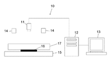
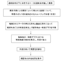
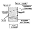
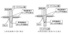
- FIG. 1 It is a schematic diagram of the visibility evaluation apparatus of the transparent base material which concerns on embodiment of this invention. It is a flowchart of the visibility evaluation method of the transparent base material which concerns on embodiment of this invention. It is a schematic diagram which defines Bt and Bb in case a mark width is about 1.3 mm. It is a schematic diagram which defines Bt and Bb in case a mark width is about 0.3 mm. It is a schematic diagram which defines k1 and k2. It is a schematic diagram of the positioning apparatus of the laminated body which concerns on embodiment of this invention. It is a flowchart of the positioning method of the laminated body which concerns on embodiment of this invention. FIG.
- FIG. 5 is a schematic diagram showing a configuration of a photographing unit and a method for measuring the inclination of a lightness curve when evaluating the inclination of the lightness curve when the mark width is 0.1 to 0.4 mm.
- FIG. 6 is a schematic diagram showing the configuration of the photographing means and the method of measuring the inclination of the brightness curve when evaluating the inclination of the brightness curve when the mark width is 1.0 to 2.0 mm. It is a schematic diagram of the evaluation apparatus of the surface state of the copper foil which concerns on embodiment of this invention. It is a flowchart of the evaluation method of the surface state of the copper foil which concerns on embodiment of this invention.
- FIG. 1 is a schematic diagram of a visibility evaluation apparatus 10 for a transparent substrate according to an embodiment of the present invention.
- the transparent substrate visibility evaluation apparatus 10 includes a photographing unit 11 that photographs the mark 16 existing under the transparent substrate 17 provided on the stage 15 through the transparent substrate 17.
- a computer 12 that performs various processes based on image signals from the imaging means 11, a display means 13 that displays predetermined images and the like based on various signals from the computer 12, a transparent substrate 17 on the stage, and a mark 16 is provided with illumination means 14 for irradiating light.
- the transparent substrate 17 to be evaluated in the present invention is not particularly limited, and may be a resin substrate such as glass or polyimide as long as it is transparent.
- the term “transparent” includes light transparency.
- the mark in the present invention may be a mark printed on a printed matter such as paper, or may be a copper wiring, and may take any form as long as it is a mark serving as a mark.
- the mark may be a printed material, a metal, an inorganic material, an organic material, or any mark. If the mark is a line, it is easy to create an observation point-lightness graph by measuring the lightness of each observation point along the direction crossing the observed mark in the image obtained by photographing. .
- the flexible printed wiring board is subjected to processing such as bonding to a liquid crystal substrate and mounting of an IC chip.
- the alignment at this time is the resin insulation layer that remains after etching the copper foil of the copper-clad laminate.
- the visibility of the resin insulating layer is important because it is performed through a positioning pattern that is visible through the screen.
- the transparent substrate is roughened with a surface-treated metal foil on which at least one surface has been subjected to a surface treatment such as a roughening treatment.
- the metal foil may be removed by etching after bonding to at least one surface of the transparent substrate from the surface side subjected to surface treatment such as treatment.
- the transparent base material is obtained by attaching the surface-treated metal foil to both surfaces of the transparent base material from the surface side subjected to surface treatment such as roughening treatment, and then performing etching to remove the metal foil on both sides. It may be produced.
- the said metal foil is not specifically limited, Copper foil, aluminum foil, nickel foil, copper alloy foil, nickel alloy foil, aluminum alloy foil, stainless steel foil, iron foil, iron alloy foil, etc. can be used.
- the imaging means 11 includes an imaging device, an image processing unit configured with an image processing circuit to which an output of the imaging device is input, a control unit configured with a control circuit that controls the image processing unit, a lens, and the like. Equipped with an optical system.
- a CCD camera or the like can be used as the photographing means 11.
- the photographing means 11 photographs the mark 16 existing under the transparent base material 17 provided on the stage 15 through the transparent base material 17 and acquires an image.
- the computer 12 performs various processes based on the image signal from the imaging means 11.
- the computer 12 measures the lightness at each observation point along the direction intersecting the direction in which the observed mark 16 extends with respect to the image signal from the image pickup means 11, and creates an observation point-lightness graph.
- a visibility evaluation means for evaluating the visibility of the transparent substrate 17 based on the slope of the brightness curve generated from the end of the mark 16 to the portion without the mark 16 in the observation point-lightness graph.
- the observation point-lightness graph creating means may create the observation point-lightness graph by measuring the lightness of each observation point along the direction perpendicular to the direction in which the observed mark 16 extends.
- the computer 12 further includes smoothing processing means for reducing variation in brightness of an image obtained by photographing by the photographing means 11, and the observation point-lightness graph creating means uses the lightness after the smoothing processing to observe point-lightness.
- a graph may be created.
- the mark 16 existing under the transparent base material 17 is a line-shaped mark 16 printed on a printed material laid under the transparent base material 17, and the observation point-lightness graph preparation means is obtained by photographing.
- the brightness at each observation point may be measured along a direction perpendicular to the direction in which the observed line-shaped mark 16 extends to create an observation point-lightness graph.
- the computer 12 includes a memory as a storage means.
- the digitized image from the imaging means 11, the observation point-lightness graph creation formula, the visibility evaluation formula, the evaluation value at each stage, and the like are recorded (so-called stored) so as to be readable by a computer.
- the display means 13 displays a predetermined image such as an observation point-lightness graph and a visibility evaluation result, a numerical value, and the like based on various signals from the computer 12.
- the flowchart shown in FIG. 2 is an embodiment of a visibility evaluation method using the transparent substrate visibility evaluation apparatus 10 according to the present invention, and an evaluation method that can be realized by the visibility evaluation apparatus 10 of the present invention is as follows.
- the present invention is not limited to that shown in the flowchart of FIG.
- the smoothing process is performed before creating the observation point-lightness graph for the image obtained by shooting in FIG. 2.
- the present invention is not limited to this, for example, after creating the observation point-lightness graph. You may go.
- the visibility evaluation method using the visibility evaluation apparatus 10 for a transparent substrate first, the mark 16 existing under the transparent substrate 17 is photographed by the photographing means 11 through the transparent substrate 17.
- the signal of the image photographed by the photographing means 11 is sent to the computer 12.
- the observation point-lightness graph creating means of the computer 12 measures the lightness of each observation point along the direction perpendicular to the direction in which the observed mark 16 extends with respect to the image signal from the image pickup means 11 and observes it. Is made.
- the visibility evaluation means of the computer 12 evaluates the visibility of the transparent substrate 17 based on the slope of the brightness curve generated from the end of the mark 16 to the portion where the mark 16 is not present in the observation point-lightness graph.
- the polyimide substrate When a polyimide substrate is used as the transparent base material 17 to be evaluated in the present invention, the polyimide substrate has a thickness of 50 ⁇ m, and the mark 16 extends from the end of the mark 16 on the polyimide substrate before being bonded to a metal foil.
- the polyimide substrate when using a polyimide substrate as the transparent base material 17 to be evaluated in the present invention, the polyimide substrate has a thickness of 50 ⁇ m and from the end of the mark 16 on the polyimide substrate before being bonded to the metal foil.
- the visibility evaluation unit of the computer 12 removes the metal foil by etching after bonding the surface-treated metal foil to at least one surface of the polyimide substrate from the surface-treated surface side subjected to surface treatment such as roughening treatment.
- the visibility evaluation unit of the computer 12 may further use the inclination k2 expressed by the angle of the lightness curve in the depth range from the intersection of the lightness curve and Bt to 0.1 ⁇ B with reference to Bt for further evaluation. . Furthermore, it may be determined that the case where k2 is 30 ° or more is even better. According to such an evaluation apparatus, it becomes possible to evaluate the visibility of the transparent substrate efficiently and more accurately.
- the computer 12 further includes smoothing processing means for reducing variation in brightness of an image obtained by photographing by the photographing means 11, and the observation point-lightness graph creating means uses the lightness after the smoothing processing to observe point-lightness. It is preferable to create a graph. Since smoothing processing by the smoothing processing means is performed on the data (original waveform) including lightness noise obtained from the image obtained by the photographing by the photographing means 11, the variation in the lightness is reduced. The visibility of the material 17 can be more accurately evaluated.
- the smoothing processing by the smoothing processing means can be performed by various smoothing programs. For example, smoothing processing by a second-third order polynomial fitting method, smoothing processing by Fourier transform, or smoothing processing by a moving average method is used. be able to.
- the smoothing process may be performed using various known smoothing programs. Further, the smoothing process of the brightness data may be performed for both the portion with the mark 16 and the portion without the mark 16, may be performed for the portion with the mark 16, may be performed on the portion without the mark 16, or may be performed partially. May be.
- observation point-lightness graph of data (original waveform) including noise of the lightness may be prepared in advance before performing the lightness smoothing process on the image obtained by the photographing by the photographing means 11.
- top average value Bt of the lightness curve “bottom average value Bb of the lightness curve”, “slope k1 represented by the angle of the lightness curve”, and “slope represented by the angle of the lightness curve described later” “k2” will be described with reference to the drawings.
- the width of the mark 16 is increased (for example, the width of the mark 16 is 0.7 mm or more, for example, 0.8 mm or more, for example, 5 mm or less, 4 mm or less, for example, about 1.
- the width of the mark 16 is reduced (for example, the width of the mark 16 is 0.01 mm or more, 0.05 mm or more, 0.1 mm or more, 0.8 mm or less, 0.7 mm).
- the width of the mark 16 is 0.01 mm or more, 0.05 mm or more, 0.1 mm or more, 0.8 mm or less, 0.7 mm.
- FIG. 3 is a schematic diagram for defining Bt and Bb when the width of the mark 16 is increased (about 1.3 mm).
- a “mark” in FIG. 3 indicates a line-shaped mark 16 (width of about 1.3 mm) of the printed matter observed in an image obtained by photographing with the CCD camera.
- a curve drawn so as to overlap the mark 16 shows a brightness curve generated from the end of the mark 16 to a portion where the mark 16 is not present in the observation point-lightness graph.
- the “top average value Bt of the lightness curve” is the lightness when measured at 5 points (at a total of 10 points on both sides) at 30 ⁇ m intervals from a position 100 ⁇ m away from the end positions on both sides of the mark 16. Average values are shown.
- the “bottom average value Bb of the lightness curve” indicates an average value of lightness when 11 positions are measured at 100 ⁇ m intervals from a position entering 100 ⁇ m inside from the end position of the mark 16.
- the interval between observation points for measuring the average value of brightness can be appropriately selected within the range of 1 ⁇ m to 500 ⁇ m depending on the shape of the brightness curve.
- it is preferable that the intervals between the observation points are substantially equal or equal. Note that the intervals between the observation points do not have to be substantially equal and may not be equal. Further, it is considered that the wider the measurement interval, the more the influence of a specific observation point can be eliminated and the error due to the observation point can be reduced.
- FIG. 4A and 4B are schematic diagrams for defining Bt and Bb when the width of the mark 16 is about 0.3 mm.
- the “top average value Bt of the lightness curve” is 5 at intervals of 30 ⁇ m as in the case where the width of the mark 16 is about 1.3 mm from a position 50 ⁇ m away from the end positions on both sides of the mark 16.
- the average value of the brightness when measured at a place is shown.
- the “bottom average value Bb of the lightness curve” indicates the minimum value of lightness at the tip of the V-shaped valley when the lightness curve is V-shaped as shown in FIG. When it has the bottom of (b), the value of the center part of about 0.3 mm is shown.
- the interval between observation points for measuring the average value of brightness can be appropriately selected within the range of 1 ⁇ m to 500 ⁇ m depending on the shape of the brightness curve. In order to avoid the bias of the observation points, it is preferable that the intervals between the observation points are substantially equal or equal. Note that the intervals between the observation points may not be substantially equal, and may not be equal. Further, it is considered that the wider the measurement interval, the more the influence of a specific observation point can be eliminated and the error due to the observation point can be reduced.
- FIG. 5 shows a schematic diagram defining k1 and k2.
- One pixel on the horizontal axis corresponds to a length of 10 ⁇ m.
- the value of k1 (°) was calculated in the lightness curve graph of 5: 5). Further, k1 is measured on both sides of the mark 16, and a value having a small inclination expressed by an angle is adopted.
- One pixel on the horizontal axis corresponds to a length of 10 ⁇ m.
- the value of k1 (°) was calculated in the lightness curve graph of 5: 5).
- k2 is measured on both sides of the mark 16, and a value having a small inclination expressed by an angle is adopted. Further, when the shape of the lightness curve is unstable and there are a plurality of the “intersections between the lightness curve and Bt”, the intersection closest to the mark 16 is adopted.
- ⁇ B (PI) indicates the difference between the top average value Bt and the bottom average value Bb of the lightness curve for the polyimide before being bonded to a metal foil such as a copper foil.
- the brightness is high in the portion where the mark 16 is not attached, but the brightness decreases as soon as the end of the mark 16 is reached. If the visibility of the polyimide substrate is good, such a lowered state of brightness is clearly observed. On the other hand, if the visibility of the polyimide substrate is poor, the brightness is not suddenly lowered from “high” to “low” at the end of the mark 16 at a stretch, but the state of decline is moderate and the state of decline in brightness is not good. It becomes clear.
- the present invention is based on such knowledge, the polyimide substrate from which the metal foil such as the surface-treated copper foil is bonded and removed, the printed matter with the mark 16 placed on the bottom, and photographed with a CCD camera over the polyimide substrate.
- k1 is preferably 65 ° or more, and more preferably 87 ° or less.
- the upper limit of k1 is preferably 87 ° or less, more preferably 85 ° or less, and even more preferably 83 ° or less.
- k1 exceeds 87 °, the peel strength may be reduced.
- the upper limit of ⁇ B / ⁇ B (PI) need not be specified, but is, for example, 1.70 or less, or 1.50 or less, or 1.40 or less.
- the depth from the intersection of the lightness curve and Bt to 0.1 ⁇ B on the basis of Bt.
- k2 is more preferably 35 ° or more, and more preferably 40 ° or more.
- the upper limit of k2 is not particularly limited, but is, for example, 87 ° or less, alternatively 82 ° or less, alternatively 77 ° or less, or 72 ° or less.
- the roughening treatment means, for example, physical polishing or treatment (mechanical polishing, buffing, sandblasting, etc.) or chemical polishing or treatment (pickling, roughening plating ( It refers to a treatment for increasing the irregularities on the surface of the metal foil by performing plating or the like for electrodeposition of roughened particles)).
- the surface treatment means a physical or chemical treatment on the surface of the metal foil such as roughening treatment, wet plating treatment, dry plating treatment (including sputtering treatment and vapor deposition treatment), chemical polishing treatment, mechanical polishing treatment, etc. A process that performs processing.
- the visibility of the transparent substrate can be efficiently and accurately evaluated by causing the computer to execute the processing procedure as described above as a program.
- this program recorded on a recording medium such as an optical or magnetic disk so that it can be read by a computer, this program can be realized on other computers, and the same effects as the above-described processing procedure can be obtained. .
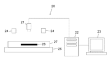
- FIG. 6 is a schematic diagram of a positioning device 20 for a laminate according to an embodiment of the present invention.
- the laminated body positioning device 20 includes an imaging unit 21 that images a mark 26 existing in a laminated body 27 of metal and resin provided on a stage 25 through a resin, and an imaging unit.
- Computer 22 that performs various processes based on image signals from 21, display means 23 that displays predetermined images and the like based on various signals from computer 22, and illumination that irradiates light on laminated body 27 on the stage Means 24.
- the form of the laminate 27 of metal and resin is not particularly limited as long as it is configured by bonding a metal to a resin.
- a specific example of the laminate 27 of metal and resin in the present invention copper or the like is used on at least one surface of a resin such as polyimide, which is used to electrically connect the main body substrate and the attached circuit board.
- a laminate is produced by accurately positioning the flexible printed circuit board and crimping the flexible printed circuit board to the wiring ends of the main circuit board and the attached circuit board. Can be mentioned.
- the laminate 27 is a laminate in which the wiring end portions of the flexible printed circuit board and the main body substrate are bonded together by pressure bonding, or the wiring edge portions of the flexible printed circuit board and the circuit board are bonded together by pressure bonding.
- the resulting laminate is obtained.
- the laminate 27 has a part of the metal wiring and a mark formed of a separate material. The position of the mark is not particularly limited as long as it can be photographed by the photographing means 21 such as a CCD camera through the resin constituting the laminated body 27.
- the photographing means 21 includes an imaging device, an image processing unit configured with an image processing circuit to which an output of the imaging device is input, a control unit configured with a control circuit that controls the image processing unit, a lens, and the like. Equipped with an optical system.
- a CCD camera or the like can be used as the photographing means 21.
- the photographing means 21 obtains an image by photographing the mark 26 present in the laminated body 27 provided on the stage 25 through the resin of the laminated body.
- the computer 22 performs various processes based on the image signal from the imaging means 21.
- the computer 22 measures the lightness of each observation point along the direction intersecting the direction in which the observed mark 26 extends with respect to the image signal from the imaging means 21, and creates an observation point-lightness graph.
- positioning means for determining the position of the laminated body 27 by the inclination of the brightness curve generated from the end of the mark 26 to the portion where the mark 26 is not present in the observation point-lightness graph.
- the observation point-lightness graph creating means may measure the lightness of each observation point along the direction perpendicular to the direction in which the observed mark 26 extends to create the observation point-lightness graph.
- the computer 22 further includes smoothing processing means for reducing variations in lightness of the image obtained by photographing by the photographing means 21, and the observation point-lightness graph creating means uses the lightness after the smoothing processing to observe point-lightness.
- a graph may be created.
- the computer 22 includes a memory as a storage means.
- the digitized image from the imaging means 21, the observation point-lightness graph creation formula, the positioning formula, the evaluation value at each stage, and the like are recorded (so-called stored) so as to be readable by a computer.
- the display means 23 displays a predetermined image such as an observation point-lightness graph, a position evaluation result, a numerical value, and the like based on various signals from the computer 22.
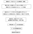
- FIG. 7 is an embodiment of a positioning method using the laminate positioning device 20 according to the present invention, and an evaluation method that can be realized by the positioning device 20 of the present invention is shown in the flowchart of FIG. It is not limited to things.
- the smoothing process is performed before creating the observation point-lightness graph for the image obtained by shooting in FIG. 7, but the present invention is not limited to this. For example, after the observation point-lightness graph is created, smoothing processing is performed. You may go.
- the image 26 is photographed by the photographing means 21 over the mark 26 existing in the laminated body 27 of metal and resin provided on the stage 25.
- the signal of the image photographed by the photographing means 21 is sent to the computer 22.
- the observation point-lightness graph preparation means of the computer 22 measures the lightness of each observation point along the direction perpendicular to the direction in which the observed mark 26 extends with respect to the image signal from the image pickup means 21, thereby observing point-lightness graph. Is made.
- the positioning means of the computer 22 evaluates the position of the laminated body 27 based on the slope of the brightness curve generated from the end of the mark 26 to the portion where the mark 26 is not present in the observation point-lightness graph.
- the positioning means of the computer 22 is produced by attaching the surface-treated metal foil to at least one surface of the polyimide substrate from the surface side subjected to surface treatment such as roughening treatment, and then removing the metal foil by etching.
- the visibility evaluation means of the computer 22 may further use the inclination k2 expressed by the angle of the lightness curve in the depth range from the intersection of the lightness curve and Bt to 0.1 ⁇ B with reference to Bt for evaluation. .
- the position of the mark 26 can be detected, and the laminate 27 of metal and resin can be positioned based on the detected position of the mark 26.
- the definition of Bt, Bb, k1, and k2 is as described in the visibility evaluation of the transparent base material, and according to such a positioning method, the boundary between the mark 26 and the part that is not the mark 26 is clearer. Therefore, positioning accuracy is improved, errors due to mark image recognition are reduced, and more accurate alignment can be performed.
- the position detecting device can determine that the mark 26 exists at the position.
- ⁇ B (PI) is 20 or more and 33 or less
- the ratio of ⁇ B / ⁇ B (PI) is 0.7 or more
- k1 is 65 ° or more
- further 87 ° or less or k2 is 30 °.
- the determination that the mark 26 exists at the position can be made by a device that detects the position.
- the computer 22 further includes smoothing processing means for reducing variations in lightness of the image obtained by photographing by the photographing means 21, and the observation point-lightness graph creating means uses the lightness after the smoothing processing to observe point-lightness. It is preferable to create a graph.
- the smoothing processing by the smoothing processing means can be performed by various smoothing programs. For example, smoothing processing by a second-third order polynomial fitting method, smoothing processing by Fourier transform, or smoothing processing by a moving average method is used. be able to.
- an observation point-lightness graph of data (original waveform) including the lightness noise may be prepared in advance before performing the lightness smoothing process.
- the laminated body positioning device 20 may further include an alignment means (not shown) for aligning the laminated body (including a copper-resin laminated body and a printed wiring board) whose position has been determined.
- the positioning means include a moving device and a moving means that can move the stacked body.
- a moving device or moving means for example, a conveyor such as a belt conveyor or a chain conveyor, a moving device or moving means equipped with an arm mechanism, a moving device or moving means that moves by suspending a laminate using gas, a substantially cylindrical shape Moving devices and moving means (including rollers and bearings) that move the laminate by rotating objects such as, moving devices and moving means that use hydraulic pressure as a power source, moving devices and moving means that use air pressure as a power source, Using a moving device or moving means having a stage such as a moving device or moving means using a motor as a power source, a gantry moving linear guide stage, a gantry moving air guide stage, a stack type linear guide stage, or a linear motor drive stage Also good. Moreover, you may use a well-known moving apparatus and a moving means as a moving apparatus or a moving means.
- the positioning device 20 according to the embodiment of the present invention may have a surface mounting machine, or the positioning device according to the embodiment of the present invention may be installed in the surface mounting machine.
- the printed wiring having a resin plate and a circuit provided on the resin plate, the laminate of the metal and the resin positioned by the positioning device. It may be a plate. In that case, the mark may be the circuit.
- the positioning of the laminate can be efficiently and accurately evaluated by causing the computer to execute the processing procedure as described above as a program.
- this program recorded on a recording medium such as an optical or magnetic disk so that it can be read by a computer, this program can be realized on other computers, and the same effects as the above-described processing procedure can be obtained. .
- positioning includes “detecting the position of a mark or an object”.
- alignment includes “after detecting the position of a mark or object, moving the mark or object to a predetermined position based on the detected position”.
- the printed wiring board may be manufactured by positioning the printed wiring board with the printed wiring board positioning device of the present invention and mounting the components on the positioned printed wiring board. Further, the printed wiring board positioning device of the present invention positions the printed wiring board, aligns the positioned printed wiring board, and mounts the components on the aligned printed wiring board. May be manufactured. Thereby, components, such as an electronic component, can be mounted
- the printed wiring board may be manufactured by positioning the printed wiring board with the printed wiring board positioning device of the present invention and connecting another printed wiring board to the positioned printed wiring board. Further, the printed wiring board positioning device of the present invention positions the printed wiring board, aligns the positioned printed wiring board, and connects another printed wiring board to the aligned printed wiring board. A printed wiring board may be manufactured. Thereby, another printed wiring board can be connected to an accurate position on the printed wiring board to be connected.
- the “connection” may be an electrical connection (for example, soldering), or may be a connection using an adhesive or the like, which is not an electrical connection.
- the “printed wiring board” includes a printed wiring board and a printed board on which components are mounted.
- FIG. 10 is a schematic diagram of an evaluation apparatus 10 ′ for the surface state of a copper foil according to an embodiment of the present invention.
- the copper foil surface state evaluation apparatus 10 ′ according to the embodiment of the present invention photographs the mark 16 ′ existing under the transparent base material 17 ′ provided on the stage 15 ′ through the transparent base material 17 ′.
- the metal foil is removed by etching.
- the said metal foil is not specifically limited, Copper foil, aluminum foil, nickel foil, copper alloy foil, nickel alloy foil, aluminum alloy foil, stainless steel foil, iron foil, iron alloy foil, etc. can be used.
- the photographing means 11 ′ is composed of an imaging device, an image processing circuit configured with an image processing circuit to which an output of the imaging device is input, a control unit configured with a control circuit that controls the image processing unit, etc., a lens, and the like. Provided with an optical system.
- a CCD camera or the like can be used as the photographing unit 11 '.
- the photographing unit 11 ′ photographs the mark 16 ′ existing under the transparent base material 17 ′ provided on the stage 15 ′ through the transparent base material 17 ′ to obtain an image.
- the computer 12 performs various processes based on the image signal from the imaging means 11'.
- the computer 12 ′ measures the lightness of each observation point along the direction intersecting the direction in which the observed mark 16 ′ extends with respect to the image signal from the imaging means 11 ′, and creates an observation point—lightness graph—
- the visibility of the transparent base material 17 ′ is evaluated by the inclination of the lightness curve generated from the end of the mark 16 ′ to the portion where the mark 16 ′ is not present, and the visibility is evaluated.
- a copper foil surface state evaluating means for evaluating the surface state of the copper foil based on the result.
- the observation point-lightness graph creating means may measure the lightness of each observation point along the direction perpendicular to the direction in which the observed mark 16 ′ extends to create the observation point-lightness graph.
- the computer 12 ′ further includes smoothing processing means for reducing variations in brightness of an image obtained by photographing by the photographing means 11 ′, and the observation point-lightness graph creating means uses the lightness after the smoothing processing to observe the observation point.
- -A brightness graph may be produced.
- the mark 16 ′ existing under the transparent substrate 17 ′ is a line-shaped mark 16 ′ printed on a printed material laid under the transparent substrate 17 ′.
- the brightness at each observation point may be measured along a direction perpendicular to the direction in which the observed line-shaped mark 16 ′ extends, to create an observation point-lightness graph.
- the computer 12 includes a memory as storage means.
- the digitized image from the imaging means 11 ′, observation point-brightness graph preparation formula, visibility evaluation formula, copper foil surface condition evaluation formula, evaluation value at each stage, etc. can be read by a computer. It is recorded (so-called storage).
- the display means 13 ' displays a predetermined image such as an observation point-brightness graph, a visibility evaluation result, and a copper foil surface state evaluation result, numerical values, and the like based on various signals from the computer 12'.
- a surface-treated metal foil having at least one surface subjected to a surface treatment such as a roughening treatment is subjected to a roughening treatment or the like.
- a transparent base material 17 ′ prepared by removing the metal foil by etching after being attached to at least one surface of the transparent base material from the surface side subjected to the surface treatment is prepared.
- the mark 16 'existing under the transparent base material 17 is photographed by the photographing means 11' through the transparent base material 17 '.
- the signal of the image photographed by the photographing means 11 ' is sent to the computer 12'.
- the observation point-lightness graph creating means of the computer 12 ′ measures the lightness of each observation point along the direction perpendicular to the direction in which the observed mark 16 ′ extends with respect to the image signal from the image pickup means 11 ′. -Create a brightness graph.
- the surface condition evaluation means for the copper foil of the computer 12 ′ evaluates the visibility of the transparent base material 17 ′ by the inclination of the brightness curve generated from the end of the mark 16 ′ to the portion without the mark 16 in the observation point-lightness graph. Then, based on the visibility evaluation result, the surface state of the surface-treated metal foil bonded to the transparent substrate 17 ′ is evaluated. Conventionally, unless actually produced on the production line, it was impossible to determine whether or not the marks provided for alignment etc.
- the polyimide substrate When a polyimide substrate is used as the transparent substrate 17 ′ to be evaluated in the present invention, the polyimide substrate has a thickness of 50 ⁇ m, and from the end of the mark 16 ′ on the polyimide substrate before being bonded to the metal foil.
- the polyimide substrate When a polyimide substrate is used as the transparent base material 17 ′ to be evaluated in the present invention, the polyimide substrate has a thickness of 50 ⁇ m and the end of the mark 16 ′ on the polyimide substrate before being bonded to the metal foil.
- the surface condition evaluation means for the copper foil of the computer 12 ′ is obtained by bonding the surface-treated metal foil to at least one surface of the polyimide substrate from the surface-treated surface side subjected to surface treatment such as roughening treatment, and then etching.
- the difference ⁇ B ( ⁇ B Bt ⁇ Bb) between the top average value Bt and the bottom average value Bb of the brightness curve generated from the end of the mark 16 ′ to the portion without the mark 16 ′ for the polyimide substrate manufactured by removing the metal foil ), A ratio of ⁇ B / ⁇ B (PI), and a slope k1 represented by an angle of the brightness curve in a predetermined depth range with reference to Bt.
- -Bb) is 20 or more and 33 or less
- the ratio of ⁇ B / ⁇ B (PI) is 0.7 or more, and is represented by the angle of the brightness curve in the depth range of 0.4 ⁇ B to 0.6 ⁇ B with respect to Bt.
- the case where the tilt k1 is 65 ° or more is determined to be good, the case where it is 87 ° or less is determined to be better, and the surface condition of the copper foil is good when the visibility evaluation is good You may determine that there is.
- k1 is preferably 65 ° or more, more preferably 87 ° or less.
- the upper limit of k1 is preferably 87 ° or less, more preferably 85 ° or less, and even more preferably 83 ° or less. When k1 exceeds 87 °, the peel strength may be reduced.
- the upper limit of ⁇ B / ⁇ B (PI) need not be specified, but is, for example, 1.70 or less, or 1.50 or less, or 1.40 or less.
- observation point-lightness graph prepared by the observation point-lightness graph preparation means of the computer 12 ' from the image obtained by the photographing means 11', from the intersection of the lightness curve and Bt to 0.1 ⁇ B on the basis of Bt. If the slope k2 expressed by the angle of the lightness curve in the depth range is 30 ° or more, it may be further evaluated that the visibility is good, and thereby the surface state of the copper foil may be evaluated as good. . According to such a configuration, the boundary between the mark 16 ′ and the portion that is not the mark 16 ′ becomes clearer, the positioning accuracy is improved, the error due to the mark image recognition is reduced, and the alignment can be performed more accurately. It becomes like this.
- the evaluation of the surface state of the copper foil has been described.
- the present invention is not limited to this, and the same evaluation can be made even if the surface state of the metal foil is used.
- the said metal foil is not specifically limited, Copper foil, aluminum foil, nickel foil, copper alloy foil, nickel alloy foil, aluminum alloy foil, stainless steel foil, iron foil, iron alloy foil, etc. can be used.
- the visibility of the transparent substrate can be efficiently and accurately evaluated by causing the computer to execute the processing procedure as described above as a program.
- this program recorded on a recording medium such as an optical or magnetic disk so that it can be read by a computer, this program can be realized on other computers, and the same effects as the above-described processing procedure can be obtained. .
- the transparent substrate visibility evaluation method of the present invention is to prepare a mark and a transparent substrate provided on the mark, photograph the mark with a CCD camera over the transparent substrate, and observe an image obtained by photographing.
- the brightness at each observation point is measured along the direction crossing the marked mark, and an observation point-lightness graph is created.
- the slope of the lightness curve that occurs from the end of the mark to the part without the mark This is a method for evaluating the visibility of a transparent substrate.
- the present invention with such a configuration, it is possible to easily and efficiently evaluate the visibility of the transparent substrate easily and efficiently even in the laboratory alone.
- the slope of the lightness curve generated from the end of the mark to the portion without the mark is expressed as an angle, and the visibility of the transparent substrate is evaluated by the angle, the visibility of the transparent substrate is more efficiently observed. It is possible to accurately evaluate the property, which is preferable.
- the shape of the mark is not particularly limited, but if it is a line-shaped mark, the brightness of each observation point is measured along the direction crossing the observed mark, and an observation point-lightness graph is obtained. It is easy to create and is preferable.
- the flexible printed wiring board is subjected to processing such as bonding to a liquid crystal substrate and mounting of an IC chip.
- the alignment at this time is the resin insulation layer that remains after etching the copper foil of the copper-clad laminate.
- the visibility of the resin insulating layer is important because it is performed through a positioning pattern that is visible through the screen.
- the transparent base material is a surface-treated metal foil having at least one surface roughened before being provided on the mark. After bonding to at least one surface of the transparent base material from the surface of the roughening treatment, the metal foil may be removed by etching.
- the transparent base material may be produced by attaching the surface-treated metal foil to both surfaces of the transparent base material from the roughened surface side and then performing etching to remove the metal foil on both surfaces.
- the metal foil used in the present invention is not particularly limited, and copper foil, aluminum foil, nickel foil, copper alloy foil, nickel alloy foil, aluminum alloy foil, stainless steel foil, iron foil, iron alloy foil and the like can be used.
- the transparent substrate to be evaluated in the present invention is not particularly limited, and may be a glass or resin substrate as long as it is transparent.
- the term “transparent” includes light transparency.
- a polyimide substrate will be described as an example of the transparent base material.
- the copper foil of both surfaces is removed by an etching.
- the mark is photographed with a CCD camera through the polyimide substrate, and the observed line-shaped mark extends in the image obtained by the photographing.
- the brightness at each observation point is measured along the direction perpendicular to the observation point, and the observation point-lightness graph is created.
- the observation point-lightness graph the lightness curve generated from the end of the mark to the part without the mark is represented by the angle.
- the visibility of the polyimide can be evaluated by the tilt.
- an inclination k2 expressed by an angle of the lightness curve in a depth range from the intersection of the lightness curve and Bt to 0.1 ⁇ B with respect to Bt is used. Furthermore, you may use for evaluation. Furthermore, you may determine with the case where k2 becomes 30 degrees or more still better. According to such an evaluation method, it becomes possible to efficiently and more accurately evaluate the visibility of the transparent substrate.
- top average value Bt of the lightness curve “bottom average value Bb of the lightness curve”, “slope k1 represented by the angle of the lightness curve”, “slope k2 represented by the angle of the lightness curve”, “ The definitions of “ ⁇ B” and “ ⁇ B (PI)” are the same as those shown in the above-described transparent substrate visibility evaluation apparatus and visibility evaluation method.
- the smoothing process can be performed by various smoothing programs. For example, a smoothing process using a second-third-order polynomial fitting method, a smoothing process using Fourier transform, a smoothing process using a moving average method, or the like can be used. Note that an observation point-lightness graph of data (original waveform) including noise of the lightness may be generated in advance before performing the lightness smoothing process on the image obtained by photographing.
- a laminate of metal and resin is prepared.
- the form of the laminate of the metal and the resin is not particularly limited as long as it is configured by bonding the metal to the resin.
- copper or the like is used on at least one surface of a resin such as polyimide, which is used to electrically connect the main body substrate and the attached circuit board, and the circuit board.
- a resin such as polyimide
- the laminate is a laminate in which the wiring end portions of the flexible printed circuit board and the main body substrate are bonded together by pressure bonding, or the wiring edge portions of the flexible printed circuit board and the circuit board are bonded together by pressure bonding. It becomes a laminated body.
- the laminate has a mark formed of a part of the metal wiring and a separate material. The position of the mark is not particularly limited as long as it can be photographed with a CCD camera through the resin constituting the laminate.
- the above-mentioned mark is photographed with a CCD camera through the resin of the layered body, and for the image obtained by photographing, the brightness at each observation point along the direction crossing the observed mark Is measured to create an observation point-lightness graph, and the metal / resin laminate is positioned based on the slope of the lightness curve generated from the end of the mark to the portion without the mark. Further, when the inclination of the lightness curve is represented by an angle and the laminate of the metal and the resin is positioned by the angle, the laminate can be positioned more accurately.
- the angle representing the slope of the lightness curve used here is the difference ⁇ B (PI), ⁇ B / ⁇ B between the top average value Bt and the bottom average value Bb of the lightness curve, as in the above-described visibility evaluation method of the transparent substrate.
- the slope k2 expressed by the angle of the brightness curve at can be used.
- the boundary between the mark and the non-mark portion becomes clearer, the positioning accuracy is improved, the error due to the mark image recognition is reduced, and the alignment can be performed more accurately.
- the device that detects the position can determine that the mark exists at the position.
- the resin constituting the laminate is a polyimide substrate with a thickness of 50 ⁇ m
- the device can do it.
- the apparatus and method include an apparatus and a method for determining whether or not the mark included in the stacked body exists. I can say that.
- the positioning method according to the embodiment of the present invention may use a surface mounter or a chip mounter. Further, in the positioning method according to the embodiment of the present invention, the laminate of the metal and the transparent substrate includes a transparent substrate plate and a circuit provided on the transparent substrate plate. It may be. In that case, the mark may be the circuit.
- the printed wiring board may be manufactured by positioning the printed wiring board by the positioning method of the present invention, and mounting the components on the positioned printed wiring board. Further, the printed wiring board is positioned by the printed wiring board positioning method of the present invention, the positioned printed wiring board is aligned, and a component is mounted on the aligned printed wiring board. May be manufactured. Thereby, components, such as an electronic component, can be mounted
- the printed wiring board may be manufactured by positioning the printed wiring board by the positioning method of the present invention and connecting another printed wiring board to the positioned printed wiring board. Further, the printed wiring board is positioned by the printed wiring board positioning method of the present invention, the positioned printed wiring board is aligned, and another printed wiring board is connected to the aligned printed wiring board. A printed wiring board may be manufactured. Thereby, another printed wiring board can be connected to an accurate position on the printed wiring board to be connected.
- the “connection” may be an electrical connection (for example, soldering), or may be a connection using an adhesive or the like, which is not an electrical connection.
- the “printed wiring board” includes a printed wiring board and a printed board on which components are mounted.
- Example A1 to Example A13, Example A15 to Example A20, Example A22 to Example A23, Example B2, Example B4, Example B7 to Example B10, Example a1 to Example a13, Example a15 to Example a20, Example a22 to Example a23, Example b2, Example b4, and Example b7 to Example b10 were subjected to the following plating treatment for forming a heat resistant layer and a rust preventive layer.
- the conditions for forming the heat-resistant layer 1 are shown below.
- Liquid composition Nickel 5-20 g / L, Cobalt 1-8 g / L pH: 2-3 Liquid temperature: 40-60 ° C Current density: 5 to 20 A / dm 2 Coulomb amount: 10-20 As / dm 2
- a heat-resistant layer 2 was formed on the copper foil provided with the heat-resistant layer 1.
- the rolled copper foil was manufactured as follows. A copper ingot having the composition shown in Table 2 or 6 was manufactured, and after hot rolling, annealing and cold rolling of a continuous annealing line at 300 to 800 ° C. were repeated to obtain a rolled sheet having a thickness of 1 to 2 mm. This rolled sheet was annealed in a continuous annealing line at 300 to 800 ° C. and recrystallized, and finally cold-rolled to the thickness shown in Table 2 or 6 to obtain a copper foil. “Tough pitch copper” in the “type” column of Table 2 or 6 indicates tough pitch copper standardized in JIS H3100 C1100, and “oxygen-free copper” indicates oxygen-free copper standardized in JIS H3100 C1020. “Tough pitch copper + Ag: 100 ppm” means that 100 mass ppm of Ag is added to tough pitch copper.
- the electrolytic copper foil used was an electrolytic copper foil HLP foil manufactured by JX Nippon Mining & Metals.
- electrolytic polishing or chemical polishing was performed, the plate thickness after electrolytic polishing or chemical polishing was described.
- high gloss rolling means that the final cold rolling (cold rolling after the final recrystallization annealing) was performed at the value of the oil film equivalent.
- Normal rolling means that the final cold rolling (cold rolling after the final recrystallization annealing) was performed at the oil film equivalent value described.
- “Chemical polishing” and “electropolishing” mean the following conditions.
- “Chemical polishing” was performed using an etching solution of 1 to 3% by mass of H 2 SO 4 , 0.05 to 0.15% by mass of H 2 O 2 , and the remaining water, and the polishing time was 1 hour.
- “Electropolishing” is a condition of phosphoric acid 67% + sulfuric acid 10% + water 23%, voltage 10 V / cm 2 , and the time shown in Table 2 or 6 (when 10 seconds of electropolishing is performed, the polishing amount is 1 to 2 ⁇ m).
- Example A1 to Example A23 and Example B1 to Example B13 Upilex thickness 50 ⁇ m, examples a1 to a23 and examples b1 to examples made by Ube Industries
- b13 Kaneka thickness 50 ⁇ m
- etching ferric chloride aqueous solution
- FIG. 8 is a schematic diagram showing the configuration of the photographing apparatus used at this time and the method of measuring the slope of the brightness curve. ⁇ B and slopes k1 and k2 were measured as shown in FIG. One pixel on the horizontal axis corresponds to a length of 10 ⁇ m.
- the photographing means includes a CCD camera, a stage (white) on which a polyimide substrate is placed with a marked paper underneath, an illumination power source for irradiating light onto the photographing portion of the polyimide substrate, and a paper with a mark to be photographed.
- a transporter (not shown) for transporting the evaluation polyimide substrate placed below onto the stage is provided.
- the main specifications of the photographing means are as follows: ⁇ Photographing means: Nireco Corporation sheet inspection device Mujken CCD camera: 8192 pixels (160 MHz), 1024 gradation digital (10 bits) ⁇ Power supply for lighting: High-frequency lighting power supply (power supply unit x 2) ⁇ Lighting: Fluorescent lamp (30W)
- 0 means “black”
- lightness 255 means “white”
- the gray level from “black” to “white” (black and white shading, gray scale) Is divided into 256 gradations for display. Since the mark used has a small width of 0.1 to 0.4 mm, the brightness curve produced has a V shape as shown in FIG. 4 (a) or a bottom as shown in FIG. 4 (b). It became V type which has.
- Example A1 to Example A23 and Example B1 to Example B13 Ube Industries Upilex thickness 50 ⁇ m, Example a1 to Example a23 and Example b1 to Example b13: Kaneka thickness 50 ⁇ m
- the copper foil was removed by etching (ferric chloride aqueous solution) to prepare a sample film.
- a printed material black circle with a diameter of 6 cm was attached to one surface of the obtained resin layer, and the visibility of the printed material was judged from the opposite surface through the resin layer.
- ⁇ indicates that the outline of the black circle of the printed material is clear when the length is 90% or more of the circumference
- “Clear” indicates that the outline of the black circle is clear when the length is 80% or more and less than 90% of the circumference.
- “O” passesed above, a black circle with a clear outline of 0 to less than 80% of the circumference and a broken outline were evaluated as “x” (failed). And the evaluation of the said visibility was made into evaluation of the copper foil surface state as it is.
- Example A1 to Example A23 and Example B1 to Example B13 Ube Industries Upilex thickness 50 ⁇ m
- Example a1 to Example a23 and Example b1 to Example b13 Kaneka
- the copper foil was etched (ferric chloride aqueous solution) to form a FPC having a circuit width of L / S of 30 ⁇ m / 30 ⁇ m. After that, an attempt was made to detect a 20 ⁇ m ⁇ 20 ⁇ m square mark with a CCD camera through polyimide.
- FIG. 9 is a schematic diagram showing the configuration of the photographing means and the method of measuring the slope of the brightness curve when evaluating the slope of the brightness curve when the mark width is 1.0 to 2.0 mm.
- FIG. 7 is a schematic diagram showing the configuration of the photographing means and the method of measuring the slope of the brightness curve when evaluating the slope of the brightness curve when the mark width is 1.0 to 2.0 mm.
- the same results as in the above example were obtained, and as in the above example, the visibility of the polyimide substrate was evaluated easily and accurately at the laboratory level without actually producing it on the production line.
- the surface condition of the copper foil could be evaluated.
Landscapes
- General Health & Medical Sciences (AREA)
- Health & Medical Sciences (AREA)
- Life Sciences & Earth Sciences (AREA)
- Chemical & Material Sciences (AREA)
- Analytical Chemistry (AREA)
- Biochemistry (AREA)
- Physics & Mathematics (AREA)
- General Physics & Mathematics (AREA)
- Immunology (AREA)
- Pathology (AREA)
- Investigating Or Analysing Materials By Optical Means (AREA)
- Investigating Materials By The Use Of Optical Means Adapted For Particular Applications (AREA)
- Length Measuring Devices By Optical Means (AREA)
Abstract
透明基材の視認性を効率良く正確に評価する。透明基材の視認性評価装置は、透明基材の下に存在するマークを、透明基材越しに撮影する撮影手段と、撮影によって得られた画像について、観察された前記マークが伸びる方向と交わる方向に沿って観察地点ごとの明度を測定して観察地点-明度グラフを作製する観察地点-明度グラフ作製手段と、観察地点-明度グラフにおいて、マークの端部からマークがない部分にかけて生じる明度曲線の傾きに基づいて前記透明基材の視認性を評価する視認性評価手段とを備える。
Description
本発明は、透明基材の視認性評価装置、積層体の位置決め装置、判定装置、位置検出装置、金属箔の表面状態の評価装置、プログラム、記録媒体、プリント配線板の製造方法、透明基材の視認性評価方法、積層体の位置決め方法、判定方法、位置検出方法に関する。
スマートフォンやタブレットPCといった小型電子機器には、配線の容易性や軽量性からフレキシブルプリント配線板(以下、FPC)が採用されている。近年、これら電子機器の高機能化により信号伝送速度の高速化が進み、FPCにおいてもインピーダンス整合が重要な要素となっている。信号容量の増加に対するインピーダンス整合の方策として、FPCのベースとなる樹脂絶縁層(例えば、ポリイミド)の厚層化が進んでいる。一方、FPCは液晶基材への接合やICチップの搭載などの加工が施されるが、この際の位置合わせは銅箔と樹脂絶縁層との積層板における銅箔をエッチングした後に残る樹脂絶縁層を透過して視認される位置決めパターンを介して行われるため、樹脂絶縁層の視認性が重要となる。
このような樹脂絶縁層の視認性の評価方法として、特許文献1では、CCDカメラによって樹脂絶縁層越しに撮影した画像を観察して評価している。また、特許文献2では、評価対象の樹脂絶縁層の水平面に対して30°をなす角度からCCDカメラで撮影した画像にテストパターンが歪んで映っているか否かを評価している。
しかしながら、特許文献1のようにCCDカメラで観察して画像を単純に観察するものでは、視認性評価の精度には限界があり、製造ラインで実際に作製しなければ、位置合わせ等のために設けられたマークを透明基材越しに視認することが可能か否かを判断できないのが実情であり、製造コストの点で問題があった。これは特許文献2のように当該画像にテストパターンが歪んで映っているか否かを評価する方法であっても同様である。
本発明は、透明基材の視認性を効率良く正確に評価することができる透明基材の視認性評価装置、透明基材の視認性評価プログラム及びそれが記録されたコンピュータ読み取り可能な記録媒体を提供する。また、本発明は、積層体の位置決めを効率良く正確に行うことができる積層体の位置決め装置、積層体の位置決めプログラム及びそれが記録されたコンピュータ読み取り可能な記録媒体、及び、プリント配線板の製造方法を提供する。また、本発明は、銅箔の表面状態を効率良く正確に評価することができる銅箔の表面状態の評価装置、銅箔の表面状態の評価プログラム及びそれが記録されたコンピュータ読み取り可能な記録媒体、並びに、銅箔の表面状態の評価方法を提供する。また、本発明は、透明基材の視認性を効率良く正確に評価することができる透明基材の視認性評価方法を提供する。また、本発明は、積層体の位置決めを効率良く正確に行う方法、マークが存在するか否かの判定を効率良く正確に行う方法及びマークの位置を効率良く正確に検出する方法を提供する。
本発明は、透明基材の視認性を効率良く正確に評価することができる透明基材の視認性評価装置、透明基材の視認性評価プログラム及びそれが記録されたコンピュータ読み取り可能な記録媒体を提供する。また、本発明は、積層体の位置決めを効率良く正確に行うことができる積層体の位置決め装置、積層体の位置決めプログラム及びそれが記録されたコンピュータ読み取り可能な記録媒体、及び、プリント配線板の製造方法を提供する。また、本発明は、銅箔の表面状態を効率良く正確に評価することができる銅箔の表面状態の評価装置、銅箔の表面状態の評価プログラム及びそれが記録されたコンピュータ読み取り可能な記録媒体、並びに、銅箔の表面状態の評価方法を提供する。また、本発明は、透明基材の視認性を効率良く正確に評価することができる透明基材の視認性評価方法を提供する。また、本発明は、積層体の位置決めを効率良く正確に行う方法、マークが存在するか否かの判定を効率良く正確に行う方法及びマークの位置を効率良く正確に検出する方法を提供する。
本発明者らは鋭意研究を重ねた結果、透明基材の下にマークを設けて撮影手段で透明基材越しに撮影し、当該マーク部分の画像から得た観察地点-明度グラフにおいて描かれるマーク端部付近の明度曲線の傾きに着目し、当該明度曲線の傾きを評価することで、透明基材の視認性を透明基材の種類や透明基材の厚みの影響を受けずに、効率良く正確に評価することができることを見出した。
以上の知見を基礎として完成された本発明は一側面において、透明基材の下に存在するマークを、前記透明基材越しに撮影する撮影手段と、前記撮影によって得られた画像について、観察された前記マークが伸びる方向と交わる方向に沿って観察地点ごとの明度を測定して観察地点-明度グラフを作製する観察地点-明度グラフ作製手段と、前記観察地点-明度グラフにおいて、前記マークの端部から前記マークがない部分にかけて生じる明度曲線の傾きに基づいて前記透明基材の視認性を評価する視認性評価手段とを備えた透明基材の視認性評価装置である。
本発明は別の一側面において、コンピュータを本発明の透明基材の視認性評価装置として機能させるためのプログラムである。
本発明は更に別の一側面において、本発明の透明基材の視認性評価装置として機能させるためのプログラムが記録されたコンピュータ読み取り可能な記録媒体である。
本発明は更に別の一側面において、金属と樹脂との積層体の位置決めをするための積層体の位置決め装置であって、マークを有する、前記金属と樹脂の積層体に対し、前記マークを前記樹脂越しに撮影する撮影手段と、前記撮影によって得られた画像について、観察された前記マークが伸びる方向と交わる方向に沿って観察地点ごとの明度を測定して観察地点-明度グラフを作製する観察地点-明度グラフ作製手段と、前記観察地点-明度グラフにおいて、前記マークの端部から前記マークがない部分にかけて生じる明度曲線の傾きによって前記積層体の位置を決定する位置決め手段とを備えた積層体の位置決め装置である。
本発明は更に別の一側面において、コンピュータを本発明の積層体の位置決め装置として機能させるためのプログラムである。
本発明は更に別の一側面において、コンピュータを本発明の積層体の位置決め装置として機能させるためのプログラムが記録されたコンピュータ読み取り可能な記録媒体である。
本発明は更に別の一側面において、本発明の位置決め装置を用いて、プリント配線板の位置決めを行い、位置決めされた前記プリント配線板に部品を装着する工程を含むプリント配線板の製造方法である。
本発明は更に別の一側面において、表面処理金属箔の表面処理された表面側を透明基材の少なくとも一方の面に張り合わせた後に、前記表面処理銅箔をエッチングにより除去し、当該表面処理金属箔をエッチングにより除去した後の透明基材の下に存在するマークを、前記透明基材越しに撮影する撮影手段と、前記撮影によって得られた画像について、観察された前記マークが伸びる方向と交わる方向に沿って観察地点ごとの明度を測定して観察地点-明度グラフを作製する観察地点-明度グラフ作製手段と、前記観察地点-明度グラフにおいて、前記マークの端部から前記マークがない部分にかけて生じる明度曲線の傾きに基づいて前記透明基材の視認性を評価し、前記視認性の評価結果に基づいて金属箔の表面状態を評価する金属箔表面状態評価手段とを備えた金属箔の表面状態の評価装置である。
本発明は更に別の一側面において、コンピュータを本発明の金属箔の表面状態の評価装置として機能させるためのプログラムである。
本発明は更に別の一側面において、コンピュータを本発明の金属箔の表面状態の評価装置として機能させるためのプログラムが記録されたコンピュータ読み取り可能な記録媒体である。
本発明は更に別の一側面において、表面処理金属箔の表面処理された表面側を透明基材の少なくとも一方の面に張り合わせた後に、前記表面処理金属箔をエッチングにより除去し、当該表面処理金属箔をエッチングにより除去した後の透明基材の下に存在するマークを、前記透明基材越しに撮影し、前記撮影によって得られた画像について、観察された前記マークが伸びる方向と交わる方向に沿って観察地点ごとの明度を測定して観察地点-明度グラフを作製し、前記観察地点-明度グラフにおいて、前記マークの端部から前記マークがない部分にかけて生じる明度曲線の傾きを角度に基づいて前記透明基材の視認性を評価し、前記視認性の評価結果に基づいて金属箔の表面状態を評価する金属箔の表面状態の評価方法である。
本発明は更に別の一側面において、マーク及び前記マーク上に設けた透明基材を準備し、前記マークを前記透明基材越しにCCDカメラで撮影し、前記撮影によって得られた画像について、観察された前記マークを横切る方向に沿って観察地点ごとの明度を測定して観察地点-明度グラフを作成し、前記観察地点-明度グラフにおいて、前記マークの端部から前記マークがない部分にかけて生じる明度曲線の傾きに基づいて前記透明基材の視認性を評価する方法である。
本発明は更に別の一側面において、金属と樹脂との積層体の位置決めをする方法であって、前記金属と樹脂の積層体はマークを有し、前記マークを前記樹脂越しにCCDカメラで撮影し、前記撮影によって得られた画像について、観察された前記マークを横切る方向に沿って観察地点ごとの明度を測定して観察地点-明度グラフを作成し、前記観察地点-明度グラフにおいて、前記マークの端部から前記マークがない部分にかけて生じる明度曲線の傾きに基づいて金属と樹脂との積層体の位置決めをする方法である。
本発明は更に別の一側面において、本発明の位置決め方法を用いて、プリント配線板の位置決めを行い、位置決めされた前記プリント配線板に部品を装着する工程を含むプリント配線板の製造方法である。
本発明は更に別の一側面において、金属と透明基材との積層体が有するマークが存在するか否かを判定する方法であって、マークを有する、前記金属と透明基材との積層体に対し、前記マークを前記透明基材越しに撮影し、前記撮影によって得られた画像について、観察された前記マークが伸びる方向と交わる方向に沿って観察地点ごとの明度を測定して観察地点-明度グラフを作成し、前記観察地点-明度グラフにおいて、前記マークの端部から前記マークがない部分にかけて生じる明度曲線の傾きに基づいて前記積層体が有するマークが存在するか否かを判定する方法である。
本発明は更に別の一側面において、金属と透明基材との積層体が有するマークが存在するか否かを判定する装置であって、マークを有する、前記金属と透明基材の積層体に対し、前記マークを前記透明基材越しに撮影する撮影手段と、前記撮影によって得られた画像について、観察された前記マークが伸びる方向と交わる方向に沿って観察地点ごとの明度を測定して観察地点-明度グラフを作製する観察地点-明度グラフ作製手段と、前記観察地点-明度グラフにおいて、前記マークの端部から前記マークがない部分にかけて生じる明度曲線の傾きに基づいて前記マークが存在するか否かを判定する判定手段とを備えた、金属と透明基材との積層体が有するマークが存在するか否かを判定する装置である。
本発明は更に別の一側面において、コンピュータを本発明の金属と透明基材との積層体が有するマークが存在するか否かを判定する装置として機能させるためのプログラムである。
本発明は更に別の一側面において、コンピュータを本発明の金属と透明基材との積層体が有するマークが存在するか否かを判定する装置として機能させるためのプログラムが記録されたコンピュータ読み取り可能な記録媒体である。
本発明は更に別の一側面において、金属と透明基材との積層体が有するマークの位置を検出する方法であって、マークを有する、前記金属と透明基材との積層体に対し、前記マークを前記透明基材越しに撮影し、前記撮影によって得られた画像について、観察された前記マークが伸びる方向と交わる方向に沿って観察地点ごとの明度を測定して観察地点-明度グラフを作成し、前記観察地点-明度グラフにおいて、前記マークの端部から前記マークがない部分にかけて生じる明度曲線の傾きに基づいて前記マークの位置を検出する方法である。
本発明は更に別の一側面において、金属と透明基材との積層体が有するマークの位置を検出する装置であって、マークを有する、前記金属と透明基材の積層体に対し、前記マークを前記透明基材越しに撮影する撮影手段と、前記撮影によって得られた画像について、観察された前記マークが伸びる方向と交わる方向に沿って観察地点ごとの明度を測定して観察地点-明度グラフを作成する観察地点-明度グラフ作製手段と、前記観察地点-明度グラフにおいて、前記マークの端部から前記マークがない部分にかけて生じる明度曲線の傾きに基づいて前記マークの位置を検出する位置検出手段とを備えた、金属と透明基材との積層体が有するマークの位置を検出する装置である。
本発明は更に別の一側面において、コンピュータを本発明の金属と透明基材との積層体が有するマークの位置を検出する装置として機能させるためのプログラムである。
本発明は更に別の一側面において、コンピュータを本発明の金属と透明基材との積層体が有するマークの位置を検出する装置として機能させるためのプログラムが記録されたコンピュータ読み取り可能な記録媒体である。
本発明によれば、透明基材の視認性を効率良く正確に評価することができる。また、本発明によれば、積層体の位置決めを効率良く正確に行うことができる。また、本発明によれば、金属箔の表面状態を効率良く正確に評価することができる。また、本発明によれば、マークが存在するか否かの判定を効率良く正確に行うことができる。また、本発明によれば、マークの位置を効率良く正確に検出することができる。
(透明基材の視認性評価装置、視認性評価方法、視認性評価プログラム及び記録媒体)
図1は、本発明の実施形態に係る透明基材の視認性評価装置10の模式図である。本発明の実施形態に係る透明基材の視認性評価装置10は、ステージ15上に設けられた透明基材17の下に存在するマーク16を、透明基材17越しに撮影する撮影手段11と、撮像手段11からの画像信号を基に各種の処理を行うコンピュータ12と、コンピュータ12からの各種信号を基に所定の画像等を表示する表示手段13と、ステージ上の透明基材17及びマーク16に光を照射する照明手段14とを備えている。本発明で評価の対象とする透明基材17は特に限定されず、透明であれば、ガラス製やポリイミド等の樹脂製基材であってもよい。なお、本発明では透明とは光透過性を有することも含まれる。なお、本発明におけるマークは、紙等の印刷物に印刷された印でもよく、銅配線でもよく、目印となる印であればどのような形態であってもよい。また、マークとは印刷物であってもよく、金属であってもよく、無機物であってもよく、有機物であってもよく、目印となるものであればよい。マークは、ライン状であれば、撮影によって得られた画像について、観察されたマークを横切る方向に沿って観察地点ごとの明度を測定して観察地点-明度グラフを作成するのが容易となり、好ましい。
図1は、本発明の実施形態に係る透明基材の視認性評価装置10の模式図である。本発明の実施形態に係る透明基材の視認性評価装置10は、ステージ15上に設けられた透明基材17の下に存在するマーク16を、透明基材17越しに撮影する撮影手段11と、撮像手段11からの画像信号を基に各種の処理を行うコンピュータ12と、コンピュータ12からの各種信号を基に所定の画像等を表示する表示手段13と、ステージ上の透明基材17及びマーク16に光を照射する照明手段14とを備えている。本発明で評価の対象とする透明基材17は特に限定されず、透明であれば、ガラス製やポリイミド等の樹脂製基材であってもよい。なお、本発明では透明とは光透過性を有することも含まれる。なお、本発明におけるマークは、紙等の印刷物に印刷された印でもよく、銅配線でもよく、目印となる印であればどのような形態であってもよい。また、マークとは印刷物であってもよく、金属であってもよく、無機物であってもよく、有機物であってもよく、目印となるものであればよい。マークは、ライン状であれば、撮影によって得られた画像について、観察されたマークを横切る方向に沿って観察地点ごとの明度を測定して観察地点-明度グラフを作成するのが容易となり、好ましい。
フレキシブルプリント配線板(FPC)は液晶基材への接合やICチップの搭載などの加工が施されるが、この際の位置合わせは銅張積層板の銅箔をエッチングした後に残る樹脂絶縁層を透過して視認される位置決めパターンを介して行われるため、樹脂絶縁層の視認性が重要となる。このような樹脂絶縁層の効率良い正確な視認性評価のために、本発明において、透明基材は、少なくとも一方の表面が粗化処理などの表面処理をされた表面処理金属箔を、粗化処理などの表面処理をされた表面側から、透明基材の少なくとも一方の表面に貼り合わせた後、エッチングで前記金属箔を除去して作製されていてもよい。また、透明基材は、表面処理金属箔を、粗化処理などの表面処理をされた表面側から透明基材の両面に貼り合わせた後、エッチングを行い、両面の金属箔を除去することで作製されていてもよい。当該金属箔は、特に限定されないが、銅箔、アルミ箔、ニッケル箔、銅合金箔、ニッケル合金箔、アルミ合金箔、ステンレス箔、鉄箔、鉄合金箔等を用いることができる。
撮影手段11は、撮像素子、撮像素子の出力が入力される画像処理回路等で構成された画像処理部、画像処理部等を制御する制御回路等で構成された制御部、レンズ等で構成された光学系等を備えている。撮影手段11としては、例えばCCDカメラ等を用いることができる。撮影手段11は、ステージ15上に設けられた透明基材17の下に存在するマーク16を、透明基材17越しに撮影して画像を取得する。
コンピュータ12は、撮像手段11からの画像信号を基に各種の処理を行う。コンピュータ12は、撮像手段11からの画像信号について、観察されたマーク16が伸びる方向と交わる方向に沿って観察地点ごとの明度を測定して観察地点-明度グラフを作成する観察地点-明度グラフ作製手段と、観察地点-明度グラフにおいて、マーク16の端部からマーク16がない部分にかけて生じる明度曲線の傾きによって透明基材17の視認性を評価する視認性評価手段とを備えている。観察地点-明度グラフ作製手段は、観察されたマーク16が伸びる方向と垂直な方向に沿って観察地点ごとの明度を測定して観察地点-明度グラフを作成してもよい。
コンピュータ12は、撮影手段11による撮影によって得られた画像について、明度のばらつきを緩和させるスムージング処理手段をさらに備え、観察地点-明度グラフ作製手段が、スムージング処理後の明度を用いて観察地点-明度グラフを作成してもよい。
また、透明基材17の下に存在するマーク16が、透明基材17の下に敷いた印刷物に印刷されたライン状のマーク16であり、観察地点-明度グラフ作製手段が、撮影によって得られた画像について、観察されたライン状のマーク16が伸びる方向と垂直な方向に沿って観察地点ごとの明度を測定して観察地点-明度グラフを作製してもよい。
コンピュータ12は、記憶手段としてのメモリを備えている。このメモリには、デジタル化した撮像手段11からの画像、観察地点-明度グラフ作製式、視認性評価式、各段階における評価値等がそれぞれコンピュータ読み取り可能に記録(いわゆる保存)されている。
表示手段13は、コンピュータ12からの各種信号を基に、観察地点-明度グラフ、視認性評価結果等の所定の画像や数値等を表示する。
次に、上記実施形態による透明基材の視認性評価装置10を用いた視認性評価方法について、図2に示すフローチャートを参照して説明する。なお、図2に示すフローチャートは本発明に係る透明基材の視認性評価装置10を用いた視認性評価方法の一実施形態であり、本発明の視認性評価装置10で実現可能な評価方法は、図2のフローチャートで示すものに限られない。特に、スムージング処理は、図2では撮影で得られた画像に対して、観察地点-明度グラフを作成する前に行っているが、これに限らず、例えば、観察地点-明度グラフを作成した後に行ってもよい。
透明基材の視認性評価装置10を用いた視認性評価方法では、まず、透明基材17の下に存在するマーク16を、透明基材17越しに撮影手段11によって撮影する。撮影手段11によって撮影された画像の信号は、コンピュータ12へ送られる。コンピュータ12の観察地点-明度グラフ作製手段は、撮像手段11からの画像信号について、観察されたマーク16が伸びる方向と垂直な方向に沿って観察地点ごとの明度を測定して観察地点-明度グラフを作製する。コンピュータ12の視認性評価手段は、当該観察地点-明度グラフにおいて、マーク16の端部からマーク16がない部分にかけて生じる明度曲線の傾きによって透明基材17の視認性を評価する。従来、製造ラインで実際に作製しなければ、位置合わせ等のために設けられたマークを透明基材越しに視認することが可能か否かを判断できず、製造コストの点で問題があった。しかしながら、本発明に係る透明基材の視認性評価装置10を用いれば、上記構成により、実験室のみでも容易に効率良く透明基材17の視認性を正確に評価することが可能となる。
透明基材の視認性評価装置10を用いた視認性評価方法では、まず、透明基材17の下に存在するマーク16を、透明基材17越しに撮影手段11によって撮影する。撮影手段11によって撮影された画像の信号は、コンピュータ12へ送られる。コンピュータ12の観察地点-明度グラフ作製手段は、撮像手段11からの画像信号について、観察されたマーク16が伸びる方向と垂直な方向に沿って観察地点ごとの明度を測定して観察地点-明度グラフを作製する。コンピュータ12の視認性評価手段は、当該観察地点-明度グラフにおいて、マーク16の端部からマーク16がない部分にかけて生じる明度曲線の傾きによって透明基材17の視認性を評価する。従来、製造ラインで実際に作製しなければ、位置合わせ等のために設けられたマークを透明基材越しに視認することが可能か否かを判断できず、製造コストの点で問題があった。しかしながら、本発明に係る透明基材の視認性評価装置10を用いれば、上記構成により、実験室のみでも容易に効率良く透明基材17の視認性を正確に評価することが可能となる。
本発明で評価の対象とする透明基材17としてポリイミド基板を用いる場合、ポリイミド基板は、厚さ50μmであり、且つ、金属箔に貼り合わせ前のポリイミド基板についてのマーク16の端部からマーク16がない部分にかけて生じる明度曲線のトップ平均値Btとボトム平均値Bbとの差ΔB(PI)〔ΔB(PI)=Bt-Bb〕が20以上33以下であるものを用いてもよい。また、本発明で評価の対象とする透明基材17としてポリイミド基板を用いる場合、ポリイミド基板は、厚さ50μmであり、且つ、金属箔に貼り合わせ前のポリイミド基板についてのマーク16の端部からマーク16がない部分にかけて生じる明度曲線のトップ平均値Btとボトム平均値Bbとの差ΔB(PI)〔ΔB(PI)=Bt-Bb〕が50以上65以下であるものを用いてもよい。
コンピュータ12の視認性評価手段は、表面処理金属箔を、粗化処理などの表面処理をされた表面処理表面側から、ポリイミド基板の少なくとも一方の表面に貼り合わせた後、エッチングで金属箔を除去して作製されたポリイミド基板についてのマーク16の端部からマーク16がない部分にかけて生じる明度曲線のトップ平均値Btとボトム平均値Bbとの差ΔB(ΔB=Bt-Bb)と、ΔB/ΔB(PI)からなる比率と、Btを基準とした所定の深さ範囲における前記明度曲線の角度で表された傾きk1とを用いて視認性の評価を行うことができる。
また、コンピュータ12の視認性評価手段は、マーク16の端部からマーク16がない部分にかけて生じる明度曲線のトップ平均値Btとボトム平均値Bbとの差ΔB(ΔB=Bt-Bb)が20以上33以下であり、ΔB/ΔB(PI)からなる比率が0.7以上であり、Btを基準に0.4ΔB~0.6ΔBの深さ範囲における明度曲線の角度で表された傾きk1が65°以上となる場合を良好と判定してもよく、さらに87°以下となる場合をより良好と判定してもよい。
また、コンピュータ12の視認性評価手段は、明度曲線とBtとの交点からBtを基準に0.1ΔBまでの深さ範囲における明度曲線の角度で表された傾きk2を更に評価に用いてもよい。また、さらに、k2が30°以上となる場合を更に良好と判定してもよい。
このような評価装置によれば、透明基材の視認性を効率良く、更に正確に評価することが可能となる。
また、コンピュータ12の視認性評価手段は、マーク16の端部からマーク16がない部分にかけて生じる明度曲線のトップ平均値Btとボトム平均値Bbとの差ΔB(ΔB=Bt-Bb)が20以上33以下であり、ΔB/ΔB(PI)からなる比率が0.7以上であり、Btを基準に0.4ΔB~0.6ΔBの深さ範囲における明度曲線の角度で表された傾きk1が65°以上となる場合を良好と判定してもよく、さらに87°以下となる場合をより良好と判定してもよい。
また、コンピュータ12の視認性評価手段は、明度曲線とBtとの交点からBtを基準に0.1ΔBまでの深さ範囲における明度曲線の角度で表された傾きk2を更に評価に用いてもよい。また、さらに、k2が30°以上となる場合を更に良好と判定してもよい。
このような評価装置によれば、透明基材の視認性を効率良く、更に正確に評価することが可能となる。
コンピュータ12は、撮影手段11による撮影によって得られた画像について、明度のばらつきを緩和させるスムージング処理手段をさらに備え、観察地点-明度グラフ作製手段が、スムージング処理後の明度を用いて観察地点-明度グラフを作製するのが好ましい。撮影手段11による撮影によって得られた画像から得られる明度のノイズを含んだデータ(原波形)に対して、スムージング処理手段によるスムージング処理を行うことで、当該明度のばらつきが緩和するため、透明基材17の視認性をより正確に評価することが可能となる。スムージング処理手段によるスムージング処理としては、種々ある平滑化プログラムにより行うことができ、例えば、2・3次多項式適合法によるスムージング処理、フーリエ変換によるスムージング処理、或いは、移動平均法によるスムージング処理等を用いることができる。なお、スムージング処理は、公知の種々ある平滑化プログラムを用いて行ってもよい。また、明度データのスムージング処理はマーク16の有る部分、無い部分の両方について行ってもよく、マーク16の有る部分について行ってもよく、マーク16の無い部分に行ってもよく、部分的に行ってもよい。
なお、撮影手段11による撮影によって得られた画像について、当該明度のスムージング処理を行う前に、あらかじめ当該明度のノイズを含んだデータ(原波形)の観察地点-明度グラフ作製を行ってもよい。
ここで、「明度曲線のトップ平均値Bt」、「明度曲線のボトム平均値Bb」、「明度曲線の角度で表された傾きk1」、及び、後述の「明度曲線の角度で表された傾きk2」について、図を用いて説明する。また、「明度曲線のボトム平均値Bb」については、マーク16の幅を大きくした(例えばマーク16の幅は0.7mm以上、例えば0.8mm以上、例えば5mm以下、4mm以下、例えば約1.3mmとすることができる。)としたものと、マーク16の幅を小さくした(例えばマーク16の幅は0.01mm以上、0.05mm以上、0.1mm以上、0.8mm以下、0.7mm以下、0.6mm以下、例えば0.3mmとすることができる。)としたものとでは、規定が異なっているため、それぞれの場合について説明する。
図3に、マーク16の幅を大きくした(約1.3mmとした)場合のBt及びBbを定義する模式図を示す。図3の「マーク」は、上記CCDカメラによる撮影で得られた画像に観察された印刷物のライン状のマーク16(幅約1.3mm)を示している。当該マーク16に重なるように描かれた曲線が上記観察地点-明度グラフにおいて、マーク16の端部からマーク16がない部分にかけて生じる明度曲線を示している。図3に示すように、「明度曲線のトップ平均値Bt」は、マーク16の両側の端部位置から100μm離れた位置から30μm間隔で5箇所(両側で合計10箇所)測定したときの明度の平均値を示す。「明度曲線のボトム平均値Bb」は、マーク16の端部位置から100μm内側に入った位置から100μm間隔で11箇所測定したときの明度の平均値を示す。なお、明度の平均値を測定するための観察地点の間隔は、明度曲線の形に応じて適宜1μm~500μmの範囲で採用することができる。観察地点の偏りを避けるため、観察地点の間隔は略等間隔であるか、等間隔であることが好ましい。なお、観察地点の間隔は略等間隔でなくても良く、等間隔でなくても良い。また、測定間隔が広いほど、特定の観察地点の影響を排除することができ、観察地点による誤差を軽減できると考える。
図4(a)及び図4(b)に、マーク16の幅を約0.3mmとした場合のBt及びBbを定義する模式図を示す。マーク16の幅を約0.3mmとした場合、図4(a)に示すようにV型の明度曲線となる場合と、図4(b)に示すように約1.3mmの場合と同様に底部を有する明度曲線となる場合がある。いずれの場合も「明度曲線のトップ平均値Bt」は、マーク16の両側の端部位置から50μm離れた位置から、マーク16の幅を約1.3mmとした場合と同様に、30μm間隔で5箇所(両側で合計10箇所)測定したときの明度の平均値を示す。一方、「明度曲線のボトム平均値Bb」は、明度曲線が図4(a)に示すようにV型となる場合は、このV字の谷の先端部における明度の最低値を示し、図4(b)の底部を有する場合は、約0.3mmの中心部の値を示す。なお、明度の平均値を測定するための観察地点の間隔は、明度曲線の形に応じて適宜1μm~500μmの範囲で採用することができる。観察地点の偏りを避けるため、観察地点の間隔は略等間隔であるか、等間隔であることが好ましい。なお、観察地点の間隔は略等間隔でなくてもよく、等間隔でなくてもよい。また、測定間隔が広いほど、特定の観察地点の影響を排除することができ、観測地点による誤差を軽減できると考える。
図5に、k1及びk2を定義する模式図を示す。「明度曲線の角度で表された傾きk1」は、Btを基準に0.4ΔB~0.6ΔB〔ΔBは、明度曲線のトップ平均値Btとボトム平均値Bbとの差(ΔB=Bt-Bb)〕の深さ範囲における明度曲線の角度で表された傾きを示す(k1(°)=tan-1(b(階調)/a(ピクセル)))。なお、横軸の1ピクセルは10μm長さに相当する。そして、明度曲線のグラフにおける1ピクセルと1階調の長さの比率を3.5:5(明度曲線のグラフにおける1ピクセルの長さ:明度曲線のグラフにおける1階調の長さ=3.5:5)とした明度曲線のグラフにおいてk1(°)の値を算出した。また、k1は、マーク16の両側を測定し、角度で表された傾きの小さい値を採用する。「明度曲線の角度で表された傾きk2」は、明度曲線とBtとの交点からBtを基準に0.1ΔBまでの深さ範囲における明度曲線の角度で表された傾きを示す(k2(°)=tan-1(d(階調)/c(ピクセル)))。なお、横軸の1ピクセルは10μm長さに相当する。そして、明度曲線のグラフにおける1ピクセルと1階調の長さの比率を3.5:5(明度曲線のグラフにおける1ピクセルの長さ:明度曲線のグラフにおける1階調の長さ=3.5:5)とした明度曲線のグラフにおいてk1(°)の値を算出した。また、k2は、マーク16の両側を測定し、角度で表された傾きの小さい値を採用する。さらに、明度曲線の形状が不安定で上記「明度曲線とBtとの交点」が複数存在する場合は、最もマーク16に近い交点を採用する。
ΔB(PI)は、銅箔等の金属箔に貼り合わせ前のポリイミドについての明度曲線のトップ平均値Btとボトム平均値Bbとの差を示す。
CCDカメラで撮影した上記画像において、マーク16が付されていない部分では高い明度となるが、マーク16端部に到達したとたんに明度が低下する。ポリイミド基板の視認性が良好であれば、このような明度の低下状態が明確に観察される。一方、ポリイミド基板の視認性が不良であれば、明度がマーク16端部付近で一気に「高」から「低」へ急に下がるのではなく、低下の状態が緩やかとなり、明度の低下状態が不明確となってしまう。
CCDカメラで撮影した上記画像において、マーク16が付されていない部分では高い明度となるが、マーク16端部に到達したとたんに明度が低下する。ポリイミド基板の視認性が良好であれば、このような明度の低下状態が明確に観察される。一方、ポリイミド基板の視認性が不良であれば、明度がマーク16端部付近で一気に「高」から「低」へ急に下がるのではなく、低下の状態が緩やかとなり、明度の低下状態が不明確となってしまう。
本発明はこのような知見に基づき、表面処理銅箔等の金属箔を貼り合わせて除去したポリイミド基板に対し、マーク16を付した印刷物を下に置き、ポリイミド基板越しにCCDカメラで撮影した上記マーク部分の画像から得られる観察地点-明度グラフにおいて描かれるマーク16端部付近の明度曲線の角度で表された傾き、より詳細には、明度曲線のトップ平均値Btとボトム平均値Bbとの差ΔB(ΔB=Bt-Bb)、ΔB/ΔB(PI)からなる比率、Btを基準に0.4ΔB~0.6ΔBの深さ範囲における明度曲線の角度で表された傾きk1を総合的に評価することで、正確な透明基板の視認性評価を可能としている。k1は好ましくは65°以上であり、さらに87°以下であればより好ましい。また、k1の上限は87°以下であることが好ましく、85°以下であることが更に好ましく、83°以下であることが更により好ましい。k1が87°を超えるとピール強度が小さくなる場合がある。ΔB/ΔB(PI)の上限は特に規定する必要は無いが例えば、1.70以下、あるいは1.50以下、あるいは1.40以下である。
また、撮影手段11によって得られた画像からコンピュータ12の観察地点-明度グラフ作製手段が作製した観察地点-明度グラフにおいて、明度曲線とBtとの交点からBtを基準に0.1ΔBまでの深さ範囲における明度曲線の角度で表された傾きk2が30°以上となるものを更に視認性が良好であると評価してもよい。このような構成によれば、マーク16とマーク16で無い部分との境界がより明確になり、位置決め精度が向上して、マーク画像認識による誤差が少なくなり、より正確に位置合わせができるようになる。k2は、より好ましくは35°以上、より好ましくは40°以上である。k2の上限は特に限定する必要は無いが例えば87°以下、あるいは82°以下、あるいは77°以下、あるいは72°以下である。
本発明において、粗化処理とは、例えば金属箔の表面に対して物理的な研磨や処理(機械研磨、バフ研磨、サンドブラスト処理など)または化学的な研磨や処理(酸洗、粗化めっき(粗化粒子を電着させるめっき))等をすることにより、金属箔の表面の凹凸を増す処理のことをいう。また、本発明において表面処理とは、粗化処理、湿式めっき処理、乾式めっき処理(スパッタリング処理や蒸着処理を含む)、化学研磨処理、機械研磨処理など金属箔の表面に物理的、化学的な処理をする処理のことをいう。
また、上述のような処理手順をプログラムとしてコンピュータに実行させることで、透明基材の視認性を効率良く正確に評価することができる。
さらに、このプログラムを光学、あるいは磁気ディスクなどの記録媒体にコンピュータ読み取り可能に記録させて用いることにより、他のコンピュータでもこのプログラムを実現でき、上述の処理手順と同様の作用効果を得ることができる。
(積層体の位置決め装置、積層体の位置決め方法、積層体の位置決めプログラム及び記録媒体)
図6は、本発明の実施形態に係る積層体の位置決め装置20の模式図である。本発明の実施形態に係る積層体の位置決め装置20は、ステージ25上に設けられた金属と樹脂との積層体27中に存在するマーク26を、樹脂越しに撮影する撮影手段21と、撮像手段21からの画像信号を基に各種の処理を行うコンピュータ22と、コンピュータ22からの各種信号を基に所定の画像等を表示する表示手段23と、ステージ上の積層体27に光を照射する照明手段24とを備えている。
図6は、本発明の実施形態に係る積層体の位置決め装置20の模式図である。本発明の実施形態に係る積層体の位置決め装置20は、ステージ25上に設けられた金属と樹脂との積層体27中に存在するマーク26を、樹脂越しに撮影する撮影手段21と、撮像手段21からの画像信号を基に各種の処理を行うコンピュータ22と、コンピュータ22からの各種信号を基に所定の画像等を表示する表示手段23と、ステージ上の積層体27に光を照射する照明手段24とを備えている。
金属と樹脂との積層体27としては、樹脂に金属を貼り合わせて構成されているものであれば、特に形態は限定されない。本発明における金属と樹脂との積層体27の具体例としては、本体基板と付属の回路基板と、それらを電気的に接続するために用いられる、ポリイミド等の樹脂の少なくとも一方の表面に銅等の金属配線が形成されたフレキシブルプリント基板とで構成される電子機器において、フレキシブルプリント基板を正確に位置決めして当該本体基板及び付属の回路基板の配線端部に圧着させて作製される積層体が挙げられる。すなわち、この場合であれば、積層体27は、フレキシブルプリント基板及び本体基板の配線端部が圧着により貼り合わせられた積層体、或いは、フレキシブルプリント基板及び回路基板の配線端部が圧着により貼り合わせられた積層体となる。積層体27は、当該金属配線の一部や別途材料で形成したマークを有している。マークの位置については、当該積層体27を構成する樹脂越しにCCDカメラ等の撮影手段21で撮影可能な位置であれば特に限定されない。
撮影手段21は、撮像素子、撮像素子の出力が入力される画像処理回路等で構成された画像処理部、画像処理部等を制御する制御回路等で構成された制御部、レンズ等で構成された光学系等を備えている。撮影手段21としては、例えばCCDカメラ等を用いることができる。撮影手段21は、ステージ25上に設けられた積層体27中に存在するマーク26を、積層体の樹脂越しに撮影して画像を取得する。
コンピュータ22は、撮像手段21からの画像信号を基に各種の処理を行う。コンピュータ22は、撮像手段21からの画像信号について、観察されたマーク26が伸びる方向と交わる方向に沿って観察地点ごとの明度を測定して観察地点-明度グラフを作製する観察地点-明度グラフ作製手段と、観察地点-明度グラフにおいて、マーク26の端部からマーク26がない部分にかけて生じる明度曲線の傾きによって積層体27の位置を決定する位置決め手段とを備えている。観察地点-明度グラフ作製手段は、観察されたマーク26が伸びる方向と垂直な方向に沿って観察地点ごとの明度を測定して観察地点-明度グラフを作製してもよい。
コンピュータ22は、撮影手段21による撮影によって得られた画像について、明度のばらつきを緩和させるスムージング処理手段をさらに備え、観察地点-明度グラフ作製手段が、スムージング処理後の明度を用いて観察地点-明度グラフを作製してもよい。
コンピュータ22は、記憶手段としてのメモリを備えている。このメモリには、デジタル化した撮像手段21からの画像、観察地点-明度グラフ作製式、位置決め式、各段階における評価値等がそれぞれコンピュータ読み取り可能に記録(いわゆる保存)されている。
表示手段23は、コンピュータ22からの各種信号を基に、観察地点-明度グラフ、位置評価結果等の所定の画像や数値等を表示する。
次に、上記実施形態による積層体の位置決め装置20を用いた位置決め方法について、図7に示すフローチャートを参照して説明する。なお、図7に示すフローチャートは本発明に係る積層体の位置決め装置20を用いた位置決め方法の一実施形態であり、本発明の位置決め装置20で実現可能な評価方法は、図7のフローチャートで示すものに限られない。特に、スムージング処理は、図7では撮影で得られた画像に対して、観察地点-明度グラフを作成する前に行っているが、これに限らず、例えば、観察地点-明度グラフを作成した後に行ってもよい。
積層体の位置決め装置20を用いた位置決め方法は、ステージ25上に設けられた金属と樹脂との積層体27中に存在するマーク26を、撮影手段21によって樹脂越しに撮影する。撮影手段21によって撮影された画像の信号は、コンピュータ22へ送られる。コンピュータ22の観察地点-明度グラフ作製手段は、撮像手段21からの画像信号について、観察されたマーク26が伸びる方向と垂直な方向に沿って観察地点ごとの明度を測定して観察地点-明度グラフを作製する。コンピュータ22の位置決め手段は、当該観察地点-明度グラフにおいて、マーク26の端部からマーク26がない部分にかけて生じる明度曲線の傾きによって積層体27の位置を評価する。
積層体の位置決め装置20を用いた位置決め方法は、ステージ25上に設けられた金属と樹脂との積層体27中に存在するマーク26を、撮影手段21によって樹脂越しに撮影する。撮影手段21によって撮影された画像の信号は、コンピュータ22へ送られる。コンピュータ22の観察地点-明度グラフ作製手段は、撮像手段21からの画像信号について、観察されたマーク26が伸びる方向と垂直な方向に沿って観察地点ごとの明度を測定して観察地点-明度グラフを作製する。コンピュータ22の位置決め手段は、当該観察地点-明度グラフにおいて、マーク26の端部からマーク26がない部分にかけて生じる明度曲線の傾きによって積層体27の位置を評価する。
コンピュータ22の位置決め手段は、表面処理金属箔を、粗化処理などの表面処理をされた表面側から、ポリイミド基板の少なくとも一方の表面に貼り合わせた後、エッチングで金属箔を除去して作製されたポリイミド基板についてのマーク26の端部からマーク26がない部分にかけて生じる明度曲線のトップ平均値Btとボトム平均値Bbとの差ΔB(ΔB=Bt-Bb)と、ΔB/ΔB(PI)からなる比率と、Btを基準とした所定の深さ範囲における前記明度曲線の角度で表された傾きk1とを用いて位置決めを行うことができる。また、コンピュータ22の視認性評価手段は、明度曲線とBtとの交点からBtを基準に0.1ΔBまでの深さ範囲における明度曲線の角度で表された傾きk2を更に評価に用いてもよい。このような構成によってマーク26の位置を検出して、検出されたマーク26の位置に基づき金属と樹脂との積層体27の位置決めをすることができる。
Bt、Bb、k1及びk2の定義は、上記の透明基材の視認性評価で説明した通りであり、このような位置決め方法によれば、マーク26とマーク26で無い部分との境界がより明確になり、位置決め精度が向上して、マーク画像認識による誤差が少なくなり、より正確に位置合わせができるようになる。例えば、ΔB(PI)、ΔB/ΔB(PI)、k1又はk2の値が所定の範囲である場合は、マーク26が当該位置に存在するという判定を、位置を検出する装置が行うことが出来る。具体的には、例えば、ΔB(PI)が20以上33以下、ΔB/ΔB(PI)からなる比率が0.7以上、k1が65°以上、さらには87°以下、或いは、k2が30°以上である場合にマーク26が当該位置に存在するという判定を、位置を検出する装置によって行うことが出来る。
Bt、Bb、k1及びk2の定義は、上記の透明基材の視認性評価で説明した通りであり、このような位置決め方法によれば、マーク26とマーク26で無い部分との境界がより明確になり、位置決め精度が向上して、マーク画像認識による誤差が少なくなり、より正確に位置合わせができるようになる。例えば、ΔB(PI)、ΔB/ΔB(PI)、k1又はk2の値が所定の範囲である場合は、マーク26が当該位置に存在するという判定を、位置を検出する装置が行うことが出来る。具体的には、例えば、ΔB(PI)が20以上33以下、ΔB/ΔB(PI)からなる比率が0.7以上、k1が65°以上、さらには87°以下、或いは、k2が30°以上である場合にマーク26が当該位置に存在するという判定を、位置を検出する装置によって行うことが出来る。
コンピュータ22は、撮影手段21による撮影によって得られた画像について、明度のばらつきを緩和させるスムージング処理手段をさらに備え、観察地点-明度グラフ作製手段が、スムージング処理後の明度を用いて観察地点-明度グラフを作製するのが好ましい。撮影手段21による撮影によって得られた画像から得られる明度のノイズを含んだデータ(原波形)に対して、スムージング処理手段によるスムージング処理を行うことで、当該明度のばらつきが緩和するため、積層体27の位置をより正確に評価することが可能となる。スムージング処理手段によるスムージング処理としては、種々ある平滑化プログラムにより行うことができ、例えば、2・3次多項式適合法によるスムージング処理、フーリエ変換によるスムージング処理、或いは、移動平均法によるスムージング処理等を用いることができる。
なお、撮影手段21による撮影によって得られた画像について、当該明度のスムージング処理を行う前に、あらかじめ当該明度のノイズを含んだデータ(原波形)の観察地点-明度グラフ作製を行ってもよい。
また、積層体の位置決め装置20は、位置を決定した積層体(銅と樹脂の積層体やプリント配線板を含む)の位置合わせを行う位置合わせ手段(不図示)をさらに備えてもよい。位置合わせ手段としては、例えば、積層体を移動することができる移動装置や移動手段等が挙げられる。移動装置や移動手段としては例えばベルトコンベヤーやチェーンコンベヤーなどのコンベヤー、アーム機構を備えた移動装置や移動手段、気体を用いて積層体を浮遊させることで移動させる移動装置や移動手段、略円筒形などの物を回転させて積層体を移動させる移動装置や移動手段(コロやベアリングなどを含む)、油圧を動力源とした移動装置や移動手段、空気圧を動力源とした移動装置や移動手段、モーターを動力源とした移動装置や移動手段、ガントリ移動型リニアガイドステージ、ガントリ移動型エアガイドステージ、スタック型リニアガイドステージ、リニアモーター駆動ステージなどのステージを有する移動装置や移動手段などを用いてもよい。また、移動装置や移動手段として公知の移動装置や移動手段を用いてもよい。
なお、本発明の実施の形態に係る位置決め装置20は表面実装機を有していてもよいし、表面実装機に本発明の実施の形態に係る位置決め装置を設置してもよい。
また、本発明の実施の形態に係る位置決め装置20においては、当該位置決め装置によって位置決めされる前記金属と樹脂との積層体が、樹脂板及び前記樹脂板の上に設けられた回路を有するプリント配線板であってもよい。また、その場合、前記マークが前記回路であってもよい。
また、上述のような処理手順をプログラムとしてコンピュータに実行させることで、積層体の位置決めを効率良く正確に評価することができる。
さらに、このプログラムを光学、あるいは磁気ディスクなどの記録媒体にコンピュータ読み取り可能に記録させて用いることにより、他のコンピュータでもこのプログラムを実現でき、上述の処理手順と同様の作用効果を得ることができる。
本発明において「位置決め」とは「マークや物の位置を検出すること」を含む。また、本発明において、「位置合わせ」とは、「マークや物の位置を検出した後に、前記検出した位置に基づいて、当該マークや物を所定の位置に移動すること」を含む。
本発明のプリント配線板の位置決め装置により、プリント配線板の位置決めを行い、位置決めされたプリント配線板に部品を装着することでプリント配線板を製造してもよい。さらに、本発明のプリント配線板の位置決め装置により、プリント配線板の位置決めを行い、位置決めされたプリント配線板の位置合わせを行い、位置合わせされたプリント配線板に部品を装着することでプリント配線板を製造してもよい。これにより、電子部品等の部品をプリント配線板の正確な位置に装着することができる。
また、本発明のプリント配線板の位置決め装置により、プリント配線板の位置決めを行い、位置決めされたプリント配線板にもう一つのプリント配線板を接続することでプリント配線板を製造してもよい。さらに、本発明のプリント配線板の位置決め装置により、プリント配線板の位置決めを行い、位置決めされたプリント配線板の位置合わせを行い、位置合わせされたプリント配線板にもう一つのプリント配線板を接続することでプリント配線板を製造してもよい。これにより、別のプリント配線板を接続対象のプリント配線板における正確な位置に接続することができる。ここで、「接続」とは、電気的な接続であってもよく(例えば半田付けなど)、電気的な接続ではない、接着材等による接続であってもよい。
なお、本発明において、「プリント配線板」には部品が装着されたプリント配線板およびプリント基板も含まれることとする。
なお、本発明において、「プリント配線板」には部品が装着されたプリント配線板およびプリント基板も含まれることとする。
本発明の実施の形態に係るプログラムや位置決め装置を用いてプリント配線板の位置決めを行うと、プリント配線板の位置決めをより正確に行うことが出来る。そのため、一つのプリント配線板ともう一つのプリント配線板とを接続する際や一つのプリント配線板に部品を装着する際に、接続不良が低減し、歩留まりが向上すると考えられる。なお、このプログラムを用いてプリント配線板の位置決めを行うことは、半田付けや異方性導電フィルム(Anisotropic Conductive Film、ACF)を介した接続、異方性導電ペースト(Anisotropic Conductive Paste、ACP)を介した接続または導電性を有する接着剤を介しての接続など公知の接続方法において一つのプリント配線板ともう一つのプリント配線板を接続する際や一つのプリント配線板に部品を装着する際にも適用することができる。
(銅箔の表面状態の評価装置、銅箔の表面状態の評価方法、銅箔の表面状態の評価プログラム及び記録媒体)
図10は、本発明の実施形態に係る銅箔の表面状態の評価装置10’の模式図である。本発明の実施形態に係る銅箔の表面状態の評価装置10’は、ステージ15’上に設けられた透明基材17’の下に存在するマーク16’を、透明基材17’越しに撮影する撮影手段11’と、撮像手段11’からの画像信号を基に各種の処理を行うコンピュータ12’と、コンピュータ12’からの各種信号を基に所定の画像等を表示する表示手段13’と、ステージ上の透明基材17’及びマーク16’に光を照射する照明手段14’とを備えている。本発明で評価の対象とする透明基材17’は特に限定されず、透明であれば、ガラス製やポリイミド等の樹脂製基材であってもよい。なお、本発明では透明とは光透過性を有することも含まれる。なお、本発明におけるマークは、紙等の印刷物に印刷された印でもよく、銅配線でもよく、目印となる印であればどのような形態であってもよい。また、マークとは印刷物であってもよく、金属であってもよく、無機物であってもよく、有機物であってもよく、目印となるものであればよい。マークは、ライン状であれば、撮影によって得られた画像について、観察されたマークを横切る方向に沿って観察地点ごとの明度を測定して観察地点-明度グラフを作成するのが容易となり、好ましい。
図10は、本発明の実施形態に係る銅箔の表面状態の評価装置10’の模式図である。本発明の実施形態に係る銅箔の表面状態の評価装置10’は、ステージ15’上に設けられた透明基材17’の下に存在するマーク16’を、透明基材17’越しに撮影する撮影手段11’と、撮像手段11’からの画像信号を基に各種の処理を行うコンピュータ12’と、コンピュータ12’からの各種信号を基に所定の画像等を表示する表示手段13’と、ステージ上の透明基材17’及びマーク16’に光を照射する照明手段14’とを備えている。本発明で評価の対象とする透明基材17’は特に限定されず、透明であれば、ガラス製やポリイミド等の樹脂製基材であってもよい。なお、本発明では透明とは光透過性を有することも含まれる。なお、本発明におけるマークは、紙等の印刷物に印刷された印でもよく、銅配線でもよく、目印となる印であればどのような形態であってもよい。また、マークとは印刷物であってもよく、金属であってもよく、無機物であってもよく、有機物であってもよく、目印となるものであればよい。マークは、ライン状であれば、撮影によって得られた画像について、観察されたマークを横切る方向に沿って観察地点ごとの明度を測定して観察地点-明度グラフを作成するのが容易となり、好ましい。
フレキシブルプリント配線板(FPC)は液晶基材への接合やICチップの搭載などの加工が施されるが、この際の位置合わせは銅張積層板の銅箔をエッチングした後に残る樹脂絶縁層を透過して視認される位置決めパターンを介して行われるため、樹脂絶縁層の視認性が重要となる。そして、このような樹脂絶縁層の視認性に影響を与える銅箔の表面状態の評価が必要となる。このような樹脂絶縁層の効率良い正確な視認性評価及び銅箔の表面状態の評価のために、本発明において、透明基材は、少なくとも一方の表面が粗化処理などの表面処理をされた表面処理金属箔を、粗化処理などの表面処理をされた表面側から、透明基材の少なくとも一方の表面に貼り合わせた後、エッチングで前記金属箔を除去して作製されている。当該金属箔は、特に限定されないが、銅箔、アルミ箔、ニッケル箔、銅合金箔、ニッケル合金箔、アルミ合金箔、ステンレス箔、鉄箔、鉄合金箔等を用いることができる。
撮影手段11’は、撮像素子、撮像素子の出力が入力される画像処理回路等で構成された画像処理部、画像処理部等を制御する制御回路等で構成された制御部、レンズ等で構成された光学系等を備えている。撮影手段11’としては、例えばCCDカメラ等を用いることができる。撮影手段11’は、ステージ15’上に設けられた透明基材17’の下に存在するマーク16’を、透明基材17’越しに撮影して画像を取得する。
コンピュータ12’は、撮像手段11’からの画像信号を基に各種の処理を行う。コンピュータ12’は、撮像手段11’からの画像信号について、観察されたマーク16’が伸びる方向と交わる方向に沿って観察地点ごとの明度を測定して観察地点-明度グラフを作製する観察地点-明度グラフ作製手段と、観察地点-明度グラフにおいて、マーク16’の端部からマーク16’がない部分にかけて生じる明度曲線の傾きによって透明基材17’の視認性を評価し、当該視認性の評価結果に基づいて銅箔の表面状態を評価する銅箔表面状態評価手段とを備えている。観察地点-明度グラフ作製手段は、観察されたマーク16’が伸びる方向と垂直な方向に沿って観察地点ごとの明度を測定して観察地点-明度グラフを作製してもよい。
コンピュータ12’は、撮影手段11’による撮影によって得られた画像について、明度のばらつきを緩和させるスムージング処理手段をさらに備え、観察地点-明度グラフ作製手段が、スムージング処理後の明度を用いて観察地点-明度グラフを作製してもよい。
また、透明基材17’の下に存在するマーク16’が、透明基材17’の下に敷いた印刷物に印刷されたライン状のマーク16’であり、観察地点-明度グラフ作製手段が、撮影によって得られた画像について、観察されたライン状のマーク16’が伸びる方向と垂直な方向に沿って観察地点ごとの明度を測定して観察地点-明度グラフを作製してもよい。
コンピュータ12’は、記憶手段としてのメモリを備えている。このメモリには、デジタル化した撮像手段11’からの画像、観察地点-明度グラフ作製式、視認性評価式、銅箔の表面状態の評価式、各段階における評価値等がそれぞれコンピュータ読み取り可能に記録(いわゆる保存)されている。
表示手段13’は、コンピュータ12’からの各種信号を基に、観察地点-明度グラフ、視認性評価結果、銅箔の表面状態の評価結果等の所定の画像や数値等を表示する。
次に、上記実施形態による銅箔の表面状態の評価装置10’を用いた銅箔の表面状態の評価方法について、図11に示すフローチャートを参照して説明する。なお、図11に示すフローチャートは本発明に係る銅箔の表面状態の評価装置10’を用いた銅箔の表面状態の評価方法の一実施形態であり、本発明の銅箔の表面状態の評価装置10’で実現可能な評価方法は、図11のフローチャートで示すものに限られない。特に、スムージング処理は、図11では撮影で得られた画像に対して、観察地点-明度グラフを作成する前に行っているが、これに限らず、例えば、観察地点-明度グラフを作成した後に行ってもよい。
銅箔の表面状態の評価装置10’を用いた銅箔の表面状態の評価方法では、まず、少なくとも一方の表面が粗化処理などの表面処理をされた表面処理金属箔を、粗化処理などの表面処理をされた表面側から、透明基材の少なくとも一方の表面に貼り合わせた後、エッチングで前記金属箔を除去して作製された透明基材17’を準備する。次に、透明基材17の下に存在するマーク16’を、透明基材17’越しに撮影手段11’によって撮影する。撮影手段11’によって撮影された画像の信号は、コンピュータ12’へ送られる。コンピュータ12’の観察地点-明度グラフ作製手段は、撮像手段11’からの画像信号について、観察されたマーク16’が伸びる方向と垂直な方向に沿って観察地点ごとの明度を測定して観察地点-明度グラフを作製する。コンピュータ12’の銅箔の表面状態評価手段は、当該観察地点-明度グラフにおいて、マーク16’の端部からマーク16がない部分にかけて生じる明度曲線の傾きによって透明基材17’の視認性を評価し、当該視認性の評価結果に基づいて、透明基材17’に貼り合わせられていた表面処理金属箔の表面状態を評価する。従来、製造ラインで実際に作製しなければ、位置合わせ等のために設けられたマークを透明基材越しに視認することが可能か否かを判断できず、製造コストの点で問題があった。しかしながら、本発明に係る銅箔の表面状態の評価装置10’を用いれば、上記構成により、実験室のみでも容易に効率良く透明基材17’の視認性を正確に評価し、それによって効率良く正確に銅箔の表面状態の評価をすることが可能となる。例えば、透明基材17’の視認性の評価結果が良好である場合を、そのまま銅箔の表面状態が良好であると評価することができる。
本発明で評価の対象とする透明基材17’としてポリイミド基板を用いる場合、ポリイミド基板は、厚さ50μmであり、且つ、金属箔に貼り合わせ前のポリイミド基板についてのマーク16’の端部からマーク16’がない部分にかけて生じる明度曲線のトップ平均値Btとボトム平均値Bbとの差ΔB(PI)〔ΔB(PI)=Bt-Bb〕が20以上33以下であるものを用いてもよい。また、本発明で評価の対象とする透明基材17’としてポリイミド基板を用いる場合、ポリイミド基板は、厚さ50μmであり、且つ、金属箔に貼り合わせ前のポリイミド基板についてのマーク16’の端部からマーク16’がない部分にかけて生じる明度曲線のトップ平均値Btとボトム平均値Bbとの差ΔB(PI)〔ΔB(PI)=Bt-Bb〕が50以上65以下であるものを用いてもよい。
コンピュータ12’の銅箔の表面状態評価手段は、表面処理金属箔を、粗化処理などの表面処理をされた表面処理表面側から、ポリイミド基板の少なくとも一方の表面に貼り合わせた後、エッチングで金属箔を除去して作製されたポリイミド基板についてのマーク16’の端部からマーク16’がない部分にかけて生じる明度曲線のトップ平均値Btとボトム平均値Bbとの差ΔB(ΔB=Bt-Bb)と、ΔB/ΔB(PI)からなる比率と、Btを基準とした所定の深さ範囲における前記明度曲線の角度で表された傾きk1とを用いて視認性の評価を行うことができる。
また、コンピュータ12’の銅箔の表面状態評価手段は、マーク16’の端部からマーク16’がない部分にかけて生じる明度曲線のトップ平均値Btとボトム平均値Bbとの差ΔB(ΔB=Bt-Bb)が20以上33以下であり、ΔB/ΔB(PI)からなる比率が0.7以上であり、Btを基準に0.4ΔB~0.6ΔBの深さ範囲における明度曲線の角度で表された傾きk1が65°以上となる場合を良好と判定し、さらに87°以下となる場合をより良好と判定し、当該視認性の評価が良好である場合を銅箔の表面状態が良好であると判定してもよい。
また、コンピュータ12’の銅箔の表面状態評価手段は、明度曲線とBtとの交点からBtを基準に0.1ΔBまでの深さ範囲における明度曲線の角度で表された傾きk2を更に評価に用いてもよい。また、さらに、k2が30°以上となる場合を更に良好と判定し、当該視認性の評価が良好である場合を銅箔の表面状態が良好であると判定してもよい。
このような評価装置によれば、銅箔の表面状態を効率良く、更に正確に評価することが可能となる。
このような評価装置によれば、銅箔の表面状態を効率良く、更に正確に評価することが可能となる。
コンピュータ12’は、撮影手段11’による撮影によって得られた画像について、明度のばらつきを緩和させるスムージング処理手段をさらに備え、観察地点-明度グラフ作製手段が、スムージング処理後の明度を用いて観察地点-明度グラフを作製するのが好ましい。撮影手段11’による撮影によって得られた画像から得られる明度のノイズを含んだデータ(原波形)に対して、スムージング処理手段によるスムージング処理を行うことで、当該明度のばらつきが緩和するため、透明基材17’の視認性をより正確に評価し、それによって銅箔の表面状態をより正確に評価することが可能となる。スムージング処理手段によるスムージング処理としては、種々ある平滑化プログラムにより行うことができ、例えば、2・3次多項式適合法によるスムージング処理、フーリエ変換によるスムージング処理、或いは、移動平均法によるスムージング処理等を用いることができる。なお、スムージング処理は、公知の種々ある平滑化プログラムを用いて行ってもよい。また、明度データのスムージング処理はマーク16’の有る部分、無い部分の両方について行ってもよく、マーク16’の有る部分について行ってもよく、マーク16’の無い部分に行ってもよく、部分的に行ってもよい。
なお、撮影手段11’による撮影によって得られた画像について、当該明度のスムージング処理を行う前に、あらかじめ当該明度のノイズを含んだデータ(原波形)の観察地点-明度グラフ作製を行ってもよい。
なお、撮影手段11’による撮影によって得られた画像について、当該明度のスムージング処理を行う前に、あらかじめ当該明度のノイズを含んだデータ(原波形)の観察地点-明度グラフ作製を行ってもよい。
ここで、「明度曲線のトップ平均値Bt」、「明度曲線のボトム平均値Bb」、「明度曲線の角度で表された傾きk1」、「明度曲線の角度で表された傾きk2」、「ΔB」及び「ΔB(PI)」の定義については、上述の透明基材の視認性評価装置及び視認性評価方法で示したものと同様である。
本発明では、表面処理銅箔等の金属箔を貼り合わせて除去したポリイミド基板に対し、マーク16’を付した印刷物を下に置き、ポリイミド基板越しにCCDカメラで撮影した上記マーク部分の画像から得られる観察地点-明度グラフにおいて描かれるマーク16’端部付近の明度曲線の角度で表された傾き、より詳細には、明度曲線のトップ平均値Btとボトム平均値Bbとの差ΔB(ΔB=Bt-Bb)、ΔB/ΔB(PI)からなる比率、Btを基準に0.4ΔB~0.6ΔBの深さ範囲における明度曲線の角度で表された傾きk1を総合的に評価することで、正確な透明基板の視認性評価を可能とし、これによって銅箔の表面状態の正確な評価を可能としている。k1は好ましくは65°以上であり、より好ましくはさらに87°以下である。また、k1の上限は87°以下であることが好ましく、85°以下であることが更に好ましく、83°以下であることが更により好ましい。k1が87°を超えるとピール強度が小さくなる場合がある。ΔB/ΔB(PI)の上限は特に規定する必要は無いが例えば、1.70以下、あるいは1.50以下、あるいは1.40以下である。k1、ΔB/ΔB(PI)の値が前述の範囲内である場合に、当該銅箔に積層される樹脂の視認性を確保するという観点から、銅箔の表面状態が良好であると判定してもよい。
また、撮影手段11’によって得られた画像からコンピュータ12’の観察地点-明度グラフ作製手段が作製した観察地点-明度グラフにおいて、明度曲線とBtとの交点からBtを基準に0.1ΔBまでの深さ範囲における明度曲線の角度で表された傾きk2が30°以上となるものを更に視認性が良好であると評価し、それによって銅箔の表面状態が良好であると評価してもよい。このような構成によれば、マーク16’とマーク16’で無い部分との境界がより明確になり、位置決め精度が向上して、マーク画像認識による誤差が少なくなり、より正確に位置合わせができるようになる。k2は、より好ましくは35°以上、より好ましくは40°以上である。k2の上限は特に限定する必要は無いが例えば87°以下、あるいは82°以下、あるいは77°以下、あるいは72°以下である。k2の値が前述の範囲内である場合に、当該銅箔に積層される樹脂の視認性を確保するという観点から、銅箔の表面状態が良好であると判定してもよい。
また、本実施形態では、銅箔の表面状態の評価について説明したが、これに限らず、本金属箔の表面状態であっても同様に良好な評価が可能である。当該金属箔は、特に限定されないが、銅箔、アルミ箔、ニッケル箔、銅合金箔、ニッケル合金箔、アルミ合金箔、ステンレス箔、鉄箔、鉄合金箔等を用いることができる。
また、上述のような処理手順をプログラムとしてコンピュータに実行させることで、透明基材の視認性を効率良く正確に評価することができる。
さらに、このプログラムを光学、あるいは磁気ディスクなどの記録媒体にコンピュータ読み取り可能に記録させて用いることにより、他のコンピュータでもこのプログラムを実現でき、上述の処理手順と同様の作用効果を得ることができる。
(透明基材の視認性評価方法)
本発明の透明基材の視認性評価方法は、マーク及びマーク上に設けた透明基材を準備し、マークを前記透明基材越しにCCDカメラで撮影し、撮影によって得られた画像について、観察されたマークを横切る方向に沿って観察地点ごとの明度を測定して観察地点-明度グラフを作成し、観察地点-明度グラフにおいて、マークの端部からマークがない部分にかけて生じる明度曲線の傾きに基づいて透明基材の視認性を評価する方法である。
従来、製造ラインで実際に作製しなければ、位置合わせ等のために設けられたマークを透明基材越しに視認することが可能か否かを判断できず、製造コストの点で問題があった。しかしながら、本発明では、このような構成により、実験室のみでも容易に効率良く透明基材の視認性を正確に評価することが可能となる。また、前記観察地点-明度グラフにおいて、マークの端部からマークがない部分にかけて生じる明度曲線の傾きを角度で表し、角度によって透明基材の視認性を評価すると、より効率良く透明基材の視認性を正確に評価することが可能となり、好ましい。
本発明の透明基材の視認性評価方法は、マーク及びマーク上に設けた透明基材を準備し、マークを前記透明基材越しにCCDカメラで撮影し、撮影によって得られた画像について、観察されたマークを横切る方向に沿って観察地点ごとの明度を測定して観察地点-明度グラフを作成し、観察地点-明度グラフにおいて、マークの端部からマークがない部分にかけて生じる明度曲線の傾きに基づいて透明基材の視認性を評価する方法である。
従来、製造ラインで実際に作製しなければ、位置合わせ等のために設けられたマークを透明基材越しに視認することが可能か否かを判断できず、製造コストの点で問題があった。しかしながら、本発明では、このような構成により、実験室のみでも容易に効率良く透明基材の視認性を正確に評価することが可能となる。また、前記観察地点-明度グラフにおいて、マークの端部からマークがない部分にかけて生じる明度曲線の傾きを角度で表し、角度によって透明基材の視認性を評価すると、より効率良く透明基材の視認性を正確に評価することが可能となり、好ましい。
マークの形状は特に限定されないが、ライン状のマークであれば、撮影によって得られた画像について、観察されたマークを横切る方向に沿って観察地点ごとの明度を測定して観察地点-明度グラフを作成するのが容易となり、好ましい。
フレキシブルプリント配線板(FPC)は液晶基材への接合やICチップの搭載などの加工が施されるが、この際の位置合わせは銅張積層板の銅箔をエッチングした後に残る樹脂絶縁層を透過して視認される位置決めパターンを介して行われるため、樹脂絶縁層の視認性が重要となる。このような樹脂絶縁層の効率良い正確な視認性評価のために、本発明において、透明基材は、マーク上に設ける前に、少なくとも一方の表面が粗化処理された表面処理金属箔を、粗化処理表面側から、透明基材の少なくとも一方の表面に貼り合わせた後、エッチングで前記金属箔を除去して作製されていてもよい。また、透明基材は、表面処理金属箔を、粗化処理表面側から透明基材の両面に貼り合わせた後、エッチングを行い、両面の金属箔を除去することで作製されていてもよい。
本発明で用いる金属箔は、特に限定されないが、銅箔、アルミ箔、ニッケル箔、銅合金箔、ニッケル合金箔、アルミ合金箔、ステンレス箔、鉄箔、鉄合金箔等を用いることができる。
本発明で評価の対象とする透明基材は特に限定されず、透明であれば、ガラス製や樹脂製基材であってもよい。なお、本発明では透明とは光透過性を有することも含まれる。ここでは、透明基材としてポリイミド基板を挙げて説明する。
本発明で評価の対象とする透明基材としてポリイミド基板を用いる場合、ポリイミド基板は、厚さ50μmであり、且つ、前記金属箔に貼り合わせ前のポリイミド基板についての前記マークの端部から前記マークがない部分にかけて生じる明度曲線のトップ平均値Btとボトム平均値Bbとの差ΔB(PI)〔ΔB(PI)=Bt-Bb〕が20以上33以下であるものを用いるのが好ましい。そして、少なくとも一方の表面に粗化処理により粗化粒子が形成された表面処理銅箔を、粗化処理表面側から上記ポリイミド基板の両面に貼り合わせた後、エッチングで両面の銅箔を除去する。次に、ライン状のマーク、及び、マーク上に設けた上記ポリイミド基板について、マークをポリイミド基板越しにCCDカメラで撮影し、撮影によって得られた画像について、観察されたライン状のマークが伸びる方向と垂直な方向に沿って観察地点ごとの明度を測定して観察地点-明度グラフを作成し、観察地点-明度グラフにおいて、マークの端部からマークがない部分にかけて生じる明度曲線の角度で表された傾きによってポリイミドの視認性を評価することができる。
上記明度曲線の角度で表された傾きによってポリイミドの視認性を評価する方法は、マークの端部からマークがない部分にかけて生じる明度曲線のトップ平均値Btとボトム平均値Bbとの差ΔB(ΔB=Bt-Bb)と、ΔB/ΔB(PI)からなる比率と、Btを基準とした所定の深さ範囲における明度曲線の角度で表された傾きk1とを用いて行ってもよい。
また、上記明度曲線の傾きによってポリイミドの視認性を評価する方法は、マークの端部からマークがない部分にかけて生じる明度曲線のトップ平均値Btとボトム平均値Bbとの差ΔB(ΔB=Bt-Bb)が20以上33以下であり、ΔB/ΔB(PI)からなる比率が0.7以上であり、Btを基準に0.4ΔB~0.6ΔBの深さ範囲における前記明度曲線の傾きk1が65°以上となる場合を良好と判定してもよい。また、前記明度曲線の傾きk1が87°以下となる場合を更に良好と判定してもよい。
また、撮影によって得られた画像から作成した観察地点-明度グラフにおいて、明度曲線とBtとの交点からBtを基準に0.1ΔBまでの深さ範囲における明度曲線の角度で表された傾きk2をさらに評価に用いてもよい。
さらに、k2が30°以上となる場合を更に良好と判定してもよい。
このような評価方法によれば、透明基材の視認性を効率良く、更に正確に評価することが可能となる。
さらに、k2が30°以上となる場合を更に良好と判定してもよい。
このような評価方法によれば、透明基材の視認性を効率良く、更に正確に評価することが可能となる。
ここで、「明度曲線のトップ平均値Bt」、「明度曲線のボトム平均値Bb」、「明度曲線の角度で表された傾きk1」、「明度曲線の角度で表された傾きk2」、「ΔB」及び「ΔB(PI)」の定義については、上述の透明基材の視認性評価装置及び視認性評価方法で示したものと同様である。
前記撮影によって得られた画像について、明度のばらつきを緩和させるスムージング処理をさらに行い、スムージング処理後の明度を用いて観察地点-明度グラフを作成するのが好ましい。撮影によって得られた画像から得られる明度のノイズを含んだデータ(原波形)に対して、スムージング処理を行うことで、当該明度のばらつきが緩和するため、透明基材の視認性を正確に評価することが可能となる。スムージング処理としては、種々ある平滑化プログラムにより行うことができ、例えば、2・3次多項式適合法によるスムージング処理、フーリエ変換によるスムージング処理、或いは、移動平均法によるスムージング処理等を用いることができる。
なお、撮影によって得られた画像について、当該明度のスムージング処理を行う前に、あらかじめ当該明度のノイズを含んだデータ(原波形)の観察地点-明度グラフ作成を行ってもよい。
なお、撮影によって得られた画像について、当該明度のスムージング処理を行う前に、あらかじめ当該明度のノイズを含んだデータ(原波形)の観察地点-明度グラフ作成を行ってもよい。
(金属と樹脂との積層体の位置決め方法)
本発明の金属と樹脂との積層体の位置決めをする方法について説明する。まず、金属と樹脂との積層体を準備する。金属と樹脂との積層体としては、樹脂に金属を貼り合わせて構成されているものであれば、特に形態は限定されない。本発明の金属と樹脂との積層体の具体例としては、本体基板と付属の回路基板と、それらを電気的に接続するために用いられる、ポリイミド等の樹脂の少なくとも一方の表面に銅等の金属配線が形成されたフレキシブルプリント基板とで構成される電子機器において、フレキシブルプリント基板を正確に位置決めして当該本体基板及び付属の回路基板の配線端部に圧着させて作製される積層体が挙げられる。すなわち、この場合であれば、積層体は、フレキシブルプリント基板及び本体基板の配線端部が圧着により貼り合わせられた積層体、或いは、フレキシブルプリント基板及び回路基板の配線端部が圧着により貼り合わせられた積層体となる。積層体は、当該金属配線の一部や別途材料で形成したマークを有している。マークの位置については、当該積層体を構成する樹脂越しにCCDカメラで撮影可能な位置であれば特に限定されない。
本発明の金属と樹脂との積層体の位置決めをする方法について説明する。まず、金属と樹脂との積層体を準備する。金属と樹脂との積層体としては、樹脂に金属を貼り合わせて構成されているものであれば、特に形態は限定されない。本発明の金属と樹脂との積層体の具体例としては、本体基板と付属の回路基板と、それらを電気的に接続するために用いられる、ポリイミド等の樹脂の少なくとも一方の表面に銅等の金属配線が形成されたフレキシブルプリント基板とで構成される電子機器において、フレキシブルプリント基板を正確に位置決めして当該本体基板及び付属の回路基板の配線端部に圧着させて作製される積層体が挙げられる。すなわち、この場合であれば、積層体は、フレキシブルプリント基板及び本体基板の配線端部が圧着により貼り合わせられた積層体、或いは、フレキシブルプリント基板及び回路基板の配線端部が圧着により貼り合わせられた積層体となる。積層体は、当該金属配線の一部や別途材料で形成したマークを有している。マークの位置については、当該積層体を構成する樹脂越しにCCDカメラで撮影可能な位置であれば特に限定されない。
このように準備された積層体において、上述のマークを積層体の樹脂越しにCCDカメラで撮影し、撮影によって得られた画像について、観察された前記マークを横切る方向に沿って観察地点ごとの明度を測定して観察地点-明度グラフを作成し、前記マークの端部から前記マークがない部分にかけて生じる明度曲線の傾きに基づいて金属と樹脂との積層体の位置決めをする。また、前記明度曲線の傾きを角度で表し、前記角度によって金属と樹脂との積層体の位置決めをすると、より正確な積層体の位置決めが可能となる。ここで利用する明度曲線の傾きを表す角度は、上述の透明基材の視認性評価方法と同様に、明度曲線のトップ平均値Btとボトム平均値Bbとの差ΔB(PI)、ΔB/ΔB(PI)からなる比率、Btを基準とした所定の深さ範囲における前記明度曲線の角度で表された傾きk1、明度曲線とBtとの交点からBtを基準に0.1ΔBまでの深さ範囲における明度曲線の角度で表された傾きk2を利用することができる。このような位置決め方法によれば、マークとマークで無い部分との境界がより明確になり、位置決め精度が向上して、マーク画像認識による誤差が少なくなり、より正確に位置合わせができるようになる。例えば、ΔB(PI)の値が所定の範囲である場合は、マークが当該位置に存在するという判定を、位置を検出する装置が行うことが出来る。具体的には、例えば、積層体を構成する樹脂が厚さ50μmのポリイミド基板であるとき、金属箔に貼り合わせ前のポリイミド基板についてのマークの端部からマークがない部分にかけて生じる明度曲線のトップ平均値Btとボトム平均値Bbとの差ΔB(PI)〔ΔB(PI)=Bt-Bb〕が20以上33以下である場合に、マークが当該位置に存在するという判定を、位置を検出する装置が行うことが出来る。このように、マークが当該位置に存在するか否かという判定までを行う装置及び方法であれば、当該装置及び方法は、積層体が有するマークが存在するか否かを判定する装置及び方法といえる。このとき、積層体が有するマークが存在するか否かを判定する装置は、観察地点-明度グラフにおいて、マークの端部からマークがない部分にかけて生じる明度曲線の傾きに基づいてマークが存在するか否かを判定する判定手段を備える。また、このように、マークの位置を検出する段階までを行う装置及び方法であれば、当該装置及び方法は、積層体が有するマークの位置を検出する装置及び方法といえる。このとき、積層体が有するマークの位置を検出する装置は、観察地点-明度グラフにおいて、マークの端部からマークがない部分にかけて生じる明度曲線の傾きに基づいてマークの位置を検出する検出手段を備える。
前記撮影によって得られた画像について、明度のばらつきを緩和させるスムージング処理をさらに行い、スムージング処理後の明度を用いて観察地点-明度グラフを作成するのが好ましい。撮影によって得られた画像から得られる明度のノイズを含んだデータ(原波形)に対して、スムージング処理を行うことで、当該明度のばらつきが緩和するため、積層体の位置決めを正確に評価することが可能となる。スムージング処理としては、種々ある平滑化プログラムにより行うことができ、例えば、2・3次多項式適合法によるスムージング処理、フーリエ変換によるスムージング処理、或いは、移動平均法によるスムージング処理等を用いることができる。
なお、撮影によって得られた画像について、当該明度のスムージング処理を行う前に、あらかじめ当該明度のノイズを含んだデータ(原波形)の観察地点-明度グラフ作成を行ってもよい。
なお、撮影によって得られた画像について、当該明度のスムージング処理を行う前に、あらかじめ当該明度のノイズを含んだデータ(原波形)の観察地点-明度グラフ作成を行ってもよい。
本発明の実施の形態に係る位置決め方法を用いてプリント配線板の位置決めを行うと、プリント配線板の位置決めをより正確に行うことが出来る。そのため、一つのプリント配線板ともう一つのプリント配線板を接続する際や一つのプリント配線板に部品を装着する際に、接続不良が低減し、歩留まりが向上すると考えられる。なお、このプリント配線板の位置決めを行うことは、半田付けや異方性導電フィルム(Anisotropic Conductive Film、ACF)を介した接続、異方性導電ペースト(Anisotropic Conductive Paste、ACP)を介した接続または導電性を有する接着剤を介しての接続など公知の接続方法において一つのプリント配線板ともう一つのプリント配線板を接続する際や一つのプリント配線板に部品を装着する際にも適用することができる。
なお、本発明の実施の形態に係る積層体の位置決め方法は、位置を決定した積層体(銅と樹脂の積層体やプリント配線板を含む)を移動させて積層体の位置合わせを行ってもよい。位置合わせ手段としては、例えばベルトコンベヤーやチェーンコンベヤーなどのコンベヤーを用いてもよく、アーム機構を備えた移動装置を用いてもよく、気体を用いて積層体を浮遊させることで移動させる移動装置や移動手段を用いてもよく、略円筒形などの物を回転させて積層体を移動させる移動装置や移動手段(コロやベアリングなどを含む)、油圧を動力源とした移動装置や移動手段、空気圧を動力源とした移動装置や移動手段、モーターを動力源とした移動装置や移動手段、ガントリ移動型リニアガイドステージ、ガントリ移動型エアガイドステージ、スタック型リニアガイドステージ、リニアモーター駆動ステージなどのステージを有する移動装置や移動手段等を用いてもよい。また、公知の移動手段を用いてもよい。
なお、本発明の実施の形態に係る位置決め方法は表面実装機やチップマウンターを用いてもよい。
また、本発明の実施の形態に係る位置決め方法は、前記金属と透明基材との積層体が、透明基材の板及び前記透明基材の板の上に設けられた回路を有するプリント配線板であってもよい。また、その場合、前記マークが前記回路であってもよい。
また、本発明の実施の形態に係る位置決め方法は、前記金属と透明基材との積層体が、透明基材の板及び前記透明基材の板の上に設けられた回路を有するプリント配線板であってもよい。また、その場合、前記マークが前記回路であってもよい。
本発明の位置決め方法により、プリント配線板の位置決めを行い、位置決めされたプリント配線板に部品を装着することでプリント配線板を製造してもよい。さらに、本発明のプリント配線板の位置決め方法により、プリント配線板の位置決めを行い、位置決めされたプリント配線板の位置合わせを行い、位置合わせされたプリント配線板に部品を装着することでプリント配線板を製造してもよい。これにより、電子部品等の部品をプリント配線板の正確な位置に装着することができる。
また、本発明の位置決め方法により、プリント配線板の位置決めを行い、位置決めされたプリント配線板にもう一つのプリント配線板を接続することでプリント配線板を製造してもよい。さらに、本発明のプリント配線板の位置決め方法により、プリント配線板の位置決めを行い、位置決めされたプリント配線板の位置合わせを行い、位置合わせされたプリント配線板にもう一つのプリント配線板を接続することでプリント配線板を製造してもよい。これにより、別のプリント配線板を接続対象のプリント配線板における正確な位置に接続することができる。ここで、「接続」とは、電気的な接続であってもよく(例えば半田付けなど)、電気的な接続ではない、接着材等による接続であってもよい。
なお、本発明において、「プリント配線板」には部品が装着されたプリント配線板およびプリント基板も含まれることとする。
なお、本発明において、「プリント配線板」には部品が装着されたプリント配線板およびプリント基板も含まれることとする。
また、本発明において位置決めされる前記金属と透明基材との積層体が、透明基材の板及び前記透明基材の板の上に設けられた回路を有するプリント配線板であってもよい。また、その場合、前記マークが前記回路であってもよい。また、当該回路は配線も含むこととする。
例A1~例A23、例B1~例B13、例a1~例a23、及び、例b1~例b13として、各種銅箔を準備し、一方の表面に、粗化処理として表1に記載の条件にてめっき処理を行った。
上述の粗化めっき処理を行った後、例A1~例A13、例A15~例A20、例A22~例A23、例B2、例B4、例B7~例B10、例a1~例a13、例a15~例a20、例a22~例a23、例b2、例b4、例b7~例b10について次の耐熱層および防錆層形成のためのめっき処理を行った。
耐熱層1の形成条件を以下に示す。
液組成 :ニッケル5~20g/L、コバルト1~8g/L
pH :2~3
液温 :40~60℃
電流密度 :5~20A/dm2
クーロン量:10~20As/dm2
上記耐熱層1を施した銅箔上に、耐熱層2を形成した。例B3、例B5、例B6、例b3、例b5、例b6については、粗化めっき処理は行わず、準備した銅箔に、この耐熱層2を直接形成した。耐熱層2の形成条件を以下に示す。
液組成 :ニッケル2~30g/L、亜鉛2~30g/L
pH :3~4
液温 :30~50℃
電流密度 :1~2A/dm2
クーロン量:1~2As/dm2
耐熱層1の形成条件を以下に示す。
液組成 :ニッケル5~20g/L、コバルト1~8g/L
pH :2~3
液温 :40~60℃
電流密度 :5~20A/dm2
クーロン量:10~20As/dm2
上記耐熱層1を施した銅箔上に、耐熱層2を形成した。例B3、例B5、例B6、例b3、例b5、例b6については、粗化めっき処理は行わず、準備した銅箔に、この耐熱層2を直接形成した。耐熱層2の形成条件を以下に示す。
液組成 :ニッケル2~30g/L、亜鉛2~30g/L
pH :3~4
液温 :30~50℃
電流密度 :1~2A/dm2
クーロン量:1~2As/dm2
上記耐熱層1及び2を施した銅箔上に、さらに防錆層を形成した。防錆層の形成条件を以下に示す。
液組成 :重クロム酸カリウム1~10g/L、亜鉛0~5g/L
pH :3~4
液温 :50~60℃
電流密度 :0~2A/dm2(浸漬クロメート処理のため)
クーロン量:0~2As/dm2(浸漬クロメート処理のため)
液組成 :重クロム酸カリウム1~10g/L、亜鉛0~5g/L
pH :3~4
液温 :50~60℃
電流密度 :0~2A/dm2(浸漬クロメート処理のため)
クーロン量:0~2As/dm2(浸漬クロメート処理のため)
上記耐熱層1、2及び防錆層を施した銅箔上に、さらに耐候性層を形成した。形成条件を以下に示す。
アミノ基を有するシランカップリング剤として、N-2-(アミノエチル)-3-アミノプロピルトリメトキシシラン(例A17、例a17)、N-2-(アミノエチル)-3-アミノプロピルトリエトキシシラン(例A1~例A13、例A15、例A16、例a1~例a13、例a15、例a16)、N-2-(アミノエチル)-3-アミノプロピルメチルジメトキシシラン(例A18、例a18)、3-アミノプロピルトリメトキシシラン(例A19、例a19)、3-アミノプロピルトリエトキシシラン(例A20、例a20)、3-トリエトキシシリル-N-(1,3-ジメチル-ブチリデン)プロピルアミン(例A22、例a22)、N-フェニル-3-アミノプロピルトリメトキシシラン(例A23、例a23)で、塗布・乾燥を行い、耐候性層を形成した。これらのシランカップリング剤を2種以上の組み合わせで用いることもできる。
アミノ基を有するシランカップリング剤として、N-2-(アミノエチル)-3-アミノプロピルトリメトキシシラン(例A17、例a17)、N-2-(アミノエチル)-3-アミノプロピルトリエトキシシラン(例A1~例A13、例A15、例A16、例a1~例a13、例a15、例a16)、N-2-(アミノエチル)-3-アミノプロピルメチルジメトキシシラン(例A18、例a18)、3-アミノプロピルトリメトキシシラン(例A19、例a19)、3-アミノプロピルトリエトキシシラン(例A20、例a20)、3-トリエトキシシリル-N-(1,3-ジメチル-ブチリデン)プロピルアミン(例A22、例a22)、N-フェニル-3-アミノプロピルトリメトキシシラン(例A23、例a23)で、塗布・乾燥を行い、耐候性層を形成した。これらのシランカップリング剤を2種以上の組み合わせで用いることもできる。
なお、圧延銅箔は以下のように製造した。表2又は6に示す組成の銅インゴットを製造し、熱間圧延を行った後、300~800℃の連続焼鈍ラインの焼鈍と冷間圧延を繰り返して1~2mm厚の圧延板を得た。この圧延板を300~800℃の連続焼鈍ラインで焼鈍して再結晶させ、表2又は6の厚みまで最終冷間圧延し、銅箔を得た。表2又は6の「種類」の欄の「タフピッチ銅」はJIS H3100 C1100に規格されているタフピッチ銅を、「無酸素銅」はJIS H3100 C1020に規格されている無酸素銅を示す。また、「タフピッチ銅+Ag:100ppm」はタフピッチ銅にAgを100質量ppm添加したことを意味する。
電解銅箔はJX日鉱日石金属社製電解銅箔HLP箔を用いた。電解研磨又は化学研磨を行った場合には、電解研磨又は化学研磨後の板厚を記載した。
表2又は6において、「高光沢圧延」は、最終の冷間圧延(最終の再結晶焼鈍後の冷間圧延)を記載の油膜当量の値で行ったことを意味する。「通常圧延」は、最終の冷間圧延(最終の再結晶焼鈍後の冷間圧延)を記載の油膜当量の値で行ったことを意味する。「化学研磨」、「電解研磨」は、以下の条件で行ったことを意味する。
「化学研磨」はH2SO4が1~3質量%、H2O2が0.05~0.15質量%、残部水のエッチング液を用い、研磨時間を1時間とした。
「電解研磨」はリン酸67%+硫酸10%+水23%の条件で、電圧10V/cm2、表2又は6に記載の時間(10秒間の電解研磨を行うと、研磨量は1~2μmとなる。)で行った。
表2又は6において、「高光沢圧延」は、最終の冷間圧延(最終の再結晶焼鈍後の冷間圧延)を記載の油膜当量の値で行ったことを意味する。「通常圧延」は、最終の冷間圧延(最終の再結晶焼鈍後の冷間圧延)を記載の油膜当量の値で行ったことを意味する。「化学研磨」、「電解研磨」は、以下の条件で行ったことを意味する。
「化学研磨」はH2SO4が1~3質量%、H2O2が0.05~0.15質量%、残部水のエッチング液を用い、研磨時間を1時間とした。
「電解研磨」はリン酸67%+硫酸10%+水23%の条件で、電圧10V/cm2、表2又は6に記載の時間(10秒間の電解研磨を行うと、研磨量は1~2μmとなる。)で行った。
上述のようにして作製した実施例の各サンプルについて、図1に示したものと同様の構成の視認性評価装置を用いて、各種評価を下記の通り行った。
(1)明度曲線の傾き
銅箔をラミネート用熱硬化性接着剤付きポリイミドフィルム(例A1~例A23及び例B1~例B13:宇部興産製ユーピレックス厚み50μm、例a1~例a23及び例b1~例b13:カネカ製厚み50μm)の両面に貼り合わせ、銅箔をエッチング(塩化第二鉄水溶液)で除去してサンプルフィルムを作製した。続いて、ライン状の黒色マークを印刷した印刷物を、サンプルフィルムの下に敷いて、印刷物をサンプルフィルム越しにCCDカメラで撮影した。ここで使用したマークの幅は、0.1~0.4mmであった。次に、コンピュータによって、撮影によって得られた画像について、観察されたライン状のマークが伸びる方向と垂直な方向に沿って観察地点ごとの明度を測定して作製した、観察地点-明度グラフにおいて、マークの端部からマークがない部分にかけて生じる明度曲線の傾き(角度)を測定した。このとき用いた撮影装置の構成及び明度曲線の傾きの測定方法を表す模式図を図8に示す。また、ΔB及び傾きはk1、k2は、図5で示すように測定した。なお、横軸の1ピクセルは10μm長さに相当する。そして、明度曲線のグラフにおける1ピクセルと1階調の長さの比率を3.5:5(明度曲線のグラフにおける1ピクセルの長さ:明度曲線のグラフにおける1階調の長さ=3.5(mm):5(mm))とした明度曲線のグラフにおいてk1、k2(°)の値を算出した。
銅箔をラミネート用熱硬化性接着剤付きポリイミドフィルム(例A1~例A23及び例B1~例B13:宇部興産製ユーピレックス厚み50μm、例a1~例a23及び例b1~例b13:カネカ製厚み50μm)の両面に貼り合わせ、銅箔をエッチング(塩化第二鉄水溶液)で除去してサンプルフィルムを作製した。続いて、ライン状の黒色マークを印刷した印刷物を、サンプルフィルムの下に敷いて、印刷物をサンプルフィルム越しにCCDカメラで撮影した。ここで使用したマークの幅は、0.1~0.4mmであった。次に、コンピュータによって、撮影によって得られた画像について、観察されたライン状のマークが伸びる方向と垂直な方向に沿って観察地点ごとの明度を測定して作製した、観察地点-明度グラフにおいて、マークの端部からマークがない部分にかけて生じる明度曲線の傾き(角度)を測定した。このとき用いた撮影装置の構成及び明度曲線の傾きの測定方法を表す模式図を図8に示す。また、ΔB及び傾きはk1、k2は、図5で示すように測定した。なお、横軸の1ピクセルは10μm長さに相当する。そして、明度曲線のグラフにおける1ピクセルと1階調の長さの比率を3.5:5(明度曲線のグラフにおける1ピクセルの長さ:明度曲線のグラフにおける1階調の長さ=3.5(mm):5(mm))とした明度曲線のグラフにおいてk1、k2(°)の値を算出した。
撮影手段は、CCDカメラ、マークを付した紙を下に置いたポリイミド基板を置くステージ(白色)、ポリイミド基板の撮影部に光を照射する照明用電源、撮影対象のマークが付された紙を下に置いた評価用ポリイミド基板をステージ上に搬送する搬送機(不図示)を備えている。当該撮影手段の主な仕様を以下に示す:
・撮影手段:株式会社ニレコ製シート検査装置Mujiken
・CCDカメラ:8192画素(160MHz)、1024階調デジタル(10ビット)
・照明用電源:高周波点灯電源(電源ユニット×2)
・照明:蛍光灯(30W)
・撮影手段:株式会社ニレコ製シート検査装置Mujiken
・CCDカメラ:8192画素(160MHz)、1024階調デジタル(10ビット)
・照明用電源:高周波点灯電源(電源ユニット×2)
・照明:蛍光灯(30W)
なお、図8に示された明度について、0は「黒」を意味し、明度255は「白」を意味し、「黒」から「白」までの灰色の程度(白黒の濃淡、グレースケール)を256階調に分割して表示している。
なお、使用したマークの幅が0.1~0.4mmと小さいものであったため、作製した明度曲線は図4(a)に示すようなV型または図4(b)に示すような底部を有するV型となった。
なお、使用したマークの幅が0.1~0.4mmと小さいものであったため、作製した明度曲線は図4(a)に示すようなV型または図4(b)に示すような底部を有するV型となった。
(2)視認性(樹脂透明性)及び銅箔の表面状態の評価;
銅箔をラミネート用熱硬化性接着剤付きポリイミドフィルム(例A1~例A23及び例B1~例B13:宇部興産製ユーピレックス厚み50μm、例a1~例a23及び例b1~例b13:カネカ製厚み50μm)の両面に貼り合わせ、銅箔をエッチング(塩化第二鉄水溶液)で除去してサンプルフィルムを作成した。得られた樹脂層の一面に印刷物(直径6cmの黒色の円)を貼り付け、反対面から樹脂層越しに印刷物の視認性を判定した。印刷物の黒色の円の輪郭が円周の90%以上の長さにおいてはっきりしたものを「◎」、黒色の円の輪郭が円周の80%以上90%未満の長さにおいてはっきりしたものを「○」(以上合格)、黒色の円の輪郭が円周の0~80%未満の長さにおいてはっきりしたもの及び輪郭が崩れたものを「×」(不合格)と評価した。そして、当該視認性の評価をそのまま、銅箔表面状態の評価とした。
銅箔をラミネート用熱硬化性接着剤付きポリイミドフィルム(例A1~例A23及び例B1~例B13:宇部興産製ユーピレックス厚み50μm、例a1~例a23及び例b1~例b13:カネカ製厚み50μm)の両面に貼り合わせ、銅箔をエッチング(塩化第二鉄水溶液)で除去してサンプルフィルムを作成した。得られた樹脂層の一面に印刷物(直径6cmの黒色の円)を貼り付け、反対面から樹脂層越しに印刷物の視認性を判定した。印刷物の黒色の円の輪郭が円周の90%以上の長さにおいてはっきりしたものを「◎」、黒色の円の輪郭が円周の80%以上90%未満の長さにおいてはっきりしたものを「○」(以上合格)、黒色の円の輪郭が円周の0~80%未満の長さにおいてはっきりしたもの及び輪郭が崩れたものを「×」(不合格)と評価した。そして、当該視認性の評価をそのまま、銅箔表面状態の評価とした。
(3)歩留まり
銅箔をラミネート用熱硬化性接着剤付きポリイミドフィルム(例A1~例A23及び例B1~例B13:宇部興産製ユーピレックス厚み50μm、例a1~例a23及び例b1~例b13:カネカ製厚み50μm)の両面に貼り合わせ、銅箔をエッチング(塩化第二鉄水溶液)して、L/Sが30μm/30μmの回路幅のFPCを作成した。その後、20μm×20μm角のマークをポリイミド越しにCCDカメラで検出することを試みた。10回中9回以上検出できた場合には「◎」、7~8回検出できた場合には「○」、6回検出できた場合には「△」、5回以下検出できた場合には「×」とした。
上記各試験の条件及び評価を表1~9に示す。
銅箔をラミネート用熱硬化性接着剤付きポリイミドフィルム(例A1~例A23及び例B1~例B13:宇部興産製ユーピレックス厚み50μm、例a1~例a23及び例b1~例b13:カネカ製厚み50μm)の両面に貼り合わせ、銅箔をエッチング(塩化第二鉄水溶液)して、L/Sが30μm/30μmの回路幅のFPCを作成した。その後、20μm×20μm角のマークをポリイミド越しにCCDカメラで検出することを試みた。10回中9回以上検出できた場合には「◎」、7~8回検出できた場合には「○」、6回検出できた場合には「△」、5回以下検出できた場合には「×」とした。
上記各試験の条件及び評価を表1~9に示す。

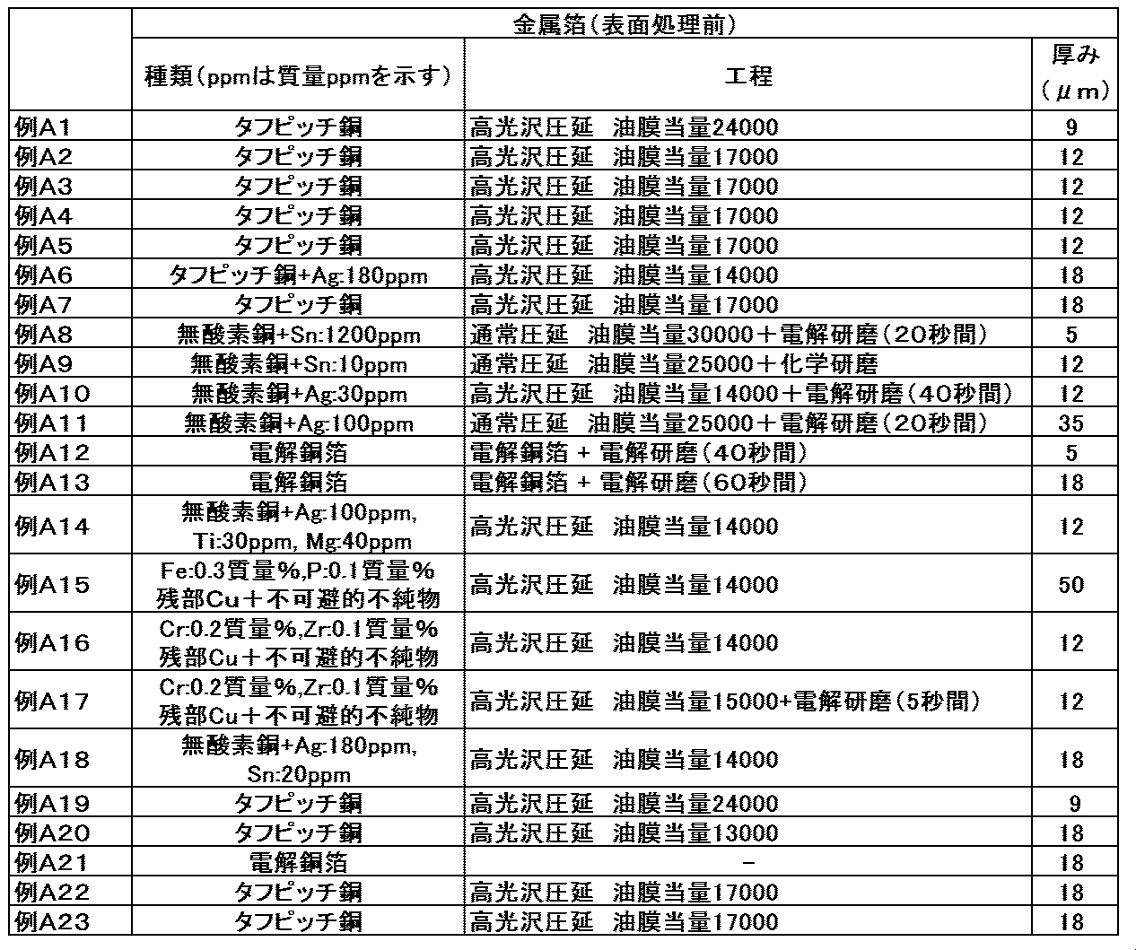
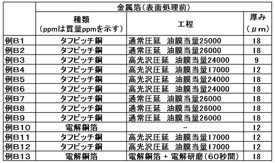
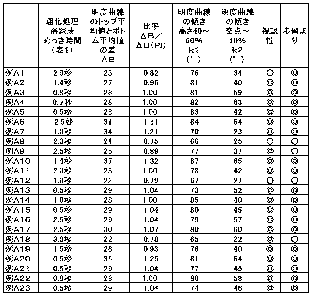
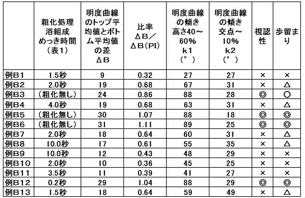
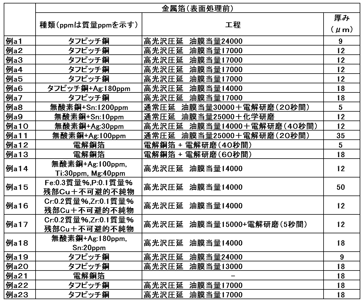
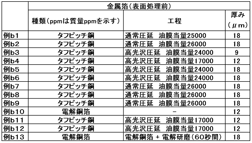
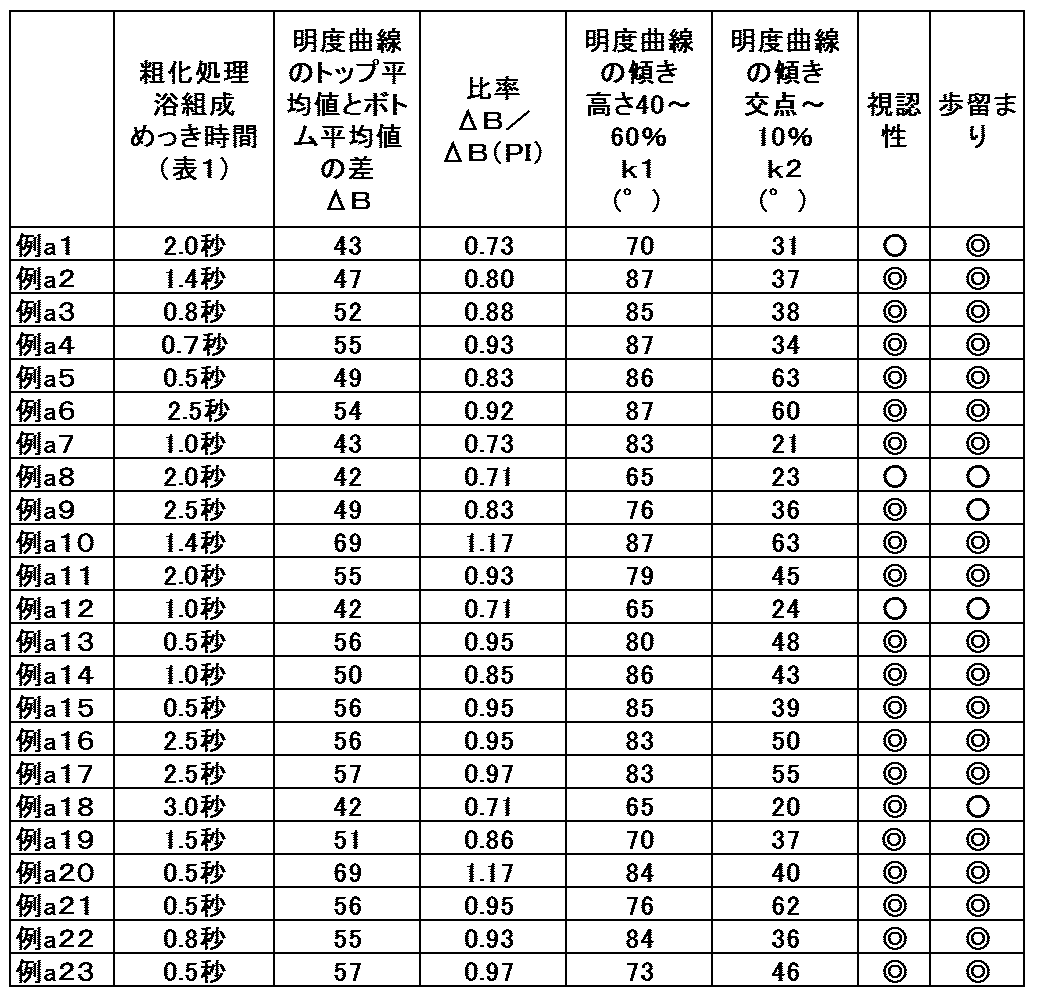
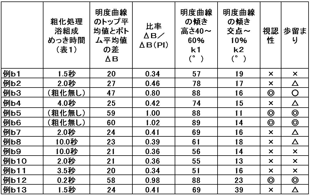
(評価結果)
例A1~例A23及び例B1~例B13、例a1~例a23及び例b1~例b13の各ポリイミド基材について、いずれも製造ラインで実際に製造することなく、実験室レベルで容易に且つ正確に視認性を評価することができた。
また、幅が1.0~2.0mmと大きいマークを上記例の代わりに用いて上記実施例と同様の試験を行ったところ、明度曲線として図3に示す底部のある図が得られた。図9に、マークの幅が1.0~2.0mmの場合の明度曲線の傾き評価の際の、撮影手段の構成及び明度曲線の傾きの測定方法を表す模式図を示す。この場合も、上記実施例と同じ結果が得られ、かつ上記実施例と同様に、ポリイミド基材について、製造ラインで実際に製造することなく、実験室レベルで容易に且つ正確に視認性を評価することができた。銅箔表面状態は、表中の視認性の評価の「◎」、「○」(以上合格)、「×」(不合格)をそのまま適用することで評価することで、銅箔の表面状態についても容易に且つ正確に評価することができた。
また、幅が1.0~2.0mmと大きいマークを上記例の代わりに用いて上記実施例と同様の試験を行ったところ、明度曲線として図3に示す底部のある図が得られた。図7に、マークの幅が1.0~2.0mmの場合の明度曲線の傾き評価の際の、撮影手段の構成及び明度曲線の傾きの測定方法を表す模式図を示す。この場合も、上記実施例と同じ結果が得られ、かつ上記実施例と同様に、製造ラインで実際に製造することなく、実験室レベルで容易に且つ正確にポリイミド基材の視認性を評価することができ、さらに銅箔の表面状態を評価することができた。
例A1~例A23及び例B1~例B13、例a1~例a23及び例b1~例b13の各ポリイミド基材について、いずれも製造ラインで実際に製造することなく、実験室レベルで容易に且つ正確に視認性を評価することができた。
また、幅が1.0~2.0mmと大きいマークを上記例の代わりに用いて上記実施例と同様の試験を行ったところ、明度曲線として図3に示す底部のある図が得られた。図9に、マークの幅が1.0~2.0mmの場合の明度曲線の傾き評価の際の、撮影手段の構成及び明度曲線の傾きの測定方法を表す模式図を示す。この場合も、上記実施例と同じ結果が得られ、かつ上記実施例と同様に、ポリイミド基材について、製造ラインで実際に製造することなく、実験室レベルで容易に且つ正確に視認性を評価することができた。銅箔表面状態は、表中の視認性の評価の「◎」、「○」(以上合格)、「×」(不合格)をそのまま適用することで評価することで、銅箔の表面状態についても容易に且つ正確に評価することができた。
また、幅が1.0~2.0mmと大きいマークを上記例の代わりに用いて上記実施例と同様の試験を行ったところ、明度曲線として図3に示す底部のある図が得られた。図7に、マークの幅が1.0~2.0mmの場合の明度曲線の傾き評価の際の、撮影手段の構成及び明度曲線の傾きの測定方法を表す模式図を示す。この場合も、上記実施例と同じ結果が得られ、かつ上記実施例と同様に、製造ラインで実際に製造することなく、実験室レベルで容易に且つ正確にポリイミド基材の視認性を評価することができ、さらに銅箔の表面状態を評価することができた。
10 透明基材の視認性評価装置
11 撮影手段
12 コンピュータ(観察地点-明度グラフ作製手段、視認性評価手段、スムージング処理手段)
13 表示手段
14 照明手段
15 ステージ
16 マーク
17 透明基材
20 積層体の位置決め装置
21 撮影手段
22 コンピュータ(観察地点-明度グラフ作製手段、位置決め手段、スムージング処理手段)
23 表示手段
24 照明手段
25 ステージ
26 マーク
27 積層体
10’ 銅箔の表面状態の評価装置
11’ 撮影手段
12’ コンピュータ(観察地点-明度グラフ作製手段、銅箔の表面状態評価手段、スムージング処理手段)
13’ 表示手段
14’ 照明手段
15’ ステージ
16’ マーク
17’ 透明基材
11 撮影手段
12 コンピュータ(観察地点-明度グラフ作製手段、視認性評価手段、スムージング処理手段)
13 表示手段
14 照明手段
15 ステージ
16 マーク
17 透明基材
20 積層体の位置決め装置
21 撮影手段
22 コンピュータ(観察地点-明度グラフ作製手段、位置決め手段、スムージング処理手段)
23 表示手段
24 照明手段
25 ステージ
26 マーク
27 積層体
10’ 銅箔の表面状態の評価装置
11’ 撮影手段
12’ コンピュータ(観察地点-明度グラフ作製手段、銅箔の表面状態評価手段、スムージング処理手段)
13’ 表示手段
14’ 照明手段
15’ ステージ
16’ マーク
17’ 透明基材
Claims (93)
- 透明基材の下に存在するマークを、前記透明基材越しに撮影する撮影手段と、
前記撮影によって得られた画像について、観察された前記マークが伸びる方向と交わる方向に沿って観察地点ごとの明度を測定して観察地点-明度グラフを作製する観察地点-明度グラフ作製手段と、
前記観察地点-明度グラフにおいて、前記マークの端部から前記マークがない部分にかけて生じる明度曲線の傾きに基づいて前記透明基材の視認性を評価する視認性評価手段と、
を備えた透明基材の視認性評価装置。 - 前記観察地点-明度グラフ作製手段が観察された前記マークが伸びる方向と垂直な方向に沿って観察地点ごとの明度を測定して観察地点-明度グラフを作製する請求項1に記載の透明基材の視認性評価装置。
- 前記視認性評価手段は、前記観察地点-明度グラフにおいて、前記マークの端部から前記マークがない部分にかけて生じる明度曲線の傾きを角度で表し、前記角度によって前記透明基材の視認性を評価する請求項1又は2に記載の透明基材の視認性評価装置。
- 前記撮影手段による撮影によって得られた画像について、明度のばらつきを緩和させるスムージング処理手段をさらに備え、
前記観察地点-明度グラフ作製手段が、前記スムージング処理後の前記明度を用いて観察地点-明度グラフを作製する請求項1~3のいずれか一項に記載の透明基材の視認性評価装置。 - 前記透明基材の下に存在するマークが、前記透明基材の下に敷いた印刷物に印刷されたライン状のマークであり、
前記観察地点-明度グラフ作製手段が、前記撮影によって得られた画像について、観察された前記ライン状のマークが伸びる方向と垂直な方向に沿って観察地点ごとの明度を測定して観察地点-明度グラフを作製する請求項1~4のいずれか一項に記載の透明基材の視認性評価装置。 - 前記透明基材は、少なくとも一方の表面が表面処理された表面処理金属箔を、表面処理された表面側から、前記透明基材の少なくとも一方の表面に貼り合わせた後、エッチングで前記金属箔を除去して作製されている請求項1~5のいずれか一項に記載の透明基材の視認性評価装置。
- 前記透明基材がポリイミド基板である請求項1~6のいずれか一項に記載の透明基材の視認性評価装置。
- 前記透明基材の厚さが50μmであり、且つ、前記金属箔に貼り合わせ前の透明基材についての前記マークの端部から前記マークがない部分にかけて生じる明度曲線のトップ平均値Btとボトム平均値Bbとの差ΔB(PI)〔ΔB(PI)=Bt-Bb〕が20以上33以下である請求項7に記載の透明基材の視認性評価装置。
- 前記透明基材の厚さが50μmであり、且つ、前記金属箔に貼り合わせ前の透明基材についての前記マークの端部から前記マークがない部分にかけて生じる明度曲線のトップ平均値Btとボトム平均値Bbとの差ΔB(PI)〔ΔB(PI)=Bt-Bb〕が50以上65以下である請求項7に記載の透明基材の視認性評価装置。
- 前記明度曲線の角度で表された傾きによる前記透明基材の視認性評価が、
前記表面処理金属箔を、表面処理された表面側から、前記透明基材の少なくとも一方の表面に貼り合わせた後、エッチングで前記金属箔を除去して作製された前記透明基材についての前記マークの端部から前記マークがない部分にかけて生じる明度曲線のトップ平均値Btとボトム平均値Bbとの差ΔB(ΔB=Bt-Bb)と、
ΔB/ΔB(PI)からなる比率と、
Btを基準とした所定の深さ範囲における前記明度曲線の角度で表された傾きと、
を用いて行う請求項7~9のいずれか一項に記載の透明基材の視認性評価装置。 - 前記Btを基準とした所定の深さ範囲における前記明度曲線の角度で表された傾きがBtを基準に0.4ΔB~0.6ΔBの深さ範囲における前記明度曲線の角度で表された傾きk1である請求項10に記載の透明基材の視認性評価装置。
- 前記明度曲線の角度で表された傾きによる前記透明基材の視認性評価が、
前記透明基材についての前記マークの端部から前記マークがない部分にかけて生じる明度曲線のトップ平均値Btとボトム平均値Bbとの差ΔB(ΔB=Bt-Bb)が20以上33以下、又は、50以上65以下であり、
ΔB/ΔB(PI)からなる比率が0.7以上であり、
Btを基準に0.4ΔB~0.6ΔBの深さ範囲における前記明度曲線の角度で表された傾きk1が65°以上となる場合を良好と判定する請求項11に記載の透明基材の視認性評価装置。 - 前記Btを基準に0.4ΔB~0.6ΔBの深さ範囲における前記明度曲線の角度で表された傾きk1が87°以下となる場合を更に良好と判定する請求項12に記載の透明基材の視認性評価装置。
- 前記明度曲線とBtとの交点からBtを基準に0.1ΔBまでの深さ範囲における前記明度曲線の角度で表された傾きk2をさらに評価に用いる請求項11~13のいずれか一項に記載の透明基材の視認性評価装置。
- 前記k2が30°以上となる場合を更に良好と判定する請求項14に記載の透明基材の視認性評価装置。
- コンピュータを請求項1~15のいずれか一項に記載の透明基材の視認性評価装置として機能させるためのプログラム。
- 請求項16に記載のプログラムが記録されたコンピュータ読み取り可能な記録媒体。
- 金属と樹脂との積層体の位置決めをするための積層体の位置決め装置であって、
マークを有する、前記金属と樹脂の積層体に対し、前記マークを前記樹脂越しに撮影する撮影手段と、
前記撮影によって得られた画像について、観察された前記マークが伸びる方向と交わる方向に沿って観察地点ごとの明度を測定して観察地点-明度グラフを作製する観察地点-明度グラフ作製手段と、
前記観察地点-明度グラフにおいて、前記マークの端部から前記マークがない部分にかけて生じる明度曲線の傾きによって前記積層体の位置を決定する位置決め手段と、
を備えた積層体の位置決め装置。 - 前記観察地点-明度グラフ作製手段は、観察された前記マークが伸びる方向と垂直な方向に沿って観察地点ごとの明度を測定して観察地点-明度グラフを作製する請求項18に記載の積層体の位置決め装置。
- 前記位置を決定した積層体の位置合わせを行う位置合わせ手段をさらに備えた請求項19に記載の積層体の位置決め装置。
- 前記金属と樹脂との積層体が、樹脂板及び前記樹脂板の上に設けられた回路を有するプリント配線板である請求項18~20のいずれか一項に記載の積層体の位置決め装置。
- 前記マークが前記回路である請求項21に記載の積層体の位置決め装置。
- コンピュータを請求項18~22のいずれか一項に記載の積層体の位置決め装置として機能させるためのプログラム。
- 請求項23に記載のプログラムが記録されたコンピュータ読み取り可能な記録媒体。
- 請求項21又は22に記載の位置決め装置を用いて、プリント配線板の位置決めを行い、位置決めされた前記プリント配線板に部品を装着する工程を含むプリント配線板の製造方法。
- 請求項21又は22に記載の位置決め装置を用いて、プリント配線板の位置決めを行い、位置決めされた前記プリント配線板の位置合わせを行い、位置合わせされた前記プリント配線板に部品を装着する工程を含むプリント配線板の製造方法。
- 請求項21又は22に記載の位置決め装置を用いて、プリント配線板の位置決めを行い、位置決めされた前記プリント配線板にもう一つのプリント配線板を接続する工程を含むプリント配線板の製造方法。
- 請求項21又は22に記載の位置決め装置を用いて、プリント配線板の位置決めを行い、位置決めされた前記プリント配線板の位置合わせを行い、位置合わせされた前記プリント配線板にもう一つのプリント配線板を接続する工程を含むプリント配線板の製造方法。
- 金属箔を透明基材の少なくとも一方の面に張り合わせた後に、前記金属箔をエッチングにより除去し、当該金属箔をエッチングにより除去した後の透明基材の下に存在するマークを、前記透明基材越しに撮影する撮影手段と、
前記撮影によって得られた画像について、観察された前記マークが伸びる方向と交わる方向に沿って観察地点ごとの明度を測定して観察地点-明度グラフを作製する観察地点-明度グラフ作製手段と、
前記観察地点-明度グラフにおいて、前記マークの端部から前記マークがない部分にかけて生じる明度曲線の傾きに基づいて前記透明基材の視認性を評価し、前記視認性の評価結果に基づいて金属箔の表面状態を評価する金属箔表面状態評価手段と、
を備えた金属箔の表面状態の評価装置。 - 前記観察地点-明度グラフ作製手段は、前記撮影によって得られた画像について、観察された前記マークが伸びる方向と垂直な方向に沿って観察地点ごとの明度を測定して観察地点-明度グラフを作製する請求項29に記載の金属箔の表面状態の評価装置。
- 前記金属箔が銅箔である請求項29又は30に記載の金属箔の表面状態の評価装置。
- 表面処理金属箔の表面処理された表面側を透明基材の少なくとも一方の面に張り合わせた後に、前記表面処理金属箔をエッチングにより除去し、当該表面処理金属箔をエッチングにより除去した後の透明基材の下に存在するマークを、前記透明基材越しに撮影する撮影手段と、
前記撮影によって得られた画像について、観察された前記マークが伸びる方向と垂直な方向に沿って観察地点ごとの明度を測定して観察地点-明度グラフを作製する観察地点-明度グラフ作製手段と、
前記観察地点-明度グラフにおいて、前記マークの端部から前記マークがない部分にかけて生じる明度曲線の傾きに基づいて前記透明基材の視認性を評価し、前記視認性の評価結果に基づいて金属箔の表面状態を評価する金属箔表面状態評価手段と、
を備えた金属箔の表面状態の評価装置。 - 前記金属箔表面状態評価手段は、前記観察地点-明度グラフにおいて、前記マークの端部から前記マークがない部分にかけて生じる明度曲線の傾きを角度で表し、前記角度によって前記透明基材の視認性を評価し、前記視認性の評価結果に基づいて金属箔の表面状態を評価する請求項32に記載の金属箔の表面状態の評価装置。
- 前記撮影手段による撮影によって得られた画像について、明度のばらつきを緩和させるスムージング処理手段をさらに備え、
前記観察地点-明度グラフ作製手段が、前記スムージング処理後の前記明度を用いて観察地点-明度グラフを作製する請求項32又は33に記載の金属箔の表面状態の評価装置。 - 前記透明基材の下に存在するマークが、前記透明基材の下に敷いた印刷物に印刷されたライン状のマークであり、
前記観察地点-明度グラフ作製手段が、前記撮影によって得られた画像について、観察された前記ライン状のマークが伸びる方向と垂直な方向に沿って観察地点ごとの明度を測定して観察地点-明度グラフを作製する請求項32~34のいずれか一項に記載の金属箔の表面状態の評価装置。 - 前記透明基材がポリイミド基板である請求項32~35のいずれか一項に記載の金属箔の表面状態の評価装置。
- 前記透明基材の厚さが50μmであり、且つ、前記金属箔に貼り合わせ前の透明基材についての前記マークの端部から前記マークがない部分にかけて生じる明度曲線のトップ平均値Btとボトム平均値Bbとの差ΔB(PI)〔ΔB(PI)=Bt-Bb〕が20以上33以下である請求項36に記載の金属箔の表面状態の評価装置。
- 前記透明基材の厚さが50μmであり、且つ、前記金属箔に貼り合わせ前の透明基材についての前記マークの端部から前記マークがない部分にかけて生じる明度曲線のトップ平均値Btとボトム平均値Bbとの差ΔB(PI)〔ΔB(PI)=Bt-Bb〕が50以上65以下である請求項36に記載の金属箔の表面状態の評価装置。
- 前記明度曲線の角度で表された傾きによる前記透明基材の視認性評価が、
前記表面処理金属箔を、表面処理された表面側から、前記透明基材の少なくとも一方の表面に貼り合わせた後、エッチングで前記金属箔を除去して作製された前記透明基材についての前記マークの端部から前記マークがない部分にかけて生じる明度曲線のトップ平均値Btとボトム平均値Bbとの差ΔB(ΔB=Bt-Bb)と、
ΔB/ΔB(PI)からなる比率と、
Btを基準とした所定の深さ範囲における前記明度曲線の角度で表された傾きと、
を用いて行う請求項36~38のいずれか一項に記載の金属箔の表面状態の評価装置。 - 前記Btを基準とした所定の深さ範囲における前記明度曲線の角度で表された傾きがBtを基準に0.4ΔB~0.6ΔBの深さ範囲における前記明度曲線の角度で表された傾きk1である請求項39に記載の金属箔の表面状態の評価装置。
- 前記明度曲線の角度で表された傾きによる前記透明基材の視認性評価が、
前記透明基材についての前記マークの端部から前記マークがない部分にかけて生じる明度曲線のトップ平均値Btとボトム平均値Bbとの差ΔB(ΔB=Bt-Bb)が20以上33以下、又は、50以上65以下であり、
ΔB/ΔB(PI)からなる比率が0.7以上であり、
Btを基準に0.4ΔB~0.6ΔBの深さ範囲における前記明度曲線の角度で表された傾きk1が65°以上となる場合を良好と判定する請求項40に記載の金属箔の表面状態の評価装置。 - 前記Btを基準に0.4ΔB~0.6ΔBの深さ範囲における前記明度曲線の角度で表された傾きk1が87°以下となる場合を更に良好と判定する請求項41に記載の金属箔の表面状態の評価装置。
- 前記明度曲線とBtとの交点からBtを基準に0.1ΔBまでの深さ範囲における前記明度曲線の角度で表された傾きk2をさらに評価に用いる請求項40~42のいずれか一項に記載の金属箔の表面状態の評価装置。
- 前記k2が30°以上となる場合を更に良好と判定する請求項43に記載の金属箔の表面状態の評価装置。
- 前記金属箔が銅箔である請求項32~44のいずれか一項に記載の金属箔の表面状態の評価装置。
- コンピュータを請求項32~45のいずれか一項に記載の金属箔の表面状態の評価装置として機能させるためのプログラム。
- 請求項46に記載のプログラムが記録されたコンピュータ読み取り可能な記録媒体。
- 表面処理金属箔の表面処理された表面側を透明基材の少なくとも一方の面に張り合わせた後に、前記表面処理金属箔をエッチングにより除去し、当該表面処理金属箔をエッチングにより除去した後の透明基材の下に存在するマークを、前記透明基材越しに撮影し、
前記撮影によって得られた画像について、観察された前記マークが伸びる方向と垂直な方向に沿って観察地点ごとの明度を測定して観察地点-明度グラフを作製し、
前記観察地点-明度グラフにおいて、前記マークの端部から前記マークがない部分にかけて生じる明度曲線の傾きを角度に基づいて前記透明基材の視認性を評価し、前記視認性の評価結果に基づいて金属箔の表面状態を評価する金属箔の表面状態の評価方法。 - 前記表面処理金属箔が表面処理銅箔である請求項48に記載の金属箔の表面状態の評価方法。
- 前記観察地点-明度グラフを、前記撮影によって得られた画像について、観察された前記マークが伸びる方向と垂直な方向に沿って観察地点ごとの明度を測定して作製する請求項48又は49に記載の金属箔の表面状態の評価方法。
- 前記観察地点-明度グラフにおいて、前記マークの端部から前記マークがない部分にかけて生じる明度曲線の傾きを角度で表し、前記角度によって前記透明基材の視認性を評価し、前記視認性の評価結果に基づいて金属の表面状態を評価する請求項48~50のいずれか一項に記載の金属箔の表面状態の評価方法。
- マーク及び前記マーク上に設けた透明基材を準備し、前記マークを前記透明基材越しにCCDカメラで撮影し、
前記撮影によって得られた画像について、観察された前記マークを横切る方向に沿って観察地点ごとの明度を測定して観察地点-明度グラフを作成し、
前記観察地点-明度グラフにおいて、前記マークの端部から前記マークがない部分にかけて生じる明度曲線の傾きに基づいて前記透明基材の視認性を評価する方法。 - 前記観察地点-明度グラフにおいて、前記マークの端部から前記マークがない部分にかけて生じる明度曲線の傾きを角度で表し、前記角度によって前記透明基材の視認性を評価する請求項52に記載の評価方法。
- 前記撮影によって得られた画像について、明度のばらつきをスムージング処理によって緩和させ、前記スムージング処理後の前記明度を用いて観察地点-明度グラフを作成する請求項52又は53に記載の評価方法。
- 前記マークがライン状のマークであり、
前記観察地点-明度グラフが、前記撮影によって得られた画像について、観察された前記ライン状のマークが伸びる方向と垂直な方向に沿って観察地点ごとの明度を測定して作成される請求項52~54のいずれか一項に記載の評価方法。 - 前記透明基材は、前記マーク上に設ける前に、少なくとも一方の表面が粗化処理された表面処理金属箔を、粗化処理表面側から、前記透明基材の少なくとも一方の表面に貼り合わせた後、エッチングで前記金属箔を除去して作製されている請求項52~55のいずれか一項に記載の評価方法。
- 前記透明基材は、前記マーク上に設ける前に、少なくとも一方の表面が粗化処理された表面処理金属箔を、粗化処理表面側から、前記透明基材の両面に貼り合わせた後、エッチングで前記両面の金属箔を除去して作製されている請求項56に記載の評価方法。
- 前記粗化処理が、前記金属箔表面に粗化粒子を形成する処理である請求項56又は57に記載の評価方法。
- 前記金属箔が銅箔である請求項55~57のいずれか一項に記載の評価方法。
- 前記透明基材がポリイミド基板である請求項52~59のいずれか一項に記載の評価方法。
- 前記透明基材が、厚さ50μmであり、且つ、前記金属箔に貼り合わせ前の透明基材についての前記マークの端部から前記マークがない部分にかけて生じる明度曲線のトップ平均値Btとボトム平均値Bbとの差ΔB(PI)〔ΔB(PI)=Bt-Bb〕が20以上33以下である請求項60に記載の評価方法。
- 前記透明基材の視認性を評価する方法が、前記表面処理金属箔を、粗化処理表面側から、前記透明基材の少なくとも一方の表面に貼り合わせた後、エッチングで前記金属箔を除去して作製された前記透明基材についての前記マークの端部から前記マークがない部分にかけて生じる明度曲線のトップ平均値Btとボトム平均値Bbとの差ΔB(ΔB=Bt-Bb)と、
ΔB/ΔB(PI)からなる比率と、
Btを基準とした所定の深さ範囲における前記明度曲線の角度で表された傾きと、
を用いて行う請求項61に記載の評価方法。 - 前記Btを基準とした所定の深さ範囲における前記明度曲線の角度で表された傾きがBtを基準に0.4ΔB~0.6ΔBの深さ範囲における前記明度曲線の角度で表された傾きk1である請求項62に記載の評価方法。
- 前記透明基材の視認性を評価する方法が、前記マークの端部から前記マークがない部分にかけて生じる明度曲線のトップ平均値Btとボトム平均値Bbとの差ΔB(ΔB=Bt-Bb)が20以上33以下であり、
ΔB/ΔB(PI)からなる比率が0.7以上であり、
Btを基準に0.4ΔB~0.6ΔBの深さ範囲における前記明度曲線の角度で表された傾きk1が65°以上となる場合を良好と判定する請求項63に記載の評価方法。 - 前記k1が87°以下となる場合を更に良好と判定する請求項64に記載の評価方法。
- 前記撮影によって得られた画像から作成した観察地点-明度グラフにおいて、明度曲線とBtとの交点からBtを基準に0.1ΔBまでの深さ範囲における前記明度曲線の角度で表された傾きk2をさらに評価に用いる請求項61~65のいずれか一項に記載の評価方法。
- 前記k2が30°以上となる場合を更に良好と判定する請求項66に記載の評価方法。
- 金属と樹脂との積層体の位置決めをする方法であって、
前記金属と樹脂の積層体はマークを有し、
前記マークを前記樹脂越しにCCDカメラで撮影し、
前記撮影によって得られた画像について、観察された前記マークを横切る方向に沿って観察地点ごとの明度を測定して観察地点-明度グラフを作成し、
前記観察地点-明度グラフにおいて、前記マークの端部から前記マークがない部分にかけて生じる明度曲線の傾きに基づいて金属と樹脂との積層体の位置決めをする方法。 - 前記観察地点-明度グラフにおいて、前記マークの端部から前記マークがない部分にかけて生じる明度曲線の傾きを角度で表し、前記角度が所定の値以上となる場合に、前記角度を測定した位置に基づいて金属と樹脂との積層体の位置決めをする請求項68に記載の位置決め方法。
- 請求項68又は69に記載の位置決め方法を用いて、プリント配線板の位置決めを行い、位置決めされた前記プリント配線板に部品を装着する工程を含むプリント配線板の製造方法。
- 請求項68又は69に記載の位置決め方法を用いて、プリント配線板の位置決めを行い、位置決めされた前記プリント配線板の位置合わせを行い、位置合わせされた前記プリント配線板に部品を装着する工程を含むプリント配線板の製造方法。
- 請求項68又は69に記載の位置決め方法を用いて、プリント配線板の位置決めを行い、位置決めされた前記プリント配線板にもう一つのプリント配線板を接続する工程を含むプリント配線板の製造方法。
- 請求項68又は69に記載の位置決め方法を用いて、プリント配線板の位置決めを行い、位置決めされた前記プリント配線板の位置合わせを行い、位置合わせされた前記プリント配線板にもう一つのプリント配線板を接続する工程を含むプリント配線板の製造方法。
- 金属と透明基材との積層体が有するマークが存在するか否かを判定する方法であって、
マークを有する、前記金属と透明基材との積層体に対し、前記マークを前記透明基材越しに撮影し、
前記撮影によって得られた画像について、観察された前記マークが伸びる方向と交わる方向に沿って観察地点ごとの明度を測定して観察地点-明度グラフを作成し、
前記観察地点-明度グラフにおいて、前記マークの端部から前記マークがない部分にかけて生じる明度曲線の傾きに基づいて前記積層体が有するマークが存在するか否かを判定する方法。 - 前記観察地点-明度グラフを、前記撮影によって得られた画像について、観察された前記マークが伸びる方向と垂直な方向に沿って観察地点ごとの明度を測定して作成する請求項74に記載のマークが存在するか否かを判定する方法。
- 前記観察地点-明度グラフにおいて、前記マークの端部から前記マークがない部分にかけて生じる明度曲線の傾きを角度で表し、前記角度が所定の値以上となる場合に、前記積層体が有するマークが存在すると判定する請求項74又は75に記載のマークが存在するか否かを判定する方法。
- 前記マークが、前記透明基材の板及び前記透明基材の板の上に設けられた回路である請求項74~76のいずれか一項に記載のマークが存在するか否かを判定する方法。
- 金属と透明基材との積層体が有するマークが存在するか否かを判定する装置であって、
マークを有する、前記金属と透明基材の積層体に対し、前記マークを前記透明基材越しに撮影する撮影手段と、
前記撮影によって得られた画像について、観察された前記マークが伸びる方向と交わる方向に沿って観察地点ごとの明度を測定して観察地点-明度グラフを作製する観察地点-明度グラフ作製手段と、
前記観察地点-明度グラフにおいて、前記マークの端部から前記マークがない部分にかけて生じる明度曲線の傾きに基づいて前記マークが存在するか否かを判定する判定手段と、
を備えた、金属と透明基材との積層体が有するマークが存在するか否かを判定する装置。 - 前記観察地点-明度グラフ作製手段は、前記前記撮影によって得られた画像について、観察された前記マークが伸びる方向と垂直な方向に沿って観察地点ごとの明度を測定して観察地点-明度グラフを作成する請求項78に記載の金属と透明基材との積層体が有するマークが存在するか否かを判定する装置。
- 前記マークが存在するか否かを判定する判定手段は、前記観察地点-明度グラフにおいて、前記マークの端部から前記マークがない部分にかけて生じる明度曲線の傾きを角度で表し、前記角度が所定の値以上となる場合に、前記積層体が有するマークが存在すると判定する請求項78又は79に記載の金属と透明基材との積層体が有するマークが存在するか否かを判定する装置。
- 前記マークが、前記透明基材の板及び前記透明基材の板の上に設けられた回路である請求項78~80のいずれか一項に記載の金属と透明基材との積層体が有するマークが存在するか否かを判定する装置。
- コンピュータを請求項78~81のいずれか一項に記載の判定装置として機能させるためのプログラム。
- 請求項82に記載のプログラムが記録されたコンピュータ読み取り可能な記録媒体。
- 金属と透明基材との積層体が有するマークの位置を検出する方法であって、
マークを有する、前記金属と透明基材との積層体に対し、前記マークを前記透明基材越しに撮影し、
前記撮影によって得られた画像について、観察された前記マークが伸びる方向と交わる方向に沿って観察地点ごとの明度を測定して観察地点-明度グラフを作成し、
前記観察地点-明度グラフにおいて、前記マークの端部から前記マークがない部分にかけて生じる明度曲線の傾きに基づいて前記マークの位置を検出する方法。 - 観察地点-明度グラフを、前記撮影によって得られた画像について、観察された前記マークが伸びる方向と垂直な方向に沿って観察地点ごとの明度を測定して作成する請求項84に記載のマークの位置を検出する方法。
- 前記観察地点-明度グラフにおいて、前記マークの端部から前記マークがない部分にかけて生じる明度曲線の傾きを角度で表し、前記角度が所定の値以上となる場合に、前記角度を測定した位置に基づいて前記マークの位置を検出する請求項84又は85に記載のマークの位置を検出する方法。
- 前記マークが、前記透明基材の板及び前記透明基材の板の上に設けられた回路である請求項84~86のいずれか一項に記載のマークの位置を検出する方法。
- 金属と透明基材との積層体が有するマークの位置を検出する装置であって、
マークを有する、前記金属と透明基材の積層体に対し、前記マークを前記透明基材越しに撮影する撮影手段と、
前記撮影によって得られた画像について、観察された前記マークが伸びる方向と交わる方向に沿って観察地点ごとの明度を測定して観察地点-明度グラフを作成する観察地点-明度グラフ作製手段と、
前記観察地点-明度グラフにおいて、前記マークの端部から前記マークがない部分にかけて生じる明度曲線の傾きに基づいて前記マークの位置を検出する位置検出手段と、
を備えた、金属と透明基材との積層体が有するマークの位置を検出する装置。 - 前記観察地点-明度グラフ作製手段は、前記撮影によって得られた画像について、観察された前記マークが伸びる方向と垂直な方向に沿って観察地点ごとの明度を測定して観察地点-明度グラフを作成する請求項88に記載の金属と透明基材との積層体が有するマークの位置を検出する装置。
- 前記観察地点-明度グラフにおいて、前記マークの端部から前記マークがない部分にかけて生じる明度曲線の傾きを角度で表し、前記角度が所定の値以上となる場合に、前記角度を測定した位置に基づいて前記マークの位置を検出する請求項88又は89に記載の金属と透明基材との積層体が有するマークの位置を検出する装置。
- 前記マークが、前記透明基材の板及び前記透明基材の板の上に設けられた回路である請求項88~90のいずれか一項に記載の金属と透明基材との積層体が有するマークの位置を検出する装置。
- コンピュータを請求項88~91のいずれかに記載の検出装置として機能させるためのプログラム。
- 請求項92に記載のプログラムが記録されたコンピュータ読み取り可能な記録媒体。
Priority Applications (1)
| Application Number | Priority Date | Filing Date | Title |
|---|---|---|---|
| JP2014516817A JP5824147B2 (ja) | 2012-05-21 | 2013-05-21 | 透明基材の視認性評価装置、積層体の位置決め装置、判定装置、位置検出装置、金属箔の表面状態の評価装置、プログラム、記録媒体、プリント配線板の製造方法、透明基材の視認性評価方法、積層体の位置決め方法、判定方法、位置検出方法 |
Applications Claiming Priority (8)
| Application Number | Priority Date | Filing Date | Title |
|---|---|---|---|
| JP2012129315 | 2012-05-21 | ||
| JP2012-129315 | 2012-05-21 | ||
| JP2012132954 | 2012-06-12 | ||
| JP2012-132954 | 2012-06-12 | ||
| JP2012-250736 | 2012-11-14 | ||
| JP2012-250735 | 2012-11-14 | ||
| JP2012250735 | 2012-11-14 | ||
| JP2012250736 | 2012-11-14 |
Publications (1)
| Publication Number | Publication Date |
|---|---|
| WO2013176148A1 true WO2013176148A1 (ja) | 2013-11-28 |
Family
ID=49623836
Family Applications (1)
| Application Number | Title | Priority Date | Filing Date |
|---|---|---|---|
| PCT/JP2013/064122 Ceased WO2013176148A1 (ja) | 2012-05-21 | 2013-05-21 | 透明基材の視認性評価装置、積層体の位置決め装置、判定装置、位置検出装置、金属箔の表面状態の評価装置、プログラム、記録媒体、プリント配線板の製造方法、透明基材の視認性評価方法、積層体の位置決め方法、判定方法、位置検出方法 |
Country Status (3)
| Country | Link |
|---|---|
| JP (1) | JP5824147B2 (ja) |
| TW (1) | TW201411112A (ja) |
| WO (1) | WO2013176148A1 (ja) |
Cited By (1)
| Publication number | Priority date | Publication date | Assignee | Title |
|---|---|---|---|---|
| CN114269078A (zh) * | 2021-12-28 | 2022-04-01 | 深圳市深合达电子有限公司 | 一种用于印刷电路板生产的压合机 |
Families Citing this family (1)
| Publication number | Priority date | Publication date | Assignee | Title |
|---|---|---|---|---|
| CN114993232B (zh) * | 2022-07-18 | 2022-10-18 | 苏州宇量电池有限公司 | 一种电极材料形貌的检测方法 |
Citations (6)
| Publication number | Priority date | Publication date | Assignee | Title |
|---|---|---|---|---|
| JPH0618414A (ja) * | 1992-03-03 | 1994-01-25 | Saint Gobain Vitrage Internatl | 積層窓ガラスの透明度を監視するための方法と装置 |
| JP2003309336A (ja) * | 2002-04-15 | 2003-10-31 | Toray Ind Inc | フレキシブルプリント基板用積層板およびフレキシブルプリント基板 |
| JP2004119961A (ja) * | 2002-09-02 | 2004-04-15 | Furukawa Techno Research Kk | チップオンフィルム用、プラズマディスプレイ用、または高周波プリント配線板用銅箔 |
| JP2006001056A (ja) * | 2004-06-15 | 2006-01-05 | Asahi Glass Co Ltd | 輸送機材用防曇性窓用板状体 |
| JP2006253185A (ja) * | 2005-03-08 | 2006-09-21 | Toray Ind Inc | ポリイミドフィルム、及びこれを用いた耐熱性樹脂積層フィルム、金属層付き積層フィルム |
| WO2011152178A1 (ja) * | 2010-05-31 | 2011-12-08 | 東洋紡績株式会社 | フレキシブル金属張積層体 |
Family Cites Families (1)
| Publication number | Priority date | Publication date | Assignee | Title |
|---|---|---|---|---|
| US5700550A (en) * | 1993-12-27 | 1997-12-23 | Toppan Printing Co., Ltd. | Transparent hologram seal |
-
2013
- 2013-05-21 JP JP2014516817A patent/JP5824147B2/ja active Active
- 2013-05-21 TW TW102117988A patent/TW201411112A/zh unknown
- 2013-05-21 WO PCT/JP2013/064122 patent/WO2013176148A1/ja not_active Ceased
Patent Citations (6)
| Publication number | Priority date | Publication date | Assignee | Title |
|---|---|---|---|---|
| JPH0618414A (ja) * | 1992-03-03 | 1994-01-25 | Saint Gobain Vitrage Internatl | 積層窓ガラスの透明度を監視するための方法と装置 |
| JP2003309336A (ja) * | 2002-04-15 | 2003-10-31 | Toray Ind Inc | フレキシブルプリント基板用積層板およびフレキシブルプリント基板 |
| JP2004119961A (ja) * | 2002-09-02 | 2004-04-15 | Furukawa Techno Research Kk | チップオンフィルム用、プラズマディスプレイ用、または高周波プリント配線板用銅箔 |
| JP2006001056A (ja) * | 2004-06-15 | 2006-01-05 | Asahi Glass Co Ltd | 輸送機材用防曇性窓用板状体 |
| JP2006253185A (ja) * | 2005-03-08 | 2006-09-21 | Toray Ind Inc | ポリイミドフィルム、及びこれを用いた耐熱性樹脂積層フィルム、金属層付き積層フィルム |
| WO2011152178A1 (ja) * | 2010-05-31 | 2011-12-08 | 東洋紡績株式会社 | フレキシブル金属張積層体 |
Non-Patent Citations (1)
| Title |
|---|
| TOSHIAKI SUZUKI ET AL.: "COF Yoto Oyobi Ko Kukkyoku FPC Yoto Denkai Dohaku 'U-WZ-haku'", ELECTRONIC MATERIALS AND PARTS, vol. 45, no. 10, 1 October 2006 (2006-10-01), pages 35 - 38 * |
Cited By (2)
| Publication number | Priority date | Publication date | Assignee | Title |
|---|---|---|---|---|
| CN114269078A (zh) * | 2021-12-28 | 2022-04-01 | 深圳市深合达电子有限公司 | 一种用于印刷电路板生产的压合机 |
| CN114269078B (zh) * | 2021-12-28 | 2024-04-26 | 深圳市大正科技有限公司 | 一种用于印刷电路板生产的压合机 |
Also Published As
| Publication number | Publication date |
|---|---|
| TW201411112A (zh) | 2014-03-16 |
| JP5824147B2 (ja) | 2015-11-25 |
| JPWO2013176148A1 (ja) | 2016-01-14 |
Similar Documents
| Publication | Publication Date | Title |
|---|---|---|
| CN103946426B (zh) | 表面处理铜箔、使用了它的层叠板、印刷布线板以及覆铜板 | |
| TWI477389B (zh) | Surface treatment of copper foil and the use of its laminated board | |
| JP6393126B2 (ja) | 表面処理圧延銅箔、積層板、プリント配線板、電子機器及びプリント配線板の製造方法 | |
| JP6497881B2 (ja) | 圧延銅箔、それを用いた銅張積層板、プリント配線板、電子機器、回路接続部材の製造方法及び回路接続部材 | |
| WO2015087941A1 (ja) | 表面処理銅箔、銅張積層板、プリント配線板、電子機器及びプリント配線板の製造方法 | |
| JP5362923B1 (ja) | 表面処理銅箔及びそれを用いた積層板 | |
| JP5362922B1 (ja) | 表面処理銅箔及びそれを用いた積層板 | |
| JP5362899B1 (ja) | 表面処理銅箔及びそれを用いた積層板 | |
| JP6205121B2 (ja) | 透明基材の視認性評価方法、積層体の位置決め方法、及び、プリント配線板の製造方法 | |
| TWI503062B (zh) | Surface treatment of copper foil and the use of its laminated board, printed wiring board, electronic equipment and manufacturing printed wiring board method | |
| JP5432357B1 (ja) | 表面処理銅箔及びそれを用いた積層板、銅張積層板、プリント配線板並びに電子機器 | |
| JP6205120B2 (ja) | 透明基材の視認性評価装置、透明基材の視認性評価プログラム及びそれが記録されたコンピュータ読み取り可能な記録媒体、並びに、積層体の位置決め装置、積層体の位置決めプログラム及びそれが記録されたコンピュータ読み取り可能な記録媒体、及び、プリント配線板の製造方法 | |
| JP6305001B2 (ja) | 銅箔、銅張積層板及びフレキシブルプリント配線板 | |
| JP5269247B1 (ja) | 金属材料の表面状態の評価装置、金属材料の表面状態の評価プログラム及びそれが記録されたコンピュータ読み取り可能な記録媒体、並びに、金属材料の表面状態の評価方法 | |
| JP5824147B2 (ja) | 透明基材の視認性評価装置、積層体の位置決め装置、判定装置、位置検出装置、金属箔の表面状態の評価装置、プログラム、記録媒体、プリント配線板の製造方法、透明基材の視認性評価方法、積層体の位置決め方法、判定方法、位置検出方法 | |
| JP2014065974A (ja) | 表面処理銅箔及びそれを用いた積層板、銅張積層板、プリント配線板並びに電子機器 | |
| WO2014042256A1 (ja) | 金属材料の表面状態の評価装置、透明基材の視認性評価装置、その評価プログラム及びそれが記録されたコンピュータ読み取り可能な記録媒体 | |
| JP5337907B1 (ja) | 透明基材の視認性評価装置、透明基材の視認性評価プログラム及びそれが記録されたコンピュータ読み取り可能な記録媒体、積層体の位置決め装置、積層体の位置決めプログラム及びそれが記録されたコンピュータ読み取り可能な記録媒体、金属と透明基材との積層体が有するマークが存在するか否かを判定する装置及び判定プログラム及びそれが記録されたコンピュータ読み取り可能な記録媒体、並びに、金属と透明基材との積層体が有するマークの位置を検出する装置及び検出プログラム及びそれが記録されたコンピュータ読み取り可能な記録媒体 | |
| JP5323248B1 (ja) | 透明基材の視認性評価方法及び積層体の位置決め方法 | |
| CN105980609B (zh) | 表面处理铜箔、覆铜积层板、印刷配线板、电子机器及印刷配线板的制造方法 |
Legal Events
| Date | Code | Title | Description |
|---|---|---|---|
| 121 | Ep: the epo has been informed by wipo that ep was designated in this application |
Ref document number: 13793656 Country of ref document: EP Kind code of ref document: A1 |
|
| ENP | Entry into the national phase |
Ref document number: 2014516817 Country of ref document: JP Kind code of ref document: A |
|
| NENP | Non-entry into the national phase |
Ref country code: DE |
|
| 122 | Ep: pct application non-entry in european phase |
Ref document number: 13793656 Country of ref document: EP Kind code of ref document: A1 |