WO2013175750A1 - Motor - Google Patents
Motor Download PDFInfo
- Publication number
- WO2013175750A1 WO2013175750A1 PCT/JP2013/003162 JP2013003162W WO2013175750A1 WO 2013175750 A1 WO2013175750 A1 WO 2013175750A1 JP 2013003162 W JP2013003162 W JP 2013003162W WO 2013175750 A1 WO2013175750 A1 WO 2013175750A1
- Authority
- WO
- WIPO (PCT)
- Prior art keywords
- wall portion
- rear wall
- circumferential
- back cover
- brush card
- Prior art date
- Legal status (The legal status is an assumption and is not a legal conclusion. Google has not performed a legal analysis and makes no representation as to the accuracy of the status listed.)
- Ceased
Links
Images


Classifications
-
- H—ELECTRICITY
- H02—GENERATION; CONVERSION OR DISTRIBUTION OF ELECTRIC POWER
- H02K—DYNAMO-ELECTRIC MACHINES
- H02K5/00—Casings; Enclosures; Supports
- H02K5/04—Casings or enclosures characterised by the shape, form or construction thereof
- H02K5/14—Means for supporting or protecting brushes or brush holders
-
- H—ELECTRICITY
- H02—GENERATION; CONVERSION OR DISTRIBUTION OF ELECTRIC POWER
- H02K—DYNAMO-ELECTRIC MACHINES
- H02K5/00—Casings; Enclosures; Supports
- H02K5/04—Casings or enclosures characterised by the shape, form or construction thereof
- H02K5/10—Casings or enclosures characterised by the shape, form or construction thereof with arrangements for protection from ingress, e.g. water or fingers
-
- H—ELECTRICITY
- H02—GENERATION; CONVERSION OR DISTRIBUTION OF ELECTRIC POWER
- H02K—DYNAMO-ELECTRIC MACHINES
- H02K5/00—Casings; Enclosures; Supports
- H02K5/04—Casings or enclosures characterised by the shape, form or construction thereof
- H02K5/14—Means for supporting or protecting brushes or brush holders
- H02K5/143—Means for supporting or protecting brushes or brush holders for cooperation with commutators
- H02K5/148—Slidably supported brushes
-
- H—ELECTRICITY
- H02—GENERATION; CONVERSION OR DISTRIBUTION OF ELECTRIC POWER
- H02K—DYNAMO-ELECTRIC MACHINES
- H02K2205/00—Specific aspects not provided for in the other groups of this subclass relating to casings, enclosures, supports
- H02K2205/09—Machines characterised by drain passages or by venting, breathing or pressure compensating means
Definitions
- the present invention relates to a motor.
- a motor having a brush has been known.
- the structure of a motor having a brush is described in, for example, Japanese Patent Publication No. 3971349.
- the motor in the publication includes a rotatable armature and a brush which is in sliding contact with a commutator of the armature (Paragraphs 0018 to 0019).
- the brush in the publication is connected to an external power source, and supplies electric power to the armature via the commutator (paragraph 0019).
- the motor having the brush is used in an environment in which liquid droplets are likely to be present, for example, the inside of a vehicle.
- liquid droplets be prevented from, at least, adhering to the brush which is a conductor.
- it is necessary to efficiently discharge the droplet from the inside of a cover which accommodates the brush.
- a brush card that supports the brush is disposed inside the cover, it is necessary to secure drainage so that the droplet does not remain in the brush card.
- An object of the present invention is to provide, in a motor having a brush, a structure capable of efficiently discharging liquid droplets from the inside of a cover and suppressing the droplets from adhering to the brush.
- the first exemplary aspect of the present invention includes a rotating portion, a housing, a back cover, a brush card, and a brush.
- the rotating portion is supported to be rotatable centered on a central axis which substantially horizontally extends in a front-rear direction. Further, the rotating portion includes a commutator.
- the housing is of a substantially cup shape which accommodates at least a portion of the rotating portion.
- the back cover is disposed rear of the housing, and is of a substantially cup shape which, together with the housing, constitutes a casing.
- the brush card is disposed in the casing and extends in a direction orthogonal to the central axis. The brush is disposed forward of the brush card and is in contact with the commutator.
- the back cover includes a first rear wall portion, a first circumferential wall portion, and a through-hole.
- the first rear wall portion extends in the direction orthogonal to the central axis in a rear side of the brush card.
- the first circumferential wall portion is of a substantially cylindrical shape which extends forward from an outer circumferential portion of the first rear wall portion.
- the through-hole vertically penetrates through the first circumferential wall portion in the vicinity of a lower end portion of the first circumferential wall portion.
- the back cover or the brush card includes a contact portion of a substantially annular shape at which the back cover and the brush card are in contact.
- the back cover and the brush card are in contact with each other in a radially inner side of an inner circumferential surface of the first circumferential wall portion via a gap.
- the contact portion is disconnected at a position which radially overlaps with the through-hole.
- the brush card is penetrated radially outward from the radially inner side than the contact portion at the position which radially overlaps with the through-hole.
- both a droplet that infiltrates between the first circumferential wall portion and the contact portion and a droplet that infiltrates radially inside the contact portion flow along an inner surface of the back cover and are discharged outside the back cover through the through-hole.
- the motor 1 is capable of efficiently discharging the droplet from the inside the back cover.
- the motor 1 is capable of suppressing the droplets from adhering to the brush.
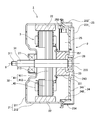
- Fig. 1 is a longitudinal cross-sectional view of a motor according to a first embodiment.
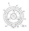
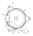
- Fig. 2 is a view of the inside of the motor according to the first embodiment, viewed from the front.
- Fig. 3 is a longitudinal cross-sectional view of a motor according to a second embodiment.
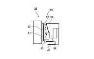
- Fig. 4 is a view of a back cover, a brush card, and a connector member according to the second embodiment, viewed from the front.
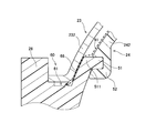
- Fig. 5 is a partial longitudinal cross-sectional view of the back cover, the brush card, and the connector member according to the second embodiment.
- Fig. 6 is a top view of the connector member according to the second embodiment.
- Fig. 7 is a view of the connector member according to the second embodiment, viewed from the front.
- Fig. 1 is a longitudinal cross-sectional view of a motor according to a first embodiment.
- Fig. 2 is a view of the inside of the motor according to the first embodiment, viewed from the front.
- Fig. 8 is a bottom view of the connector member according to the second embodiment.
- Fig. 9 is a view of the back cover according to the second embodiment, viewed from the front.
- Fig. 10 is a partial transverse cross-sectional view of a housing, the back cover, the brush card, and the connector member according to the second embodiment.
- Fig. 11 is a partial cross-sectional view of the housing, the back cover, and the brush card according to the second embodiment.
- Fig. 12 is a partial longitudinal cross-sectional view of the housing, the back cover, and the brush card according to the second embodiment.
- Fig. 13 is a partial longitudinal cross-sectional view of a housing, a back cover, and a brush card according to a modified embodiment.
- Fig. 14 is a partial longitudinal cross-sectional view of a housing, a back cover, and a brush card according to another modified embodiment.
- a direction parallel to the center axis of a motor is referred to as an "axial direction”
- a direction orthogonal to the center axis of the motor is referred to as a "radial direction”
- a direction along the arc about the center axis of the motor as the center is referred to as a "circumferential direction”.
- shapes and positional relationships of portions are described assuming that the axial direction is a forward and rearward direction and a housing side with respect to a back cover is a forward direction.
- a "parallel direction” in the present invention includes a substantially parallel direction.
- an “orthogonal direction” in the present invention includes a substantially orthogonal direction.
- Fig. 1 is a longitudinal cross-sectional view of a motor 1A according to a first embodiment.
- Fig. 2 is a view of the inside of the motor 1A viewed from the front.
- the motor 1A has a rotating portion 3A, a housing 21A, a back cover 23A, a brush card 24A, and a brush 25A.
- the rotating portion 3A is supported to be rotatable centered on a center axis 9A which substantially horizontally extends from the front to the rear.
- the rotating portion 3A has a commutator 33A.
- the housing 21A is a substantially cup-shaped member. At least a portion of the rotating portion 3A is accommodated in the housing 21A.
- the back cover 23A is a substantially cup-shaped member which is disposed rearward of the housing 21A.
- the commutator 33A, the brush card 24A and the brush 25A are disposed in a casing constituted by the housing 21A and the back cover 23A.
- the brush card 24A extends in a direction orthogonal to the central axis 9A. Further, the brush 25A is disposed forward of the brush card 24A, and is in contact with the commutator 33A.
- the back cover 23A includes a first rear wall portion 231A, a first circumferential wall portion 232A, and a through-hole 234A.
- the first rear wall portion 231A extends in the direction orthogonal to the central axis 9A in a rear side of the brush card 24A.
- the first circumferential wall portion 232A extends forward from an outer circumferential portion of the first rear wall portion 231A in a substantially cylindrical shape.
- the through-hole 234A penetrates up and down through the first circumferential wall portion 232A in the vicinity of a lower end portion of the first circumferential wall portion 232A.
- the back cover 23A and the brush card 24A are in contact with each other at a substantially annular contact portion 80A which is positioned radially inward of an inner circumferential surface of the first circumferential wall portion 232A. That is, the back cover 23A or the brush card 24A has the contact portion 80A of the substantially annular shape. A gap is provided between the inner circumferential surface of the first circumferential wall portion 232A and the contact portion 80A. Further, the contact portion 80A is disconnected at a position overlapped with the through-hole 234A in the radial direction.
- the motor 1 if liquid droplets infiltrate radially inward of the contact portion 80A, the droplets flow along an inner surface of the back cover 23A as indicated by the broken line arrow 901A in Fig. 1. And then, the droplets are discharged to the outside of the back cover 23A through the through-hole 234A. Further, if liquid droplets infiltrate between the first circumferential wall portion 232A and the contact portion 80A, the droplets flow along the inner surface of the back cover 23A as indicated by the broken line arrow 902A in Fig. 2. And then, the droplets are discharged to the outside the back cover 23A through the through-hole 234A. Accordingly, the motor 1 is capable of efficiently discharging the droplets from the inside of the back cover 23A. As a result, the motor 1 is capable of suppressing the droplets from adhering to the brush 25A.
- Fig. 3 is a longitudinal cross-sectional view of a motor 1 according to a second embodiment.
- the motor of this embodiment is mounted in, for example, a vehicle and is used as a driving source of an engine cooling fan.
- the motor 1 has a stationary portion 2 and a rotating portion 3.
- the stationary portion 2 is fixed to a frame body of an apparatus which is a driving object.
- the rotating portion 3 is supported to be rotatable with respect to the stationary portion 2.
- the stationary portion 2 of this embodiment includes a housing 21, a plurality of magnets 22, a back cover 23, a brush card 24, a plurality of brushes 25, a connector member 26, a front bearing portion 27, and a rear bearing portion 28.
- Fig. 4 is a view of the back cover 23, the brush card 24, and the connector member 26 viewed from the front. The following description will be provided appropriately with reference to Fig. 4 together with Fig. 3.
- the housing 21 is a substantially cup-shaped member which is opened rearward. At least a portion of the rotating portion 3 is accommodated in the housing 21.
- the housing 21 is formed of, for example, a metal such as a galvanized steel sheet. However, another material such as a resin may also be used as the material of the housing 21.
- the housing 21 includes a front wall portion 211 and a front circumferential wall portion 212.
- the front wall portion 211 extends in a substantially disk-like shape in a direction orthogonal to a central axis 9 in front of an armature 32 which will be described later.
- a front bearing holding portion 213 which holds the front bearing portion 27 is provided at the center of the front wall portion 211.
- the front circumferential wall portion 212 extends rearward from an outer circumferential portion of the front wall portion 211 in a substantially cylindrical shape.
- the plurality of magnets 22 are fixed to an inner circumferential surface of the front circumferential wall portion 212.
- the radially inner surfaces of the plurality of magnets 22 correspond to magnetic pole surfaces which radially oppose the armature 32 which will be described later.
- the plurality of magnets 22 are arranged at substantially uniform intervals in the circumferential direction so that the magnetic pole surface of N pole and the magnetic pole surface of S pole are alternately arranged.
- a single annular magnet in which the N poles and the S poles are alternately magnetized in the circumferential direction may be used instead of the plurality of magnets 22, a single annular magnet in which the N poles and the S poles are alternately magnetized in the circumferential direction may be used.
- the back cover 23 is a substantially cup-shaped member which is opened forward.
- the back cover 23 is disposed rearward of the housing 21.
- the back cover 23 is formed of, for example, a metal such as a galvanized steel sheet. However, another material such as a resin may also be used as the material of the back cover 23.
- the plurality of magnets 22, the brush card 24, the plurality of brushes 25, the armature 32 which will be described later, and the commutator 33 which will be described later are accommodated in a casing constituted by the housing 21 and the back cover 23.
- the back cover 23 includes a first rear wall portion 231 and a first circumferential wall portion 232.
- the first rear wall portion 231 extends, in the rear side of the brush card 24, in a substantially disk-like shape in a direction orthogonal to the central axis 9.
- a rear bearing holding portion 233 which holds the rear bearing portion 28 is provided at the center of the first rear wall portion 231.
- the first circumferential wall portion 232 extends forward from an outer circumferential portion of the first rear wall portion 231 in a substantially cylindrical shape.
- the first circumferential wall portion 232 includes a through-hole 234 and a cut-out 235.
- the through-hole 234 penetrates up and down through the first circumferential wall portion 232 in the vicinity of a lower end of the first circumferential wall portion 232.
- the cut-out 235 radially penetrates through the first circumferential wall portion 232 in the upper side of the through-hole 234.
- the cut-out 235 is disposed at a position having substantially the same height as that of the central axis 9, that is, at a position separated from the through-hole 234 by about 90 degrees with respect to the central axis 9.
- the brush card 24 is disposed forward of the first rear wall portion 231 and radially inward of the first circumferential wall portion 232.
- a resin which is an insulator is used as a material of the brush card 24.
- the brush card 24 includes a second rear wall portion 241 and a second circumferential wall portion 242.
- the second rear wall portion 241 extends, in the front side of the first rear wall portion 231, in a substantially disk-like shape in the direction orthogonal to the central axis 9.
- a circular hole 243 for disposing the rear bearing holding portion 233 or the commutator 33 which will be described later is provided at the center of the second rear wall portion 241.
- the second circumferential wall portion 242 extends forward from an outer circumferential portion of the second rear wall portion 241 in a substantially cylindrical shape.
- the plurality of brushes 25 are held by the brush card 24.
- Each brush 25 is a conductor which is in contact with the commutator 33 which will be described later.
- the plurality of brushes 25 are disposed forward of the second rear wall portion 241 and radially inward of the second circumferential wall portion 242. Accordingly, liquid droplets are suppressed from adhering to the brush 25.
- Each brush 25 includes a contact surface 251 which is in contact with a segment 331 of the commutator 33. Further, each brush 25 is biased radially inward by a spring 252 interposed between the brush 25 and the second circumferential wall portion 242. Accordingly, the contact surface 251 is pressed against the segment 331. As a result, the brush 25 and the segment 331 are electrically connected to each other.
- the connector member 26 is a member which supports lead wires that connect the brushes 25 to an external power source.
- a material of the connector member 26 for example, a resin that is an insulator is used.
- the connector member 26 is disposed in the radially outer side of the brush card 24. Further, the connector member 26 is fixed to the back cover 23 in the state of being fitted to the cut-out 235 of the back cover 23.
- the connector member 26 includes one or a plurality of communication holes 261.
- the communication hole 261 penetrates through the connector member 26 in the radial direction.
- the lead wire that extends from the external power source is connected to the brush 25 through the communication hole 251 of the connector member 26.
- the front bearing portion 27 and the rear bearing portion 28 are mechanisms that rotatably support a shaft 31 of the rotating portion 3.
- a ball bearing which rotates an outer race and an inner race relatively with respect to each other via a spherical body is used.
- the outer race of the front bearing portion 27 is fixed to the front bearing holding portion 213 of the housing 21.
- the outer race of the rear bearing portion 28 is fixed to the rear bearing holding portion 233 of the back cover 23.
- each inner race of the front bearing portion 27 and the rear bearing portion 28 is fixed to the shaft 31.
- the ball bearing instead of the ball bearing, other types of bearings such as a sliding bearing or a fluid bearing may be used.
- the rotating portion 3 of this embodiment includes the shaft 31, the armature 32, and the commutator 33.
- the shaft 31 is disposed along the central axis 9 that substantially horizontally extends in the front-rear direction.
- the shaft 31 is supported by the front bearing portion 27 and the rear bearing portion 28, and rotates centered on the central axis 9. Further, the shaft 31 includes a head portion 311 which protrudes more forward than the front wall portion 211 of the housing 21.
- a component which is a driving object, for example, an impeller is mounted to the head portion 311.
- the armature 32 is disposed radially inward of the plurality of magnets 22.
- the armature 32 includes an armature core 41 and a coil 42.
- the armature core 41 is formed of, for example, a laminated steel sheet.
- the armature core 41 includes a core back 411 of an annular shape, and a plurality of teeth 412 which protrude radially outward from the core back 411.
- the shaft 31 is press-fitted into the radial inside of the core back 411.
- the plurality of teeth 412 are arranged at uniform intervals in the circumferential direction.
- the coil 42 is constituted by a conducting wire wound on the teeth 412.
- the commutator 33 is fixed to the shaft 31 in the rear side of the armature 32.
- a plurality of conductive segments 331 are provided at uniform intervals in the circumferential direction on an outer circumferential surface of the commutator 33. Further, the conducting wire led out from the coil 42 is electrically connected to each segment 331.
- Driving current supplied from the external power source flows to the coil 42 through the lead wire, the brush 25 and the segment 331.
- a magnetic flux is generated in the teeth 412.
- a circumferential torque is generated by magnetic attraction or magnetic repulsion between the teeth 412 and the magnets 22.
- the rotating portion 3 rotates centered on the central axis 9 with respect to the stationary portion 2.
- the contact surfaces 251 of the respective brushes 25 sequentially come into contact with the plurality of segments 331.
- the driving current is sequentially supplied to the plurality of coils 42. Consequently, the rotating portion 3 continuously rotates.
- Fig. 5 is a partial longitudinal cross-sectional view of the back cover 23, the brush card 24 and the connector member 26.
- the connector member 26 includes a pair of protruding portions 51.
- the pair of protruding portions 51 protrude radially inward from both circumferential end portions of the connector member 26.
- the second circumferential wall portion 242 of the brush card 24 includes a pair of recessed portions 52.
- the pair of protruding portions 51 are fitted into the pair of recessed portions 52, respectively.
- Fig. 6 is a top view of the connector member 26.
- Fig. 7 is a view of the connector member 26, viewed from the front.
- Fig. 8 is a bottom view of the connector member 26.
- a flow path groove 60 is provided on the outer surface of the connector member 26. When liquid droplets such as water droplets adhere to the outer surface of the connector member 26, the liquid droplets are collected in the flow path groove 60 by gravity and surface tension.
- the flow path groove 60 includes an upper axial groove 61, a front circumferential groove 62, a lower axial groove 63, and a rear circumferential groove 64.
- the upper axial groove 61 axially extends on an upper surface of the connector member 26.
- the front circumferential groove 62 circumferentially and vertically extends on the surface of the front side of the connector member 26.
- the lower axial groove 63 axially extends on a lower surface of the connector member 26.
- the rear circumferential groove 64 circumferentially and vertically extends on the surface of the rear side of the connector member 26.
- Liquid droplets collected in the flow path groove 60 flow toward the lower axial groove 63 by gravity.
- the upper axial groove 61, the front circumferential groove 62, the lower axial groove 63, and the rear circumferential groove 64 are connected in an annular shape. Therefore, the liquid droplets collected in the upper axial groove 61 reach the lower axial groove 63 even when flowing to any of the front circumferential groove 62 and the rear circumferential groove 64. Accordingly, the liquid droplets are efficiently collected in the lower axial groove 63.
- a base end portion 511 of the protruding portion 51 of the connector member 26 is positioned in the radially outer side than the outer circumferential surface of the second circumferential wall portion 242 of the brush card 24. Accordingly, liquid droplets are suppressed from staying in the boundary between the second circumferential wall portion 242 and the protruding portion 51. Liquid droplets adhering to the outer circumferential surface of the second circumferential wall portion 242 flow toward the upper axial groove 61 along the base end portion 511 of the protruding portion 51 as indicated by the broken line arrow 91 in Fig. 5.
- the connector member 26 of this embodiment includes an inner dike surface 65 in the radially inner side of the flow path groove 60.
- the inner dike surface 65 extends radially inward from the edge of the radially inner side of the flow path groove 60. Further, the inner dike surface 65 is in contact with the housing 21 or the back cover 23. Accordingly, infiltration of liquid droplets into the radially inner side from the flow path groove 60 is suppressed.
- the connector member 26 of this embodiment includes a tapered surface 66 in the radially inner side of the upper axial groove 61.
- the tapered surface 66 is inclined so that the height thereof increases as it heads radially inward from the edge of the radially inner side of the upper axial groove 61. Therefore, even if liquid droplets collected in the upper axial groove 61 overflow from the upper axial groove 61, the liquid droplets return to the upper axial groove 61 due to tapered surface 66. Accordingly, infiltration of liquid droplets into the radially inner side is further suppressed.
- the tapered surface 66 is disposed radially inward than the first circumferential wall portion 232 of the back cover 23. Therefore, liquid droplets that flow toward the base end portion 511 of the protruding portion 51 from the outer circumferential surface of the second circumferential wall portion 242 are collected in the upper axial groove 61 through a space between the first circumferential wall portion 232 and the tapered surface 66 as indicated by the broken line arrow 91 in Fig. 5.
- the upper axial groove 61 in this embodiment includes a portion of which the width in the radial direction increases as it heads forward.
- the flow resistance of the portion increases as it heads toward the rear. Therefore, the liquid droplets collected in the upper axial groove 61 are guided forward as indicated by the broken line arrow 92 in Fig. 6. Further, liquid droplets that flow forward from the upper axial groove 61 flow to the lower axial groove 63 through the front circumferential groove 62.
- the connector member 26 of this embodiment includes a guide groove 67 in the radially inner side of the lower axial groove 63.
- the guide groove 67 extends radially inward from the lower axial groove 63.
- the lower axial groove 63 of this embodiment includes a portion of which the width in the radial direction increases as it heads toward the guide groove 67. The flow resistance of the portion decreases as it heads toward the guide groove 67. Therefore, the liquid droplets collected in the lower axial groove 63 are guided to the guide groove 67 side as indicated by the broken line arrow 93 in Fig. 8.
- Fig. 9 is a view of the back cover 23, when viewed from the front.
- the cut-out 235 of the back cover 23 includes an opposing surface 236 positioned in the lower side of the connector member 26.
- the opposing surface 236 vertically opposes the guide groove 67 of the connector member 26.
- the inner surface of the back cover 23 includes a flow path surface 70 which continues from the opposing surface 236 to the through-hole 234. Liquid droplets collected in the flow path groove 60 of the connector member 26 flow to the opposing surface 236 from the guide groove 67. Accordingly, the liquid droplets flow down the flow path surface 70 to the through-hole 234 as indicated by the broken line arrows 94 and 95 in Fig. 9 and are discharged to the outside of the back cover 23.
- liquid droplets adhering to the connector member 26 flow down the flow path groove 60 and the flow path surface 70 and are discharged to the outside of the back cover 23 through the through-hole 234. Therefore, in the motor 1, liquid droplets can be suppressed from adhering to the brush 25 without the need for an O-ring or a gasket as an essential component. As a result, the number of components of the motor 1 can be suppressed and the manufacturing cost can also be suppressed.
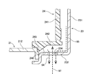
- Fig. 10 is a partial transverse cross-sectional view of the housing 21, the back cover 23, the brush card 24, and the connector member 26.
- the connector member 26 of this embodiment includes a plate-like protruding portion 262 in the radially inner side of the rear circumferential groove 64.
- the plate-like protruding portion 262 extends radially inward along the surface in the front side of the first rear wall portion 231.
- the surface in the rear side of the plate-like protruding portion 262 is in contact with the surface in the front side of the first rear wall portion 231.
- the end edge portion in the radially inner side of the plate-like protruding portion 262 is positioned in the radially inner side than the end edge portion in the radially outer side of the brush card 24.
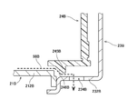
- Figs. 11 and 12 are partial cross-sectional views of the housing 21, the back cover 23, and the brush card 24.
- Fig. 12 illustrates a longitudinal cross-section including the through-hole 234.
- Fig. 11 illustrates a cross-section at a different position in the circumferential direction from that of Fig. 12.
- the first rear wall portion 231 of the back cover 23 includes an inner rear wall portion 81, an inner circumferential wall portion 82, and an outer rear wall portion 83.
- the inner rear wall portion 81 extends in the direction orthogonal to the center axis 9 in the rear side having a gap from the second rear wall portion 241 of the brush card.
- the inner circumferential wall portion 82 extends forward from the outer circumferential portion of the inner rear wall portion 81 in a substantially cylindrical shape.
- the outer rear wall portion 83 extends radially outward from the front end portion of the inner circumferential wall portion 82.
- the end edge portion in the radially outer side of the outer rear wall portion 83 is connected to the rear end portion of the first circumferential wall portion 232.
- the brush card 24 includes a leg portion 244 of substantially annular shape.
- the leg portion 244 extends rearward from the outer circumferential portion of the second rear wall portion 241.
- the outer rear wall portion 83 of the back cover 23 and the leg portion 244 of the brush card 24 are in contact with each other at a substantially annular contact portion 80. That is, the back cover 23 or the brush card 24 has the substantially annular contact portion 80.
- the contact portion 80 is positioned in the radially inner side having a gap from the inner circumferential surface of the first circumferential wall portion 232.
- the flow path surface 70 of the back cover 23 includes a first flow path surface 71 and a second flow path surface 72.
- the first flow path surface 71 is positioned in the radially outer side than the contact portion 80. Further, the first flow path surface 71 belongs to the inner circumferential surface of the first circumferential wall portion 232 and the surface in the front side of the outer rear wall portion 83.
- the second flow path surface 72 is positioned radially inward than the contact portion 80.
- the second flow path surface 72 belongs to the surface on the front side of the inner rear wall portion 81 and the inner circumferential surface of the inner circumferential wall portion 82.
- Liquid droplets infiltrated between the first circumferential wall portion 232 and the contact portion 80 flow down the first flow path surface 71 to the through-hole 234 as indicated by the broken line arrow 94 in Figs. 9 and 12. Further, liquid droplets infiltrated into the radially inner side than the contact portion 80 flow down the second flow path surface 72 to the through-hole 234 as indicated by the broken line arrow 95 in Figs. 9 and 12. In this way, the motor 1 of this embodiment may discharge liquid droplets infiltrated into the back cover 23 through two paths.
- liquid droplets that are present in any of the radially outer side and the radially inner side of the contact portion 80 can also be discharged to the outside of the back cover 23 through the through-hole 234. Therefore, in the motor 1, the liquid droplets can be efficiently discharged from the inside of the back cover 23. As a result, in the motor 1, the liquid droplets can be suppressed from adhering to the brush 25.
- the inner circumferential wall portion 82 and the outer rear wall portion 83 are not provided at a position that overlaps with the through-hole 234 in the radial direction. Therefore, as shown in Fig. 12, the contact portion 80 is disconnected at the position that overlaps with the through-hole 234 in the radial direction. Therefore, in the motor 1, liquid droplets that flow down the second flow path surface 72 can flow to the through-hole 234 through the portion where the contact portion 80 is disconnected.
- the surface in the front side of the inner rear wall portion 81 is a flat surface without stepped portions. Therefore, in the motor 1, liquid droplets can more efficiently flow along the second flow path surface 72 to the through-hole 234.
- Liquid droplets discharged from the through-hole 234 are not only the liquid droplets that are guided to the back cover 23 through the flow path groove 60 of the connector member 26.
- liquid droplets infiltrated through a through-hole provided in the housing 21 or liquid droplets infiltrated from the boundary portion between the housing 21 and the back cover 23 also flow down the first flow path surface 71 and the second flow path surface 72 and are discharged to the outside of the back cover 23 through the through-hole 234.
- the inner circumferential surface of the first circumferential wall portion 232 of the back cover 23 and the outer circumferential surface of the second circumferential wall portion 242 of the brush card 24 oppose each other via a gap in the radial direction. Accordingly, movement of liquid droplets from the first flow path surface 71 toward the brush 25 is further suppressed.
- the surface in the front side of the first rear wall portion 231 of the back cover 23 and the surface in the rear side of the second rear wall portion 241 of the brush card 24 oppose each other via a gap in the axial direction. Accordingly, movement of liquid droplets from the second flow path surface 72 to the brush 25 is further suppressed.
- the gap in the axial direction is formed by allowing the outer rear wall portion 83 of the back cover 23 and the leg portion 244 of the brush card 24 to come into contact with each other.
- one of the outer rear wall portion 83 and the leg portion 244 may also be omitted.
- the motor 1 of this embodiment brings cooling air into the housing 21 and the back cover 23 when driving. Specifically, as indicated by the broken line arrow 97 in Fig. 12, gas flows into the back cover 23 through the through-hole 234. The air current occurs due to the rotation of the rotating portion 3. The brush 25 and the coil 42 are cooled by the gas.
- the front end portion of the second circumferential wall portion 242 of the brush card 24 is positioned forward than the through-hole 234. Therefore, the gas indicated by the arrow 97 is suppressed from being directly blown to the radial inside of the second circumferential wall portion 242. Therefore, even though liquid droplets are mixed with the gas indicated by the arrow 97, infiltration of the liquid droplets to the radially inner side than the second circumferential wall portion 242 is suppressed.
- the brush card 24 of this embodiment has an overhang portion 245.
- the overhang portion 245 protrudes radially outward from the outer circumferential surface of the second circumferential wall portion 242.
- the overhang portion 245 is positioned forward than the rear end portion of the through-hole 234. Accordingly, inflow of the gas indicated by the arrow 97 toward the front is further suppressed.
- the radially outer surface of the overhang portion 245 is an inclined surface 246 which is displaced forward as it heads radially outward.
- the surface in the front side of the overhang portion 245 comes into contact with the rear end portion of the housing 21. Accordingly, inflow of the gas toward the front is further suppressed.
- Fig. 13 is a partial longitudinal cross-sectional view of a housing 21B, a back cover 23B, and a brush card 24B according to a modified embodiment.
- a gap in the radial direction is interposed between an overhang portion 245B and the inner circumferential surface of a first circumferential wall portion 232B or the inner circumferential surface of a front circumferential wall portion 212B. In this manner, as indicated by the arrow 98 in Fig.
- liquid droplets infiltrated into the housing 21B can flow down the inner circumferential surface of the front circumferential wall portion 212B and the inner circumferential wall surface of the first circumferential wall portion 232B and can be discharged to the outside of the back cover 23B through a through-hole 234.
- the surface in the front side of the overhang portion 245B is an inclined surface 246B which is displaced rearward as it heads radially outwards. Therefore, in the structure of the embodiment of Fig. 13, in the radially outer side of the overhang portion 245B, liquid droplets can be guided toward the through-hole 234B more efficiently.
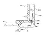
- Fig. 14 is a partial longitudinal cross-sectional view of a housing 21C, a back cover 23C, and a brush card 24C according to another modified embodiment.
- a contact portion 80C between the back cover 23C and the brush card 24C is not disconnected at a position that overlaps with a through-hole 234C in the radial direction. That is, even at the position that overlaps with the through-hole 234C in the radial direction, a first rear wall portion 231C of the back cover 23C and a leg portion 244C of the brush card 24C are in contact with each other.
- the leg portion 244C of the brush card 24C has a flow path hole 247C that penetrates from the radially inner side than the contact portion 80C to the radially outer side. Therefore, liquid droplets that flow down a second flow path surface 72C can flow toward the through-hole 234 through the flow path hole 247C.
- the leg portion 244C may also be provided with a cut-out instead of the flow path hole 247C
- the motor of the present invention may be a motor for rotating an in-vehicle fan or may also be a motor used for other purposes.
- the motor of the present invention may also be used as a driving source of power steering of a vehicle.
- the motor may also be mounted in home appliances, office automation equipment, medical equipment, and the like to generate various types of driving forces.
- the present invention is particularly useful to a motor used in an environment in which liquid droplets are likely to be present. Therefore, the present invention is particularly useful to a motor mounted in a transportation machine such as a car, or a fan motor for cooling a server provided outdoors, a router, a communication base, a switch device, or the like.
- the number of through-holes provided in the back cover may be one as in the above-described embodiments or may also be two or more.
- the position of the connector member may not necessarily be the position that is separated from the through-hole by about 90 degrees with respect to the center axis 9.
- detailed shapes of the members may also be different from the shapes illustrated in the drawings of the present invention.
- the drainage structure of the present invention may also be used in combination with a seal member such as an O-ring or a gasket.
- the invention may be applied to a motor.
Landscapes
- Engineering & Computer Science (AREA)
- Power Engineering (AREA)
- Motor Or Generator Frames (AREA)
- Motor Or Generator Current Collectors (AREA)
Priority Applications (4)
| Application Number | Priority Date | Filing Date | Title |
|---|---|---|---|
| DE112013002640.6T DE112013002640T5 (de) | 2012-05-22 | 2013-05-17 | Motor |
| IN2298MUN2014 IN2014MN02298A (enExample) | 2012-05-22 | 2013-05-17 | |
| CN201380027005.7A CN104541439B (zh) | 2012-05-22 | 2013-05-17 | 马达 |
| US14/399,257 US20150130310A1 (en) | 2012-05-22 | 2013-05-17 | Motor |
Applications Claiming Priority (2)
| Application Number | Priority Date | Filing Date | Title |
|---|---|---|---|
| JP2012116844A JP5843163B2 (ja) | 2012-05-22 | 2012-05-22 | モータ |
| JP2012-116844 | 2012-05-22 |
Publications (1)
| Publication Number | Publication Date |
|---|---|
| WO2013175750A1 true WO2013175750A1 (en) | 2013-11-28 |
Family
ID=49623460
Family Applications (1)
| Application Number | Title | Priority Date | Filing Date |
|---|---|---|---|
| PCT/JP2013/003162 Ceased WO2013175750A1 (en) | 2012-05-22 | 2013-05-17 | Motor |
Country Status (6)
| Country | Link |
|---|---|
| US (1) | US20150130310A1 (enExample) |
| JP (1) | JP5843163B2 (enExample) |
| CN (1) | CN104541439B (enExample) |
| DE (1) | DE112013002640T5 (enExample) |
| IN (1) | IN2014MN02298A (enExample) |
| WO (1) | WO2013175750A1 (enExample) |
Families Citing this family (6)
| Publication number | Priority date | Publication date | Assignee | Title |
|---|---|---|---|---|
| CN110268605A (zh) * | 2017-02-20 | 2019-09-20 | 日本电产株式会社 | 马达 |
| WO2019065237A1 (ja) * | 2017-09-29 | 2019-04-04 | 日本電産株式会社 | モータ |
| US10641286B2 (en) * | 2017-11-07 | 2020-05-05 | Air Cool Industrial Co., Ltd. | Waterproof structure of wall-mounted fan housing |
| CN111384810B (zh) * | 2018-12-28 | 2022-11-11 | 日本电产(大连)有限公司 | 有刷马达以及电气设备 |
| WO2020194959A1 (ja) * | 2019-03-28 | 2020-10-01 | アイシン・エィ・ダブリュ株式会社 | 回転電機 |
| JP6858832B1 (ja) * | 2019-12-02 | 2021-04-14 | 三菱電機株式会社 | 制御装置一体型回転電機 |
Citations (4)
| Publication number | Priority date | Publication date | Assignee | Title |
|---|---|---|---|---|
| JPH0723961U (ja) * | 1993-10-01 | 1995-05-02 | 国産電機株式会社 | 直流電動機 |
| JPH11168849A (ja) * | 1997-12-01 | 1999-06-22 | Jeco Co Ltd | モータの防水構造 |
| JP2006174589A (ja) * | 2004-12-15 | 2006-06-29 | Denso Corp | 回転電機 |
| JP3971349B2 (ja) * | 2003-06-27 | 2007-09-05 | アスモ株式会社 | 車両空調用モータの防水構造 |
Family Cites Families (10)
| Publication number | Priority date | Publication date | Assignee | Title |
|---|---|---|---|---|
| JPH0628935Y2 (ja) * | 1988-09-30 | 1994-08-03 | 三ツ葉電機製作所 | ヨークのドレンカバー装置 |
| GB2239563B (en) * | 1989-12-06 | 1994-03-23 | Mitsuba Electric Mfg Co | Drain device of revolving electric machine |
| JP2000333411A (ja) * | 1999-05-21 | 2000-11-30 | Mitsuba Corp | ファンモータの冷却構造 |
| FR2856852B1 (fr) * | 2003-06-27 | 2006-09-29 | Asmo Co Ltd | Ensemble moteur pour climatiseur pour vehicules |
| JP4337669B2 (ja) * | 2004-07-13 | 2009-09-30 | 株式会社デンソー | 車両用電動送風ファン装置 |
| KR100790899B1 (ko) * | 2006-12-01 | 2008-01-03 | 삼성전자주식회사 | 얼라인 마크가 형성된 템플릿 및 그 제조 방법 |
| DE102007056323A1 (de) * | 2007-11-22 | 2009-05-28 | Robert Bosch Gmbh | Gleichstrommaschine |
| CN201263030Y (zh) * | 2008-08-28 | 2009-06-24 | 成都华川电装有限责任公司 | 汽车起动电机 |
| CN101741181B (zh) * | 2008-11-26 | 2013-06-12 | 德昌电机(深圳)有限公司 | 用于暖通空调领域的电机 |
| CN201830091U (zh) * | 2010-10-29 | 2011-05-11 | 无锡哈电电机有限公司 | 滑环通风冷却系统结构 |
-
2012
- 2012-05-22 JP JP2012116844A patent/JP5843163B2/ja not_active Expired - Fee Related
-
2013
- 2013-05-17 CN CN201380027005.7A patent/CN104541439B/zh not_active Expired - Fee Related
- 2013-05-17 US US14/399,257 patent/US20150130310A1/en not_active Abandoned
- 2013-05-17 DE DE112013002640.6T patent/DE112013002640T5/de not_active Withdrawn
- 2013-05-17 IN IN2298MUN2014 patent/IN2014MN02298A/en unknown
- 2013-05-17 WO PCT/JP2013/003162 patent/WO2013175750A1/en not_active Ceased
Patent Citations (4)
| Publication number | Priority date | Publication date | Assignee | Title |
|---|---|---|---|---|
| JPH0723961U (ja) * | 1993-10-01 | 1995-05-02 | 国産電機株式会社 | 直流電動機 |
| JPH11168849A (ja) * | 1997-12-01 | 1999-06-22 | Jeco Co Ltd | モータの防水構造 |
| JP3971349B2 (ja) * | 2003-06-27 | 2007-09-05 | アスモ株式会社 | 車両空調用モータの防水構造 |
| JP2006174589A (ja) * | 2004-12-15 | 2006-06-29 | Denso Corp | 回転電機 |
Also Published As
| Publication number | Publication date |
|---|---|
| JP2013243892A (ja) | 2013-12-05 |
| US20150130310A1 (en) | 2015-05-14 |
| IN2014MN02298A (enExample) | 2015-08-07 |
| CN104541439A (zh) | 2015-04-22 |
| CN104541439B (zh) | 2017-05-17 |
| JP5843163B2 (ja) | 2016-01-13 |
| DE112013002640T5 (de) | 2015-03-19 |
Similar Documents
| Publication | Publication Date | Title |
|---|---|---|
| US9960652B2 (en) | Motor | |
| WO2013175750A1 (en) | Motor | |
| US9893588B2 (en) | Motor housing with cooling channel and resin injected winding ends for improved heat transfer | |
| US10084361B2 (en) | Motor | |
| US9653960B2 (en) | Motor and blower | |
| JP4483948B2 (ja) | 回転電機 | |
| US9496762B2 (en) | Motor | |
| US9876409B2 (en) | Inner-rotor motor with upper and lower brackets press-fit with the stator core, and a circuit board | |
| WO2017098907A1 (ja) | モータ | |
| JP2013042633A (ja) | モータ | |
| US20190234406A1 (en) | Pump device | |
| US11056953B2 (en) | Stator unit, motor, and fan motor | |
| JP7658072B2 (ja) | モータユニット | |
| JP2017184525A (ja) | ステータユニット、モータ、および並列ファン | |
| JP2021052492A (ja) | バスバーユニットおよびモータ | |
| JP2021058000A (ja) | モータおよびトランスミッション装置 | |
| US9379593B2 (en) | Vehicle drive device | |
| CN110771007A (zh) | 定子和马达 | |
| US20190285116A1 (en) | Motor and fan motor | |
| KR100660305B1 (ko) | 브러시리스 직류모터 | |
| JP2016226231A (ja) | 回転電機 | |
| CN113472132B (zh) | 马达 | |
| CN111066229A (zh) | 马达 | |
| CN111749985B (zh) | 气体动压轴承、马达以及风扇马达 | |
| JP2009153360A (ja) | モーターコイル |
Legal Events
| Date | Code | Title | Description |
|---|---|---|---|
| 121 | Ep: the epo has been informed by wipo that ep was designated in this application |
Ref document number: 13794556 Country of ref document: EP Kind code of ref document: A1 |
|
| WWE | Wipo information: entry into national phase |
Ref document number: 14399257 Country of ref document: US |
|
| WWE | Wipo information: entry into national phase |
Ref document number: 1120130026406 Country of ref document: DE Ref document number: 112013002640 Country of ref document: DE |
|
| 122 | Ep: pct application non-entry in european phase |
Ref document number: 13794556 Country of ref document: EP Kind code of ref document: A1 |