WO2013171797A1 - 車両 - Google Patents
車両 Download PDFInfo
- Publication number
- WO2013171797A1 WO2013171797A1 PCT/JP2012/003245 JP2012003245W WO2013171797A1 WO 2013171797 A1 WO2013171797 A1 WO 2013171797A1 JP 2012003245 W JP2012003245 W JP 2012003245W WO 2013171797 A1 WO2013171797 A1 WO 2013171797A1
- Authority
- WO
- WIPO (PCT)
- Prior art keywords
- blower
- power storage
- duct
- blower motor
- storage unit
- Prior art date
Links
Images


Classifications
-
- B—PERFORMING OPERATIONS; TRANSPORTING
- B60—VEHICLES IN GENERAL
- B60K—ARRANGEMENT OR MOUNTING OF PROPULSION UNITS OR OF TRANSMISSIONS IN VEHICLES; ARRANGEMENT OR MOUNTING OF PLURAL DIVERSE PRIME-MOVERS IN VEHICLES; AUXILIARY DRIVES FOR VEHICLES; INSTRUMENTATION OR DASHBOARDS FOR VEHICLES; ARRANGEMENTS IN CONNECTION WITH COOLING, AIR INTAKE, GAS EXHAUST OR FUEL SUPPLY OF PROPULSION UNITS IN VEHICLES
- B60K11/00—Arrangement in connection with cooling of propulsion units
- B60K11/06—Arrangement in connection with cooling of propulsion units with air cooling
-
- B—PERFORMING OPERATIONS; TRANSPORTING
- B60—VEHICLES IN GENERAL
- B60K—ARRANGEMENT OR MOUNTING OF PROPULSION UNITS OR OF TRANSMISSIONS IN VEHICLES; ARRANGEMENT OR MOUNTING OF PLURAL DIVERSE PRIME-MOVERS IN VEHICLES; AUXILIARY DRIVES FOR VEHICLES; INSTRUMENTATION OR DASHBOARDS FOR VEHICLES; ARRANGEMENTS IN CONNECTION WITH COOLING, AIR INTAKE, GAS EXHAUST OR FUEL SUPPLY OF PROPULSION UNITS IN VEHICLES
- B60K1/00—Arrangement or mounting of electrical propulsion units
- B60K1/04—Arrangement or mounting of electrical propulsion units of the electric storage means for propulsion
-
- B—PERFORMING OPERATIONS; TRANSPORTING
- B60—VEHICLES IN GENERAL
- B60L—PROPULSION OF ELECTRICALLY-PROPELLED VEHICLES; SUPPLYING ELECTRIC POWER FOR AUXILIARY EQUIPMENT OF ELECTRICALLY-PROPELLED VEHICLES; ELECTRODYNAMIC BRAKE SYSTEMS FOR VEHICLES IN GENERAL; MAGNETIC SUSPENSION OR LEVITATION FOR VEHICLES; MONITORING OPERATING VARIABLES OF ELECTRICALLY-PROPELLED VEHICLES; ELECTRIC SAFETY DEVICES FOR ELECTRICALLY-PROPELLED VEHICLES
- B60L1/00—Supplying electric power to auxiliary equipment of vehicles
- B60L1/003—Supplying electric power to auxiliary equipment of vehicles to auxiliary motors, e.g. for pumps, compressors
-
- B—PERFORMING OPERATIONS; TRANSPORTING
- B60—VEHICLES IN GENERAL
- B60L—PROPULSION OF ELECTRICALLY-PROPELLED VEHICLES; SUPPLYING ELECTRIC POWER FOR AUXILIARY EQUIPMENT OF ELECTRICALLY-PROPELLED VEHICLES; ELECTRODYNAMIC BRAKE SYSTEMS FOR VEHICLES IN GENERAL; MAGNETIC SUSPENSION OR LEVITATION FOR VEHICLES; MONITORING OPERATING VARIABLES OF ELECTRICALLY-PROPELLED VEHICLES; ELECTRIC SAFETY DEVICES FOR ELECTRICALLY-PROPELLED VEHICLES
- B60L3/00—Electric devices on electrically-propelled vehicles for safety purposes; Monitoring operating variables, e.g. speed, deceleration or energy consumption
- B60L3/0007—Measures or means for preventing or attenuating collisions
-
- B—PERFORMING OPERATIONS; TRANSPORTING
- B60—VEHICLES IN GENERAL
- B60L—PROPULSION OF ELECTRICALLY-PROPELLED VEHICLES; SUPPLYING ELECTRIC POWER FOR AUXILIARY EQUIPMENT OF ELECTRICALLY-PROPELLED VEHICLES; ELECTRODYNAMIC BRAKE SYSTEMS FOR VEHICLES IN GENERAL; MAGNETIC SUSPENSION OR LEVITATION FOR VEHICLES; MONITORING OPERATING VARIABLES OF ELECTRICALLY-PROPELLED VEHICLES; ELECTRIC SAFETY DEVICES FOR ELECTRICALLY-PROPELLED VEHICLES
- B60L50/00—Electric propulsion with power supplied within the vehicle
- B60L50/50—Electric propulsion with power supplied within the vehicle using propulsion power supplied by batteries or fuel cells
- B60L50/51—Electric propulsion with power supplied within the vehicle using propulsion power supplied by batteries or fuel cells characterised by AC-motors
-
- B—PERFORMING OPERATIONS; TRANSPORTING
- B60—VEHICLES IN GENERAL
- B60L—PROPULSION OF ELECTRICALLY-PROPELLED VEHICLES; SUPPLYING ELECTRIC POWER FOR AUXILIARY EQUIPMENT OF ELECTRICALLY-PROPELLED VEHICLES; ELECTRODYNAMIC BRAKE SYSTEMS FOR VEHICLES IN GENERAL; MAGNETIC SUSPENSION OR LEVITATION FOR VEHICLES; MONITORING OPERATING VARIABLES OF ELECTRICALLY-PROPELLED VEHICLES; ELECTRIC SAFETY DEVICES FOR ELECTRICALLY-PROPELLED VEHICLES
- B60L50/00—Electric propulsion with power supplied within the vehicle
- B60L50/50—Electric propulsion with power supplied within the vehicle using propulsion power supplied by batteries or fuel cells
- B60L50/60—Electric propulsion with power supplied within the vehicle using propulsion power supplied by batteries or fuel cells using power supplied by batteries
- B60L50/64—Constructional details of batteries specially adapted for electric vehicles
-
- B—PERFORMING OPERATIONS; TRANSPORTING
- B60—VEHICLES IN GENERAL
- B60L—PROPULSION OF ELECTRICALLY-PROPELLED VEHICLES; SUPPLYING ELECTRIC POWER FOR AUXILIARY EQUIPMENT OF ELECTRICALLY-PROPELLED VEHICLES; ELECTRODYNAMIC BRAKE SYSTEMS FOR VEHICLES IN GENERAL; MAGNETIC SUSPENSION OR LEVITATION FOR VEHICLES; MONITORING OPERATING VARIABLES OF ELECTRICALLY-PROPELLED VEHICLES; ELECTRIC SAFETY DEVICES FOR ELECTRICALLY-PROPELLED VEHICLES
- B60L50/00—Electric propulsion with power supplied within the vehicle
- B60L50/50—Electric propulsion with power supplied within the vehicle using propulsion power supplied by batteries or fuel cells
- B60L50/60—Electric propulsion with power supplied within the vehicle using propulsion power supplied by batteries or fuel cells using power supplied by batteries
- B60L50/66—Arrangements of batteries
-
- B—PERFORMING OPERATIONS; TRANSPORTING
- B60—VEHICLES IN GENERAL
- B60L—PROPULSION OF ELECTRICALLY-PROPELLED VEHICLES; SUPPLYING ELECTRIC POWER FOR AUXILIARY EQUIPMENT OF ELECTRICALLY-PROPELLED VEHICLES; ELECTRODYNAMIC BRAKE SYSTEMS FOR VEHICLES IN GENERAL; MAGNETIC SUSPENSION OR LEVITATION FOR VEHICLES; MONITORING OPERATING VARIABLES OF ELECTRICALLY-PROPELLED VEHICLES; ELECTRIC SAFETY DEVICES FOR ELECTRICALLY-PROPELLED VEHICLES
- B60L58/00—Methods or circuit arrangements for monitoring or controlling batteries or fuel cells, specially adapted for electric vehicles
- B60L58/10—Methods or circuit arrangements for monitoring or controlling batteries or fuel cells, specially adapted for electric vehicles for monitoring or controlling batteries
- B60L58/18—Methods or circuit arrangements for monitoring or controlling batteries or fuel cells, specially adapted for electric vehicles for monitoring or controlling batteries of two or more battery modules
- B60L58/21—Methods or circuit arrangements for monitoring or controlling batteries or fuel cells, specially adapted for electric vehicles for monitoring or controlling batteries of two or more battery modules having the same nominal voltage
-
- B—PERFORMING OPERATIONS; TRANSPORTING
- B60—VEHICLES IN GENERAL
- B60L—PROPULSION OF ELECTRICALLY-PROPELLED VEHICLES; SUPPLYING ELECTRIC POWER FOR AUXILIARY EQUIPMENT OF ELECTRICALLY-PROPELLED VEHICLES; ELECTRODYNAMIC BRAKE SYSTEMS FOR VEHICLES IN GENERAL; MAGNETIC SUSPENSION OR LEVITATION FOR VEHICLES; MONITORING OPERATING VARIABLES OF ELECTRICALLY-PROPELLED VEHICLES; ELECTRIC SAFETY DEVICES FOR ELECTRICALLY-PROPELLED VEHICLES
- B60L58/00—Methods or circuit arrangements for monitoring or controlling batteries or fuel cells, specially adapted for electric vehicles
- B60L58/10—Methods or circuit arrangements for monitoring or controlling batteries or fuel cells, specially adapted for electric vehicles for monitoring or controlling batteries
- B60L58/24—Methods or circuit arrangements for monitoring or controlling batteries or fuel cells, specially adapted for electric vehicles for monitoring or controlling batteries for controlling the temperature of batteries
- B60L58/26—Methods or circuit arrangements for monitoring or controlling batteries or fuel cells, specially adapted for electric vehicles for monitoring or controlling batteries for controlling the temperature of batteries by cooling
-
- H—ELECTRICITY
- H01—ELECTRIC ELEMENTS
- H01M—PROCESSES OR MEANS, e.g. BATTERIES, FOR THE DIRECT CONVERSION OF CHEMICAL ENERGY INTO ELECTRICAL ENERGY
- H01M10/00—Secondary cells; Manufacture thereof
- H01M10/60—Heating or cooling; Temperature control
- H01M10/61—Types of temperature control
- H01M10/613—Cooling or keeping cold
-
- H—ELECTRICITY
- H01—ELECTRIC ELEMENTS
- H01M—PROCESSES OR MEANS, e.g. BATTERIES, FOR THE DIRECT CONVERSION OF CHEMICAL ENERGY INTO ELECTRICAL ENERGY
- H01M10/00—Secondary cells; Manufacture thereof
- H01M10/60—Heating or cooling; Temperature control
- H01M10/62—Heating or cooling; Temperature control specially adapted for specific applications
- H01M10/625—Vehicles
-
- H—ELECTRICITY
- H01—ELECTRIC ELEMENTS
- H01M—PROCESSES OR MEANS, e.g. BATTERIES, FOR THE DIRECT CONVERSION OF CHEMICAL ENERGY INTO ELECTRICAL ENERGY
- H01M10/00—Secondary cells; Manufacture thereof
- H01M10/60—Heating or cooling; Temperature control
- H01M10/65—Means for temperature control structurally associated with the cells
- H01M10/656—Means for temperature control structurally associated with the cells characterised by the type of heat-exchange fluid
- H01M10/6561—Gases
- H01M10/6563—Gases with forced flow, e.g. by blowers
-
- H—ELECTRICITY
- H01—ELECTRIC ELEMENTS
- H01M—PROCESSES OR MEANS, e.g. BATTERIES, FOR THE DIRECT CONVERSION OF CHEMICAL ENERGY INTO ELECTRICAL ENERGY
- H01M10/00—Secondary cells; Manufacture thereof
- H01M10/60—Heating or cooling; Temperature control
- H01M10/66—Heat-exchange relationships between the cells and other systems, e.g. central heating systems or fuel cells
-
- H—ELECTRICITY
- H01—ELECTRIC ELEMENTS
- H01M—PROCESSES OR MEANS, e.g. BATTERIES, FOR THE DIRECT CONVERSION OF CHEMICAL ENERGY INTO ELECTRICAL ENERGY
- H01M50/00—Constructional details or processes of manufacture of the non-active parts of electrochemical cells other than fuel cells, e.g. hybrid cells
- H01M50/20—Mountings; Secondary casings or frames; Racks, modules or packs; Suspension devices; Shock absorbers; Transport or carrying devices; Holders
- H01M50/204—Racks, modules or packs for multiple batteries or multiple cells
-
- H—ELECTRICITY
- H01—ELECTRIC ELEMENTS
- H01M—PROCESSES OR MEANS, e.g. BATTERIES, FOR THE DIRECT CONVERSION OF CHEMICAL ENERGY INTO ELECTRICAL ENERGY
- H01M50/00—Constructional details or processes of manufacture of the non-active parts of electrochemical cells other than fuel cells, e.g. hybrid cells
- H01M50/20—Mountings; Secondary casings or frames; Racks, modules or packs; Suspension devices; Shock absorbers; Transport or carrying devices; Holders
- H01M50/233—Mountings; Secondary casings or frames; Racks, modules or packs; Suspension devices; Shock absorbers; Transport or carrying devices; Holders characterised by physical properties of casings or racks, e.g. dimensions
- H01M50/24—Mountings; Secondary casings or frames; Racks, modules or packs; Suspension devices; Shock absorbers; Transport or carrying devices; Holders characterised by physical properties of casings or racks, e.g. dimensions adapted for protecting batteries from their environment, e.g. from corrosion
-
- H—ELECTRICITY
- H01—ELECTRIC ELEMENTS
- H01M—PROCESSES OR MEANS, e.g. BATTERIES, FOR THE DIRECT CONVERSION OF CHEMICAL ENERGY INTO ELECTRICAL ENERGY
- H01M50/00—Constructional details or processes of manufacture of the non-active parts of electrochemical cells other than fuel cells, e.g. hybrid cells
- H01M50/20—Mountings; Secondary casings or frames; Racks, modules or packs; Suspension devices; Shock absorbers; Transport or carrying devices; Holders
- H01M50/249—Mountings; Secondary casings or frames; Racks, modules or packs; Suspension devices; Shock absorbers; Transport or carrying devices; Holders specially adapted for aircraft or vehicles, e.g. cars or trains
-
- B—PERFORMING OPERATIONS; TRANSPORTING
- B60—VEHICLES IN GENERAL
- B60K—ARRANGEMENT OR MOUNTING OF PROPULSION UNITS OR OF TRANSMISSIONS IN VEHICLES; ARRANGEMENT OR MOUNTING OF PLURAL DIVERSE PRIME-MOVERS IN VEHICLES; AUXILIARY DRIVES FOR VEHICLES; INSTRUMENTATION OR DASHBOARDS FOR VEHICLES; ARRANGEMENTS IN CONNECTION WITH COOLING, AIR INTAKE, GAS EXHAUST OR FUEL SUPPLY OF PROPULSION UNITS IN VEHICLES
- B60K1/00—Arrangement or mounting of electrical propulsion units
- B60K2001/003—Arrangement or mounting of electrical propulsion units with means for cooling the electrical propulsion units
- B60K2001/005—Arrangement or mounting of electrical propulsion units with means for cooling the electrical propulsion units the electric storage means
-
- B—PERFORMING OPERATIONS; TRANSPORTING
- B60—VEHICLES IN GENERAL
- B60K—ARRANGEMENT OR MOUNTING OF PROPULSION UNITS OR OF TRANSMISSIONS IN VEHICLES; ARRANGEMENT OR MOUNTING OF PLURAL DIVERSE PRIME-MOVERS IN VEHICLES; AUXILIARY DRIVES FOR VEHICLES; INSTRUMENTATION OR DASHBOARDS FOR VEHICLES; ARRANGEMENTS IN CONNECTION WITH COOLING, AIR INTAKE, GAS EXHAUST OR FUEL SUPPLY OF PROPULSION UNITS IN VEHICLES
- B60K1/00—Arrangement or mounting of electrical propulsion units
- B60K1/04—Arrangement or mounting of electrical propulsion units of the electric storage means for propulsion
- B60K2001/0405—Arrangement or mounting of electrical propulsion units of the electric storage means for propulsion characterised by their position
- B60K2001/0433—Arrangement under the rear seats
-
- B—PERFORMING OPERATIONS; TRANSPORTING
- B60—VEHICLES IN GENERAL
- B60L—PROPULSION OF ELECTRICALLY-PROPELLED VEHICLES; SUPPLYING ELECTRIC POWER FOR AUXILIARY EQUIPMENT OF ELECTRICALLY-PROPELLED VEHICLES; ELECTRODYNAMIC BRAKE SYSTEMS FOR VEHICLES IN GENERAL; MAGNETIC SUSPENSION OR LEVITATION FOR VEHICLES; MONITORING OPERATING VARIABLES OF ELECTRICALLY-PROPELLED VEHICLES; ELECTRIC SAFETY DEVICES FOR ELECTRICALLY-PROPELLED VEHICLES
- B60L2210/00—Converter types
- B60L2210/10—DC to DC converters
-
- B—PERFORMING OPERATIONS; TRANSPORTING
- B60—VEHICLES IN GENERAL
- B60L—PROPULSION OF ELECTRICALLY-PROPELLED VEHICLES; SUPPLYING ELECTRIC POWER FOR AUXILIARY EQUIPMENT OF ELECTRICALLY-PROPELLED VEHICLES; ELECTRODYNAMIC BRAKE SYSTEMS FOR VEHICLES IN GENERAL; MAGNETIC SUSPENSION OR LEVITATION FOR VEHICLES; MONITORING OPERATING VARIABLES OF ELECTRICALLY-PROPELLED VEHICLES; ELECTRIC SAFETY DEVICES FOR ELECTRICALLY-PROPELLED VEHICLES
- B60L2240/00—Control parameters of input or output; Target parameters
- B60L2240/40—Drive Train control parameters
- B60L2240/54—Drive Train control parameters related to batteries
- B60L2240/545—Temperature
-
- B—PERFORMING OPERATIONS; TRANSPORTING
- B60—VEHICLES IN GENERAL
- B60Y—INDEXING SCHEME RELATING TO ASPECTS CROSS-CUTTING VEHICLE TECHNOLOGY
- B60Y2306/00—Other features of vehicle sub-units
- B60Y2306/01—Reducing damages in case of crash, e.g. by improving battery protection
-
- Y—GENERAL TAGGING OF NEW TECHNOLOGICAL DEVELOPMENTS; GENERAL TAGGING OF CROSS-SECTIONAL TECHNOLOGIES SPANNING OVER SEVERAL SECTIONS OF THE IPC; TECHNICAL SUBJECTS COVERED BY FORMER USPC CROSS-REFERENCE ART COLLECTIONS [XRACs] AND DIGESTS
- Y02—TECHNOLOGIES OR APPLICATIONS FOR MITIGATION OR ADAPTATION AGAINST CLIMATE CHANGE
- Y02E—REDUCTION OF GREENHOUSE GAS [GHG] EMISSIONS, RELATED TO ENERGY GENERATION, TRANSMISSION OR DISTRIBUTION
- Y02E60/00—Enabling technologies; Technologies with a potential or indirect contribution to GHG emissions mitigation
- Y02E60/10—Energy storage using batteries
-
- Y—GENERAL TAGGING OF NEW TECHNOLOGICAL DEVELOPMENTS; GENERAL TAGGING OF CROSS-SECTIONAL TECHNOLOGIES SPANNING OVER SEVERAL SECTIONS OF THE IPC; TECHNICAL SUBJECTS COVERED BY FORMER USPC CROSS-REFERENCE ART COLLECTIONS [XRACs] AND DIGESTS
- Y02—TECHNOLOGIES OR APPLICATIONS FOR MITIGATION OR ADAPTATION AGAINST CLIMATE CHANGE
- Y02T—CLIMATE CHANGE MITIGATION TECHNOLOGIES RELATED TO TRANSPORTATION
- Y02T10/00—Road transport of goods or passengers
- Y02T10/60—Other road transportation technologies with climate change mitigation effect
- Y02T10/70—Energy storage systems for electromobility, e.g. batteries
-
- Y—GENERAL TAGGING OF NEW TECHNOLOGICAL DEVELOPMENTS; GENERAL TAGGING OF CROSS-SECTIONAL TECHNOLOGIES SPANNING OVER SEVERAL SECTIONS OF THE IPC; TECHNICAL SUBJECTS COVERED BY FORMER USPC CROSS-REFERENCE ART COLLECTIONS [XRACs] AND DIGESTS
- Y02—TECHNOLOGIES OR APPLICATIONS FOR MITIGATION OR ADAPTATION AGAINST CLIMATE CHANGE
- Y02T—CLIMATE CHANGE MITIGATION TECHNOLOGIES RELATED TO TRANSPORTATION
- Y02T10/00—Road transport of goods or passengers
- Y02T10/60—Other road transportation technologies with climate change mitigation effect
- Y02T10/72—Electric energy management in electromobility
Definitions
- the present invention relates to a vehicle equipped with a power storage unit that outputs energy used for traveling of the vehicle, and a blower for supplying air for temperature adjustment to the power storage unit.
- the battery which supplies the electric power for vehicle travel mounted in a hybrid vehicle or an electric vehicle is cooled with the air for temperature control.
- the air for adjusting the temperature can be guided to the battery via the intake duct, for example, by driving a blower.
- the blower may be disposed at a position adjacent to the battery.
- blower If a blower is placed adjacent to the battery, when an external force is applied to the blower, the blower, particularly the blower motor, may collide with the battery. Further, when a battery monitoring unit is disposed between the battery and the blower, the blower motor may collide with the monitoring unit.
- an object of the present invention is to provide a technique capable of preventing a blower motor from colliding with a battery when an external force is applied to the blower arranged at a position adjacent to the battery.
- the present invention provides a technique capable of preventing a blower motor from colliding with a battery monitoring unit disposed between an adjacent battery and a blower when an external force is applied to the blower. Objective.
- the vehicle of the present invention includes a plurality of power storage elements, outputs a power storage unit that outputs energy used for traveling the vehicle, and is disposed on the exterior side of the vehicle main body with respect to the power storage unit to adjust the temperature of the power storage elements
- the blower is provided with a blower motor that forms a flow of air supplied to the power storage unit, and the duct is a collision that guides the blower motor that moves toward the power storage unit by receiving external force in the vertical direction or the side surface direction of the power storage unit. It has an avoidance part.
- the upper end of the collision avoidance portion that contacts the blower motor that moves toward the power storage unit under external force is formed at a height lower by a predetermined value than the center of the blower motor.
- a predetermined value a value smaller than the radius of the blower motor can be used.
- It further includes a device that is disposed between the power storage unit and the duct and is used for charge / discharge control of the power storage unit. And the distance between the upper end of the collision avoidance unit that contacts the blower motor that moves toward the power storage unit under external force and the upper end of the device located above the upper end of the collision avoidance unit is shorter than the radius of the blower motor It is formed at a height.
- the power storage unit includes a pair of end plates that sandwich a plurality of power storage elements arranged side by side in a predetermined direction in a predetermined direction, and a connecting member that extends in a predetermined direction and has both ends connected to the pair of end plates. Can be configured. It further includes a protective member for protecting the device disposed on the end plate facing the blower. The protective member is disposed on the wall portion facing the upper end of the device, and has a convex portion adjacent to the connecting member in a predetermined direction.
- the collision avoidance unit is provided integrally with the duct by forming the outer shape of the duct into a shape projecting into the space between the power storage unit and the blower.
- the collision avoidance part is a rib formed on the duct.
- the duct is an exhaust duct connected to the exhaust port of the distribution path.
- the plurality of power storage elements are arranged in a predetermined direction, and the power storage units and the blowers are arranged in the predetermined direction.
- the power storage unit is arranged in a space formed below the seat cushion.
- the blower motor that moves toward the power storage unit upon receiving an external force is guided in the vertical direction or the side surface direction of the power storage unit by the duct disposed between the power storage unit and the blower. It is possible to prevent the blower motor that receives and moves from colliding with the power storage unit.
- Example 1 is a schematic diagram of a vehicle that is Embodiment 1.
- FIG. 8 is a side view showing the movement trajectory of the blower to which the external force F1 is applied in the AA sectional view of FIG.
- FIG. 8 is a side view showing the positional relationship between the center of the blower motor and the exhaust duct and the positional relationship between the center of the blower motor and the protection member of the monitoring unit in the BB sectional view of FIG. 7. It is a side view which shows the positional relationship of the center of a blower motor, and an exhaust duct, and the positional relationship of the center of a blower motor, and the protection member of a monitoring unit.
- FIG. 9 it is a side view which shows the movement locus
- Example 1 it is a schematic side view which shows the modification of an exhaust duct.
- Example 2 it is an external appearance perspective view of the exhaust duct provided with the rib (guide member).
- Example 2 it is a side view which shows the movement locus
- Example 3 it is an external appearance perspective view of the exhaust duct provided with the rib (guide member).
- Example 3 it is a top view which shows the movement locus
- Example 1 1 to 11 are diagrams showing a first embodiment of the present invention.
- FIG. 1 is a side view showing an outline of a vehicle.
- an arrow FR indicates the forward direction of the vehicle
- an arrow UP indicates the upward direction of the vehicle.
- the vehicle 100 has seats 101 and 102 disposed in the passenger compartment.
- the passenger compartment is a space where passengers get on.
- the seat 101 is, for example, a driver seat or a passenger seat.
- the seat 102 is a rear seat.
- the seats 101 and 102 are fixed to the floor panel of the vehicle 100.
- the battery pack 10 is disposed in a space formed in the lower part of the sheet 102 and is fixed to the floor panel. In other words, the battery pack 10 is disposed between the seat cushion of the seat 102 and the floor panel.
- the battery pack 10 is disposed below the seat 102, but the battery pack 10 can be disposed in another space of the vehicle 100.
- the battery pack 10 can be disposed below the seat 101, or the battery pack 10 can be disposed in a luggage space located behind the seat 102.
- the battery pack 10 outputs energy used for traveling of the vehicle 100.
- Examples of the vehicle 100 include a hybrid vehicle and an electric vehicle.
- the hybrid vehicle is a vehicle provided with another power source such as a fuel cell or an internal combustion engine in addition to the battery pack 10 as a power source for running the vehicle 100.
- the electric vehicle is a vehicle including only the battery pack 10 as a power source of the vehicle 100.
- the battery pack 10 is connected to a motor / generator.
- the motor / generator can generate kinetic energy for running the vehicle 100 by receiving electric power from the battery pack 10.
- the motor generator is connected to the wheels, and the kinetic energy generated by the motor generator is transmitted to the wheels.
- the motor generator converts kinetic energy generated during braking of the vehicle into electrical energy.
- the electric energy generated by the motor / generator can be stored in the battery pack 10.
- a DC / DC converter or an inverter can be arranged in the current path between the battery pack 10 and the motor / generator. If the DC / DC converter is used, the output voltage of the battery pack 10 can be boosted and supplied to the motor / generator, or the voltage from the motor / generator can be stepped down and supplied to the battery pack 10. Moreover, if an inverter is used, the direct current power output from the battery pack 10 can be converted into alternating current power, and an alternating current motor can be used as a motor generator.
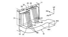
- FIG. 2 is a schematic top view of the battery pack 10 and the blower 30 disposed below the sheet 102.
- FIG. 3 is a schematic side view of the battery pack and the blower viewed from the direction of the FR direction in FIG.
- An arrow RH indicates a lateral direction orthogonal to the forward direction FR of the vehicle 100.
- the battery pack 10 has an upper case 11 and a lower case 12.
- the battery stack 20 is disposed in a space surrounded by the upper case 11 and the lower case 12.
- the battery stack 20 is fixed to the upper case 11 or the lower case 12.
- the battery case 20 is fixed to the floor panel P by fixing the lower case 12 to the floor panel P of the vehicle 100.
- Battery pack 10 can also be fixed to floor panel P via a bracket.
- the battery stack 20 corresponds to the power storage unit of the present invention.
- the battery stack 20 includes a plurality of unit cells 21, and the plurality of unit cells 21 are arranged in a predetermined direction (RH direction).
- the unit cell 21 corresponds to the power storage element of the present invention.
- the plurality of single cells 21 are electrically connected in series by a bus bar. Note that the battery stack 20 may include a plurality of single cells 21 electrically connected in parallel.
- a so-called square unit cell is used as the unit cell 21.
- the rectangular unit cell 21 is a unit cell having a plane perpendicular to the arrangement direction of the plurality of unit cells 21.
- a secondary battery such as a nickel metal hydride battery or a lithium ion battery can be used.
- an electric double layer capacitor (capacitor) can be used instead of the secondary battery.
- the plurality of unit cells 21 are arranged in one direction, but the present invention is not limited to this.
- one battery module can be constituted by two or more single cells, and a plurality of battery modules can be arranged in one direction (RH direction).
- a plurality of single cells included in one battery module can be electrically connected in series.
- a pair of end plates 22 are arranged at both ends of the battery stack 20 in a direction (RH direction) in which the plurality of single cells 21 are arranged side by side.
- the pair of end plates 22 sandwich the plurality of unit cells 21 constituting the battery stack 20, and are used to apply a binding force to the plurality of unit cells 21.
- the restraining force is a force that sandwiches the unit cell 21 in the RH direction.
- both ends of the restraining band 23 extending in the RH direction are connected to a pair of end plates 22.
- the end plate 22 is formed with a fixing portion 24 to which the restraining band 23 is coupled.
- the end portion of the restraining band 23 is coupled to the fixing portion 24 so that the restraining band 23 is connected to the end plate 22. Is done.
- the restraining band 23 is disposed on the upper surface and the lower surface of the battery stack 20.
- the position where the restraint band 23 is disposed can be set as appropriate, and both ends of the restraint band 23 only need to be connected to the pair of end plates 22.
- the restraining bands 23 can be disposed on both side surfaces of the battery stack 20 in the FR direction.
- a spacer (not shown) can be arranged between two unit cells 21 arranged adjacent to each other.
- the spacer is used to form a space between the two unit cells 21.
- the spacer can be formed of an insulating material such as resin.
- the space formed by the spacer is a space in which air for adjusting the temperature of the unit cell 21 moves.
- an intake passage S1 is formed on the upper surface of the battery stack 20, and an exhaust passage S2 is formed on the lower surface of the battery stack 20.
- the intake passage S ⁇ b> 1 is formed by the upper surface of the battery stack 20 and the upper case 11.
- the exhaust passage S ⁇ b> 2 is formed by the lower surface of the battery stack 20 and the lower case 12.
- a part (hereinafter referred to as a pedestal) 12a of the lower case 12 extends in the RH direction.
- a blower 30 is fixed to the base 12a. Accordingly, the battery pack 10 can be mounted on the vehicle 100 in a state where the blower 30 is attached to the base 12a (lower case 12). That is, the battery pack 10 and the blower 30 can be handled integrally, and the battery pack 10 and the blower 30 can be easily mounted on the vehicle 100.
- the base 12a of the present embodiment has a blower mounting portion 12b located on the lower surface of the blower 30 that is arranged adjacent to the side surface of the battery stack 20 in the RH direction.
- the pedestal 12 a is bent upward from the lower surface of the lower case 12 to the blower attachment portion 12 b, and the blower attachment portion 12 b is located above the lower surface of the lower case 12.
- the pedestal 12 a can be configured as a separate member from the lower case 12 and connected to the lower case 12, and the pedestal 12 b can be formed integrally with the lower case 12.
- the blower 30 is disposed adjacent to the side surface of the battery stack 20 in the RH direction. That is, the blower 30 is disposed adjacent to the direction in which the plurality of single cells 21 of the battery stack 20 are disposed side by side. In the present embodiment, for example, as shown in FIG. 2, the blower 30 is disposed on the main body exterior side of the vehicle 100 (for example, the vehicle side portion side in the RH direction) with respect to the battery stack 20.
- the outlet of the blower 30 is connected to the intake duct 32 via the duct 31.
- the intake duct 32 is disposed between the battery stack 10 and the blower 30 and is connected to the intake passage S ⁇ b> 1 of the battery pack 10.
- An intake duct 41 is connected to the inlet of the blower 30.
- An intake port is provided at an end of the intake duct 41 connected to the blower 30. The intake port of the intake duct 41 faces the vehicle interior.
- the blower 30 has a housing part 30A in which an outlet to which the duct 31 is connected and an inlet to which the intake duct 41 is connected, and a blower motor 30B accommodated in the housing part 30A.
- the blower motor 30B is a circular motor that is rotationally driven by electric power supplied to the blower motor 30B.
- the blower motor 30B is connected to a runner having a plurality of blade portions that are arranged in a cylindrical shape and are long in the direction of the rotation axis.
- the blower motor 30B is disposed adjacent to the battery pack 10 so that the rotation axis direction of the blower motor 30B is substantially parallel to the FR direction of the battery pack 10. That is, the blower 30 is disposed adjacent to the side surface of the battery pack 10 so that the rotation shaft of the blower motor 30B is in a direction substantially perpendicular to the RH direction.
- the intake duct 41 connected to the inlet of the blower 30 faces the front side of the seat 102 in the FR direction.
- the blower 30 takes in the intake air in the vehicle compartment from the FR direction substantially parallel to the rotation axis direction of the blower motor 30B, and flows it out in the RH direction substantially perpendicular to the rotation axis direction to the intake duct 32 (battery pack 10). Supply intake air.
- the air in the passenger compartment taken in from the intake duct 41 passes through the duct 31 and the intake duct 32 of the blower 30 and enters the intake passage S1.
- the air moved to the intake passage S1 enters the space formed by the spacer and moves from the upper surface of the battery stack 20 toward the lower surface.
- the air contacts the outer surface of the unit cell 21, and heat exchange is performed between the air and the unit cell 21.
- the unit cell 21 when the unit cell 21 is generating heat due to charging / discharging or the like, the temperature rise of the unit cell 21 can be suppressed by bringing cooling air into contact with the unit cell 21. Further, when the unit cell 21 is excessively cooled, the temperature drop of the unit cell 21 can be suppressed by bringing heating air into contact with the unit cell 21.
- the air in the passenger compartment is at a temperature suitable for temperature adjustment of the unit cell 21 by an air conditioner mounted on the vehicle 100 or the like. Therefore, if the air in the passenger compartment is supplied to the unit cell 21, the temperature of the unit cell 21 can be adjusted. By adjusting the temperature of the cell 21, it is possible to suppress the deterioration of the input / output characteristics of the cell 21.
- the air exchanged heat with the unit cell 21 moves to the exhaust passage S2. Since the exhaust duct 42 is connected to the exhaust passage S2, the air moved to the exhaust passage S2 is guided to the exhaust duct 42.
- the exhaust duct 42 moves air to the outside of the battery pack 10. For example, the exhaust duct 42 can exhaust air into the vehicle interior.
- an arrow indicated by a solid line indicates an intake path
- an arrow indicated by an alternate long and short dash line indicates an exhaust path.
- the exhaust duct 42 can be disposed in a space S3 between the battery pack 10 and the blower 30 attached to the pedestal 12a.
- the exhaust duct 42 is formed so that a part of the duct portion 42 ⁇ / b> A is disposed in the space S ⁇ b> 3 between the blower 30 and the battery pack 10 and extends rearward of the blower 30.
- An end portion of the exhaust duct 42 (a discharge port of the duct portion 42 ⁇ / b> A) can be connected to, for example, a garnish positioned in the lateral direction of the vehicle 100.
- the air that has moved through the exhaust duct 42 is returned to the passenger compartment through the garnish.
- the exhaust duct 42 can be arranged so that the discharge port is located in a luggage space or a space between the seat 102 and the side surface of the vehicle 100.
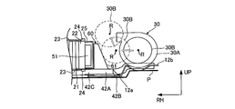
- the exhaust duct 42 of the present embodiment has a shape in which the duct portion 42A disposed in the space S3 guides the blower motor 30 that moves toward the battery pack 10 to the upper surface of the battery pack 10 when the blower 30 receives an external force. Is formed.
- the shape of the duct of the duct portion 42A may be formed so that the height increases in the UP direction from the connection port 42C connected to the exhaust port of the exhaust path S2 of the battery pack 10 toward the blower 30. it can. That is, the duct portion 42A has a height of the upper end Q of the duct portion 42A disposed in the space S3 with respect to the connection port 42C positioned below (for example, a height in the UP direction with respect to the lower surface of the floor panel P or the battery stack 20). ) Is high, and is formed in an inclined shape from the connection port 42C to the duct portion 42A.
- a monitoring unit 51 is disposed between the battery stack 20 and the blower 30 (between the battery stack 20 and the duct portion 42A).
- the monitoring unit 51 monitors the voltage and current of the battery stack 20. Specifically, a plurality of voltage sensors are attached to the battery stack 20, and the detection result of each voltage sensor is output to the monitoring unit 51.
- the voltage sensor can detect the voltage of each cell 21. Further, when the plurality of single cells 21 constituting the battery stack 20 are divided into a plurality of blocks, the voltage sensor can detect the voltage of each block. Each block includes a plurality of single cells 21.
- a current sensor is attached to the battery stack 20, and the detection result of the current sensor is output to the monitoring unit 51.
- the information monitored by the monitoring unit 51 is used to control charging / discharging of the battery stack 20. For example, when the voltage value (detected value) of the unit cell 21 reaches a preset upper limit value, charging / discharging of the battery stack 20 can be prohibited or suppressed. As a case where charging / discharging of the battery stack 20 is suppressed, the upper limit of the power value used for charging / discharging control can be changed in a decreasing direction.
- a relay 52 is disposed on the opposite side of the battery stack 20 from the side on which the monitoring unit 51 is disposed. That is, the monitoring unit 51 and the relay 52 can be arranged on both side surfaces of the battery stack 20 in the RH direction.
- the relay 52 allows charging / discharging of the battery stack 20 when in the on state, and prohibits charging / discharging of the battery stack 20 when in the off state.
- the current breaker 53 is used to cut off the current path of the battery pack 10.
- the current breaker 53 can be composed of a plug and a grip inserted into the plug, and the current path can be blocked by removing the grip from the plug.
- the current breaker 53 can be disposed on the side surface of the battery stack 20 where the relay 52 is disposed.
- the monitoring unit 51 can be attached to the end plate 22 of the battery stack 20.
- the protection member 25 has a space for accommodating the monitoring unit 51 and is formed to a predetermined thickness.
- the protection member 25 protects from an external force acting on the monitoring unit 51 attached to the end plate 22.
- the protection member 25 disposed so as to cover the monitoring unit 51 from the side surface in the RH direction of the end plate 22 is connected to the upper case 11 or the end plate 22. Further, the protection member 25 may be connected to the end plate 22 similarly to the monitoring unit 51.
- the protective member 25 has a convex portion 26 located on the restraining band 23 connected to the end plate 22 or the fixed portion 24 to which the restraining band 23 is coupled when attached to the battery pack 10.
- the convex part 26 is arrange
- the convex portion 26 is disposed adjacent to the restraining band 23 in the direction in which the plurality of unit cells 21 are disposed side by side. At this time, the end of the convex portion 26 may be in contact with the restraining band 23 or the fixing portion 24, and the convex portion 26 is at the same height as the restraining band 23 or the fixing portion 24 with a predetermined interval. It may be arranged.
- the convex portion 26 can be formed, for example, by projecting a plate-like wall portion 25A located above the monitoring unit 51 in the UP direction by drawing.
- the convex portion 26 functions as a reinforcing portion against an external force from the RH direction of the protection member 25.
- the convex portion 26 comes into contact with the restraining band 23 or the fixing portion 24, so that the deformation of the wall portion 25A is suppressed.
- the convex portion 26 prevents the space in which the monitoring unit 51 is accommodated from becoming narrow due to the deformation of the wall portion 25A.
- the convex part 26 is integrally formed with the protection member 25 in the present Example.
- the present invention is not limited to this, and the convex part 26 is individually attached to the wall part 25A. You may do it.
- the convex part 26 can also be comprised so that it may contact the end plate 22 instead of the fixing
- FIG. 4 is an external perspective view of the monitoring unit 51 disposed in the battery pack 10 and the protective member 25 that protects the monitoring unit 51.
- FIG. 5 is an external perspective view of the battery pack 10 and the exhaust duct 42.
- FIG. 6 is an external perspective view of the battery pack 10 and the blower 30.
- the monitoring unit 51 can be attached to the end plate 22 of the battery stack 20.
- the protection member 25 is attached so as to cover the monitoring unit 51 attached to the end plate 22 from the RH direction.
- the protection member 25 can be formed of a single plate-like member. A part of the wall portion (wall portion 25 ⁇ / b> B) corresponding to the monitoring unit 51 is formed in a concave shape, and a space for accommodating the monitoring unit 51 is formed between the end plate 22.
- the protection member 25 of the present embodiment is formed to have a size that covers the entire outer surface of the end plate 22, for example, it may have a size that covers only the monitoring unit 51.
- the duct portion 42 ⁇ / b> A of the exhaust duct 42 has a shape whose height increases in the UP direction from the connection port 42 ⁇ / b> C attached to the exhaust port of the exhaust path S ⁇ b> 2 of the battery pack 10 toward the blower 30. Yes.
- the upper end Q of the duct portion 42A is located above the upper surface of the duct connection port 42C.
- the duct portion 42A is provided with a fixing portion 42B connected to the base 12.
- the duct portion 42A is formed in a shape extending rearward of the blower 30 while being bent in the FR direction so as to bypass the blower 30 disposed adjacent to the battery pack 10 in the RH direction.
- the discharge port 42D of the exhaust duct 42 is disposed at a position adjacent to the blower 30 in the FR direction.
- the shape of the duct portion 42A is highly inclined in the UP direction from the connection port 42C toward the blower 30, but this is not restrictive.
- the duct portion 42A may have a rectangular shape or an arc shape that is higher in the UP direction than the connection port 42C, and the upper end Q of the duct portion 42A may not be inclined.
- the shape of the duct portion 42A disposed in the space S3 may be independent of the shape of the air flow path formed by the duct portion 42A. That is, the duct portion 42A may form an air flow path corresponding to the shape protruding in the UP direction in the space S3, and forms an air flow path independent of the shape protruding in the UP direction. It may be a thing.
- the intake duct 32 is connected to the intake path S1 of the battery pack 10, and the exhaust duct 42 is connected to the exhaust path S2 inserted through the intake path S1 of the battery pack.
- the blower 30 has a duct 31 connected to an intake duct 32 and is fixed to the blower mounting portion 12b of the base 12a.
- An intake duct 41 is connected to the inlet of the blower 30.
- FIG. 7 is a top view showing the positional relationship of the blower motor 30 ⁇ / b> B disposed adjacent to the battery stack 20 and the movement locus of the blower motor 30 in which an external force is applied to the blower 30.
- the blower 30 when the blower 30 receives an external force (force acting in the left-right direction of the vehicle 100), the blower 30 disposed on the pedestal 12 a facing the side surface in the RH direction of the battery stack 20 causes the battery stack 20 ( There is a risk of collision with the battery pack 10).
- the blower motor 30 of the blower 30 is a metal member such as iron and is harder than the housing portion 30A formed of a synthetic resin material or the like, the blower motor 30 is applied to the adjacent battery stack 20 by the external force received by the blower 30. May move and collide.
- the side door approaches the blower 30 due to deformation of the side door or deformation of the floor panel P. Since the blower 30 is disposed closer to the side door than the battery stack 20, an external force F may act on the blower 30 through the side door.
- the external force F1 is an external force that acts on the blower 30 substantially parallel to the RH direction.
- the blower motor 30B moves toward the battery stack 20 substantially parallel to the RH direction.
- the external force F2 is an external force that acts on the blower 30 obliquely from the rear side of the vehicle 100 with respect to the RH direction.
- the blower motor 30 ⁇ / b> B moves obliquely with respect to the RH direction toward the battery stack 20.
- blower motor 30B From the viewpoint of preventing the blower motor 30B from colliding with the battery stack 20, it is also important to prevent the blower 30 from colliding with the monitoring unit 51 arranged between the blower 30 and the battery stack 20. That is, when the blower motor 30B collides with the battery stack 20, the blower motor 30B may collide with the monitoring unit 51 disposed between the blower 30 and the battery stack 20.
- the blower motor 30 ⁇ / b> B when the blower motor 30 ⁇ / b> B receives the external force F ⁇ b> 1 and collides with the battery pack 10, the blower motor 30 ⁇ / b> B is shifted in the FR direction with respect to the monitoring unit 51 in order to avoid collision with the monitoring unit 51. It can be configured to be offset. However, if the blower motor 30B moves obliquely with respect to the RH direction toward the side surface of the battery stack 20 due to the external force F2, the blower motor 30B moves toward the monitoring unit 51 even if the monitoring unit 51 is offset. The unit 51 may collide.
- the protective member 25 is disposed in the monitoring unit 51 disposed on the side surface of the battery stack 20 between the blower 30 and the blower motor 30B collides with the side surface of the battery stack 20, the protective member 25, the monitoring unit 51 is protected to some extent.
- the monitoring unit 51 monitors the voltage and current of the battery stack 20 as described above, a high voltage line or the like may be connected, and the movement of the blower motor 30B that has received the external force F2 is similar to that of the battery stack 20. Need to be protected.
- the shape of the exhaust duct 42 arranged in the space S3 between the side surface of the battery stack 20 between the blower 30 and the blower 30 is devised, and the blower motor 30 receives the external force F1 or the external force F2.
- a collision avoidance unit that guides the movement locus of the blower motor 30 ⁇ / b> B in the upper surface direction of the battery stack 20 is provided.
- the duct portion 42A is integrally configured as a collision avoidance portion by forming the outer shape of the duct portion 42A of the exhaust duct 42 disposed in the space S3 so as to protrude in the UP direction.
- the blower motor 30 is prevented from colliding with the battery stack 20, and the collision between the monitoring unit 51 and the blower motor 30B disposed between the battery stack 20 and the blower 30 (duct part 42A) is avoided.
- FIG. 8 is a side view showing a movement locus of the blower motor 30B to which the external force F1 is applied in the AA sectional view of FIG.
- the exhaust duct 42 of the present embodiment is formed so that the upper end Q of the duct portion 42A disposed in the space S3 protrudes in the UP direction. That is, the upper end Q of the duct portion 42A is formed at a height that comes into contact with the peripheral surface of the blower motor 30 with respect to movement in the RH direction toward the battery stack 20 side surface of the blower motor 30B that has received external force.
- the blower motor 30B receiving the external force F1 moves toward the battery stack 20 in the RH direction
- the blower motor 30B comes into contact with the upper end Q of the duct portion 42A, and the blower motor 30B is substantially perpendicular to the side surface of the battery stack 20.
- the movement of the blower motor 30 ⁇ / b> B in the substantially vertical direction with respect to the side surface of the battery stack 20 is guided in the upper surface direction of the battery stack 20.
- the upper end Q of the duct portion 42A is lower than the center R (rotary shaft) of the blower motor 30 by a predetermined value in the UP direction. That is, the upper end Q of the duct part 42A is formed at a height lower by a predetermined value H1 than the position of the center R of the blower motor 30B in the UP direction from the lower surface of the floor panel P or the battery stack 20, and the duct part in the UP direction. 42A and the center R of the blower motor 30B are different from each other by a predetermined value H1.
- the predetermined value H1 can be a value smaller than the radius r of the blower motor 30B. Since the predetermined value H1 is smaller than the radius r of the blower motor 30B, the duct portion 42A is in contact with the blower motor 30B even if the duct portion 42A does not have a guide surface for guiding the blower motor 30B in the upper surface direction of the battery stack 20. In this case, the impact on the duct portion 42A is dispersed, and the upper end Q of the duct portion 42A becomes a jump stand, and the movement of the blower motor 30B in the substantially vertical direction with respect to the side surface of the battery stack 20 can be guided in the upper surface direction of the battery stack 20. .
- the predetermined value H1 can be appropriately set according to the angle at which the blower motor 30B after contacting the upper end Q of the duct portion 42A moves in the upper surface direction of the battery stack 20 without colliding with the battery stack 20. .
- FIG. 9 is a side view showing the positional relationship between the center R of the blower motor 30B and the exhaust duct 42 and the positional relationship between the center R of the blower motor 30B and the protective member 25 of the monitoring unit 51 in the BB cross-sectional view of FIG. is there.
- FIG. 9 is a side view showing the positional relationship between the center R of the blower motor 30B and the exhaust duct 42 and the positional relationship between the center R of the blower motor 30B and the protective member 25 of the monitoring unit 51 in the BB cross-sectional view of FIG. is there.
- FIG. 10 shows the positional relationship between the exhaust duct 42 on the side surface of the battery stack 20 where the monitoring unit 51 is disposed as viewed from the RH direction and the center R of the blower motor 30B, and the protective member where the center R of the blower motor 30B and the monitoring unit 51 are disposed.
- FIG. FIG. 11 is a diagram illustrating a movement locus of the blower motor 30B to which the external force F2 is applied.
- blower motor 30B offset behind the monitoring unit 51 in the FR direction is inclined with respect to the side of the battery stack 20 with respect to the RH direction. Moving. For this reason, the blower motor 30 ⁇ / b> B may collide with the monitoring unit 51 disposed on the outer surface of the end plate 22 between the battery stack 20 and the blower 30.
- Q in order to avoid the collision of the blower motor 30B with the monitoring unit 51, in other words, to prevent the blower motor 30B from colliding with the side wall portion 25B of the protective member 25 in which the monitoring unit 51 is accommodated, Q can be formed at a height that makes contact with the blower motor 30 with respect to movement in the RH direction toward the side surface of the battery stack 20 of the blower motor 30B that has received external force.
- the upper end Q of the duct portion 42A is formed in a shape having a height defined by the positional relationship with the upper end (wall portion 25A) of the monitoring unit 51. That is, when the upper end Q of the duct portion 42 is located at a distance larger than the radius r of the blower motor 30B with respect to the upper end in the UP direction of the monitoring unit 51 arranged in the battery stack 20, the side of the battery stack 20 is located. Therefore, the blower motor 30B moving in the substantially vertical direction collides with the wall portion 25B, and the monitoring unit 51 cannot be sufficiently protected.
- the distance in the UP direction between the upper end Q of the tact portion 42A disposed in the space S3 from the floor panel P or the battery stack 20 and the upper end of the monitoring unit 51 is a predetermined value H2 that is less than the radius r of the blower motor 30B.
- the height of the upper end Q of the duct portion 42A is defined.
- the shape of the duct part 42A is formed such that the upper end Q of the duct part 42A defined in this way is positioned so as to protrude between the battery stack 20 and the blower 30.
- the upper end Q of the duct unit 42A is placed between the battery stack 20 and the blower 30 so that the height of the upper end of the monitoring unit 51 is lower than the height obtained by adding the radius r of the blower motor 30B from the upper end Q of the duct unit 42A. It can be formed at a height protruding between them.
- the upper end Q of the duct portion 42A is located between the battery stack 20 and the blower 30 so that the height of the upper end of the monitoring unit 51 is lower than the height obtained by adding the radius r of the blower motor 30B from the upper end Q of the duct portion 42A. It is formed at a height that protrudes. For this reason, the blower motor 30B contacts the upper end Q of the duct portion 42A, and the blower motor 30B is prevented from moving in a substantially vertical direction with respect to the monitoring unit 51 (side surface of the battery stack 20). The movement of the blower motor 30 ⁇ / b> B in the substantially vertical direction with respect to the side surface of the monitoring unit 51 is guided in the upper surface direction of the battery stack 20. As shown in FIG. 11, by devising the shape of the exhaust duct 42 (duct part 42A), there is no need for additional parts, and the blower motor 30B can be avoided from colliding with the wall part 25B.
- the blower motor 30 ⁇ / b> B may come into contact with the wall portion 25 ⁇ / b> A of the protection member 25 that houses the monitoring unit 51.
- the height of the upper end Q of the duct portion 42A is defined in relation to the height of the upper end of the monitoring unit 51.
- the blower motor 30B can be prevented from colliding with the wall portion 25B, but the movement of the blower motor 30B in the upper surface direction of the battery stack 20 is blocked by the lower surface S of the sheet 102, and the blower motor 30B is protected by the protective member 25. That is, it may collide with the wall portion 25 ⁇ / b> A arranged on the upper end side of the monitoring unit 51.
- the convex portion 26 is disposed on the wall portion 25A.
- the convex portion 26 functions as a reinforcing portion against the impact received by the wall portion 25A, and the convex portion 26 can suppress deformation of the wall portion 25A due to the collision of the blower motor 30B and protect the monitoring unit 51.
- a convex portion 26 is arranged on the wall portion 25A arranged on the upper end side of the monitoring unit 51, and the convex portion 26 is formed to project upward by a predetermined height H3 from the wall portion 25A.
- the predetermined height H3 corresponds to the height from the wall portion 25A to the restraining band 23 or the fixing portion 24, and is convex to the restraining band 23 connected to the end plate 22 or the fixing portion 24 to which the restraining band 23 is coupled. 26 is arranged. Therefore, as shown in FIG.
- the end plate 22 is formed to have a strength that can withstand the impact caused by the blower motor 30 collision.
- the battery stack 20 can be protected from the collision of the blower motor 30B.
- the monitoring unit 51 cannot be sufficiently protected even if the protection member 25 is strengthened.
- the upper end Q of the duct portion 42A protrudes between the battery stack 20 and the blower 30 so that the height of the upper end of the unit 51 is lower than the height obtained by adding the radius r of the blower motor 30B from the upper end Q of the duct portion 42A.
- the exhaust duct 42 of the present embodiment has a height at which the upper end Q of the duct portion 42A is lower than the center R of the blower motor 30 by a predetermined value smaller than the radius r of the blower motor 30B in the UP direction.
- the upper end Q of the duct portion 42A protrudes between the battery stack 20 and the blower 30 such that the height of the upper end of the duct portion 42A is lower than the height obtained by adding the radius r of the blower motor 30B from the upper end Q of the duct portion 42A.
- the angle of the blower motor 30B that moves obliquely with respect to the RH direction by the external force F2 is as shown in FIG. If the angle is larger than the angle indicated by the two-dot chain line, the blower motor 30B deviates from the side surface of the battery stack 20 and does not collide. In this case, the upper end Q of the duct portion 42A is smaller than the radius r of the blower motor 30B in the UP direction than the center R of the blower motor 30 in the rearward region in the FR direction with respect to the monitoring unit 51.
- the upper end Q of the duct portion 42A is a battery so that the height is lower by a predetermined value or / and the height of the upper end of the monitoring unit 51 is lower than the height obtained by adding the radius r of the blower motor 30B from the upper end Q of the duct portion 42A.
- the upper end Q of the duct portion 42A disposed in a region farther from the blower motor 30B forward in the FR direction than the position indicated by the reference symbol Q1 with respect to the monitoring unit 51 is relative to the center R of the blower motor 30B and the upper end of the monitoring unit 51.
- the shape may not satisfy the positional relationship defined by the predetermined values H1 and H2.
- the entire upper end Q of 42 may have a shape that satisfies the positional relationship defined by the predetermined values H1 and H2 with respect to the center R of the blower motor 30B and the upper end of the monitoring unit 51.
- the intake passage S1 is provided on the upper surface side of the battery stack 20 and the exhaust passage S2 is provided on the lower surface side of the battery stack 20, but this is not restrictive. That is, an intake passage and an exhaust passage may be provided at a position sandwiching the battery stack 20.
- an exhaust passage can be provided on the upper surface side of the battery stack 20, and an intake passage can be provided on the lower surface side of the battery stack 20.
- the duct portion 42A arranged in the space S3 of the exhaust duct 42 connected to the exhaust passage guides the blower motor 30B in the direction of the lower surface of the battery stack 20, and the collision between the blower motor 30B and the battery stack 20 and the blower motor 30B A collision with the monitoring unit 51 can be similarly prevented.
- the exhaust duct 42 disposed between the battery stack 20 and the blower 30 has the collision avoidance portion, but is not limited thereto.
- a collision avoidance unit can be provided in the intake duct 32.
- the blower motor 30B is formed in the battery stack by forming the intake duct 32 in the same shape as the duct portion 42A. 20, the collision between the blower motor 30 ⁇ / b> B and the battery stack 20 (monitoring unit 51) can be prevented.
- the monitoring unit 51 is arranged between the battery stack 20 and the blower 30, but the present invention is not limited to this.
- a device used for charge / discharge control of the battery stack 20 can be arranged instead of the monitoring unit 51 or together with the monitoring unit 51.
- this device in addition to the monitoring unit 51, for example, there are a relay 52, a voltage sensor, a current sensor, and a temperature sensor.
- the temperature sensor is used to detect the temperature of the battery stack 20, and the detection result of the temperature sensor is used to control charging / discharging of the battery stack 20. Even in this case, it is possible to avoid the blower motor 30 ⁇ / b> B from colliding with the device disposed between the battery stack 20 and the blower 30.
- the monitoring unit 51 of the present embodiment is arranged on the left side of the end plate 22 in FIG. 7, but is not limited thereto.
- the end plate 22 can be arranged at the center or right side in the FR direction.
- the protection member 25 has a space for accommodating the monitoring unit 51 in accordance with the position of the monitoring unit 51 arranged on the end plate 22.
- FIG. 13 is an external perspective view showing the exhaust duct 42 provided with ribs (guide members) 60.
- ribs guide members
- symbol the same code
- the shape of the duct portion 42A of the exhaust duct 42 is formed higher in the UP direction in the space S3 between the battery pack 10 and the blower 30, but in the present embodiment, the upper end surface of the duct portion 42A.
- the upper end surface of the duct portion 42A are formed flat (planar), and a plurality of ribs 60 having guide surfaces 61 protruding in the UP direction are formed on the upper end surface of the duct portion 42A.
- the blower motor 30 that receives the external force F ⁇ b> 1 or the external force F ⁇ b> 2 and moves by the rib 60 is guided to the upper surface or the lower surface of the battery stack 20.
- the rib 60 is disposed between the side surface of the battery stack 20 and the blower 30.
- the rib 60 is formed in a trapezoidal shape extending from the upper end surface of the duct portion 42 ⁇ / b> A toward the upper surface of the battery stack 20.
- the guide surface 61 faces the blower 30 disposed adjacent to the battery stack 20 in the RH direction, and is inclined to the side surface side of the battery stack 20.
- the guide surface 61 that is inclined from the lower surface side of the battery stack 20 toward the upper surface side of the battery stack 20 guides the blower motor 30 ⁇ / b> B that has received an external force that moves relative to the side surface of the battery stack 20 in the upper surface direction of the battery stack 20. .
- a plurality of ribs 60 are arranged at a predetermined interval in the FR direction of the battery stack 20 so that the guide surface 61 faces the blower 30 as shown in FIG.
- a rib having a wide guide surface 61 in the FR direction of the battery stack 20 can be disposed.
- the inclination angle of the guide surface 61 can be set to an arbitrary angle that can guide the blower motor 30B in the upper surface direction of the battery stack 20 with respect to the collision of the blower motor 30B.
- the blower motor 30 ⁇ / b> B when the blower motor 30 ⁇ / b> B receives an external force, the blower motor 30 ⁇ / b> B moves toward the side surface of the battery stack 20 and contacts the guide surface 61 of the rib 60 arranged between the battery stack 20 and the blower 30.
- the blower motor 30 ⁇ / b> B that moves in a direction substantially perpendicular to the side surface of the battery stack 20 is guided in the upper surface direction of the battery stack 20 by the guide surface 61.
- the monitoring unit 51 and the protective member 25 can be disposed on the side surface of the battery stack 20 as in the first embodiment. In this case, the rib 60 is disposed closer to the blower 30 than the monitoring unit 51.
- the rib 60 disposed between the battery stack 20 and the blower 30 and formed in the duct portion 42A of the exhaust duct 42 is configured as the collision avoidance portion of the first embodiment, and the battery stack 20 and the monitoring unit are configured.
- the collision of the blower motor 30 ⁇ / b> B that has received an external force with respect to 51 can be prevented.
- the rib 60 is provided on the entire side surface of the battery stack 20, but the present invention is not limited to this.
- the blower motor 30B collides with the side surface of the battery stack 20 in a region other than the region where the monitoring unit 51 is disposed
- the blower motor 30B is formed by forming the end plate 22 so as to withstand the impact caused by the collision of the blower motor 30.
- the rib 60 is disposed in the region where the monitoring unit 51 is disposed without protecting the battery stack 20 from the collision and the rib 60 is disposed so as to avoid the blower motor 30B from colliding with the monitoring unit 51. You can also.
- the guide surface 61 of the rib 60 can be configured as a guide surface that guides the blower motor 30 that moves toward the side surface of the battery stack 20 by receiving an external force to the lower surface side of the battery stack 20.
- the guide surface 61 is not inclined toward the battery stack 20, but a rib 60 having the guide surface 61 inclined toward the blower 30 is disposed in the exhaust duct 42 or the intake duct 32.
- the blower motor 30 ⁇ / b> B can be guided to the lower surface side of the battery stack 20 through the guide surface 61.
- FIG. 15 is an external perspective view showing the exhaust duct 42 provided with ribs 70 (guide members).
- symbol is used and detailed description is abbreviate
- the shape of the duct portion 42 ⁇ / b> A of the exhaust duct 42 is formed higher in the UP direction in the space S ⁇ b> 3 between the battery pack 10 and the blower 30, or the rib 60 including the guide surface 61 is formed on the exhaust duct 42.
- the blower motor 30 that is moved by the external forces F1 and F2 is guided in the upper or lower direction of the battery stack 20, but the rib 70 of this embodiment is not in the vertical direction of the battery stack 20, but in the FR direction (
- the blower motor 30B is guided to the side of the battery stack 20 in the FR direction to prevent the battery stack 20 and the monitoring unit 51 from colliding.
- the upper end surface of the duct portion 42A is formed flat (planar), and the rib 70 is formed on the upper end surface of the duct portion 42A.
- the rib 70 is disposed between the side surface of the battery stack 20 and the blower 30.
- the rib 70 is a plate-like member inclined toward the battery stack 20 with the bent portion 71 extending in the UP direction as a vertex, and two plate-like ribs 70A extending in a substantially vertical direction (UP direction) from the upper end surface of the duct portion 42A. 70B. Both sides of the bent portion 71 of the rib 70 become plate-like ribs 70A and 70B.
- the rib 70 is formed as a wall portion that covers the side surface of the battery stack 20 with respect to the blower 30.
- the plate-like rib 70 ⁇ / b> A faces the blower 30 and faces the front side in the FR direction, and is inclined with respect to the side surface of the battery stack 20 facing the blower 30 from the bent portion 71.
- the plate-like rib 70 ⁇ / b> B faces the blower 30 and faces the rear side in the FR direction, and is inclined with respect to the side surface of the battery stack 20 facing the blower 30 from the bent portion 71.
- each inclination angle of plate-like rib 70A, 70B can be made into the arbitrary angles which can guide the blower motor 30B to the side surface direction in the FR direction of the battery stack 20 with respect to the collision of the blower motor 30B.
- the blower motor 30B receiving the external force F moves toward the battery stack 20 in the RH direction
- the blower motor 30B comes into contact with the rib 70 disposed between the battery stack 20 and the blower 30, and the plate-like rib 70A.
- the blower motor 30B that moves in a direction substantially perpendicular to the side surface of the battery stack 20 facing the blower 30 is guided to the front side in the FR direction of the battery stack 20 by the plate-like rib 70A.
- the blower motor 30B that moves in a direction substantially perpendicular to the side surface of the battery stack 20 facing the blower 30 is guided to the rear side in the FR direction of the battery stack 20 by the plate-shaped rib 70B.
- the monitoring unit 51 and the protective member 25 can be arranged on the side surface of the battery stack 20 facing the blower 30 as in the first embodiment. In this case, the rib 70 is closer to the blower 30 than the monitoring unit 51. Placed in.
- the rib 70 disposed between the battery stack 20 and the blower 30 and formed in the duct portion 42A of the exhaust duct 42 is configured as a collision avoidance portion of the first embodiment, and receives the external force.
- the battery stack 20 and the monitoring unit 51 can be prevented from colliding.
- the rib 70 is provided so as to cover the entire side surface of the battery stack 20 facing the blower 30, but the present invention is not limited to this.
- the blower motor 30B collides with the side surface of the battery stack 20 in a region other than the region where the monitoring unit 51 is disposed
- the blower motor 30B is formed by forming the end plate 22 so as to withstand the impact caused by the collision of the blower motor 30.
- the rib 70 is disposed in the region where the monitoring unit 51 is disposed without protecting the battery stack 20 from the collision and the rib 70 is disposed, and the blower motor 30B is prevented from colliding with the monitoring unit 51. You can also.
- Example 1-3 the case where the so-called square unit cell 21 is used has been described, but the present invention is not limited to this. That is, the configuration of the assembled battery arranged side by side with the blower 30 can be selected as appropriate.
- an assembled battery using a so-called cylindrical unit cell (corresponding to a power storage unit) can be used.
- a cylindrical unit cell is a unit cell in which a cross section perpendicular to the longitudinal direction is formed in a substantially circular shape.
- a single cell covered with a laminate film can be used as the single cell 21.
- an assembled battery (corresponding to a power storage unit) can be configured by stacking a plurality of cells.
- each of the rib 60 and the rib 70 can be arranged according to the shape of the upper end surface of the duct portion 42A.
Landscapes
- Engineering & Computer Science (AREA)
- Chemical & Material Sciences (AREA)
- Transportation (AREA)
- Mechanical Engineering (AREA)
- Power Engineering (AREA)
- Chemical Kinetics & Catalysis (AREA)
- General Chemical & Material Sciences (AREA)
- Electrochemistry (AREA)
- Sustainable Development (AREA)
- Life Sciences & Earth Sciences (AREA)
- Sustainable Energy (AREA)
- Manufacturing & Machinery (AREA)
- Combustion & Propulsion (AREA)
- Aviation & Aerospace Engineering (AREA)
- Battery Mounting, Suspending (AREA)
- Secondary Cells (AREA)
- Arrangement Or Mounting Of Propulsion Units For Vehicles (AREA)
- Cooling, Air Intake And Gas Exhaust, And Fuel Tank Arrangements In Propulsion Units (AREA)
Abstract
Description
図1から図11は、本発明の第1実施例を示す図である。図1は、車両の概略を示す側面図である。図1において、矢印FRは、車両の前進方向を示し、矢印UPは、車両の上方向を示している。
本発明の実施例2について、図13及び図14を用いて説明する。図13は、リブ(ガイド部材)60が設けられた排気ダクト42を示す外観斜視図である。なお、実施例1で説明した部材と同一の機能を有する部材については、同一符号を用い、詳細な説明は省略する。以下、実施例1と異なる点について、主に説明する。
本発明の実施例3について、図15及び図16を用いて説明する。図15は、リブ70(ガイド部材)が設けられた排気ダクト42を示す外観斜視図である。実施例1で説明した部材と同一の機能を有する部材については、同一符号を用い、詳細な説明は省略する。以下、実施例1と異なる点について、主に説明する。
Claims (9)
- 複数の蓄電素子を有し、車両の走行に用いられるエネルギを出力する蓄電ユニットと、
前記蓄電ユニットに対して車両本体の外装側に配置され、前記蓄電素子の温度を調節するための空気を前記蓄電ユニットに供給するブロワと、
前記蓄電ユニットと前記ブロアとの間に配置され、前記蓄電ユニット又は前記ブロアに接続されるダクトと、を有し、
前記ブロアは、前記蓄電ユニットに供給される空気の流れを形成するブロアモータを備えており、
前記ダクトは、外力を受けて前記蓄電ユニットに向かって移動する前記ブロアモータを、前記蓄電ユニットの上下方向又は側面方向にガイドする衝突回避部を有することを特徴とする車両。 - 外力を受けて前記蓄電ユニットに向かって移動する前記ブロアモータに接触する前記衝突回避部の上端は、前記ブロアモータの中心よりも下方に所定値低い高さに形成され、
前記所定値は、前記ブロアモータの半径よりも小さい値であることを特徴とする請求項1に記載の車両。 - 前記蓄電ユニットと前記ダクトとの間に配置され、前記蓄電ユニットの充放電制御に用いられる機器をさらに含み、
外力を受けて前記蓄電ユニットに向かって移動する前記ブロアモータと接触する前記衝突回避部の上端は、前記衝突回避部の上端よりも上方に位置する前記機器の上端との間の距離が前記ブロアモータの半径よりも短い高さに形成されていることを特徴とする請求項1又は2に記載の車両。 - 前記蓄電ユニットは、所定の方向に並んで配置される複数の前記蓄電素子を前記所定の方向において挟む一対のエンドプレートと、前記所定の方向に延び、両端が前記一対のエンドプレートに接続される連結部材と、を含んでおり、
前記ブロアに面する前記エンドプレートに配置された前記機器を保護する保護部材をさらに含み、
前記保護部材は、前記機器の上端に面する壁部に配置され、前記所定の方向において前記連結部材と隣接する凸部を有することを特徴とする請求項3に記載の車両。 - 前記衝突回避部は、前記ダクトの外形を前記蓄電ユニットと前記ブロアとの間のスペースに突出させた形状に形成することで、前記ダクトに一体的に設けられることを特徴とする請求項2から4のいずれか1つに記載の車両。
- 前記衝突回避部は、前記ダクトに形成されるリブであることを特徴とする請求項1に記載の車両。
- 前記蓄電ユニットの周囲に前記空気の流通経路を形成するケースをさらに含み、
前記ダクトは、前記流通経路の排気口に接続される排気ダクトであることを特徴とする請求項1から6のいずれか1つに記載の車両。 - 前記複数の蓄電素子は、所定の方向に並んでおり、
前記所定の方向に、前記蓄電ユニットおよび前記ブロワが並んでいることを特徴とする請求項1から7のいずれか1つに記載の車両。 - 前記蓄電ユニットは、シートクッションの下方に形成されたスペースに配置されていることを特徴とする請求項1から8のいずれか1つに記載の車両。
Priority Applications (5)
| Application Number | Priority Date | Filing Date | Title |
|---|---|---|---|
| US14/398,288 US10286775B2 (en) | 2012-05-17 | 2012-05-17 | Vehicle |
| PCT/JP2012/003245 WO2013171797A1 (ja) | 2012-05-17 | 2012-05-17 | 車両 |
| CN201280073230.XA CN104302501B (zh) | 2012-05-17 | 2012-05-17 | 车辆 |
| EP12876881.9A EP2851230B1 (en) | 2012-05-17 | 2012-05-17 | Vehicle |
| JP2014515353A JP5854129B2 (ja) | 2012-05-17 | 2012-05-17 | 車両 |
Applications Claiming Priority (1)
| Application Number | Priority Date | Filing Date | Title |
|---|---|---|---|
| PCT/JP2012/003245 WO2013171797A1 (ja) | 2012-05-17 | 2012-05-17 | 車両 |
Publications (1)
| Publication Number | Publication Date |
|---|---|
| WO2013171797A1 true WO2013171797A1 (ja) | 2013-11-21 |
Family
ID=49583251
Family Applications (1)
| Application Number | Title | Priority Date | Filing Date |
|---|---|---|---|
| PCT/JP2012/003245 WO2013171797A1 (ja) | 2012-05-17 | 2012-05-17 | 車両 |
Country Status (5)
| Country | Link |
|---|---|
| US (1) | US10286775B2 (ja) |
| EP (1) | EP2851230B1 (ja) |
| JP (1) | JP5854129B2 (ja) |
| CN (1) | CN104302501B (ja) |
| WO (1) | WO2013171797A1 (ja) |
Cited By (4)
| Publication number | Priority date | Publication date | Assignee | Title |
|---|---|---|---|---|
| JP2016066558A (ja) * | 2014-09-26 | 2016-04-28 | いすゞ自動車株式会社 | バッテリユニットボックスの通気口カバー |
| JP2018030448A (ja) * | 2016-08-24 | 2018-03-01 | 本田技研工業株式会社 | 車両 |
| JP2020119884A (ja) * | 2019-01-25 | 2020-08-06 | トヨタ自動車株式会社 | 蓄電スタックの冷却構造および蓄電スタックの冷却システム |
| DE102015205255B4 (de) | 2014-03-28 | 2024-03-28 | Subaru Corporation | Schutzstruktur für ein in einem hinteren Teil einer Fahrzeugkarosserie angeordnetes Batteriemodul |
Families Citing this family (6)
| Publication number | Priority date | Publication date | Assignee | Title |
|---|---|---|---|---|
| US11380918B2 (en) * | 2014-08-20 | 2022-07-05 | University of Pittsburgh—of the Commonwealth System of Higher Education | System and method for monitoring a reactor system using optical fiber based sensors |
| US10370035B2 (en) * | 2016-12-08 | 2019-08-06 | Inevit Llc | Motor guidance component configured to direct movement of a dislodged electric motor of an electric vehicle in response to crash forces |
| CN109204560B (zh) * | 2017-06-30 | 2021-02-23 | 比亚迪股份有限公司 | 电动汽车及其车身结构 |
| JP7047419B2 (ja) * | 2018-02-01 | 2022-04-05 | トヨタ自動車株式会社 | 車両用クーラ装置 |
| US11509003B2 (en) * | 2019-01-25 | 2022-11-22 | Toyota Jidosha Kabushiki Kaisha | Cooling structure for power storage stack and cooling system for power storage stack |
| US11618474B2 (en) | 2020-10-12 | 2023-04-04 | David W. Carroll | Autonomous electronic vehicle (AV) inertia reduction and safest path direction system |
Citations (10)
| Publication number | Priority date | Publication date | Assignee | Title |
|---|---|---|---|---|
| JP2002186101A (ja) | 2000-12-14 | 2002-06-28 | Toyota Auto Body Co Ltd | 補機用バッテリの保護構造 |
| JP2003346759A (ja) | 2002-05-23 | 2003-12-05 | Toyota Motor Corp | 電池システム |
| JP2004262412A (ja) | 2003-03-04 | 2004-09-24 | Fuji Heavy Ind Ltd | バッテリの取付構造 |
| JP2004288527A (ja) | 2003-03-24 | 2004-10-14 | Panasonic Ev Energy Co Ltd | 電池パック |
| JP2006109542A (ja) * | 2004-09-30 | 2006-04-20 | Sanyo Electric Co Ltd | 車両用の電源装置 |
| JP2006224874A (ja) | 2005-02-18 | 2006-08-31 | Nissan Motor Co Ltd | 燃料電池車の部品配置構造 |
| JP2008260382A (ja) | 2007-04-11 | 2008-10-30 | Toyota Motor Corp | 車両 |
| JP2008265470A (ja) * | 2007-04-18 | 2008-11-06 | Toyota Motor Corp | 車両に搭載された電気機器の冷却装置 |
| JP2011020552A (ja) * | 2009-07-15 | 2011-02-03 | Toyota Motor Corp | 車両用電気機器の冷却ユニットの搭載方法及び車載用電気機器の冷却ユニット |
| WO2012056492A1 (ja) * | 2010-10-26 | 2012-05-03 | トヨタ自動車株式会社 | 車両 |
Family Cites Families (3)
| Publication number | Priority date | Publication date | Assignee | Title |
|---|---|---|---|---|
| JP2009252688A (ja) * | 2008-04-10 | 2009-10-29 | Toyota Motor Corp | 車両用蓄電池の温調システム |
| JP2011009610A (ja) * | 2009-06-29 | 2011-01-13 | Sharp Corp | 窒化物半導体レーザ素子及びウェハ |
| JP5617200B2 (ja) * | 2009-07-17 | 2014-11-05 | 日産自動車株式会社 | バッテリーパック |
-
2012
- 2012-05-17 US US14/398,288 patent/US10286775B2/en not_active Expired - Fee Related
- 2012-05-17 JP JP2014515353A patent/JP5854129B2/ja active Active
- 2012-05-17 CN CN201280073230.XA patent/CN104302501B/zh active Active
- 2012-05-17 WO PCT/JP2012/003245 patent/WO2013171797A1/ja active Application Filing
- 2012-05-17 EP EP12876881.9A patent/EP2851230B1/en active Active
Patent Citations (10)
| Publication number | Priority date | Publication date | Assignee | Title |
|---|---|---|---|---|
| JP2002186101A (ja) | 2000-12-14 | 2002-06-28 | Toyota Auto Body Co Ltd | 補機用バッテリの保護構造 |
| JP2003346759A (ja) | 2002-05-23 | 2003-12-05 | Toyota Motor Corp | 電池システム |
| JP2004262412A (ja) | 2003-03-04 | 2004-09-24 | Fuji Heavy Ind Ltd | バッテリの取付構造 |
| JP2004288527A (ja) | 2003-03-24 | 2004-10-14 | Panasonic Ev Energy Co Ltd | 電池パック |
| JP2006109542A (ja) * | 2004-09-30 | 2006-04-20 | Sanyo Electric Co Ltd | 車両用の電源装置 |
| JP2006224874A (ja) | 2005-02-18 | 2006-08-31 | Nissan Motor Co Ltd | 燃料電池車の部品配置構造 |
| JP2008260382A (ja) | 2007-04-11 | 2008-10-30 | Toyota Motor Corp | 車両 |
| JP2008265470A (ja) * | 2007-04-18 | 2008-11-06 | Toyota Motor Corp | 車両に搭載された電気機器の冷却装置 |
| JP2011020552A (ja) * | 2009-07-15 | 2011-02-03 | Toyota Motor Corp | 車両用電気機器の冷却ユニットの搭載方法及び車載用電気機器の冷却ユニット |
| WO2012056492A1 (ja) * | 2010-10-26 | 2012-05-03 | トヨタ自動車株式会社 | 車両 |
Non-Patent Citations (1)
| Title |
|---|
| See also references of EP2851230A4 |
Cited By (6)
| Publication number | Priority date | Publication date | Assignee | Title |
|---|---|---|---|---|
| DE102015205255B4 (de) | 2014-03-28 | 2024-03-28 | Subaru Corporation | Schutzstruktur für ein in einem hinteren Teil einer Fahrzeugkarosserie angeordnetes Batteriemodul |
| JP2016066558A (ja) * | 2014-09-26 | 2016-04-28 | いすゞ自動車株式会社 | バッテリユニットボックスの通気口カバー |
| JP2018030448A (ja) * | 2016-08-24 | 2018-03-01 | 本田技研工業株式会社 | 車両 |
| US10583714B2 (en) | 2016-08-24 | 2020-03-10 | Honda Motor Co., Ltd. | Vehicle |
| JP2020119884A (ja) * | 2019-01-25 | 2020-08-06 | トヨタ自動車株式会社 | 蓄電スタックの冷却構造および蓄電スタックの冷却システム |
| JP7200907B2 (ja) | 2019-01-25 | 2023-01-10 | トヨタ自動車株式会社 | 蓄電スタックの冷却構造および蓄電スタックの冷却システム |
Also Published As
| Publication number | Publication date |
|---|---|
| US10286775B2 (en) | 2019-05-14 |
| EP2851230A1 (en) | 2015-03-25 |
| EP2851230B1 (en) | 2019-12-04 |
| JPWO2013171797A1 (ja) | 2016-01-07 |
| EP2851230A4 (en) | 2016-01-20 |
| CN104302501A (zh) | 2015-01-21 |
| CN104302501B (zh) | 2017-03-22 |
| JP5854129B2 (ja) | 2016-02-09 |
| US20150133041A1 (en) | 2015-05-14 |
Similar Documents
| Publication | Publication Date | Title |
|---|---|---|
| JP5854129B2 (ja) | 車両 | |
| JP5370582B2 (ja) | 車両 | |
| JP5212482B2 (ja) | 電源装置の搭載構造 | |
| JP4576931B2 (ja) | 電気機器の搭載構造 | |
| KR101810091B1 (ko) | 차량 탑재 전지 | |
| EP3201970B1 (en) | Battery module vent system and method | |
| JP5447676B2 (ja) | 車両および蓄電装置 | |
| JP5040905B2 (ja) | 蓄電装置の温度調節構造 | |
| JP2007069801A (ja) | 電源装置の車両搭載構造 | |
| JP2008234870A (ja) | バッテリの車両搭載構造 | |
| JP2020047465A (ja) | 車載用バッテリ | |
| JP7160613B2 (ja) | 車載用バッテリ | |
| US20230072733A1 (en) | Battery module and battery pack including battery modules | |
| US20190020080A1 (en) | Vehicle battery pack | |
| JP2014083882A (ja) | 車両 | |
| JP7312075B2 (ja) | バッテリ保護構造 | |
| US20190393566A1 (en) | Battery-pack storage structure | |
| JP2023069332A (ja) | 車両後部構造 | |
| CN115805797A (zh) | 电池支承构造体 | |
| JP2013187124A (ja) | 蓄電装置 |
Legal Events
| Date | Code | Title | Description |
|---|---|---|---|
| 121 | Ep: the epo has been informed by wipo that ep was designated in this application |
Ref document number: 12876881 Country of ref document: EP Kind code of ref document: A1 |
|
| ENP | Entry into the national phase |
Ref document number: 2014515353 Country of ref document: JP Kind code of ref document: A |
|
| WWE | Wipo information: entry into national phase |
Ref document number: 14398288 Country of ref document: US |
|
| WWE | Wipo information: entry into national phase |
Ref document number: 2012876881 Country of ref document: EP |
|
| NENP | Non-entry into the national phase |
Ref country code: DE |