EP2851230A1 - Vehicle - Google Patents
Vehicle Download PDFInfo
- Publication number
- EP2851230A1 EP2851230A1 EP20120876881 EP12876881A EP2851230A1 EP 2851230 A1 EP2851230 A1 EP 2851230A1 EP 20120876881 EP20120876881 EP 20120876881 EP 12876881 A EP12876881 A EP 12876881A EP 2851230 A1 EP2851230 A1 EP 2851230A1
- Authority
- EP
- European Patent Office
- Prior art keywords
- blower
- electric storage
- storage unit
- blower motor
- duct
- Prior art date
- Legal status (The legal status is an assumption and is not a legal conclusion. Google has not performed a legal analysis and makes no representation as to the accuracy of the status listed.)
- Granted
Links
- 230000008878 coupling Effects 0.000 claims description 4
- 238000010168 coupling process Methods 0.000 claims description 4
- 238000005859 coupling reaction Methods 0.000 claims description 4
- 230000001965 increasing effect Effects 0.000 description 7
- 230000035939 shock Effects 0.000 description 6
- 125000006850 spacer group Chemical group 0.000 description 5
- 238000001514 detection method Methods 0.000 description 4
- 238000010586 diagram Methods 0.000 description 3
- XEEYBQQBJWHFJM-UHFFFAOYSA-N Iron Chemical compound [Fe] XEEYBQQBJWHFJM-UHFFFAOYSA-N 0.000 description 2
- 230000006866 deterioration Effects 0.000 description 2
- 235000021189 garnishes Nutrition 0.000 description 2
- 238000000034 method Methods 0.000 description 2
- 230000002787 reinforcement Effects 0.000 description 2
- HBBGRARXTFLTSG-UHFFFAOYSA-N Lithium ion Chemical compound [Li+] HBBGRARXTFLTSG-UHFFFAOYSA-N 0.000 description 1
- 239000003990 capacitor Substances 0.000 description 1
- 238000002485 combustion reaction Methods 0.000 description 1
- 238000001816 cooling Methods 0.000 description 1
- 230000000694 effects Effects 0.000 description 1
- 230000002708 enhancing effect Effects 0.000 description 1
- 239000000446 fuel Substances 0.000 description 1
- 238000010438 heat treatment Methods 0.000 description 1
- 239000011810 insulating material Substances 0.000 description 1
- 229910052742 iron Inorganic materials 0.000 description 1
- 229910001416 lithium ion Inorganic materials 0.000 description 1
- 229910052987 metal hydride Inorganic materials 0.000 description 1
- 229910052759 nickel Inorganic materials 0.000 description 1
- PXHVJJICTQNCMI-UHFFFAOYSA-N nickel Substances [Ni] PXHVJJICTQNCMI-UHFFFAOYSA-N 0.000 description 1
- -1 nickel metal hydride Chemical class 0.000 description 1
- 230000002265 prevention Effects 0.000 description 1
- 229920005989 resin Polymers 0.000 description 1
- 239000011347 resin Substances 0.000 description 1
- 229920003002 synthetic resin Polymers 0.000 description 1
- 239000000057 synthetic resin Substances 0.000 description 1
Images


Classifications
-
- B—PERFORMING OPERATIONS; TRANSPORTING
- B60—VEHICLES IN GENERAL
- B60K—ARRANGEMENT OR MOUNTING OF PROPULSION UNITS OR OF TRANSMISSIONS IN VEHICLES; ARRANGEMENT OR MOUNTING OF PLURAL DIVERSE PRIME-MOVERS IN VEHICLES; AUXILIARY DRIVES FOR VEHICLES; INSTRUMENTATION OR DASHBOARDS FOR VEHICLES; ARRANGEMENTS IN CONNECTION WITH COOLING, AIR INTAKE, GAS EXHAUST OR FUEL SUPPLY OF PROPULSION UNITS IN VEHICLES
- B60K11/00—Arrangement in connection with cooling of propulsion units
- B60K11/06—Arrangement in connection with cooling of propulsion units with air cooling
-
- B—PERFORMING OPERATIONS; TRANSPORTING
- B60—VEHICLES IN GENERAL
- B60K—ARRANGEMENT OR MOUNTING OF PROPULSION UNITS OR OF TRANSMISSIONS IN VEHICLES; ARRANGEMENT OR MOUNTING OF PLURAL DIVERSE PRIME-MOVERS IN VEHICLES; AUXILIARY DRIVES FOR VEHICLES; INSTRUMENTATION OR DASHBOARDS FOR VEHICLES; ARRANGEMENTS IN CONNECTION WITH COOLING, AIR INTAKE, GAS EXHAUST OR FUEL SUPPLY OF PROPULSION UNITS IN VEHICLES
- B60K1/00—Arrangement or mounting of electrical propulsion units
- B60K1/04—Arrangement or mounting of electrical propulsion units of the electric storage means for propulsion
-
- B—PERFORMING OPERATIONS; TRANSPORTING
- B60—VEHICLES IN GENERAL
- B60L—PROPULSION OF ELECTRICALLY-PROPELLED VEHICLES; SUPPLYING ELECTRIC POWER FOR AUXILIARY EQUIPMENT OF ELECTRICALLY-PROPELLED VEHICLES; ELECTRODYNAMIC BRAKE SYSTEMS FOR VEHICLES IN GENERAL; MAGNETIC SUSPENSION OR LEVITATION FOR VEHICLES; MONITORING OPERATING VARIABLES OF ELECTRICALLY-PROPELLED VEHICLES; ELECTRIC SAFETY DEVICES FOR ELECTRICALLY-PROPELLED VEHICLES
- B60L1/00—Supplying electric power to auxiliary equipment of vehicles
- B60L1/003—Supplying electric power to auxiliary equipment of vehicles to auxiliary motors, e.g. for pumps, compressors
-
- B—PERFORMING OPERATIONS; TRANSPORTING
- B60—VEHICLES IN GENERAL
- B60L—PROPULSION OF ELECTRICALLY-PROPELLED VEHICLES; SUPPLYING ELECTRIC POWER FOR AUXILIARY EQUIPMENT OF ELECTRICALLY-PROPELLED VEHICLES; ELECTRODYNAMIC BRAKE SYSTEMS FOR VEHICLES IN GENERAL; MAGNETIC SUSPENSION OR LEVITATION FOR VEHICLES; MONITORING OPERATING VARIABLES OF ELECTRICALLY-PROPELLED VEHICLES; ELECTRIC SAFETY DEVICES FOR ELECTRICALLY-PROPELLED VEHICLES
- B60L3/00—Electric devices on electrically-propelled vehicles for safety purposes; Monitoring operating variables, e.g. speed, deceleration or energy consumption
- B60L3/0007—Measures or means for preventing or attenuating collisions
-
- B—PERFORMING OPERATIONS; TRANSPORTING
- B60—VEHICLES IN GENERAL
- B60L—PROPULSION OF ELECTRICALLY-PROPELLED VEHICLES; SUPPLYING ELECTRIC POWER FOR AUXILIARY EQUIPMENT OF ELECTRICALLY-PROPELLED VEHICLES; ELECTRODYNAMIC BRAKE SYSTEMS FOR VEHICLES IN GENERAL; MAGNETIC SUSPENSION OR LEVITATION FOR VEHICLES; MONITORING OPERATING VARIABLES OF ELECTRICALLY-PROPELLED VEHICLES; ELECTRIC SAFETY DEVICES FOR ELECTRICALLY-PROPELLED VEHICLES
- B60L50/00—Electric propulsion with power supplied within the vehicle
- B60L50/50—Electric propulsion with power supplied within the vehicle using propulsion power supplied by batteries or fuel cells
- B60L50/51—Electric propulsion with power supplied within the vehicle using propulsion power supplied by batteries or fuel cells characterised by AC-motors
-
- B—PERFORMING OPERATIONS; TRANSPORTING
- B60—VEHICLES IN GENERAL
- B60L—PROPULSION OF ELECTRICALLY-PROPELLED VEHICLES; SUPPLYING ELECTRIC POWER FOR AUXILIARY EQUIPMENT OF ELECTRICALLY-PROPELLED VEHICLES; ELECTRODYNAMIC BRAKE SYSTEMS FOR VEHICLES IN GENERAL; MAGNETIC SUSPENSION OR LEVITATION FOR VEHICLES; MONITORING OPERATING VARIABLES OF ELECTRICALLY-PROPELLED VEHICLES; ELECTRIC SAFETY DEVICES FOR ELECTRICALLY-PROPELLED VEHICLES
- B60L50/00—Electric propulsion with power supplied within the vehicle
- B60L50/50—Electric propulsion with power supplied within the vehicle using propulsion power supplied by batteries or fuel cells
- B60L50/60—Electric propulsion with power supplied within the vehicle using propulsion power supplied by batteries or fuel cells using power supplied by batteries
- B60L50/64—Constructional details of batteries specially adapted for electric vehicles
-
- B—PERFORMING OPERATIONS; TRANSPORTING
- B60—VEHICLES IN GENERAL
- B60L—PROPULSION OF ELECTRICALLY-PROPELLED VEHICLES; SUPPLYING ELECTRIC POWER FOR AUXILIARY EQUIPMENT OF ELECTRICALLY-PROPELLED VEHICLES; ELECTRODYNAMIC BRAKE SYSTEMS FOR VEHICLES IN GENERAL; MAGNETIC SUSPENSION OR LEVITATION FOR VEHICLES; MONITORING OPERATING VARIABLES OF ELECTRICALLY-PROPELLED VEHICLES; ELECTRIC SAFETY DEVICES FOR ELECTRICALLY-PROPELLED VEHICLES
- B60L50/00—Electric propulsion with power supplied within the vehicle
- B60L50/50—Electric propulsion with power supplied within the vehicle using propulsion power supplied by batteries or fuel cells
- B60L50/60—Electric propulsion with power supplied within the vehicle using propulsion power supplied by batteries or fuel cells using power supplied by batteries
- B60L50/66—Arrangements of batteries
-
- B—PERFORMING OPERATIONS; TRANSPORTING
- B60—VEHICLES IN GENERAL
- B60L—PROPULSION OF ELECTRICALLY-PROPELLED VEHICLES; SUPPLYING ELECTRIC POWER FOR AUXILIARY EQUIPMENT OF ELECTRICALLY-PROPELLED VEHICLES; ELECTRODYNAMIC BRAKE SYSTEMS FOR VEHICLES IN GENERAL; MAGNETIC SUSPENSION OR LEVITATION FOR VEHICLES; MONITORING OPERATING VARIABLES OF ELECTRICALLY-PROPELLED VEHICLES; ELECTRIC SAFETY DEVICES FOR ELECTRICALLY-PROPELLED VEHICLES
- B60L58/00—Methods or circuit arrangements for monitoring or controlling batteries or fuel cells, specially adapted for electric vehicles
- B60L58/10—Methods or circuit arrangements for monitoring or controlling batteries or fuel cells, specially adapted for electric vehicles for monitoring or controlling batteries
- B60L58/18—Methods or circuit arrangements for monitoring or controlling batteries or fuel cells, specially adapted for electric vehicles for monitoring or controlling batteries of two or more battery modules
- B60L58/21—Methods or circuit arrangements for monitoring or controlling batteries or fuel cells, specially adapted for electric vehicles for monitoring or controlling batteries of two or more battery modules having the same nominal voltage
-
- B—PERFORMING OPERATIONS; TRANSPORTING
- B60—VEHICLES IN GENERAL
- B60L—PROPULSION OF ELECTRICALLY-PROPELLED VEHICLES; SUPPLYING ELECTRIC POWER FOR AUXILIARY EQUIPMENT OF ELECTRICALLY-PROPELLED VEHICLES; ELECTRODYNAMIC BRAKE SYSTEMS FOR VEHICLES IN GENERAL; MAGNETIC SUSPENSION OR LEVITATION FOR VEHICLES; MONITORING OPERATING VARIABLES OF ELECTRICALLY-PROPELLED VEHICLES; ELECTRIC SAFETY DEVICES FOR ELECTRICALLY-PROPELLED VEHICLES
- B60L58/00—Methods or circuit arrangements for monitoring or controlling batteries or fuel cells, specially adapted for electric vehicles
- B60L58/10—Methods or circuit arrangements for monitoring or controlling batteries or fuel cells, specially adapted for electric vehicles for monitoring or controlling batteries
- B60L58/24—Methods or circuit arrangements for monitoring or controlling batteries or fuel cells, specially adapted for electric vehicles for monitoring or controlling batteries for controlling the temperature of batteries
- B60L58/26—Methods or circuit arrangements for monitoring or controlling batteries or fuel cells, specially adapted for electric vehicles for monitoring or controlling batteries for controlling the temperature of batteries by cooling
-
- H—ELECTRICITY
- H01—ELECTRIC ELEMENTS
- H01M—PROCESSES OR MEANS, e.g. BATTERIES, FOR THE DIRECT CONVERSION OF CHEMICAL ENERGY INTO ELECTRICAL ENERGY
- H01M10/00—Secondary cells; Manufacture thereof
- H01M10/60—Heating or cooling; Temperature control
- H01M10/61—Types of temperature control
- H01M10/613—Cooling or keeping cold
-
- H—ELECTRICITY
- H01—ELECTRIC ELEMENTS
- H01M—PROCESSES OR MEANS, e.g. BATTERIES, FOR THE DIRECT CONVERSION OF CHEMICAL ENERGY INTO ELECTRICAL ENERGY
- H01M10/00—Secondary cells; Manufacture thereof
- H01M10/60—Heating or cooling; Temperature control
- H01M10/62—Heating or cooling; Temperature control specially adapted for specific applications
- H01M10/625—Vehicles
-
- H—ELECTRICITY
- H01—ELECTRIC ELEMENTS
- H01M—PROCESSES OR MEANS, e.g. BATTERIES, FOR THE DIRECT CONVERSION OF CHEMICAL ENERGY INTO ELECTRICAL ENERGY
- H01M10/00—Secondary cells; Manufacture thereof
- H01M10/60—Heating or cooling; Temperature control
- H01M10/65—Means for temperature control structurally associated with the cells
- H01M10/656—Means for temperature control structurally associated with the cells characterised by the type of heat-exchange fluid
- H01M10/6561—Gases
- H01M10/6563—Gases with forced flow, e.g. by blowers
-
- H—ELECTRICITY
- H01—ELECTRIC ELEMENTS
- H01M—PROCESSES OR MEANS, e.g. BATTERIES, FOR THE DIRECT CONVERSION OF CHEMICAL ENERGY INTO ELECTRICAL ENERGY
- H01M10/00—Secondary cells; Manufacture thereof
- H01M10/60—Heating or cooling; Temperature control
- H01M10/66—Heat-exchange relationships between the cells and other systems, e.g. central heating systems or fuel cells
-
- H—ELECTRICITY
- H01—ELECTRIC ELEMENTS
- H01M—PROCESSES OR MEANS, e.g. BATTERIES, FOR THE DIRECT CONVERSION OF CHEMICAL ENERGY INTO ELECTRICAL ENERGY
- H01M50/00—Constructional details or processes of manufacture of the non-active parts of electrochemical cells other than fuel cells, e.g. hybrid cells
- H01M50/20—Mountings; Secondary casings or frames; Racks, modules or packs; Suspension devices; Shock absorbers; Transport or carrying devices; Holders
- H01M50/204—Racks, modules or packs for multiple batteries or multiple cells
-
- H—ELECTRICITY
- H01—ELECTRIC ELEMENTS
- H01M—PROCESSES OR MEANS, e.g. BATTERIES, FOR THE DIRECT CONVERSION OF CHEMICAL ENERGY INTO ELECTRICAL ENERGY
- H01M50/00—Constructional details or processes of manufacture of the non-active parts of electrochemical cells other than fuel cells, e.g. hybrid cells
- H01M50/20—Mountings; Secondary casings or frames; Racks, modules or packs; Suspension devices; Shock absorbers; Transport or carrying devices; Holders
- H01M50/233—Mountings; Secondary casings or frames; Racks, modules or packs; Suspension devices; Shock absorbers; Transport or carrying devices; Holders characterised by physical properties of casings or racks, e.g. dimensions
- H01M50/24—Mountings; Secondary casings or frames; Racks, modules or packs; Suspension devices; Shock absorbers; Transport or carrying devices; Holders characterised by physical properties of casings or racks, e.g. dimensions adapted for protecting batteries from their environment, e.g. from corrosion
-
- H—ELECTRICITY
- H01—ELECTRIC ELEMENTS
- H01M—PROCESSES OR MEANS, e.g. BATTERIES, FOR THE DIRECT CONVERSION OF CHEMICAL ENERGY INTO ELECTRICAL ENERGY
- H01M50/00—Constructional details or processes of manufacture of the non-active parts of electrochemical cells other than fuel cells, e.g. hybrid cells
- H01M50/20—Mountings; Secondary casings or frames; Racks, modules or packs; Suspension devices; Shock absorbers; Transport or carrying devices; Holders
- H01M50/249—Mountings; Secondary casings or frames; Racks, modules or packs; Suspension devices; Shock absorbers; Transport or carrying devices; Holders specially adapted for aircraft or vehicles, e.g. cars or trains
-
- B—PERFORMING OPERATIONS; TRANSPORTING
- B60—VEHICLES IN GENERAL
- B60K—ARRANGEMENT OR MOUNTING OF PROPULSION UNITS OR OF TRANSMISSIONS IN VEHICLES; ARRANGEMENT OR MOUNTING OF PLURAL DIVERSE PRIME-MOVERS IN VEHICLES; AUXILIARY DRIVES FOR VEHICLES; INSTRUMENTATION OR DASHBOARDS FOR VEHICLES; ARRANGEMENTS IN CONNECTION WITH COOLING, AIR INTAKE, GAS EXHAUST OR FUEL SUPPLY OF PROPULSION UNITS IN VEHICLES
- B60K1/00—Arrangement or mounting of electrical propulsion units
- B60K2001/003—Arrangement or mounting of electrical propulsion units with means for cooling the electrical propulsion units
- B60K2001/005—Arrangement or mounting of electrical propulsion units with means for cooling the electrical propulsion units the electric storage means
-
- B—PERFORMING OPERATIONS; TRANSPORTING
- B60—VEHICLES IN GENERAL
- B60K—ARRANGEMENT OR MOUNTING OF PROPULSION UNITS OR OF TRANSMISSIONS IN VEHICLES; ARRANGEMENT OR MOUNTING OF PLURAL DIVERSE PRIME-MOVERS IN VEHICLES; AUXILIARY DRIVES FOR VEHICLES; INSTRUMENTATION OR DASHBOARDS FOR VEHICLES; ARRANGEMENTS IN CONNECTION WITH COOLING, AIR INTAKE, GAS EXHAUST OR FUEL SUPPLY OF PROPULSION UNITS IN VEHICLES
- B60K1/00—Arrangement or mounting of electrical propulsion units
- B60K1/04—Arrangement or mounting of electrical propulsion units of the electric storage means for propulsion
- B60K2001/0405—Arrangement or mounting of electrical propulsion units of the electric storage means for propulsion characterised by their position
- B60K2001/0433—Arrangement under the rear seats
-
- B—PERFORMING OPERATIONS; TRANSPORTING
- B60—VEHICLES IN GENERAL
- B60L—PROPULSION OF ELECTRICALLY-PROPELLED VEHICLES; SUPPLYING ELECTRIC POWER FOR AUXILIARY EQUIPMENT OF ELECTRICALLY-PROPELLED VEHICLES; ELECTRODYNAMIC BRAKE SYSTEMS FOR VEHICLES IN GENERAL; MAGNETIC SUSPENSION OR LEVITATION FOR VEHICLES; MONITORING OPERATING VARIABLES OF ELECTRICALLY-PROPELLED VEHICLES; ELECTRIC SAFETY DEVICES FOR ELECTRICALLY-PROPELLED VEHICLES
- B60L2210/00—Converter types
- B60L2210/10—DC to DC converters
-
- B—PERFORMING OPERATIONS; TRANSPORTING
- B60—VEHICLES IN GENERAL
- B60L—PROPULSION OF ELECTRICALLY-PROPELLED VEHICLES; SUPPLYING ELECTRIC POWER FOR AUXILIARY EQUIPMENT OF ELECTRICALLY-PROPELLED VEHICLES; ELECTRODYNAMIC BRAKE SYSTEMS FOR VEHICLES IN GENERAL; MAGNETIC SUSPENSION OR LEVITATION FOR VEHICLES; MONITORING OPERATING VARIABLES OF ELECTRICALLY-PROPELLED VEHICLES; ELECTRIC SAFETY DEVICES FOR ELECTRICALLY-PROPELLED VEHICLES
- B60L2240/00—Control parameters of input or output; Target parameters
- B60L2240/40—Drive Train control parameters
- B60L2240/54—Drive Train control parameters related to batteries
- B60L2240/545—Temperature
-
- B—PERFORMING OPERATIONS; TRANSPORTING
- B60—VEHICLES IN GENERAL
- B60Y—INDEXING SCHEME RELATING TO ASPECTS CROSS-CUTTING VEHICLE TECHNOLOGY
- B60Y2306/00—Other features of vehicle sub-units
- B60Y2306/01—Reducing damages in case of crash, e.g. by improving battery protection
-
- Y—GENERAL TAGGING OF NEW TECHNOLOGICAL DEVELOPMENTS; GENERAL TAGGING OF CROSS-SECTIONAL TECHNOLOGIES SPANNING OVER SEVERAL SECTIONS OF THE IPC; TECHNICAL SUBJECTS COVERED BY FORMER USPC CROSS-REFERENCE ART COLLECTIONS [XRACs] AND DIGESTS
- Y02—TECHNOLOGIES OR APPLICATIONS FOR MITIGATION OR ADAPTATION AGAINST CLIMATE CHANGE
- Y02E—REDUCTION OF GREENHOUSE GAS [GHG] EMISSIONS, RELATED TO ENERGY GENERATION, TRANSMISSION OR DISTRIBUTION
- Y02E60/00—Enabling technologies; Technologies with a potential or indirect contribution to GHG emissions mitigation
- Y02E60/10—Energy storage using batteries
-
- Y—GENERAL TAGGING OF NEW TECHNOLOGICAL DEVELOPMENTS; GENERAL TAGGING OF CROSS-SECTIONAL TECHNOLOGIES SPANNING OVER SEVERAL SECTIONS OF THE IPC; TECHNICAL SUBJECTS COVERED BY FORMER USPC CROSS-REFERENCE ART COLLECTIONS [XRACs] AND DIGESTS
- Y02—TECHNOLOGIES OR APPLICATIONS FOR MITIGATION OR ADAPTATION AGAINST CLIMATE CHANGE
- Y02T—CLIMATE CHANGE MITIGATION TECHNOLOGIES RELATED TO TRANSPORTATION
- Y02T10/00—Road transport of goods or passengers
- Y02T10/60—Other road transportation technologies with climate change mitigation effect
- Y02T10/70—Energy storage systems for electromobility, e.g. batteries
-
- Y—GENERAL TAGGING OF NEW TECHNOLOGICAL DEVELOPMENTS; GENERAL TAGGING OF CROSS-SECTIONAL TECHNOLOGIES SPANNING OVER SEVERAL SECTIONS OF THE IPC; TECHNICAL SUBJECTS COVERED BY FORMER USPC CROSS-REFERENCE ART COLLECTIONS [XRACs] AND DIGESTS
- Y02—TECHNOLOGIES OR APPLICATIONS FOR MITIGATION OR ADAPTATION AGAINST CLIMATE CHANGE
- Y02T—CLIMATE CHANGE MITIGATION TECHNOLOGIES RELATED TO TRANSPORTATION
- Y02T10/00—Road transport of goods or passengers
- Y02T10/60—Other road transportation technologies with climate change mitigation effect
- Y02T10/72—Electric energy management in electromobility
Definitions
- the present invention relates to a vehicle which is mounted with an electric storage unit for outputting an energy for use in running of the vehicle and a blower for supplying the electric storage unit with air for temperature adjustment.
- a rise in temperature of a battery deteriorates input/output characteristics of the battery.
- a battery mounted on a hybrid car or an electric car to supply power for running of such a vehicle is cooled by air for temperature adjustment.
- the air for temperature adjustment can be directed to the battery through an intake duct by driving a blower, for example.
- the blower may be disposed adjacently to the battery.
- the blower When an external force is applied to the blower disposed adjacently to the battery, the blower, particularly a blower motor, may collide with the battery.
- the blower motor When a monitor unit for the battery is disposed between the battery and the blower, the blower motor may collide with the monitor unit.
- the present invention provides a vehicle including an electric storage unit having a plurality of electric storage elements and outputting an energy for use in running of the vehicle, a blower disposed closer to the exterior of the body of the vehicle than the electric storage unit and supplying the electric storage unit with air for adjusting the temperature of the electric storage element, and a duct disposed between the electric storage unit and the blower and connected to the electric storage unit or the blower.
- the blower includes a blower motor forming a flow of the air to be supplied to the electric storage unit, and the duct has a collision avoiding portion guiding the blower motor in an up-down direction or a side direction of the electric storage unit when the blower motor is moved toward the electric storage unit upon application of an external force.
- the collision avoiding portion has an upper end coming into contact with the blower motor when the blower motor is moved toward the electric storage unit upon application of the external force, and the upper end is formed to have a height lower than the center of the blower motor by a predetermined value.
- the predetermined value can be a value smaller than a radius of the blower motor.
- the vehicle further includes a device disposed between the electric storage unit and the duct and used in controlling charge and discharge of the electric storage unit.
- the collision avoiding portion has an upper end coming into contact with the blower motor when the blower motor is moved toward the electric storage unit upon application of the external force, and the upper end is formed to have a height at which the distance between the upper end and an upper end of the device located above the upper end of the collision avoiding portion is less than the radius of the blower motor.
- the electric storage unit can include a pair of end plates between which the plurality of electric storage elements arranged along a predetermined direction are sandwiched in the predetermined direction, and can further include a coupling member extending in the predetermined direction and having both ends connected to the pair of end plates.
- the vehicle further includes a protecting member protecting the device disposed on one of the end plates opposite to the blower.
- the protecting member has a protruding portion disposed on a wall portion opposite to the upper end of the device, the protruding portion being adjacent to the coupling member in the predetermined direction.
- the collision avoiding portion is provided integrally with the duct by forming the duct in an outer shape protruding into a space between the electric storage unit and the blower.
- the collision avoiding portion is a rib formed on the duct.
- the vehicle further includes a case forming a flow path of the air on the periphery of the electric storage unit.
- the duct is an exhaust duct connected to an exhaust port of the flow path.
- the plurality of electric storage elements are arranged along a predetermined direction, and the electric storage unit and the blower are arranged along the predetermined direction.
- the electric storage unit is disposed in a space formed below a seat cushion.
- the blower motor moved toward the electric storage unit upon application of the external force is guided in the up-down direction or the side direction of the electric storage unit by the duct disposed between the electric storage unit and the blower, the collision of the blower motor moved upon application of the external force with the electric storage unit can be prevented.
- Fig. 1 to Fig. 11 show Embodiment 1 of the present invention.
- Fig. 1 is a side view schematically showing a vehicle.
- an arrow FR indicates a forward direction of the vehicle
- an arrow UP indicates an upward direction of the vehicle.
- a vehicle 100 has seats 101 and 102 in the interior thereof.
- the interior of the vehicle refers to the space where an occupant rides.
- the seat 101 is a driver's seat or a passenger's seat, for example.
- the seat 102 is a rear seat.
- the seats 101 and 102 are fixed to a floor panel of the vehicle 100.
- a battery pack 10 is disposed in the space formed below the seat 102 and is fixed to the floor panel. In other words, the battery pack 10 is disposed between a seat cushion of the seat 102 and the floor panel.
- the battery pack 10 is disposed below the seat 102 in the present embodiment, the battery pack 10 may be disposed in a different space within the vehicle 100.
- the battery pack 10 may be disposed below the seat 101 or the battery pack 10 may be disposed in a luggage space located at the back of the seat 102.
- the battery pack 10 outputs an energy for use in running of the vehicle 100.
- Examples of the vehicle 100 include a hybrid car and an electric car.
- the hybrid car includes, as the power source for running of the vehicle 100, the battery pack 10 and another power source such as a fuel cell and an internal-combustion engine.
- the electric car includes only the battery pack 10 as the power source for the vehicle 100.
- the battery pack 10 is connected to a motor generator.
- the motor generator can receive the power from the battery pack 10 to generate a kinetic energy for running of the vehicle 100.
- the motor generator is connected to wheels, and the kinetic energy generated by the motor generator is transferred to the wheels.
- the motor generator converts a kinetic energy produced in braking of the vehicle into an electric energy.
- the electric energy generated by the motor generator can be stored in the battery pack 10.
- a DC/DC converter and an inverter can be placed on a current path between the battery pack 10 and the motor generator.
- the DC/DC converter can be used to increase the voltage output from the battery pack 10 and supply the increased voltage to the motor generator and to reduce the voltage output from the motor generator and supply the reduced voltage to the battery pack 10.
- the inverter can be used to convert the DC power output from the battery pack 10 into an AC power, so that an AC motor can be used as the motor generator.
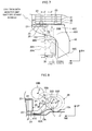
- Fig. 2 is a schematic top view of the battery pack 10 and the blower 30 disposed below the seat 102.
- Fig. 3 is a schematic side view of the battery pack and the blower viewed from the FR direction in Fig. 2 .
- An arrow RH indicates a lateral direction orthogonal to the forward direction FR of the vehicle 100.
- the battery pack 10 has an upper case 11 and a lower case 12.
- a battery stack 20 is disposed in the space surrounded by the upper case 11 and the lower case 12.
- the battery stack 20 is fixed to the upper case 11 or the lower case 12.
- the lower case 12 is fixed to the floor panel P of the vehicle 100 to fix the battery stack 20 to the floor panel P.
- the battery pack 10 may be fixed to the floor panel P through a bracket.
- the battery stack 20 corresponds to an electric storage unit of the present invention.
- the battery stack 20 has a plurality of cells 21 arranged along a predetermined direction (RH direction).
- the cell 21 corresponds to an electric storage element of the present invention.
- the plurality of cells 21 are connected electrically in serial through a bus bar.
- the battery stack 20 may include a plurality of cells 21 connected electrically in parallel.
- a so-called square-type cell is used as the cell 21 in the present embodiment.
- the square-type cell 21 is a cell having planes orthogonal to the direction along which the plurality of cells 21 are arranged.
- a secondary battery such as a nickel metal hydride battery or a lithium-ion battery can be used as the cell 21.
- An electric double layer capacitor may be used instead of the secondary battery.
- the present invention is not limited thereto.
- two or more cells can constitute a battery module, and a plurality of such battery modules can be arranged along one direction (RH direction).
- the plurality of cells contained in the single battery module can be connected electrically in serial.
- a pair of end plates 22 are disposed at both ends of the battery stack 20 in the direction (RH direction) along which the plurality of cells 21 are arranged.
- the pair of end plates 22 hold the plurality of cells 21 constituting the battery stack 20 between them and are used to apply a restraint force to the plurality of cells 21.
- the restraint force refers to a force which tightly holds the cells 21 in the RH direction.
- the restraint force applied to the cells 21 can suppress expansion of the cells 21 to prevent deterioration of input/output characteristics of the cells 21.
- both ends of a restraint band 23 extending in the RH direction are connected to the pair of end plates 22.
- the end plate 22 has a fixing portion 24 formed thereon to which the restraint band 23 is coupled.
- the end of the restraint band 23 is coupled to the fixing portion 24 to connect the restraint band 23 to the end plate 22.
- the restraint band 23 is disposed on each of an upper face and a lower face of the battery stack 20.
- the position to dispose the restraint band 23 can be set as appropriate as long as both ends of the restraint band 23 are connected to the pair of end plates 22.
- the restraint band 23 may be disposed on each of side faces of the battery stack 20 in the FR direction.
- a spacer can be disposed between adjacent two of the cells 21.
- the spacer is used to form a space between the two cells 21.
- the spacer can be made of an insulating material such as resin.
- the space formed by the spacer serves as the space through which the air for adjusting the temperature of the cell 21 moves.
- an intake passage S1 is formed on the upper face of the battery stack 20, and an exhaust passage S2 is formed on the lower face of the battery stack 20.
- the intake passage S1 is formed by the upper face of the battery stack 20 and the upper case 11.
- the exhaust passage S2 is formed by the lower face of the battery stack 20 and the lower case 12.
- a portion (hereinafter referred to as a base) 12a of the lower case 12 extends in the RH direction.
- the blower 30 is fixed to the base 12a.
- the battery pack 10 can be mounted on the vehicle 100 with the blower 30 attached to the base 12a (lower case 12).
- the battery pack 10 and the blower 30 can be handled as an integral unit and can be mounted easily on the vehicle 100.
- the base 12a of the present embodiment has a blower attaching portion 12b located at a lower face of the blower 30 disposed adjacently to a side face of the battery stack 20 in the RH direction.
- the base 12a is bent upward from a lower face of the lower case 12 to the blower attaching portion 12b such that the blower attaching portion 12b is located above the lower face of the lower case 12.
- the base 12a may be provided as a member independent of the lower case 12 and may be connected to the lower case 12, or the base 12b may be formed integrally with the lower case 12.
- the blower 30 is disposed adjacently to the side face of the battery stack 20 in the RH direction. In other words, the blower 30 is disposed adjacently in the direction along which the plurality of cells 21 of the battery stack 20 are arranged. For example as shown in Fig. 2 , the blower 30 is disposed closer to the exterior of the body of the vehicle 100 (for example, closer to a side portion of the vehicle in the RH direction) than the battery stack 20 in the present embodiment.
- An outflow port of the blower 30 is connected to an intake duct 32 through a duct 31.
- the intake duct 32 is disposed between the battery stack 10 and the blower 30 and is connected to the intake passage S1 of the battery pack 10.
- An intake duct 41 is connected to an inflow port of the blower 30.
- An intake port is provided at an end of the intake duct 41 connected to the blower 30. The intake port of the intake duct 41 is exposed to the interior of the vehicle.
- the blower 30 has a housing portion 30A having the outflow port connected to the duct 31 and the inflow port connected to the intake duct 41 formed therein, and a blower motor 30B put in the housing portion 30A.
- the blower motor 30B is a circular motor which is driven to rotate with power supplied to the blower motor 30B.
- the blower motor 30B is connected to a runner which has a plurality of blades arranged in cylindrical form and elongated in a rotation axis direction. When the blower motor 30B is driven, air in the interior of the vehicle is taken into the blower 30 through the intake duct 41 and is introduced into the intake passage S1 of the battery pack 10 through the intake duct 32.
- the blower motor 30B is disposed adjacently to the battery pack 10 such that the rotation axis direction of the blower motor 30B is generally in parallel with the FR direction of the battery pack 10.
- the blower 30 is disposed adjacently to the side face of the battery pack 10 such that the rotation axis of the blower motor 30B extends in the direction generally perpendicular to the RH direction.
- the intake duct 41 connected to the inflow port of the blower 30 is faced to a front side of the seat 102 in the FR direction.
- the blower 30B takes in the air in the interior of the vehicle from the FR direction generally in parallel with the rotation axis direction of the blower motor 30B, flows the air in the RH direction generally perpendicular to the rotation axis direction, and supplies the air taken from the interior of the vehicle to the intake duct 32 (battery pack 10).
- the air in the interior of the vehicle taken through the intake duct 41 passes through the duct 31 of the blower 30 and the intake duct 32 into the intake passage S1.
- the air moved into the intake passage S1 enters the space formed by the spacer to move from the upper face to the lower face of the battery stack 20.
- the air comes into contact with an outer face of the cell 21 to achieve heat exchange between the air and the cell 21.
- air for cooling can be brought into contact with the cell 21 to suppress a rise in temperature of the cell 21.
- air for heating can be brought into contact with the cell 21 to suppress a drop in temperature of the cell 21.
- the air in the interior of the vehicle has a temperature set appropriately for adjusting the temperature of the cell 21 by an air-conditioner or the like mounted on the vehicle 100.
- the air in the interior of the vehicle can be supplied to the cell 21 to perform the temperature adjustment for the cell 21.
- the adjustment of the temperature of the cell 21 can reduce deterioration of input/output characteristics of the cell 21.
- the air after the heat exchange with the cell 21 moves into the exhaust passage S2. Since an exhaust duct 42 is connected to the exhaust passage S2, the air moved into the exhaust passage S2 is directed to the exhaust duct 42.
- the exhaust duct 42 exhausts the air to the outside of the battery pack 10. For example, the exhaust duct 42 can let out the air to the interior of the vehicle.
- arrows indicated by solid lines represent an intake path
- arrows indicated by chain lines represent an exhaust path.
- the exhaust duct 42 can be disposed in a space S3 between the battery pack 10 and the blower 30 attached to the base 12a.
- the exhaust duct 42 is formed to have a duct portion 42A partially disposed in the space S3 between the blower 30 and the battery pack 10, and the exhaust duct 42 extends toward the back of the blower 30.
- An end of the exhaust duct 42 (outlet port of the duct portion 42A) can be connected, for example to a garnish located in the lateral direction of the vehicle 100. The air moved through the exhaust duct 42 is returned to the interior of the vehicle through the garnish.
- the exhaust duct 42 can be disposed such that the outlet port is located in the space between the luggage space or the seat 102 and a side face of the vehicle 100, for example.
- the exhaust duct 42 in the present embodiment is formed in a shape in which the duct portion 42A disposed in the space S3 guides the blower motor 30 to an upper face of the battery pack 10 when an external force is applied to the blower 30 to move the blower motor 30B toward the battery pack 10.
- the duct portion 42A can be formed to have a duct shape with its height increased in the UP direction from a connecting port 42C connected to an exhaust port of the exhaust passage S2 of the battery pack 10 toward the blower 30.
- the duct portion 42A is formed such that an upper edge Q of the duct portion 42A disposed in the space S3 is at a height (for example, a height in the UP direction relative to the floor panel P or the lower face of the battery stack 20) higher than that of the connecting port 42C located below to provide the shape inclined from the connecting portion 42C to the duct portion 42A.
- a monitor unit 51 is disposed between the battery stack 20 and the blower 30 (between the battery stack 20 and the duct portion 42A) .
- the monitor unit 51 monitors the voltage and the current of the battery stack 20.
- a plurality of voltage sensors are attached to the battery stack 20, and the result of the detection by each of the voltage sensors is output to the monitor unit 51.
- the voltage sensor can detect the voltage of each cell 21.
- the voltage sensor can detect the voltage of each of the blocks.
- Each block is formed of a plurality of cells 21.
- a current sensor is attached to the battery stack 20, and the result of the detection by the current sensor is output to the monitor unit 51.
- the information monitored by the monitor unit 51 is used to control the charge and discharge of the battery stack 20. For example, when the voltage value (detection value) of the cell 21 reaches a preset upper limit value, the charge and discharge of the battery stack 20 can be inhibited or limited.
- the limitation of the charge and discharge of the battery stack 20 can involve changing an upper limit value of power used in control of charge and discharge to a lower value.
- a relay 52 is disposed on the side of the battery stack 20 opposite to the side where the monitor unit 51 is disposed. In other words, the monitor unit 51 and the relay 52 can be disposed on both side faces of the battery stack 20 in the RH direction. While the relay 52 is ON, the charge and discharge of the battery stack 20 are allowed. While the relay 52 is OFF, the charge or discharge of the battery stack 20 are inhibited.
- a current breaker 53 is used to break a current path in the battery pack 10.
- the current breaker 53 can be formed of a plug and a grip to be inserted into the plug. The grip can be withdrawn from the plug to break the current path.
- the current breaker 53 can be disposed on the side face of the battery stack 20 on which the relay 52 is disposed.
- the monitor unit 51 can be attached to the end plate 22 for the battery stack 20.
- a protecting member 25 provides a space for housing the monitor unit 51 and is formed to have a predetermined thickness.
- the protecting member 25 protects the monitor unit 51 attached to the end plate 22 from the external force applied to the monitor unit 51.
- the protecting member 25 disposed to cover the monitor unit 51 on the side face of the end plate 22 in the RH direction is connected to the upper case 11 or the end plate 22.
- the protecting member 25 may be connected to the end plate 22 similarly to the monitor unit 51.
- the protecting member 25 has a protruding portion 26 located at the restraint band 23 connected to the end plate 22 or at the fixing portion 24 to which the restraint band 23 is coupled while the protecting member 25 is attached to the battery pack 10.
- the protruding portion 26 is disposed on a wall portion 25A forming the space for housing the monitor unit 51.
- the protruding portion 26 is disposed adjacently to the restraint band 23 in the direction along which the plurality of cell 21 are arranged.
- An end portion of the protruding portion 26 may be in contact with the restraint band 23 or the fixing portion 24, or the protruding portion 26 may be disposed flush with the restraint band 23 or the fixing portion 24 at a predetermined interval between them.
- the protruding portion 26 can be formed, for example, by protruding part of the wall portion 25A of plate shape located above the monitor unit 51 in the UP direction through squeezing.
- the protruding portion 26 serves as a reinforcement portion for the protecting member 25 against the external force applied in the RH direction.
- the protruding portion 26 comes into contact with the restraint band 23 or the fixing portion 24 to suppress deformation of the wall portion 25A.
- the protruding portion 26 prevents the space for housing the monitor unit 51 from being narrowed due to deformation of the wall portion 25A.
- the present embodiment illustrates an aspect in which the protruding portion 26 is formed integrally with the protecting member 25, the present invention is not limited thereto, and the protruding portion 26 may be formed separately and attached to the wall portion 25A.
- the protruding portion 26 may be formed to come into contact with the end plate 22 instead of the fixing portion 24 when the external force is applied.
- the protruding portion 26 may be disposed on the protecting member 25 such that the protruding portion 26 is located at the end plate 22 while it is attached to the battery pack 10.
- Fig. 4 is an external perspective view of the monitor unit 51 disposed on the battery pack 10 and the protecting member 25 for protecting the monitor unit 51.
- Fig. 5 is an external perspective view of the battery pack 10 and the exhaust duct 42.
- Fig. 6 is an external perspective view of the battery pack 10 and the blower 30.
- the monitor unit 51 can be attached to the end plate 22 of the battery stack 20.
- the protecting member 25 is attached to cover the monitor unit 51 attached to the end plate 22 in the RH direction.
- the protecting member 25 can be formed of a single plate-shaped member. Part of the wall portion (wall portion 25B) associated with the monitor unit 51 is formed in a recessed shape to provide the space for housing the monitor unit 51 between the wall portion and the end plate 22.
- the protecting member 25 of the present embodiment is formed to have a size which covers the entire outer face of the end plate 22, the protecting member 25 may be sized to cover only the monitor unit 51, for example.
- the duct portion 42A of the exhaust duct 42 is shaped to have the height increased in the UP direction from the connecting port 42C attached to the exhaust port of the exhaust passage S2 of the battery pack 10 toward the blower 30.
- the upper edge Q of the duct portion 42A is located above an upper face of the duct connecting port 42C.
- the duct portion 42A is provided with a fixing portion 42B connected to the base 12.
- the duct portion 42A is shaped to be bent in the FR direction and then extend toward the back of the blower 30 to avoid the blower 30 disposed adjacently to the battery pack 10 in the RH direction.
- an outlet port 42D of the exhaust duct 42 is disposed adjacently to the blower 30 in the FR direction.
- the present embodiment includes the duct portion 42A shaped to be inclined steeply in the UP direction from the connecting port 42C toward the blower 30, the present invention is not limited thereto.
- the duct portion 42A may have a rectangular shape or an arc shape having the upper edge Q above the connecting port 42C in the UP direction with no inclination of the upper edge Q.
- the duct portion 42A disposed in the space S3 may be shaped independently of the shape of the air flow path formed by the duct portion 42A.
- the duct portion 42A may provide the air flow path conforming to the shape protruding in the UP direction within the space S3 or provide the air flow path independently of the shape protruding in the UP direction.
- the intake duct 32 is connected to the intake passage S1 of the battery pack 10, and the exhaust duct 42 is connected to the exhaust passage S2 communicating with the intake passage S1 of the battery pack.
- the duct 31 of the blower 30 is connected to the intake duct 32, and the blower 30 is fixed to the blower attaching portion 12b of the base 12a.
- the inflow port of the blower 30 is connected to the intake duct 41.
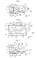
- Fig. 7 is a top view showing the positional relationship between the battery stack 20 and the adjacently disposed blower motor 30B and the movement track of the blower motor 30 when the external force is applied to the blower 30.
- the blower 30 facing the side face of the battery stack 20 in the RH direction and disposed on the base 12a may collide with the battery stack 20 (battery pack 10).
- the blower motor 30 of the blower 30 is a metallic member made of iron or the like and is harder than the housing portion 30A made of synthetic resin or the like, the external force applied to the blower 30 may cause the blower motor 30 to move toward and collide with the adjacent battery stack 20.
- the side door or the floor panel P is deformed to bring the side door closer to the blower 30. Since the blower 30 is disposed closer to the side door than the battery stack 20, the external force F may act on the blower 30 through the side door.
- An external force F1 is an external force acting on the blower 30 generally in parallel with the RH direction.
- the blower motor 30B is moved toward the battery stack 20 generally in parallel with the RH direction.
- An external force F2 is an external force acting on the blower 30 obliquely to the RH direction from the back of the vehicle 100.
- the blower motor 30B is moved toward the battery stack 20 obliquely to the RH direction.
- blower motor 30B In terms of avoiding the collision of the blower motor 30B with the battery stack 20, it is also important to prevent the blower 30 from colliding with the monitor unit 51 disposed between the blower 30 and the battery stack 20. Upon collision of the blower motor 30B with the battery stack 20, the blower motor 30B may also collide with the monitor unit 51 disposed between the blower 30 and the battery stack 20.
- the blower motor 30B when the blower motor 30B receives the external force F1 to collide with the battery pack 10 as shown in Fig. 7 , the collision with the monitor unit 51 can be avoided by offsetting the blower motor 30B from the monitor unit 51 in the FR direction.
- the blower motor 30B when the external force F2 moves the blower motor 30B obliquely to the RH direction toward the side face of the battery stack 20, the blower motor 30B may move to and collide with the monitor unit 51 even when the monitor unit 51 is offset.
- the protecting member 25 is provided for the monitor unit 51 disposed on the side face of the battery stack 20 between the battery stack 20 and the blower 30, the monitor unit 51 is protected by the protecting member 25 to some extent even when the blower motor 30B collides with the side face of the battery stack 20.
- the wall portion 25B of the protecting member 25 located between the monitor unit 51 and the blower 30 is struck on the surface with the blower motor 30B, so that an increased strength against the shock obtained by increasing the thickness of the protecting member 25 has a limited effect.
- the space for housing the monitor unit 51 may be dented to prevent the protecting member 25 from sufficiently protecting the monitor unit 51.
- the monitor unit 51 monitors the voltage and the current of the battery stack 20, and a high-voltage wire or the like may be connected thereto.
- the monitor unit 51 requires protection similarly to the battery stack 20 from the blower motor 30B moved when the external force F2 is applied.
- the exhaust duct 42 disposed in the space S3 between the side face of the battery stack 20 and the blower 30 is appropriately shaped to provide a collision avoiding portion for guiding the movement track of the blower motor 30B toward the upper face of the battery stack 20 when the blower motor 30 is moved toward the battery stack 20 upon application of the external force F1 or the external force F2.
- the outer shape of the duct portion 42A of the exhaust duct 42 disposed in the space S3 is formed to protrude in the UP direction to provide the duct portion 42A integral with the collision avoiding portion.
- the present embodiment prevents the blower motor 30 from colliding with the battery stack 20 and prevents the collision between the blower motor 30B and the monitor unit 51 disposed between the battery stack 20 and the blower 30 (duct portion 42A).
- Fig. 8 is a side view showing the movement track of the blower motor 30B when the external force F1 is applied thereto in a cross section taken along line A-A in Fig 7 .
- the upper edge Q of the duct portion 42A disposed in the space S3 is formed to protrude in the UP direction.
- the upper edge Q of the duct portion 42A is formed at the height in contact with a circumferential face of the blower motor 30 during the movement of the blower motor 30B in the RH direction toward the side face of the battery stack 20 upon application of the external force.
- the blower motor 30B When the blower motor 30B is moved in the RH direction toward the battery stack 20 upon application of the external force F1, the blower motor 30B comes into contact with the upper edge Q of the duct portion 42A and is prevented from moving generally perpendicularly to the side face of the battery stack 20. The movement of the blower motor 30B generally perpendicular to the side face of the battery stack 20 is guided toward the upper face of the battery stack 20. In this manner, the shape of the exhaust duct 42 (duct portion 42A) is appropriately formed to prevent the collision of the blower motor 30B with the battery stack 20 without requiring any additional component.
- the height of the upper edge Q of the duct portion 42A is lower than a center R (rotation axis) of the blower motor 30 by a predetermined value in the UP direction.
- the upper edge Q of the duct portion 42A is formed at the height lower than the position of the center R of the blower motor 30B in the UP direction relative to the floor panel P or the lower face of the battery stack 20 by a predetermined value H1, and the duct portion 42A and the center R of the blower motor 30B are separated from each other in the UP direction at the distance of the predetermined value H1.
- the predetermined value H1 can be a value smaller than a radius r of the blower motor 30B. With the predetermined value H1 smaller than the radius r of the blower motor 30B, the shock to the duct portion 42A upon contact with the blower motor 30B can be dispersed, and the upper edge Q of the duct portion 42A can serve as a springboard to cause the movement of the blower motor 30B generally perpendicular to the side face of the battery stack 20 to be guided toward the upper face of the battery stack 20, although the duct portion 42A has no guide face for guiding the blower motor 30B toward the upper face of the battery stack 20.
- the predetermined value H1 can be set as appropriate in view of an angle at which the blower motor 30B is moved toward the upper face of the battery stack 20 without colliding with the battery stack 20 after the contact with the upper edge Q of the duct portion 42A.
- FIG. 9 is a side view showing the positional relationship between the center R of the blower motor 30B and the exhaust duct 42 and the positional relationship between the center R of the blower motor 30B and the protecting member 25 for the monitor unit 51 in a cross section taken along line B-B in Fig. 7 .
- Fig. 9 is a side view showing the positional relationship between the center R of the blower motor 30B and the exhaust duct 42 and the positional relationship between the center R of the blower motor 30B and the protecting member 25 for the monitor unit 51 in a cross section taken along line B-B in Fig. 7 .
- FIG. 10 is a diagram showing the positional relationship between the exhaust duct 42 and the center R of the blower motor 30B on the side face of the battery stack 20 on which the monitor unit 51 is disposed when viewed from the RH direction and the positional relationship between the center R of the blower motor 30B and the protecting member 25 in which the monitor unit 51 is disposed.
- Fig. 11 is a diagram showing the movement track of the blower motor 30B when the external force F2 is applied thereto.
- the blower motor 30B offset from the monitor unit 51 rearward in the FR direction is moved obliquely to the RH direction toward the side face of the battery stack 20.
- the blower motor 30B may collide with the monitor unit 51 disposed on the outer face of the end plate 22 between the battery stack 20 and the blower 30.
- the upper edge Q of the duct portion 42 can be formed at the height in contact with the blower motor 30 during the movement of the blower motor 30B in the RH direction toward the side face of the battery stack 20 upon application of the external force.
- the upper edge Q of the duct portion 42A is shaped to have the height defined by the positional relationship with an upper end (wall portion 25A) of the monitor unit 51. If the upper edge Q of the duct portion 42 is located at a distance larger than the radius r of the blower motor 30B from the upper end in the UP direction of the monitor unit 51 disposed on the battery stack 20, the blower motor 30B moved generally perpendicularly to the side face of the battery stack 20 collides with the wall portion 25B to prevent sufficient protection of the monitor unit 51.
- the height of the upper edge Q of the duct portion 42A is defined such that the distance in the UP direction between the upper edge Q of the duct portion 42A disposed in the space S3 and the upper end of the monitor unit 51 relative to the floor panel P or the battery stack 20 has a predetermined value H2 less than the radius r of the blower motor 30B.
- the duct portion 42A is shaped such that the upper edge Q of the duct portion 42A defined in this manner is located to protrude between the battery stack 20 and the blower 30.
- the upper edge Q of the duct portion 42A can be formed at the height to protrude between the battery stack 20 and the blower 30 such that the height of the upper end of the monitor unit 51 is lower than the height provided by adding the height of the upper edge Q of the duct portion 42A to the radius r of the blower motor 30B.
- the upper edge Q of the duct portion 42A can be formed to have the height to protrude between the battery stack 20 and the blower 30 such that the height of the upper end of the monitor unit 51 is lower than the height provided by adding the height of the upper edge Q of the duct portion 42A to the radius r of the blower motor 30B. Consequently, the blower motor 30B comes into contact with the upper edge Q of the duct portion 42A to prevent the movement generally perpendicular to the monitor unit 51 (the side face of the battery stack 20). The movement of the blower motor 30B generally perpendicular to the side face of the monitor unit 51 is guided toward the upper face of the battery stack 20. As shown in Fig. 11 , the shape of the exhaust duct 42 (duct portion 42A) is appropriately formed to avoid the collision of the blower motor 30B with the wall portion 25B without requiring any additional component.
- the blower motor 30B may come into contact with the wall portion 25A of the protecting member 25 housing the monitor unit 51.
- the height of the upper edge Q of the duct portion 42A defined by the relationship with the height of the upper end of the monitor unit 51 can avoid the collision of the blower motor 30B with the wall portion 25B, but the movement of the blower motor 30B toward the upper face of the battery stack 20 may be blocked by a lower face S of the seat 102 to cause the blower motor 30B to collide with the protecting member 25, that is, the wall portion 25A disposed on the upper end of the monitor unit 51.
- the protruding portion 26 is formed on the wall portion 25A.
- the protruding portion 26 serves as the reinforcement portion against the shock to the wall portion 25A and can suppress deformation of the wall portion 25A due to the collision of the blower motor 30B to protect the monitor unit 51.
- the protruding portion 26 is provided on the wall portion 25A disposed on the upper end of the monitor unit 51 and is formed to protrude upward from the wall portion 25A by a predetermined height H3.
- the predetermined height H3 corresponds to a height from the wall portion 25A to the restraint band 23 or the fixing portion 24, and the protruding portion 26 is disposed at the restraint band 23 connected to the end plate 22 or at the fixing portion 24 to which the restraint band 23 is coupled.
- the protruding portion 26 can come into contact with the restraint band 23 or the fixing portion 24 to suppress the deformation of the wall portion 25A to prevent the space housing the monitor unit 51 from being narrowed due to the deformation of the wall portion 25A.
- the battery stack 20 can be protected from the collision of the blower motor 30B, for example by forming the end plate 22 to have a strength which can withstand the shock of the collision of the blower motor 30.
- the monitor unit 51 cannot be protected sufficiently by enhancing the strength of the protecting member 25, so that the upper edge Q of the duct portion 42A is formed at the height to protrude between the battery stack 20 and the blower 30 such that the height of the upper end of the monitor unit 51 is lower than the height provided by adding the height of the upper edge Q of the duct portion 42A to the radius r of the blower motor 30B, thereby avoiding the collision of the motor blower 30B with the wall portion 25B to protect the monitor unit 51 properly.
- the upper edge Q of the duct portion 42A is formed at the height to protrude between the battery stack 20 and the blower 30 such that the upper edge Q of the duct portion 42 is at the height lower than the center R of the blower motor 30 in the UP direction by the predetermined value less than the radius r of the blower motor 30B, and that the height of the upper end of the monitor unit 51 is lower than the height provided by adding the height of the upper edge Q of the duct portion 42A to the radius r of the blower motor 30B.
- This can prevent the collision of the blower motor 30B with the side face of the battery stack 20 and with the monitor unit 51 disposed on the side face of the battery stack 20.
- blower motor 30B when the blower 30 (blower motor 30B) is located rearward of the monitor unit 51 in the FR direction, and the angle at which the blower motor 30B is moved obliquely to the RH direction by the external force F2 is larger than an angle indicated by a chain double-dashed line in Fig. 7 , then the blower motor 30B deviates from the side face of the battery stack 20 and thus does not collide.
- the upper edge Q of the duct portion 42A is formed at the height to protrude between the battery stack 20 and the blower 30 such that the upper edge Q of the duct portion 42A is at the height lower than the center R of the blower motor 30 in the UP direction by the predetermined value less than the radius r of the blower motor 30B and/or that the height of the upper edge of the monitor unit 51 is lower than the height provided by adding the height of the upper edge Q of the duct portion 42A to the radius r of the blower motor 30B, thereby allowing the prevention of the collision of the blower motor 30B with the side face of the battery stack 20 and with the monitor unit 51 disposed on the side face of the battery stack 20.
- the upper edge Q of the duct portion 42A disposed in the area less close to the blower motor 30B and forward of the position indicated by the symbol Q1 in the FR direction relative to the monitor unit 51 may have a shape which does not satisfy the positional relationships defined by the predetermine values H1 and H2 for the center R of the blower motor 30B and the upper end of the monitor unit 51.
- the entire upper edge Q of the duct portion 42 disposed in the space S3 between the side face of the battery stack 20 and the blower 30 may have a shape which satisfies the positional relationships defined by the predetermine values H1 and H2 for the center R of the blower motor 30B and the upper end of the monitor unit 51.
- the present embodiment includes the intake passage S1 provided on the upper face side of the battery stack 20 and the exhaust passage S2 provided on the lower face side of the battery stack 20, the present invention is not limited thereto.
- the intake passage and the exhaust passage may be provided at positions between which the battery stack 20 is sandwiched.
- the exhaust passage can be provided on the upper face side of the battery stack 20 and the intake passage can be provided on the lower face side of the battery stack 20.
- the duct portion 42A of the exhaust duct 42 connected to the exhaust passage and disposed in the space S3 can guide the blower motor 30B toward the lower face of the battery stack 20 to prevent the collision between the blower motor 30B and the battery stack 20 and the collision between the blower motor 30B and the monitor unit 51 as described above.
- the present embodiment includes the collision avoiding portion provided for the exhaust duct 42 disposed between the battery stack 20 and the blower 30 (blower motor 30B), the present invention is not limited thereto.
- the collision avoiding portion may be provided for the intake duct 32.
- the intake duct 32 can be formed to have a shape similar to that of the duct portion 42A to guide the blower motor 30B toward the upper face of the battery stack 20 to prevent the collision between the blower motor 30B and the battery stack 20 (monitor unit 51).
- the present embodiment includes the monitor unit 51 disposed between the battery stack 20 and the blower 30, the present invention is not limited thereto.
- a device used to control the charge and discharge of the battery stack 20 can be disposed instead of or in addition to the monitor unit 51.
- the device include a relay 52, a voltage sensor, a current sensor, and a temperature sensor, in addition to the monitor unit 51.
- the temperature sensor is used to detect the temperature of the battery stack 20, and the result of the detection by the temperature sensor is used to control the charge and discharge of the battery stack 20. In this case, the collision of the blower motor 30B with the device disposed between the battery stack 20 and the blower 30 can also be avoided.
- the present embodiment includes the monitor unit 51 disposed at the left of the end plate 22 in Fig. 7 by way of example, the present invention is not limited thereto.
- the monitor unit 51 can be disposed at the center or at the right of the end plate 22 in the FR direction.
- the protecting member 25 forms the space for housing the monitor unit 51 in association with the position of the monitor unit 51 disposed on the end plate 22.
- FIG. 13 is an external perspective view of an exhaust duct 42 provided with ribs (guide member) 60.
- Members having the functions identical to those described in Embodiment 1 are designated with the same reference numerals, and detailed description thereof is omitted. The following description is mainly focused on differences from Embodiment 1.
- Embodiment 1 includes the duct portion 42A of the exhaust duct 42 shaped to have the height increased in the UP direction within the space S3 between the battery pack 10 and the blower 30.
- a duct portion 42A is formed to have an upper end face of flat shape (as a plane), and a plurality of ribs 60 protruding in the UP direction and having guide faces 61 are formed on the upper end face of the duct portion 42A.
- the ribs 60 guide a blower motor 30 toward an upper face or a lower face of a battery stack 20 when the blower motor 30B is moved by an external force F1 or an external force F2 applied thereto.
- the ribs 60 are disposed between a side face of the battery stack 20 and a blower 30.
- the rib 60 is formed in a trapezoidal shape extending from the upper end face of the duct portion 42A toward the upper face of the battery stack 20.
- the guide faces 61 are opposite to the blower 30 disposed adjacently to the battery stack 20 in the RH direction and is inclined toward the side face of the battery stack 20.
- the guide face 61 inclined from the lower face toward the upper face of the battery stack 20 guides the blower motor 30B toward the upper face of the battery stack 20 when the blower motor 30B is moved toward the side face of the battery stack 20 upon application of the external force.
- the plurality of ribs 60 are arranged at predetermined intervals along the FR direction of the battery stack 20 such that the guide faces 61 face the blower 30.
- the plurality of ribs 60 may be formed of a single rib.
- the rib having the guide face 61 wide in the FR direction of the battery stack 20 may be disposed.
- the inclination angle of the guide face 61 can be an arbitrary angle at which the blower motor 30B can be guided toward the upper face of the battery stack 20 after the blower motor 30B hits the guide face 61.
- the blower motor 30B is moved toward the side face of the battery stack 20 and comes into contact with the guide faces 61 of the ribs 60 disposed between the battery stack 20 and the blower 30.
- the blower motor 30B moved generally perpendicularly to the side face of the battery stack 20 is guided toward the upper face of the battery stack 20 by the guide faces 61.
- a monitor unit 51 and a protecting member 25 can be disposed on the side face of the battery stack 20, and in this case, the ribs 60 are disposed closer to the blower 30 than the monitor unit 51.
- the rib 60 disposed between the battery stack 20 and the blower 30 and formed on the duct portion 42A of the exhaust duct 42 is provided as the collision avoiding portion in Embodiment 1 and can prevent the collision of the blower motor 30B with the battery stack 20 and the monitor unit 51 upon application of the external force.
- the present embodiment includes the ribs 60 provided for the overall side face of the battery stack 20, the present invention is not limited thereto.
- an end plate 22 can be formed to have a strength which can withstand the shock of the collision of the blower motor 30B with the side face of the battery stack 20 to protect the battery stack 20 from the collision of the blower motor 30B without providing the ribs 60.
- the ribs 60 can be disposed to avoid the collision of the blower motor 30B with the monitor unit 51.
- the guide face 61 of the rib 60 may be provided as a guide face for guiding the blower motor 30B toward the lower face of the battery stack 20 when the motor 30B is moved toward the side face of the battery stack 20 upon application the external force.
- the rib 60 having the guide face 61 inclined toward the blower 30 can be disposed on the exhaust duct 42 or an intake duct 32, so that the blower motor 30B can be guided toward the lower face of the battery stack 20 through the guide face 61.
- FIG. 15 is an external perspective view of an exhaust duct 42 provided with a rib 70 (guide member).
- Members having the functions identical to those described in Embodiment 1 are designated with the same reference numerals, and detailed description thereof is omitted. The following description is mainly focused on differences from Embodiment 1.
- the duct portion 42A of the exhaust duct 42 is shaped to have the height increased in the UP direction within the space S3 between the battery pack 10 and the blower 30, and the exhaust duct 42 is provided with the ribs 60 having the guide faces 60, so that the blower motor 30 moved by the external force F1 or F2 is guided toward the upper face or the lower face of the battery stack 20.
- the rib 70 guides a blower motor 30B in the FR direction (toward a side face of a battery stack 20 in the FR direction) instead of the up-down direction of the battery stack 20, thereby preventing the collision with the battery stack 20 or a monitor unit 51.
- a duct portion 42A is formed to have an upper end face of flat shape (as a plane) similarly to Embodiment 2, and the rib 70 is formed on the upper end face of the duct portion 42A.
- the rib 70 is disposed between a side face of the battery stack 20 and a blower 30.
- the rib 70 is a plate-shaped member inclined from a bent portion 71 extending in the UP direction toward the battery stack 20, and is formed of two plate-shaped ribs 70A and 70B extending generally vertically (UP direction) from the upper end face of the duct portion 42A. Both sides of the bent portion 71 of the rib 70 correspond to the plate-shaped ribs 70A and 70B.
- the rib 70 is formed as a wall portion which covers the side face of the battery stack 20 from the blower 30.
- the plate-shaped rib 70A faces the blower 30 and faces toward the front in the FR direction, and is inclined from the bent portion 71 toward the side face of the battery stack 20 facing the blower 30.
- the plate-shaped rib 70B faces the blower 30 and faces toward the back in the FR direction, and is inclined from the bent portion 71 toward the side face of the battery stack 20 facing the blower 30.
- Each of the inclination angles of the plate-shaped ribs 70A and 70B can be an arbitrary angle at which the blower motor 30B can be guided toward the side face of the battery stack 20 in the FR direction after the blower motor 30B collides.
- the blower motor 30B moved generally perpendicularly to the side face of the battery stack 20 facing the blower 30 is guided toward the back of the battery stack 20 in the FR direction by the plate-shaped rib 70B.
- a monitor unit 51 and a protecting member 25 can be disposed on the side face of the battery stack 20 facing the blower 30, and in this case, the rib 70 is disposed closer to the blower 30 than the monitor unit 51.
- the rib 70 disposed between the battery stack 20 and the blower 30 and formed on the duct portion 42A of the exhaust duct 42 is provided as the collision avoiding portion in Embodiment 1 and can prevent the collision of the blower motor 30B with the battery stack 20 and the monitor unit 51 upon application of the external force.
- the present embodiment includes the rib 70 provided for the overall side face of the battery stack 20 opposite to the blower 30, the present invention is not limited thereto.
- an end plate 22 can be formed to have a strength which can withstand the shock of the collision of the blower motor 30B with the side face of the battery stack 20 to protect the battery stack 20 from the collision of the blower motor 30B without providing the rib 70.
- the rib 70 can be disposed to avoid the collision of the blower motor 30B with the monitor unit 51.
- Embodiments 1 to 3 are described in conjunction with the use of the so-called square-type cell 21, the present invention is not limited thereto.
- the configuration of an assembled battery disposed adjacently to the blower 30 can be selected as appropriate.
- the assembled battery (corresponding to the electric storage unit) including so-called cylinder-type cells can be used instead of the battery stack 20 .
- the cylinder-type cell is a cell having a circular cross section orthogonal to a longitudinal direction.
- a cell covered with a laminated film can be used as the cell 21.
- the cell of the laminated type a plurality of such cells can be stacked to constitute the assembled battery (corresponding to the electric storage unit).
- Embodiments 2 and 3 are described with the example in which the upper end face of the duct portion 42A is formed in the flat shape (as the plane), the present invention is not limited thereto.
- the upper end face of the duct portion 42A may have an inclined shape or a bumpy shape.
- each of the rib 60 and the rib 70 can be disposed to conform to the shape of the upper end face of the duct portion 42A.
Landscapes
- Engineering & Computer Science (AREA)
- Chemical & Material Sciences (AREA)
- Transportation (AREA)
- Mechanical Engineering (AREA)
- Power Engineering (AREA)
- Chemical Kinetics & Catalysis (AREA)
- General Chemical & Material Sciences (AREA)
- Electrochemistry (AREA)
- Sustainable Development (AREA)
- Life Sciences & Earth Sciences (AREA)
- Sustainable Energy (AREA)
- Manufacturing & Machinery (AREA)
- Combustion & Propulsion (AREA)
- Aviation & Aerospace Engineering (AREA)
- Arrangement Or Mounting Of Propulsion Units For Vehicles (AREA)
- Secondary Cells (AREA)
- Battery Mounting, Suspending (AREA)
- Cooling, Air Intake And Gas Exhaust, And Fuel Tank Arrangements In Propulsion Units (AREA)
Abstract
Description
- The present invention relates to a vehicle which is mounted with an electric storage unit for outputting an energy for use in running of the vehicle and a blower for supplying the electric storage unit with air for temperature adjustment.
- It is known that a rise in temperature of a battery deteriorates input/output characteristics of the battery. To avoid this, a battery mounted on a hybrid car or an electric car to supply power for running of such a vehicle is cooled by air for temperature adjustment. The air for temperature adjustment can be directed to the battery through an intake duct by driving a blower, for example. The blower may be disposed adjacently to the battery.
- When an external force is applied to the blower disposed adjacently to the battery, the blower, particularly a blower motor, may collide with the battery. When a monitor unit for the battery is disposed between the battery and the blower, the blower motor may collide with the monitor unit.
-
- [Patent Document 1] Japanese Patent Laid-Open No.
2004-288527 - [Patent Document 2] Japanese Patent Laid-Open No.
2006-224874 - [Patent Document 3] Japanese Patent Laid-Open No.
2002-186101 - [Patent Document 4] Japanese Patent Laid-Open No.
2004-262412 - [Patent Document 5] Japanese Patent Laid-Open No.
2003-346759 - [Patent Document 6] Japanese Patent Laid-Open No.
2008-260382 - It is thus an object of the present invention to provide a technique capable of preventing a blower motor from colliding with a battery when an external force is applied to a blower disposed adjacently to the battery.
- It is another object of the present invention to provide a technique capable of preventing a blower motor from colliding with a monitor unit for a battery disposed between the battery and an adjacent blower when an external force is applied to the blower.
- According to an aspect, the present invention provides a vehicle including an electric storage unit having a plurality of electric storage elements and outputting an energy for use in running of the vehicle, a blower disposed closer to the exterior of the body of the vehicle than the electric storage unit and supplying the electric storage unit with air for adjusting the temperature of the electric storage element, and a duct disposed between the electric storage unit and the blower and connected to the electric storage unit or the blower. The blower includes a blower motor forming a flow of the air to be supplied to the electric storage unit, and the duct has a collision avoiding portion guiding the blower motor in an up-down direction or a side direction of the electric storage unit when the blower motor is moved toward the electric storage unit upon application of an external force.
- The collision avoiding portion has an upper end coming into contact with the blower motor when the blower motor is moved toward the electric storage unit upon application of the external force, and the upper end is formed to have a height lower than the center of the blower motor by a predetermined value. The predetermined value can be a value smaller than a radius of the blower motor.
- The vehicle further includes a device disposed between the electric storage unit and the duct and used in controlling charge and discharge of the electric storage unit. The collision avoiding portion has an upper end coming into contact with the blower motor when the blower motor is moved toward the electric storage unit upon application of the external force, and the upper end is formed to have a height at which the distance between the upper end and an upper end of the device located above the upper end of the collision avoiding portion is less than the radius of the blower motor.
- The electric storage unit can include a pair of end plates between which the plurality of electric storage elements arranged along a predetermined direction are sandwiched in the predetermined direction, and can further include a coupling member extending in the predetermined direction and having both ends connected to the pair of end plates. The vehicle further includes a protecting member protecting the device disposed on one of the end plates opposite to the blower. The protecting member has a protruding portion disposed on a wall portion opposite to the upper end of the device, the protruding portion being adjacent to the coupling member in the predetermined direction.
- The collision avoiding portion is provided integrally with the duct by forming the duct in an outer shape protruding into a space between the electric storage unit and the blower.
- The collision avoiding portion is a rib formed on the duct.
- The vehicle further includes a case forming a flow path of the air on the periphery of the electric storage unit. The duct is an exhaust duct connected to an exhaust port of the flow path.
- The plurality of electric storage elements are arranged along a predetermined direction, and the electric storage unit and the blower are arranged along the predetermined direction.
- The electric storage unit is disposed in a space formed below a seat cushion.
- According to the present invention, since the blower motor moved toward the electric storage unit upon application of the external force is guided in the up-down direction or the side direction of the electric storage unit by the duct disposed between the electric storage unit and the blower, the collision of the blower motor moved upon application of the external force with the electric storage unit can be prevented.
-
- [
Fig. 1 ] A schematic diagram of a vehicle which is Embodiment 1. - [
Fig. 2 ] A schematic top view of a battery pack and a blower in Embodiment 1. - [
Fig. 3 ] A schematic side view of the battery pack and the blower in Embodiment 1. - [
Fig. 4 ] An external perspective view of a monitor unit disposed on the battery pack and a protecting member for the monitor unit in Embodiment 1. - [
Fig. 5 ] An external perspective view of the battery pack and an exhaust duct in Embodiment 1. - [
Fig. 6 ] An external perspective view of the battery pack and a blower in Embodiment 1. - [
Fig. 7 ] A top view showing the positional relationship between the battery pack and an adjacently disposed blower motor and the movement track of the blower when an external force is applied thereto in Embodiment 1. - [
Fig. 8 ] A side view showing the movement track of the blower when an external force F1 is applied thereto in a cross section taken along line A-A inFig 7 . - [
Fig. 9 ] A side view showing the positional relationship between the center of the blower motor and the exhaust duct and the positional relationship between the center of the blower motor and the protecting member for the monitor unit in a cross section taken along line B-B inFig. 7 . - [
Fig. 10 ] A side view showing the positional relationship between the center of the blower motor and the exhaust duct and the positional relationship between the center of the blower motor and the protecting member for the monitor unit. - [
Fig. 11 ] A side view showing the movement track of the blower when an external force F2 is applied thereto inFig. 9 . - [
Fig. 12 ] A schematic side view showing a variation of the exhaust duct in Embodiment 1. - [
Fig. 13 ] An external perspective view of an exhaust duct provided with ribs (guide member) in Embodiment 2. - [
Fig. 14 ] A side view showing the movement track of a blower when an external force is applied thereto in Embodiment 2. - [
Fig. 15 ] An external perspective view of an exhaust duct provided with a rib (guide member) in Embodiment 3. - [
Fig. 16 ] A top view showing the movement track of a blower when an external force is applied thereto in Embodiment 3. - Preferred embodiments of the present invention will hereinafter be described.
-
Fig. 1 to Fig. 11 show Embodiment 1 of the present invention.Fig. 1 is a side view schematically showing a vehicle. InFig. 1 , an arrow FR indicates a forward direction of the vehicle, and an arrow UP indicates an upward direction of the vehicle. - A
vehicle 100 hasseats seat 101 is a driver's seat or a passenger's seat, for example. Theseat 102 is a rear seat. Theseats vehicle 100. Abattery pack 10 is disposed in the space formed below theseat 102 and is fixed to the floor panel. In other words, thebattery pack 10 is disposed between a seat cushion of theseat 102 and the floor panel. - Although the
battery pack 10 is disposed below theseat 102 in the present embodiment, thebattery pack 10 may be disposed in a different space within thevehicle 100. For example, thebattery pack 10 may be disposed below theseat 101 or thebattery pack 10 may be disposed in a luggage space located at the back of theseat 102. - The
battery pack 10 outputs an energy for use in running of thevehicle 100. Examples of thevehicle 100 include a hybrid car and an electric car. The hybrid car includes, as the power source for running of thevehicle 100, thebattery pack 10 and another power source such as a fuel cell and an internal-combustion engine. The electric car includes only thebattery pack 10 as the power source for thevehicle 100. - The
battery pack 10 is connected to a motor generator. The motor generator can receive the power from thebattery pack 10 to generate a kinetic energy for running of thevehicle 100. The motor generator is connected to wheels, and the kinetic energy generated by the motor generator is transferred to the wheels. For decelerating or stopping thevehicle 100, the motor generator converts a kinetic energy produced in braking of the vehicle into an electric energy. The electric energy generated by the motor generator can be stored in thebattery pack 10. - A DC/DC converter and an inverter can be placed on a current path between the
battery pack 10 and the motor generator. The DC/DC converter can be used to increase the voltage output from thebattery pack 10 and supply the increased voltage to the motor generator and to reduce the voltage output from the motor generator and supply the reduced voltage to thebattery pack 10. The inverter can be used to convert the DC power output from thebattery pack 10 into an AC power, so that an AC motor can be used as the motor generator. - Next, description is made of the
battery pack 10 mounted on thevehicle 100 and a mechanism for supplying air for temperature adjustment to thebattery pack 10 by using ablower 30.Fig. 2 is a schematic top view of thebattery pack 10 and theblower 30 disposed below theseat 102.Fig. 3 is a schematic side view of the battery pack and the blower viewed from the FR direction inFig. 2 . An arrow RH indicates a lateral direction orthogonal to the forward direction FR of thevehicle 100. - The
battery pack 10 has anupper case 11 and alower case 12. Abattery stack 20 is disposed in the space surrounded by theupper case 11 and thelower case 12. Thebattery stack 20 is fixed to theupper case 11 or thelower case 12. Thelower case 12 is fixed to the floor panel P of thevehicle 100 to fix thebattery stack 20 to the floor panel P. Thebattery pack 10 may be fixed to the floor panel P through a bracket. - The
battery stack 20 corresponds to an electric storage unit of the present invention. Thebattery stack 20 has a plurality ofcells 21 arranged along a predetermined direction (RH direction). Thecell 21 corresponds to an electric storage element of the present invention. The plurality ofcells 21 are connected electrically in serial through a bus bar. Thebattery stack 20 may include a plurality ofcells 21 connected electrically in parallel. - A so-called square-type cell is used as the
cell 21 in the present embodiment. The square-type cell 21 is a cell having planes orthogonal to the direction along which the plurality ofcells 21 are arranged. A secondary battery such as a nickel metal hydride battery or a lithium-ion battery can be used as thecell 21. An electric double layer capacitor may be used instead of the secondary battery. - Although the plurality of
cells 21 are arranged along one direction in the present embodiment, the present invention is not limited thereto. Specifically, two or more cells can constitute a battery module, and a plurality of such battery modules can be arranged along one direction (RH direction). The plurality of cells contained in the single battery module can be connected electrically in serial. - A pair of
end plates 22 are disposed at both ends of thebattery stack 20 in the direction (RH direction) along which the plurality ofcells 21 are arranged. The pair ofend plates 22 hold the plurality ofcells 21 constituting thebattery stack 20 between them and are used to apply a restraint force to the plurality ofcells 21. The restraint force refers to a force which tightly holds thecells 21 in the RH direction. The restraint force applied to thecells 21 can suppress expansion of thecells 21 to prevent deterioration of input/output characteristics of thecells 21. - Specifically, both ends of a
restraint band 23 extending in the RH direction are connected to the pair ofend plates 22. Theend plate 22 has a fixingportion 24 formed thereon to which therestraint band 23 is coupled. The end of therestraint band 23 is coupled to the fixingportion 24 to connect therestraint band 23 to theend plate 22. - This allows the pair of
end plates 22 to apply the restraint force to the plurality ofcells 21. Therestraint band 23 is disposed on each of an upper face and a lower face of thebattery stack 20. The position to dispose therestraint band 23 can be set as appropriate as long as both ends of therestraint band 23 are connected to the pair ofend plates 22. For example, therestraint band 23 may be disposed on each of side faces of thebattery stack 20 in the FR direction. - A spacer, not shown, can be disposed between adjacent two of the
cells 21. The spacer is used to form a space between the twocells 21. The spacer can be made of an insulating material such as resin. The space formed by the spacer serves as the space through which the air for adjusting the temperature of thecell 21 moves. - In the present embodiment, an intake passage S1 is formed on the upper face of the
battery stack 20, and an exhaust passage S2 is formed on the lower face of thebattery stack 20. The intake passage S1 is formed by the upper face of thebattery stack 20 and theupper case 11. The exhaust passage S2 is formed by the lower face of thebattery stack 20 and thelower case 12. - A portion (hereinafter referred to as a base) 12a of the
lower case 12 extends in the RH direction. Theblower 30 is fixed to thebase 12a. Thus, thebattery pack 10 can be mounted on thevehicle 100 with theblower 30 attached to thebase 12a (lower case 12). In other words, thebattery pack 10 and theblower 30 can be handled as an integral unit and can be mounted easily on thevehicle 100. - The
base 12a of the present embodiment has ablower attaching portion 12b located at a lower face of theblower 30 disposed adjacently to a side face of thebattery stack 20 in the RH direction. Thebase 12a is bent upward from a lower face of thelower case 12 to theblower attaching portion 12b such that theblower attaching portion 12b is located above the lower face of thelower case 12. Thebase 12a may be provided as a member independent of thelower case 12 and may be connected to thelower case 12, or thebase 12b may be formed integrally with thelower case 12. - The
blower 30 is disposed adjacently to the side face of thebattery stack 20 in the RH direction. In other words, theblower 30 is disposed adjacently in the direction along which the plurality ofcells 21 of thebattery stack 20 are arranged. For example as shown inFig. 2 , theblower 30 is disposed closer to the exterior of the body of the vehicle 100 (for example, closer to a side portion of the vehicle in the RH direction) than thebattery stack 20 in the present embodiment. - An outflow port of the
blower 30 is connected to anintake duct 32 through aduct 31. Theintake duct 32 is disposed between thebattery stack 10 and theblower 30 and is connected to the intake passage S1 of thebattery pack 10. Anintake duct 41 is connected to an inflow port of theblower 30. An intake port is provided at an end of theintake duct 41 connected to theblower 30. The intake port of theintake duct 41 is exposed to the interior of the vehicle. - The
blower 30 has ahousing portion 30A having the outflow port connected to theduct 31 and the inflow port connected to theintake duct 41 formed therein, and ablower motor 30B put in thehousing portion 30A. Theblower motor 30B is a circular motor which is driven to rotate with power supplied to theblower motor 30B. Theblower motor 30B is connected to a runner which has a plurality of blades arranged in cylindrical form and elongated in a rotation axis direction. When theblower motor 30B is driven, air in the interior of the vehicle is taken into theblower 30 through theintake duct 41 and is introduced into the intake passage S1 of thebattery pack 10 through theintake duct 32. - The
blower motor 30B is disposed adjacently to thebattery pack 10 such that the rotation axis direction of theblower motor 30B is generally in parallel with the FR direction of thebattery pack 10. Specifically, theblower 30 is disposed adjacently to the side face of thebattery pack 10 such that the rotation axis of theblower motor 30B extends in the direction generally perpendicular to the RH direction. In the present embodiment, as shown inFig. 2 , theintake duct 41 connected to the inflow port of theblower 30 is faced to a front side of theseat 102 in the FR direction. Theblower 30B takes in the air in the interior of the vehicle from the FR direction generally in parallel with the rotation axis direction of theblower motor 30B, flows the air in the RH direction generally perpendicular to the rotation axis direction, and supplies the air taken from the interior of the vehicle to the intake duct 32 (battery pack 10). - The air in the interior of the vehicle taken through the
intake duct 41 passes through theduct 31 of theblower 30 and theintake duct 32 into the intake passage S1. The air moved into the intake passage S1 enters the space formed by the spacer to move from the upper face to the lower face of thebattery stack 20. - The air comes into contact with an outer face of the
cell 21 to achieve heat exchange between the air and thecell 21. For example, when thecell 21 generates heat due to charge or discharge, air for cooling can be brought into contact with thecell 21 to suppress a rise in temperature of thecell 21. When thecell 21 is extremely cooled, air for heating can be brought into contact with thecell 21 to suppress a drop in temperature of thecell 21. - The air in the interior of the vehicle has a temperature set appropriately for adjusting the temperature of the
cell 21 by an air-conditioner or the like mounted on thevehicle 100. Thus, the air in the interior of the vehicle can be supplied to thecell 21 to perform the temperature adjustment for thecell 21. The adjustment of the temperature of thecell 21 can reduce deterioration of input/output characteristics of thecell 21. - The air after the heat exchange with the
cell 21 moves into the exhaust passage S2. Since anexhaust duct 42 is connected to the exhaust passage S2, the air moved into the exhaust passage S2 is directed to theexhaust duct 42. Theexhaust duct 42 exhausts the air to the outside of thebattery pack 10. For example, theexhaust duct 42 can let out the air to the interior of the vehicle. InFig. 2 , arrows indicated by solid lines represent an intake path, and arrows indicated by chain lines represent an exhaust path. - The
exhaust duct 42 can be disposed in a space S3 between thebattery pack 10 and theblower 30 attached to thebase 12a. For example, theexhaust duct 42 is formed to have aduct portion 42A partially disposed in the space S3 between theblower 30 and thebattery pack 10, and theexhaust duct 42 extends toward the back of theblower 30. An end of the exhaust duct 42 (outlet port of theduct portion 42A) can be connected, for example to a garnish located in the lateral direction of thevehicle 100. The air moved through theexhaust duct 42 is returned to the interior of the vehicle through the garnish. Theexhaust duct 42 can be disposed such that the outlet port is located in the space between the luggage space or theseat 102 and a side face of thevehicle 100, for example. - The
exhaust duct 42 in the present embodiment is formed in a shape in which theduct portion 42A disposed in the space S3 guides theblower motor 30 to an upper face of thebattery pack 10 when an external force is applied to theblower 30 to move theblower motor 30B toward thebattery pack 10. - For example, the
duct portion 42A can be formed to have a duct shape with its height increased in the UP direction from a connectingport 42C connected to an exhaust port of the exhaust passage S2 of thebattery pack 10 toward theblower 30. Specifically, theduct portion 42A is formed such that an upper edge Q of theduct portion 42A disposed in the space S3 is at a height (for example, a height in the UP direction relative to the floor panel P or the lower face of the battery stack 20) higher than that of the connectingport 42C located below to provide the shape inclined from the connectingportion 42C to theduct portion 42A. - A
monitor unit 51 is disposed between thebattery stack 20 and the blower 30 (between thebattery stack 20 and theduct portion 42A) . Themonitor unit 51 monitors the voltage and the current of thebattery stack 20. Specifically, a plurality of voltage sensors are attached to thebattery stack 20, and the result of the detection by each of the voltage sensors is output to themonitor unit 51. The voltage sensor can detect the voltage of eachcell 21. When the plurality ofcells 21 constituting thebattery stack 20 are divided into a plurality of blocks, the voltage sensor can detect the voltage of each of the blocks. Each block is formed of a plurality ofcells 21. A current sensor is attached to thebattery stack 20, and the result of the detection by the current sensor is output to themonitor unit 51. - The information monitored by the
monitor unit 51 is used to control the charge and discharge of thebattery stack 20. For example, when the voltage value (detection value) of thecell 21 reaches a preset upper limit value, the charge and discharge of thebattery stack 20 can be inhibited or limited. The limitation of the charge and discharge of thebattery stack 20 can involve changing an upper limit value of power used in control of charge and discharge to a lower value. - A
relay 52 is disposed on the side of thebattery stack 20 opposite to the side where themonitor unit 51 is disposed. In other words, themonitor unit 51 and therelay 52 can be disposed on both side faces of thebattery stack 20 in the RH direction. While therelay 52 is ON, the charge and discharge of thebattery stack 20 are allowed. While therelay 52 is OFF, the charge or discharge of thebattery stack 20 are inhibited. - A
current breaker 53 is used to break a current path in thebattery pack 10. Thecurrent breaker 53 can be formed of a plug and a grip to be inserted into the plug. The grip can be withdrawn from the plug to break the current path. Thecurrent breaker 53 can be disposed on the side face of thebattery stack 20 on which therelay 52 is disposed. - The
monitor unit 51 can be attached to theend plate 22 for thebattery stack 20. A protectingmember 25 provides a space for housing themonitor unit 51 and is formed to have a predetermined thickness. The protectingmember 25 protects themonitor unit 51 attached to theend plate 22 from the external force applied to themonitor unit 51. The protectingmember 25 disposed to cover themonitor unit 51 on the side face of theend plate 22 in the RH direction is connected to theupper case 11 or theend plate 22. The protectingmember 25 may be connected to theend plate 22 similarly to themonitor unit 51. - The protecting
member 25 has a protrudingportion 26 located at therestraint band 23 connected to theend plate 22 or at the fixingportion 24 to which therestraint band 23 is coupled while the protectingmember 25 is attached to thebattery pack 10. The protrudingportion 26 is disposed on awall portion 25A forming the space for housing themonitor unit 51. The protrudingportion 26 is disposed adjacently to therestraint band 23 in the direction along which the plurality ofcell 21 are arranged. An end portion of the protrudingportion 26 may be in contact with therestraint band 23 or the fixingportion 24, or the protrudingportion 26 may be disposed flush with therestraint band 23 or the fixingportion 24 at a predetermined interval between them. - The protruding
portion 26 can be formed, for example, by protruding part of thewall portion 25A of plate shape located above themonitor unit 51 in the UP direction through squeezing. The protrudingportion 26 serves as a reinforcement portion for the protectingmember 25 against the external force applied in the RH direction. For example, when thewall portion 25A receives the external force in the RH direction, the protrudingportion 26 comes into contact with therestraint band 23 or the fixingportion 24 to suppress deformation of thewall portion 25A. The protrudingportion 26 prevents the space for housing themonitor unit 51 from being narrowed due to deformation of thewall portion 25A. - Although the present embodiment illustrates an aspect in which the protruding
portion 26 is formed integrally with the protectingmember 25, the present invention is not limited thereto, and the protrudingportion 26 may be formed separately and attached to thewall portion 25A. The protrudingportion 26 may be formed to come into contact with theend plate 22 instead of the fixingportion 24 when the external force is applied. In other words, the protrudingportion 26 may be disposed on the protectingmember 25 such that the protrudingportion 26 is located at theend plate 22 while it is attached to thebattery pack 10. -
Fig. 4 is an external perspective view of themonitor unit 51 disposed on thebattery pack 10 and the protectingmember 25 for protecting themonitor unit 51.Fig. 5 is an external perspective view of thebattery pack 10 and theexhaust duct 42.Fig. 6 is an external perspective view of thebattery pack 10 and theblower 30. - As shown in
Fig. 4 , themonitor unit 51 can be attached to theend plate 22 of thebattery stack 20. The protectingmember 25 is attached to cover themonitor unit 51 attached to theend plate 22 in the RH direction. The protectingmember 25 can be formed of a single plate-shaped member. Part of the wall portion (wall portion 25B) associated with themonitor unit 51 is formed in a recessed shape to provide the space for housing themonitor unit 51 between the wall portion and theend plate 22. Although the protectingmember 25 of the present embodiment is formed to have a size which covers the entire outer face of theend plate 22, the protectingmember 25 may be sized to cover only themonitor unit 51, for example. - As shown in
Fig. 5 , theduct portion 42A of theexhaust duct 42 is shaped to have the height increased in the UP direction from the connectingport 42C attached to the exhaust port of the exhaust passage S2 of thebattery pack 10 toward theblower 30. The upper edge Q of theduct portion 42A is located above an upper face of theduct connecting port 42C. Theduct portion 42A is provided with a fixingportion 42B connected to thebase 12. Theduct portion 42A is shaped to be bent in the FR direction and then extend toward the back of theblower 30 to avoid theblower 30 disposed adjacently to thebattery pack 10 in the RH direction. For example, when viewed from the top of thebattery pack 10, anoutlet port 42D of theexhaust duct 42 is disposed adjacently to theblower 30 in the FR direction. - Although the present embodiment includes the
duct portion 42A shaped to be inclined steeply in the UP direction from the connectingport 42C toward theblower 30, the present invention is not limited thereto. For example, theduct portion 42A may have a rectangular shape or an arc shape having the upper edge Q above the connectingport 42C in the UP direction with no inclination of the upper edge Q. In addition, theduct portion 42A disposed in the space S3 may be shaped independently of the shape of the air flow path formed by theduct portion 42A. Thus, theduct portion 42A may provide the air flow path conforming to the shape protruding in the UP direction within the space S3 or provide the air flow path independently of the shape protruding in the UP direction. - As shown in
Fig. 6 , theintake duct 32 is connected to the intake passage S1 of thebattery pack 10, and theexhaust duct 42 is connected to the exhaust passage S2 communicating with the intake passage S1 of the battery pack. Theduct 31 of theblower 30 is connected to theintake duct 32, and theblower 30 is fixed to theblower attaching portion 12b of thebase 12a. The inflow port of theblower 30 is connected to theintake duct 41. - Next, description is made of the specific structures of the
exhaust duct 42 disposed between thebattery stack 20 and theblower 30 and of theblower 30.Fig. 7 is a top view showing the positional relationship between thebattery stack 20 and the adjacently disposedblower motor 30B and the movement track of theblower motor 30 when the external force is applied to theblower 30. - As shown in
Fig. 7 , when the external force (the force acting in a left-right direction of the vehicle 100) is applied to theblower 30, theblower 30 facing the side face of thebattery stack 20 in the RH direction and disposed on thebase 12a may collide with the battery stack 20 (battery pack 10). Particularly, since theblower motor 30 of theblower 30 is a metallic member made of iron or the like and is harder than thehousing portion 30A made of synthetic resin or the like, the external force applied to theblower 30 may cause theblower motor 30 to move toward and collide with theadjacent battery stack 20. - For example, when an external force F is applied to a side door of the
vehicle 100, the side door or the floor panel P is deformed to bring the side door closer to theblower 30. Since theblower 30 is disposed closer to the side door than thebattery stack 20, the external force F may act on theblower 30 through the side door. - An external force F1 is an external force acting on the
blower 30 generally in parallel with the RH direction. When the external force F1 is applied to theblower 30, theblower motor 30B is moved toward thebattery stack 20 generally in parallel with the RH direction. An external force F2 is an external force acting on theblower 30 obliquely to the RH direction from the back of thevehicle 100. When the external force F2 is applied to theblower 30, theblower motor 30B is moved toward thebattery stack 20 obliquely to the RH direction. - In terms of avoiding the collision of the
blower motor 30B with thebattery stack 20, it is also important to prevent theblower 30 from colliding with themonitor unit 51 disposed between theblower 30 and thebattery stack 20. Upon collision of theblower motor 30B with thebattery stack 20, theblower motor 30B may also collide with themonitor unit 51 disposed between theblower 30 and thebattery stack 20. - For example, when the
blower motor 30B receives the external force F1 to collide with thebattery pack 10 as shown inFig. 7 , the collision with themonitor unit 51 can be avoided by offsetting theblower motor 30B from themonitor unit 51 in the FR direction. However, when the external force F2 moves theblower motor 30B obliquely to the RH direction toward the side face of thebattery stack 20, theblower motor 30B may move to and collide with themonitor unit 51 even when themonitor unit 51 is offset. - Since the protecting
member 25 is provided for themonitor unit 51 disposed on the side face of thebattery stack 20 between thebattery stack 20 and theblower 30, themonitor unit 51 is protected by the protectingmember 25 to some extent even when theblower motor 30B collides with the side face of thebattery stack 20. However, thewall portion 25B of the protectingmember 25 located between themonitor unit 51 and theblower 30 is struck on the surface with theblower motor 30B, so that an increased strength against the shock obtained by increasing the thickness of the protectingmember 25 has a limited effect. Thus, when theblower motor 30B collides with the protectingmember 25, the space for housing themonitor unit 51 may be dented to prevent the protectingmember 25 from sufficiently protecting themonitor unit 51. - As described above, the
monitor unit 51 monitors the voltage and the current of thebattery stack 20, and a high-voltage wire or the like may be connected thereto. Themonitor unit 51 requires protection similarly to thebattery stack 20 from theblower motor 30B moved when the external force F2 is applied. - To achieve this, in the present embodiment, the
exhaust duct 42 disposed in the space S3 between the side face of thebattery stack 20 and theblower 30 is appropriately shaped to provide a collision avoiding portion for guiding the movement track of theblower motor 30B toward the upper face of thebattery stack 20 when theblower motor 30 is moved toward thebattery stack 20 upon application of the external force F1 or the external force F2. In the present embodiment, the outer shape of theduct portion 42A of theexhaust duct 42 disposed in the space S3 is formed to protrude in the UP direction to provide theduct portion 42A integral with the collision avoiding portion. - The present embodiment prevents the
blower motor 30 from colliding with thebattery stack 20 and prevents the collision between theblower motor 30B and themonitor unit 51 disposed between thebattery stack 20 and the blower 30 (duct portion 42A). - First, description is made of the
exhaust duct 42 in the present embodiment capable of preventing theblower motor 30 from colliding with thebattery stack 20.Fig. 8 is a side view showing the movement track of theblower motor 30B when the external force F1 is applied thereto in a cross section taken along line A-A inFig 7 . - In the
exhaust duct 42 of the present embodiment, the upper edge Q of theduct portion 42A disposed in the space S3 is formed to protrude in the UP direction. Specifically, the upper edge Q of theduct portion 42A is formed at the height in contact with a circumferential face of theblower motor 30 during the movement of theblower motor 30B in the RH direction toward the side face of thebattery stack 20 upon application of the external force. - When the
blower motor 30B is moved in the RH direction toward thebattery stack 20 upon application of the external force F1, theblower motor 30B comes into contact with the upper edge Q of theduct portion 42A and is prevented from moving generally perpendicularly to the side face of thebattery stack 20. The movement of theblower motor 30B generally perpendicular to the side face of thebattery stack 20 is guided toward the upper face of thebattery stack 20. In this manner, the shape of the exhaust duct 42 (duct portion 42A) is appropriately formed to prevent the collision of theblower motor 30B with thebattery stack 20 without requiring any additional component. - The height of the upper edge Q of the
duct portion 42A is lower than a center R (rotation axis) of theblower motor 30 by a predetermined value in the UP direction. Specifically, the upper edge Q of theduct portion 42A is formed at the height lower than the position of the center R of theblower motor 30B in the UP direction relative to the floor panel P or the lower face of thebattery stack 20 by a predetermined value H1, and theduct portion 42A and the center R of theblower motor 30B are separated from each other in the UP direction at the distance of the predetermined value H1. - The predetermined value H1 can be a value smaller than a radius r of the
blower motor 30B. With the predetermined value H1 smaller than the radius r of theblower motor 30B, the shock to theduct portion 42A upon contact with theblower motor 30B can be dispersed, and the upper edge Q of theduct portion 42A can serve as a springboard to cause the movement of theblower motor 30B generally perpendicular to the side face of thebattery stack 20 to be guided toward the upper face of thebattery stack 20, although theduct portion 42A has no guide face for guiding theblower motor 30B toward the upper face of thebattery stack 20. The predetermined value H1 can be set as appropriate in view of an angle at which theblower motor 30B is moved toward the upper face of thebattery stack 20 without colliding with thebattery stack 20 after the contact with the upper edge Q of theduct portion 42A. - Next, description is made of the
exhaust duct 42 allowing the avoidance of the collision of themonitor unit 51 disposed between thebattery stack 20 and the blower 30 (duct portion 42A) with theblower motor 30B.Fig. 9 is a side view showing the positional relationship between the center R of theblower motor 30B and theexhaust duct 42 and the positional relationship between the center R of theblower motor 30B and the protectingmember 25 for themonitor unit 51 in a cross section taken along line B-B inFig. 7 .Fig. 10 is a diagram showing the positional relationship between theexhaust duct 42 and the center R of theblower motor 30B on the side face of thebattery stack 20 on which themonitor unit 51 is disposed when viewed from the RH direction and the positional relationship between the center R of theblower motor 30B and the protectingmember 25 in which themonitor unit 51 is disposed.Fig. 11 is a diagram showing the movement track of theblower motor 30B when the external force F2 is applied thereto. - As shown in
Fig. 7 , when the external force F2 is applied to theblower motor 30B, theblower motor 30B offset from themonitor unit 51 rearward in the FR direction is moved obliquely to the RH direction toward the side face of thebattery stack 20. Thus, theblower motor 30B may collide with themonitor unit 51 disposed on the outer face of theend plate 22 between thebattery stack 20 and theblower 30. - In the present embodiment, to avoid the collision of the
blower motor 30B with themonitor unit 51, in other words, the collision of theblower motor 30B with theside wall portion 25B of the protectingmember 25 housing themonitor unit 51, the upper edge Q of theduct portion 42 can be formed at the height in contact with theblower motor 30 during the movement of theblower motor 30B in the RH direction toward the side face of thebattery stack 20 upon application of the external force. - The upper edge Q of the
duct portion 42A is shaped to have the height defined by the positional relationship with an upper end (wall portion 25A) of themonitor unit 51. If the upper edge Q of theduct portion 42 is located at a distance larger than the radius r of theblower motor 30B from the upper end in the UP direction of themonitor unit 51 disposed on thebattery stack 20, theblower motor 30B moved generally perpendicularly to the side face of thebattery stack 20 collides with thewall portion 25B to prevent sufficient protection of themonitor unit 51. Thus, the height of the upper edge Q of theduct portion 42A is defined such that the distance in the UP direction between the upper edge Q of theduct portion 42A disposed in the space S3 and the upper end of themonitor unit 51 relative to the floor panel P or thebattery stack 20 has a predetermined value H2 less than the radius r of theblower motor 30B. Theduct portion 42A is shaped such that the upper edge Q of theduct portion 42A defined in this manner is located to protrude between thebattery stack 20 and theblower 30. - In other words, the upper edge Q of the
duct portion 42A can be formed at the height to protrude between thebattery stack 20 and theblower 30 such that the height of the upper end of themonitor unit 51 is lower than the height provided by adding the height of the upper edge Q of theduct portion 42A to the radius r of theblower motor 30B. - The upper edge Q of the
duct portion 42A can be formed to have the height to protrude between thebattery stack 20 and theblower 30 such that the height of the upper end of themonitor unit 51 is lower than the height provided by adding the height of the upper edge Q of theduct portion 42A to the radius r of theblower motor 30B. Consequently, theblower motor 30B comes into contact with the upper edge Q of theduct portion 42A to prevent the movement generally perpendicular to the monitor unit 51 (the side face of the battery stack 20). The movement of theblower motor 30B generally perpendicular to the side face of themonitor unit 51 is guided toward the upper face of thebattery stack 20. As shown inFig. 11 , the shape of the exhaust duct 42 (duct portion 42A) is appropriately formed to avoid the collision of theblower motor 30B with thewall portion 25B without requiring any additional component. - As shown in
Fig. 11 , theblower motor 30B may come into contact with thewall portion 25A of the protectingmember 25 housing themonitor unit 51. Particularly, when thebattery stack 20 and theblower 30 are disposed under theseat 102 and over the floor panel P, the height of the upper edge Q of theduct portion 42A defined by the relationship with the height of the upper end of themonitor unit 51 can avoid the collision of theblower motor 30B with thewall portion 25B, but the movement of theblower motor 30B toward the upper face of thebattery stack 20 may be blocked by a lower face S of theseat 102 to cause theblower motor 30B to collide with the protectingmember 25, that is, thewall portion 25A disposed on the upper end of themonitor unit 51. - In the present embodiment, however, the protruding
portion 26 is formed on thewall portion 25A. The protrudingportion 26 serves as the reinforcement portion against the shock to thewall portion 25A and can suppress deformation of thewall portion 25A due to the collision of theblower motor 30B to protect themonitor unit 51. - As shown in
Fig. 10 , the protrudingportion 26 is provided on thewall portion 25A disposed on the upper end of themonitor unit 51 and is formed to protrude upward from thewall portion 25A by a predetermined height H3. The predetermined height H3 corresponds to a height from thewall portion 25A to therestraint band 23 or the fixingportion 24, and the protrudingportion 26 is disposed at therestraint band 23 connected to theend plate 22 or at the fixingportion 24 to which therestraint band 23 is coupled. As shown inFig. 11 , when theblower motor 30B comes into contact with thewall portion 25A, the protrudingportion 26 can come into contact with therestraint band 23 or the fixingportion 24 to suppress the deformation of thewall portion 25A to prevent the space housing themonitor unit 51 from being narrowed due to the deformation of thewall portion 25A. - When the
blower motor 30B collides with the side face of thebattery stack 20 outside the area where themonitor unit 51 is disposed, thebattery stack 20 can be protected from the collision of theblower motor 30B, for example by forming theend plate 22 to have a strength which can withstand the shock of the collision of theblower motor 30. However, in the area where themonitor unit 51 is disposed, themonitor unit 51 cannot be protected sufficiently by enhancing the strength of the protectingmember 25, so that the upper edge Q of theduct portion 42A is formed at the height to protrude between thebattery stack 20 and theblower 30 such that the height of the upper end of themonitor unit 51 is lower than the height provided by adding the height of the upper edge Q of theduct portion 42A to the radius r of theblower motor 30B, thereby avoiding the collision of themotor blower 30B with thewall portion 25B to protect themonitor unit 51 properly. - In the
exhaust duct 42 of the present embodiment, the upper edge Q of theduct portion 42A is formed at the height to protrude between thebattery stack 20 and theblower 30 such that the upper edge Q of theduct portion 42 is at the height lower than the center R of theblower motor 30 in the UP direction by the predetermined value less than the radius r of theblower motor 30B, and that the height of the upper end of themonitor unit 51 is lower than the height provided by adding the height of the upper edge Q of theduct portion 42A to the radius r of theblower motor 30B. This can prevent the collision of theblower motor 30B with the side face of thebattery stack 20 and with themonitor unit 51 disposed on the side face of thebattery stack 20. - As shown in
Fig. 7 , when the blower 30 (blower motor 30B) is located rearward of themonitor unit 51 in the FR direction, and the angle at which theblower motor 30B is moved obliquely to the RH direction by the external force F2 is larger than an angle indicated by a chain double-dashed line inFig. 7 , then theblower motor 30B deviates from the side face of thebattery stack 20 and thus does not collide. In this case, in the area rearward of the position indicated by a symbol Q1 in the FR direction relative to themonitor unit 51, the upper edge Q of theduct portion 42A is formed at the height to protrude between thebattery stack 20 and theblower 30 such that the upper edge Q of theduct portion 42A is at the height lower than the center R of theblower motor 30 in the UP direction by the predetermined value less than the radius r of theblower motor 30B and/or that the height of the upper edge of themonitor unit 51 is lower than the height provided by adding the height of the upper edge Q of theduct portion 42A to the radius r of theblower motor 30B, thereby allowing the prevention of the collision of theblower motor 30B with the side face of thebattery stack 20 and with themonitor unit 51 disposed on the side face of thebattery stack 20. In other words, the upper edge Q of theduct portion 42A disposed in the area less close to theblower motor 30B and forward of the position indicated by the symbol Q1 in the FR direction relative to themonitor unit 51 may have a shape which does not satisfy the positional relationships defined by the predetermine values H1 and H2 for the center R of theblower motor 30B and the upper end of themonitor unit 51. - Regardless of the positional relationship between the blower 30 (
blower motor 30B) and themonitor unit 51 in the FR direction, as shown inFig. 12 , the entire upper edge Q of theduct portion 42 disposed in the space S3 between the side face of thebattery stack 20 and theblower 30 may have a shape which satisfies the positional relationships defined by the predetermine values H1 and H2 for the center R of theblower motor 30B and the upper end of themonitor unit 51. - Although the present embodiment includes the intake passage S1 provided on the upper face side of the
battery stack 20 and the exhaust passage S2 provided on the lower face side of thebattery stack 20, the present invention is not limited thereto. Specifically, the intake passage and the exhaust passage may be provided at positions between which thebattery stack 20 is sandwiched. For example, the exhaust passage can be provided on the upper face side of thebattery stack 20 and the intake passage can be provided on the lower face side of thebattery stack 20. In this case, theduct portion 42A of theexhaust duct 42 connected to the exhaust passage and disposed in the space S3 can guide theblower motor 30B toward the lower face of thebattery stack 20 to prevent the collision between theblower motor 30B and thebattery stack 20 and the collision between theblower motor 30B and themonitor unit 51 as described above. - Although the present embodiment includes the collision avoiding portion provided for the
exhaust duct 42 disposed between thebattery stack 20 and the blower 30 (blower motor 30B), the present invention is not limited thereto. For example, the collision avoiding portion may be provided for theintake duct 32. For example, when the exhaust passage is provided on the upper face side of thebattery stack 20 and the intake passage is provided on the lower face side of thebattery stack 20, theintake duct 32 can be formed to have a shape similar to that of theduct portion 42A to guide theblower motor 30B toward the upper face of thebattery stack 20 to prevent the collision between theblower motor 30B and the battery stack 20 (monitor unit 51). - Although the present embodiment includes the
monitor unit 51 disposed between thebattery stack 20 and theblower 30, the present invention is not limited thereto. In the space S3 formed between thebattery stack 20 and theblower 30, a device used to control the charge and discharge of thebattery stack 20 can be disposed instead of or in addition to themonitor unit 51. Examples of the device include arelay 52, a voltage sensor, a current sensor, and a temperature sensor, in addition to themonitor unit 51. The temperature sensor is used to detect the temperature of thebattery stack 20, and the result of the detection by the temperature sensor is used to control the charge and discharge of thebattery stack 20. In this case, the collision of theblower motor 30B with the device disposed between thebattery stack 20 and theblower 30 can also be avoided. - Although the present embodiment includes the
monitor unit 51 disposed at the left of theend plate 22 inFig. 7 by way of example, the present invention is not limited thereto. For example, themonitor unit 51 can be disposed at the center or at the right of theend plate 22 in the FR direction. In this case, the protectingmember 25 forms the space for housing themonitor unit 51 in association with the position of themonitor unit 51 disposed on theend plate 22. - Embodiment 2 of the present invention will be described with reference to
Fig. 13 and Fig. 14. Fig. 13 is an external perspective view of anexhaust duct 42 provided with ribs (guide member) 60. Members having the functions identical to those described in Embodiment 1 are designated with the same reference numerals, and detailed description thereof is omitted. The following description is mainly focused on differences from Embodiment 1. - Embodiment 1 includes the
duct portion 42A of theexhaust duct 42 shaped to have the height increased in the UP direction within the space S3 between thebattery pack 10 and theblower 30. In the present embodiment, aduct portion 42A is formed to have an upper end face of flat shape (as a plane), and a plurality ofribs 60 protruding in the UP direction and having guide faces 61 are formed on the upper end face of theduct portion 42A. Theribs 60 guide ablower motor 30 toward an upper face or a lower face of abattery stack 20 when theblower motor 30B is moved by an external force F1 or an external force F2 applied thereto. - The
ribs 60 are disposed between a side face of thebattery stack 20 and ablower 30. Therib 60 is formed in a trapezoidal shape extending from the upper end face of theduct portion 42A toward the upper face of thebattery stack 20. The guide faces 61 are opposite to theblower 30 disposed adjacently to thebattery stack 20 in the RH direction and is inclined toward the side face of thebattery stack 20. The guide face 61 inclined from the lower face toward the upper face of thebattery stack 20 guides theblower motor 30B toward the upper face of thebattery stack 20 when theblower motor 30B is moved toward the side face of thebattery stack 20 upon application of the external force. - As shown in
Fig. 13 , the plurality ofribs 60 are arranged at predetermined intervals along the FR direction of thebattery stack 20 such that the guide faces 61 face theblower 30. The plurality ofribs 60 may be formed of a single rib. For example, the rib having theguide face 61 wide in the FR direction of thebattery stack 20 may be disposed. The inclination angle of theguide face 61 can be an arbitrary angle at which theblower motor 30B can be guided toward the upper face of thebattery stack 20 after theblower motor 30B hits theguide face 61. - As shown in
Fig. 14 , upon application of the external force, theblower motor 30B is moved toward the side face of thebattery stack 20 and comes into contact with the guide faces 61 of theribs 60 disposed between thebattery stack 20 and theblower 30. Theblower motor 30B moved generally perpendicularly to the side face of thebattery stack 20 is guided toward the upper face of thebattery stack 20 by the guide faces 61. Similarly to Embodiment 1, amonitor unit 51 and a protectingmember 25 can be disposed on the side face of thebattery stack 20, and in this case, theribs 60 are disposed closer to theblower 30 than themonitor unit 51. - In the present embodiment, the
rib 60 disposed between thebattery stack 20 and theblower 30 and formed on theduct portion 42A of theexhaust duct 42 is provided as the collision avoiding portion in Embodiment 1 and can prevent the collision of theblower motor 30B with thebattery stack 20 and themonitor unit 51 upon application of the external force. - Although the present embodiment includes the
ribs 60 provided for the overall side face of thebattery stack 20, the present invention is not limited thereto. For example, outside the area where themonitor unit 51 is disposed, anend plate 22 can be formed to have a strength which can withstand the shock of the collision of theblower motor 30B with the side face of thebattery stack 20 to protect thebattery stack 20 from the collision of theblower motor 30B without providing theribs 60. In the area where themonitor unit 51 is disposed, theribs 60 can be disposed to avoid the collision of theblower motor 30B with themonitor unit 51. - The guide face 61 of the
rib 60 may be provided as a guide face for guiding theblower motor 30B toward the lower face of thebattery stack 20 when themotor 30B is moved toward the side face of thebattery stack 20 upon application the external force. For example, instead of theguide face 61 inclined toward thebattery stack 20 as shown inFig. 13 , therib 60 having theguide face 61 inclined toward theblower 30 can be disposed on theexhaust duct 42 or anintake duct 32, so that theblower motor 30B can be guided toward the lower face of thebattery stack 20 through theguide face 61. - Embodiment 3 of the present invention will be described with reference to
Fig. 15 and Fig. 16. Fig. 15 is an external perspective view of anexhaust duct 42 provided with a rib 70 (guide member). Members having the functions identical to those described in Embodiment 1 are designated with the same reference numerals, and detailed description thereof is omitted. The following description is mainly focused on differences from Embodiment 1. - In Embodiments 1 and 2, the
duct portion 42A of theexhaust duct 42 is shaped to have the height increased in the UP direction within the space S3 between thebattery pack 10 and theblower 30, and theexhaust duct 42 is provided with theribs 60 having the guide faces 60, so that theblower motor 30 moved by the external force F1 or F2 is guided toward the upper face or the lower face of thebattery stack 20. In the present embodiment, therib 70 guides ablower motor 30B in the FR direction (toward a side face of abattery stack 20 in the FR direction) instead of the up-down direction of thebattery stack 20, thereby preventing the collision with thebattery stack 20 or amonitor unit 51. - As shown in
Fig. 15 , in the present embodiment, aduct portion 42A is formed to have an upper end face of flat shape (as a plane) similarly to Embodiment 2, and therib 70 is formed on the upper end face of theduct portion 42A. Therib 70 is disposed between a side face of thebattery stack 20 and ablower 30. - The
rib 70 is a plate-shaped member inclined from abent portion 71 extending in the UP direction toward thebattery stack 20, and is formed of two plate-shapedribs duct portion 42A. Both sides of thebent portion 71 of therib 70 correspond to the plate-shapedribs rib 70 is formed as a wall portion which covers the side face of thebattery stack 20 from theblower 30. - The plate-shaped
rib 70A faces theblower 30 and faces toward the front in the FR direction, and is inclined from thebent portion 71 toward the side face of thebattery stack 20 facing theblower 30. The plate-shapedrib 70B faces theblower 30 and faces toward the back in the FR direction, and is inclined from thebent portion 71 toward the side face of thebattery stack 20 facing theblower 30. Each of the inclination angles of the plate-shapedribs blower motor 30B can be guided toward the side face of thebattery stack 20 in the FR direction after theblower motor 30B collides. - As shown in
Fig. 16 , when theblower motor 30B is moved toward thebattery stack 20 in the RH direction upon application of an external force F, theblower motor 30B comes into contact with therib 70 disposed between thebattery stack 20 and theblower 30. Upon contact with the plate-shapedrib 70A, theblower motor 30B moved generally perpendicularly to the side face of thebattery stack 20 facing theblower 30 is guided toward the front of thebattery stack 20 in the FR direction by the plate-shapedrib 70A. Upon contact with the plate-shapedrib 70B, theblower motor 30B moved generally perpendicularly to the side face of thebattery stack 20 facing theblower 30 is guided toward the back of thebattery stack 20 in the FR direction by the plate-shapedrib 70B. Similarly to Embodiment 1, amonitor unit 51 and a protectingmember 25 can be disposed on the side face of thebattery stack 20 facing theblower 30, and in this case, therib 70 is disposed closer to theblower 30 than themonitor unit 51. - In the present embodiment, the
rib 70 disposed between thebattery stack 20 and theblower 30 and formed on theduct portion 42A of theexhaust duct 42 is provided as the collision avoiding portion in Embodiment 1 and can prevent the collision of theblower motor 30B with thebattery stack 20 and themonitor unit 51 upon application of the external force. - Although the present embodiment includes the
rib 70 provided for the overall side face of thebattery stack 20 opposite to theblower 30, the present invention is not limited thereto. For example, outside the area where themonitor unit 51 is disposed, anend plate 22 can be formed to have a strength which can withstand the shock of the collision of theblower motor 30B with the side face of thebattery stack 20 to protect thebattery stack 20 from the collision of theblower motor 30B without providing therib 70. In the area where themonitor unit 51 is disposed, therib 70 can be disposed to avoid the collision of theblower motor 30B with themonitor unit 51. - Although Embodiments 1 to 3 are described in conjunction with the use of the so-called square-
type cell 21, the present invention is not limited thereto. The configuration of an assembled battery disposed adjacently to theblower 30 can be selected as appropriate. - For example, the assembled battery (corresponding to the electric storage unit) including so-called cylinder-type cells can be used instead of the
battery stack 20 . The cylinder-type cell is a cell having a circular cross section orthogonal to a longitudinal direction. Alternatively, a cell covered with a laminated film can be used as thecell 21. When the cell of the laminated type is used, a plurality of such cells can be stacked to constitute the assembled battery (corresponding to the electric storage unit). - Although Embodiments 2 and 3 are described with the example in which the upper end face of the
duct portion 42A is formed in the flat shape (as the plane), the present invention is not limited thereto. For example, the upper end face of theduct portion 42A may have an inclined shape or a bumpy shape. In this case, each of therib 60 and therib 70 can be disposed to conform to the shape of the upper end face of theduct portion 42A.
Claims (9)
- A vehicle comprising:an electric storage unit having a plurality of electric storage elements and outputting an energy for use in running of the vehicle;a blower disposed closer to the exterior of a body of the vehicle than the electric storage unit and supplying the electric storage unit with air for adjusting a temperature of the electric storage element; anda duct disposed between the electric storage unit and the blower and connected to the electric storage unit or the blower,wherein the blower includes a blower motor forming a flow of the air to be supplied to the electric storage unit, andthe duct has a collision avoiding portion guiding the blower motor in an up-down direction or a side direction of the electric storage unit when the blower motor is moved toward the electric storage unit upon application of an external force.
- The vehicle according to claim 1, wherein the collision avoiding portion has an upper edge coming into contact with the blower motor when the blower motor is moved toward the electric storage unit upon application of the external force, the upper edge being formed to have a height lower than a center of the blower motor by a predetermined value, and
the predetermined value is a value smaller than a radius of the blower motor. - The vehicle according to claim 1 or 2, further comprising a device disposed between the electric storage unit and the duct and used in controlling charge and discharge of the electric storage unit,
wherein the collision avoiding portion has an upper edge coming into contact with the blower motor when the blower motor is moved toward the electric storage unit upon application of the external force, the upper edge being formed to have a height at which a distance between the upper edge and an upper end of the device located above the upper edge of the collision avoiding portion is less than a radius of the blower motor. - The vehicle according to claim 3, wherein the electric storage unit includes a pair of end plates between which the plurality of electric storage elements arranged along a predetermined direction are sandwiched in the predetermined direction, and further includes a coupling member extending in the predetermined direction and having both ends connected to the pair of end plates,
the vehicle further comprising a protecting member protecting the device disposed on one of the end plates opposite to the blower,
wherein the protecting member has a protruding portion disposed on a wall portion opposite to the upper end of the device, the protruding portion being adjacent to the coupling member in the predetermined direction. - The vehicle according to any one of claims 2 to 4, wherein the collision avoiding portion is provided integrally with the duct by forming the duct to have an outer shape protruding into a space between the electric storage unit and the blower.
- The vehicle according to claim 1, wherein the collision avoiding portion is a rib formed on the duct.
- The vehicle according to any one of claims 1 to 6, further comprising a case forming a flow path of the air on the periphery of the electric storage unit,
wherein the duct is an exhaust duct connected to an exhaust port of the flow path. - The vehicle according to any one of claims 1 to 7, wherein the plurality of electric storage elements are arranged along a predetermined direction, and
the electric storage unit and the blower are arranged along the predetermined direction. - The vehicle according to any one of claims 1 to 8, wherein the electric storage unit is disposed in a space formed below a seat cushion.
Applications Claiming Priority (1)
| Application Number | Priority Date | Filing Date | Title |
|---|---|---|---|
| PCT/JP2012/003245 WO2013171797A1 (en) | 2012-05-17 | 2012-05-17 | Vehicle |
Publications (3)
| Publication Number | Publication Date |
|---|---|
| EP2851230A1 true EP2851230A1 (en) | 2015-03-25 |
| EP2851230A4 EP2851230A4 (en) | 2016-01-20 |
| EP2851230B1 EP2851230B1 (en) | 2019-12-04 |
Family
ID=49583251
Family Applications (1)
| Application Number | Title | Priority Date | Filing Date |
|---|---|---|---|
| EP12876881.9A Active EP2851230B1 (en) | 2012-05-17 | 2012-05-17 | Vehicle |
Country Status (5)
| Country | Link |
|---|---|
| US (1) | US10286775B2 (en) |
| EP (1) | EP2851230B1 (en) |
| JP (1) | JP5854129B2 (en) |
| CN (1) | CN104302501B (en) |
| WO (1) | WO2013171797A1 (en) |
Families Citing this family (10)
| Publication number | Priority date | Publication date | Assignee | Title |
|---|---|---|---|---|
| JP5871983B2 (en) | 2014-03-28 | 2016-03-01 | 富士重工業株式会社 | Battery module protection structure mounted on the rear of the vehicle body |
| US11380918B2 (en) * | 2014-08-20 | 2022-07-05 | University of Pittsburgh—of the Commonwealth System of Higher Education | System and method for monitoring a reactor system using optical fiber based sensors |
| JP6440018B2 (en) * | 2014-09-26 | 2018-12-19 | いすゞ自動車株式会社 | Battery unit box vent cover |
| JP6442450B2 (en) * | 2016-08-24 | 2018-12-19 | 本田技研工業株式会社 | vehicle |
| US10370035B2 (en) * | 2016-12-08 | 2019-08-06 | Inevit Llc | Motor guidance component configured to direct movement of a dislodged electric motor of an electric vehicle in response to crash forces |
| CN109204560B (en) * | 2017-06-30 | 2021-02-23 | 比亚迪股份有限公司 | Electric automobile and body structure thereof |
| JP7047419B2 (en) * | 2018-02-01 | 2022-04-05 | トヨタ自動車株式会社 | Vehicle cooler device |
| JP7200907B2 (en) * | 2019-01-25 | 2023-01-10 | トヨタ自動車株式会社 | Energy storage stack cooling structure and energy storage stack cooling system |
| US11509003B2 (en) * | 2019-01-25 | 2022-11-22 | Toyota Jidosha Kabushiki Kaisha | Cooling structure for power storage stack and cooling system for power storage stack |
| US11618474B2 (en) | 2020-10-12 | 2023-04-04 | David W. Carroll | Autonomous electronic vehicle (AV) inertia reduction and safest path direction system |
Family Cites Families (13)
| Publication number | Priority date | Publication date | Assignee | Title |
|---|---|---|---|---|
| JP2002186101A (en) | 2000-12-14 | 2002-06-28 | Toyota Auto Body Co Ltd | Structure for protecting battery for auxiliary equipment |
| JP2003346759A (en) | 2002-05-23 | 2003-12-05 | Toyota Motor Corp | Battery system |
| JP4346928B2 (en) * | 2003-03-04 | 2009-10-21 | 富士重工業株式会社 | Battery mounting structure |
| JP4366100B2 (en) * | 2003-03-24 | 2009-11-18 | パナソニックEvエナジー株式会社 | Battery pack |
| JP2006109542A (en) * | 2004-09-30 | 2006-04-20 | Sanyo Electric Co Ltd | Power unit for vehicle |
| JP4736461B2 (en) | 2005-02-18 | 2011-07-27 | 日産自動車株式会社 | Fuel cell vehicle component arrangement structure |
| JP2008260382A (en) | 2007-04-11 | 2008-10-30 | Toyota Motor Corp | Vehicle |
| JP4337905B2 (en) * | 2007-04-18 | 2009-09-30 | トヨタ自動車株式会社 | Cooling device for electric equipment mounted on vehicle |
| JP2009252688A (en) * | 2008-04-10 | 2009-10-29 | Toyota Motor Corp | Temperature control system of storage battery for vehicle |
| JP2011009610A (en) * | 2009-06-29 | 2011-01-13 | Sharp Corp | Nitride semiconductor laser device and wafer |
| JP5182241B2 (en) * | 2009-07-15 | 2013-04-17 | トヨタ自動車株式会社 | Mounting method of cooling unit for electric device for vehicle and cooling unit for electric device for vehicle |
| JP5617200B2 (en) * | 2009-07-17 | 2014-11-05 | 日産自動車株式会社 | battery pack |
| WO2012056492A1 (en) * | 2010-10-26 | 2012-05-03 | トヨタ自動車株式会社 | Vehicle |
-
2012
- 2012-05-17 WO PCT/JP2012/003245 patent/WO2013171797A1/en active Application Filing
- 2012-05-17 EP EP12876881.9A patent/EP2851230B1/en active Active
- 2012-05-17 CN CN201280073230.XA patent/CN104302501B/en active Active
- 2012-05-17 US US14/398,288 patent/US10286775B2/en not_active Expired - Fee Related
- 2012-05-17 JP JP2014515353A patent/JP5854129B2/en active Active
Also Published As
| Publication number | Publication date |
|---|---|
| JP5854129B2 (en) | 2016-02-09 |
| US10286775B2 (en) | 2019-05-14 |
| WO2013171797A1 (en) | 2013-11-21 |
| US20150133041A1 (en) | 2015-05-14 |
| EP2851230A4 (en) | 2016-01-20 |
| JPWO2013171797A1 (en) | 2016-01-07 |
| CN104302501B (en) | 2017-03-22 |
| CN104302501A (en) | 2015-01-21 |
| EP2851230B1 (en) | 2019-12-04 |
Similar Documents
| Publication | Publication Date | Title |
|---|---|---|
| US10286775B2 (en) | Vehicle | |
| US8875827B2 (en) | Vehicle | |
| JP4576931B2 (en) | Electrical equipment mounting structure | |
| JP5212482B2 (en) | Power supply mounting structure | |
| EP3323653B1 (en) | Body structure of vehicle | |
| EP1592573B1 (en) | Mounting structure for vehicular electrical equipment | |
| EP2767427B1 (en) | Structure for mounting electric power storage device | |
| KR101810091B1 (en) | Onboard battery | |
| EP1977933B1 (en) | Structure for installing electric component | |
| WO2008072782A1 (en) | Cooling structure for vehicle-mounted batteries | |
| JP4023450B2 (en) | Cooling device for electrical equipment | |
| JP7189711B2 (en) | automotive battery | |
| EP3029764B1 (en) | Battery pack for vehicle | |
| JP5353590B2 (en) | Vehicle battery cooling structure | |
| JP2017024574A (en) | Vehicle battery pack | |
| JP2014083882A (en) | Vehicle | |
| JP2022143365A (en) | Protective construction of on-vehicle battery | |
| CN110626159B (en) | Battery pack storage structure | |
| US20230246282A1 (en) | Battery cover | |
| JP7312075B2 (en) | Battery protection structure | |
| JP2004311139A (en) | Battery pack installation structure | |
| JP2020179693A (en) | Mounting structure for vehicle apparatus | |
| CN116080402A (en) | Vehicle rear structure |
Legal Events
| Date | Code | Title | Description |
|---|---|---|---|
| PUAI | Public reference made under article 153(3) epc to a published international application that has entered the european phase |
Free format text: ORIGINAL CODE: 0009012 |
|
| 17P | Request for examination filed |
Effective date: 20141104 |
|
| AK | Designated contracting states |
Kind code of ref document: A1 Designated state(s): AL AT BE BG CH CY CZ DE DK EE ES FI FR GB GR HR HU IE IS IT LI LT LU LV MC MK MT NL NO PL PT RO RS SE SI SK SM TR |
|
| AX | Request for extension of the european patent |
Extension state: BA ME |
|
| DAX | Request for extension of the european patent (deleted) | ||
| RA4 | Supplementary search report drawn up and despatched (corrected) |
Effective date: 20151221 |
|
| RIC1 | Information provided on ipc code assigned before grant |
Ipc: B60L 3/00 20060101AFI20160105BHEP Ipc: B60K 1/04 20060101ALI20160105BHEP Ipc: B60L 11/18 20060101ALI20160105BHEP Ipc: B60K 11/06 20060101ALI20160105BHEP |
|
| STAA | Information on the status of an ep patent application or granted ep patent |
Free format text: STATUS: EXAMINATION IS IN PROGRESS |
|
| 17Q | First examination report despatched |
Effective date: 20190416 |
|
| REG | Reference to a national code |
Ref country code: DE Ref legal event code: R079 Ref document number: 602012066297 Country of ref document: DE Free format text: PREVIOUS MAIN CLASS: B60K0011060000 Ipc: B60L0003000000 |
|
| GRAP | Despatch of communication of intention to grant a patent |
Free format text: ORIGINAL CODE: EPIDOSNIGR1 |
|
| STAA | Information on the status of an ep patent application or granted ep patent |
Free format text: STATUS: GRANT OF PATENT IS INTENDED |
|
| RIC1 | Information provided on ipc code assigned before grant |
Ipc: B60K 1/04 20190101ALI20190619BHEP Ipc: B60K 11/06 20060101ALI20190619BHEP Ipc: B60L 50/60 20190101ALI20190619BHEP Ipc: B60L 3/00 20190101AFI20190619BHEP |
|
| INTG | Intention to grant announced |
Effective date: 20190712 |
|
| GRAS | Grant fee paid |
Free format text: ORIGINAL CODE: EPIDOSNIGR3 |
|
| GRAA | (expected) grant |
Free format text: ORIGINAL CODE: 0009210 |
|
| STAA | Information on the status of an ep patent application or granted ep patent |
Free format text: STATUS: THE PATENT HAS BEEN GRANTED |
|
| AK | Designated contracting states |
Kind code of ref document: B1 Designated state(s): AL AT BE BG CH CY CZ DE DK EE ES FI FR GB GR HR HU IE IS IT LI LT LU LV MC MK MT NL NO PL PT RO RS SE SI SK SM TR |
|
| REG | Reference to a national code |
Ref country code: GB Ref legal event code: FG4D |
|
| REG | Reference to a national code |
Ref country code: CH Ref legal event code: EP |
|
| REG | Reference to a national code |
Ref country code: AT Ref legal event code: REF Ref document number: 1208964 Country of ref document: AT Kind code of ref document: T Effective date: 20191215 |
|
| REG | Reference to a national code |
Ref country code: DE Ref legal event code: R096 Ref document number: 602012066297 Country of ref document: DE |
|
| REG | Reference to a national code |
Ref country code: IE Ref legal event code: FG4D |
|
| REG | Reference to a national code |
Ref country code: NL Ref legal event code: MP Effective date: 20191204 |
|
| REG | Reference to a national code |
Ref country code: LT Ref legal event code: MG4D |
|
| PG25 | Lapsed in a contracting state [announced via postgrant information from national office to epo] |
Ref country code: NO Free format text: LAPSE BECAUSE OF FAILURE TO SUBMIT A TRANSLATION OF THE DESCRIPTION OR TO PAY THE FEE WITHIN THE PRESCRIBED TIME-LIMIT Effective date: 20200304 Ref country code: GR Free format text: LAPSE BECAUSE OF FAILURE TO SUBMIT A TRANSLATION OF THE DESCRIPTION OR TO PAY THE FEE WITHIN THE PRESCRIBED TIME-LIMIT Effective date: 20200305 Ref country code: LT Free format text: LAPSE BECAUSE OF FAILURE TO SUBMIT A TRANSLATION OF THE DESCRIPTION OR TO PAY THE FEE WITHIN THE PRESCRIBED TIME-LIMIT Effective date: 20191204 Ref country code: BG Free format text: LAPSE BECAUSE OF FAILURE TO SUBMIT A TRANSLATION OF THE DESCRIPTION OR TO PAY THE FEE WITHIN THE PRESCRIBED TIME-LIMIT Effective date: 20200304 Ref country code: FI Free format text: LAPSE BECAUSE OF FAILURE TO SUBMIT A TRANSLATION OF THE DESCRIPTION OR TO PAY THE FEE WITHIN THE PRESCRIBED TIME-LIMIT Effective date: 20191204 Ref country code: ES Free format text: LAPSE BECAUSE OF FAILURE TO SUBMIT A TRANSLATION OF THE DESCRIPTION OR TO PAY THE FEE WITHIN THE PRESCRIBED TIME-LIMIT Effective date: 20191204 Ref country code: SE Free format text: LAPSE BECAUSE OF FAILURE TO SUBMIT A TRANSLATION OF THE DESCRIPTION OR TO PAY THE FEE WITHIN THE PRESCRIBED TIME-LIMIT Effective date: 20191204 Ref country code: LV Free format text: LAPSE BECAUSE OF FAILURE TO SUBMIT A TRANSLATION OF THE DESCRIPTION OR TO PAY THE FEE WITHIN THE PRESCRIBED TIME-LIMIT Effective date: 20191204 |
|
| PG25 | Lapsed in a contracting state [announced via postgrant information from national office to epo] |
Ref country code: HR Free format text: LAPSE BECAUSE OF FAILURE TO SUBMIT A TRANSLATION OF THE DESCRIPTION OR TO PAY THE FEE WITHIN THE PRESCRIBED TIME-LIMIT Effective date: 20191204 Ref country code: RS Free format text: LAPSE BECAUSE OF FAILURE TO SUBMIT A TRANSLATION OF THE DESCRIPTION OR TO PAY THE FEE WITHIN THE PRESCRIBED TIME-LIMIT Effective date: 20191204 |
|
| PG25 | Lapsed in a contracting state [announced via postgrant information from national office to epo] |
Ref country code: AL Free format text: LAPSE BECAUSE OF FAILURE TO SUBMIT A TRANSLATION OF THE DESCRIPTION OR TO PAY THE FEE WITHIN THE PRESCRIBED TIME-LIMIT Effective date: 20191204 |
|
| PG25 | Lapsed in a contracting state [announced via postgrant information from national office to epo] |
Ref country code: RO Free format text: LAPSE BECAUSE OF FAILURE TO SUBMIT A TRANSLATION OF THE DESCRIPTION OR TO PAY THE FEE WITHIN THE PRESCRIBED TIME-LIMIT Effective date: 20191204 Ref country code: NL Free format text: LAPSE BECAUSE OF FAILURE TO SUBMIT A TRANSLATION OF THE DESCRIPTION OR TO PAY THE FEE WITHIN THE PRESCRIBED TIME-LIMIT Effective date: 20191204 Ref country code: CZ Free format text: LAPSE BECAUSE OF FAILURE TO SUBMIT A TRANSLATION OF THE DESCRIPTION OR TO PAY THE FEE WITHIN THE PRESCRIBED TIME-LIMIT Effective date: 20191204 Ref country code: EE Free format text: LAPSE BECAUSE OF FAILURE TO SUBMIT A TRANSLATION OF THE DESCRIPTION OR TO PAY THE FEE WITHIN THE PRESCRIBED TIME-LIMIT Effective date: 20191204 Ref country code: PT Free format text: LAPSE BECAUSE OF FAILURE TO SUBMIT A TRANSLATION OF THE DESCRIPTION OR TO PAY THE FEE WITHIN THE PRESCRIBED TIME-LIMIT Effective date: 20200429 |
|
| PG25 | Lapsed in a contracting state [announced via postgrant information from national office to epo] |
Ref country code: IS Free format text: LAPSE BECAUSE OF FAILURE TO SUBMIT A TRANSLATION OF THE DESCRIPTION OR TO PAY THE FEE WITHIN THE PRESCRIBED TIME-LIMIT Effective date: 20200404 Ref country code: SM Free format text: LAPSE BECAUSE OF FAILURE TO SUBMIT A TRANSLATION OF THE DESCRIPTION OR TO PAY THE FEE WITHIN THE PRESCRIBED TIME-LIMIT Effective date: 20191204 Ref country code: SK Free format text: LAPSE BECAUSE OF FAILURE TO SUBMIT A TRANSLATION OF THE DESCRIPTION OR TO PAY THE FEE WITHIN THE PRESCRIBED TIME-LIMIT Effective date: 20191204 |
|
| REG | Reference to a national code |
Ref country code: DE Ref legal event code: R097 Ref document number: 602012066297 Country of ref document: DE |
|
| REG | Reference to a national code |
Ref country code: AT Ref legal event code: MK05 Ref document number: 1208964 Country of ref document: AT Kind code of ref document: T Effective date: 20191204 |
|
| PLBE | No opposition filed within time limit |
Free format text: ORIGINAL CODE: 0009261 |
|
| STAA | Information on the status of an ep patent application or granted ep patent |
Free format text: STATUS: NO OPPOSITION FILED WITHIN TIME LIMIT |
|
| PG25 | Lapsed in a contracting state [announced via postgrant information from national office to epo] |
Ref country code: DK Free format text: LAPSE BECAUSE OF FAILURE TO SUBMIT A TRANSLATION OF THE DESCRIPTION OR TO PAY THE FEE WITHIN THE PRESCRIBED TIME-LIMIT Effective date: 20191204 |
|
| 26N | No opposition filed |
Effective date: 20200907 |
|
| PG25 | Lapsed in a contracting state [announced via postgrant information from national office to epo] |
Ref country code: AT Free format text: LAPSE BECAUSE OF FAILURE TO SUBMIT A TRANSLATION OF THE DESCRIPTION OR TO PAY THE FEE WITHIN THE PRESCRIBED TIME-LIMIT Effective date: 20191204 Ref country code: PL Free format text: LAPSE BECAUSE OF FAILURE TO SUBMIT A TRANSLATION OF THE DESCRIPTION OR TO PAY THE FEE WITHIN THE PRESCRIBED TIME-LIMIT Effective date: 20191204 Ref country code: SI Free format text: LAPSE BECAUSE OF FAILURE TO SUBMIT A TRANSLATION OF THE DESCRIPTION OR TO PAY THE FEE WITHIN THE PRESCRIBED TIME-LIMIT Effective date: 20191204 |
|
| PG25 | Lapsed in a contracting state [announced via postgrant information from national office to epo] |
Ref country code: CH Free format text: LAPSE BECAUSE OF NON-PAYMENT OF DUE FEES Effective date: 20200531 Ref country code: IT Free format text: LAPSE BECAUSE OF FAILURE TO SUBMIT A TRANSLATION OF THE DESCRIPTION OR TO PAY THE FEE WITHIN THE PRESCRIBED TIME-LIMIT Effective date: 20191204 Ref country code: LI Free format text: LAPSE BECAUSE OF NON-PAYMENT OF DUE FEES Effective date: 20200531 Ref country code: MC Free format text: LAPSE BECAUSE OF FAILURE TO SUBMIT A TRANSLATION OF THE DESCRIPTION OR TO PAY THE FEE WITHIN THE PRESCRIBED TIME-LIMIT Effective date: 20191204 |
|
| REG | Reference to a national code |
Ref country code: BE Ref legal event code: MM Effective date: 20200531 |
|
| PG25 | Lapsed in a contracting state [announced via postgrant information from national office to epo] |
Ref country code: LU Free format text: LAPSE BECAUSE OF NON-PAYMENT OF DUE FEES Effective date: 20200517 |
|
| PG25 | Lapsed in a contracting state [announced via postgrant information from national office to epo] |
Ref country code: IE Free format text: LAPSE BECAUSE OF NON-PAYMENT OF DUE FEES Effective date: 20200517 |
|
| PG25 | Lapsed in a contracting state [announced via postgrant information from national office to epo] |
Ref country code: BE Free format text: LAPSE BECAUSE OF NON-PAYMENT OF DUE FEES Effective date: 20200531 |
|
| REG | Reference to a national code |
Ref country code: DE Ref legal event code: R084 Ref document number: 602012066297 Country of ref document: DE |
|
| REG | Reference to a national code |
Ref country code: GB Ref legal event code: 746 Effective date: 20211124 |
|
| PG25 | Lapsed in a contracting state [announced via postgrant information from national office to epo] |
Ref country code: TR Free format text: LAPSE BECAUSE OF FAILURE TO SUBMIT A TRANSLATION OF THE DESCRIPTION OR TO PAY THE FEE WITHIN THE PRESCRIBED TIME-LIMIT Effective date: 20191204 Ref country code: MT Free format text: LAPSE BECAUSE OF FAILURE TO SUBMIT A TRANSLATION OF THE DESCRIPTION OR TO PAY THE FEE WITHIN THE PRESCRIBED TIME-LIMIT Effective date: 20191204 Ref country code: CY Free format text: LAPSE BECAUSE OF FAILURE TO SUBMIT A TRANSLATION OF THE DESCRIPTION OR TO PAY THE FEE WITHIN THE PRESCRIBED TIME-LIMIT Effective date: 20191204 |
|
| PG25 | Lapsed in a contracting state [announced via postgrant information from national office to epo] |
Ref country code: MK Free format text: LAPSE BECAUSE OF FAILURE TO SUBMIT A TRANSLATION OF THE DESCRIPTION OR TO PAY THE FEE WITHIN THE PRESCRIBED TIME-LIMIT Effective date: 20191204 |
|
| P01 | Opt-out of the competence of the unified patent court (upc) registered |
Effective date: 20230427 |
|
| PGFP | Annual fee paid to national office [announced via postgrant information from national office to epo] |
Ref country code: FR Payment date: 20240328 Year of fee payment: 13 |
|
| PGFP | Annual fee paid to national office [announced via postgrant information from national office to epo] |
Ref country code: GB Payment date: 20240402 Year of fee payment: 13 |
|
| PGFP | Annual fee paid to national office [announced via postgrant information from national office to epo] |
Ref country code: DE Payment date: 20240328 Year of fee payment: 13 |