WO2013161564A1 - シリンダ錠 - Google Patents
シリンダ錠 Download PDFInfo
- Publication number
- WO2013161564A1 WO2013161564A1 PCT/JP2013/060806 JP2013060806W WO2013161564A1 WO 2013161564 A1 WO2013161564 A1 WO 2013161564A1 JP 2013060806 W JP2013060806 W JP 2013060806W WO 2013161564 A1 WO2013161564 A1 WO 2013161564A1
- Authority
- WO
- WIPO (PCT)
- Prior art keywords
- tumbler
- rotor
- insertion hole
- tumblers
- insertion holes
- Prior art date
- Legal status (The legal status is an assumption and is not a legal conclusion. Google has not performed a legal analysis and makes no representation as to the accuracy of the status listed.)
- Ceased
Links
Images

Classifications
-
- E—FIXED CONSTRUCTIONS
- E05—LOCKS; KEYS; WINDOW OR DOOR FITTINGS; SAFES
- E05B—LOCKS; ACCESSORIES THEREFOR; HANDCUFFS
- E05B27/00—Cylinder locks or other locks with tumbler pins or balls that are set by pushing the key in
- E05B27/0003—Details
- E05B27/0007—Rotors
- E05B27/001—Rotors having relatively movable parts, e.g. coaxial- or split-plugs
-
- E—FIXED CONSTRUCTIONS
- E05—LOCKS; KEYS; WINDOW OR DOOR FITTINGS; SAFES
- E05B—LOCKS; ACCESSORIES THEREFOR; HANDCUFFS
- E05B17/00—Accessories in connection with locks
- E05B17/002—Weather or dirt protection
-
- E—FIXED CONSTRUCTIONS
- E05—LOCKS; KEYS; WINDOW OR DOOR FITTINGS; SAFES
- E05B—LOCKS; ACCESSORIES THEREFOR; HANDCUFFS
- E05B27/00—Cylinder locks or other locks with tumbler pins or balls that are set by pushing the key in
- E05B27/0003—Details
- E05B27/0017—Tumblers or pins
-
- E—FIXED CONSTRUCTIONS
- E05—LOCKS; KEYS; WINDOW OR DOOR FITTINGS; SAFES
- E05B—LOCKS; ACCESSORIES THEREFOR; HANDCUFFS
- E05B27/00—Cylinder locks or other locks with tumbler pins or balls that are set by pushing the key in
- E05B27/0003—Details
- E05B27/0017—Tumblers or pins
- E05B27/0021—Tumblers or pins having movable parts
-
- E—FIXED CONSTRUCTIONS
- E05—LOCKS; KEYS; WINDOW OR DOOR FITTINGS; SAFES
- E05B—LOCKS; ACCESSORIES THEREFOR; HANDCUFFS
- E05B27/00—Cylinder locks or other locks with tumbler pins or balls that are set by pushing the key in
- E05B27/0046—Axially movable rotor
-
- E—FIXED CONSTRUCTIONS
- E05—LOCKS; KEYS; WINDOW OR DOOR FITTINGS; SAFES
- E05B—LOCKS; ACCESSORIES THEREFOR; HANDCUFFS
- E05B29/00—Cylinder locks and other locks with plate tumblers which are set by pushing the key in
-
- Y—GENERAL TAGGING OF NEW TECHNOLOGICAL DEVELOPMENTS; GENERAL TAGGING OF CROSS-SECTIONAL TECHNOLOGIES SPANNING OVER SEVERAL SECTIONS OF THE IPC; TECHNICAL SUBJECTS COVERED BY FORMER USPC CROSS-REFERENCE ART COLLECTIONS [XRACs] AND DIGESTS
- Y10—TECHNICAL SUBJECTS COVERED BY FORMER USPC
- Y10T—TECHNICAL SUBJECTS COVERED BY FORMER US CLASSIFICATION
- Y10T70/00—Locks
- Y10T70/70—Operating mechanism
- Y10T70/7441—Key
- Y10T70/7486—Single key
- Y10T70/7508—Tumbler type
- Y10T70/7559—Cylinder type
- Y10T70/7565—Plural tumbler sets
Definitions
- a rotor having a circular cross section having a key insertion hole in the center is rotatably fitted to a fixed cylinder body, and is arranged on both sides or one side of one diameter line of the rotor to be arranged on the outer surface of the rotor.
- Tumbler insertion holes that open at both ends are provided at a plurality of locations spaced in the axial direction of the rotor while intersecting a part of the key insertion hole in a plane orthogonal to the axis of the rotor,
- a plurality of half tumblers having an engaging portion at one of both end portions along the engagement position in which the engaging portion protrudes from the outer surface of the rotor and the insertion of a regular mechanical key into the key insertion hole.
- the half tumbler and the rotor are inserted into the tumbler insertion holes, respectively, so that the engagement portions can be moved between engagement release positions for retracting the engagement portions into the tumbler insertion holes.
- Springs for urging the half tumbler toward the engagement position are provided, and the engagement portions of the half tumbler at the engagement position are inserted into the inner surfaces of the upper side wall and the lower side wall of the cylinder body.
- the present invention relates to a cylinder lock provided with a locking recess extending along the axial direction of the rotor while being engaged.
- tumbler insertion holes that intersect with a part of the key insertion hole are provided at a plurality of positions spaced in the axial direction of the rotor having the key insertion hole in the center,
- a half tumbler having an engaging portion that can be engaged with a locking recess provided on the inner surface of the cylinder body and spring-biased on the side where the engaging portion engages with the locking recess is properly connected to the key insertion hole.
- a cylinder lock in which an engaging portion is detached from a locking recess in accordance with insertion of a mechanical key so as to be inserted into the tumbler insertion hole.
- the inner surface of the tumbler insertion hole facing both side surfaces of the half tumbler is formed in a flat shape so as to be close to and face the side surface of the half tumbler. Dust that has entered the key insertion hole and foreign particles such as abrasion powder generated by the contact between the half tumbler and the mechanical key are caught between the inner surface of the tumbler insertion hole and the side surface of the half tumbler, so that the half tumbler operates smoothly. May be hindered.
- the present invention has been made in view of the above circumstances, and assures smooth operation of the half tumbler by allowing foreign matter that has entered the tumbler insertion hole from the key insertion hole to escape to the locking recess side of the cylinder body.
- An object of the present invention is to provide a cylinder lock.
- a rotor having a circular cross section having a key insertion hole in the center is fitted to a fixed cylinder body so as to be rotatable, and is arranged on both sides or one side of one diameter line of the rotor.
- a plurality of tumbler insertion holes which are arranged and open at both ends on the outer surface of the rotor and which are spaced apart in the axial direction of the rotor while intersecting a part of the key insertion hole in a plane perpendicular to the axis of the rotor
- a plurality of half tumblers having engaging portions at one of both end portions along the one diameter line, the engagement position for projecting the engaging portion from the outer surface of the rotor, and the normal insertion into the key insertion hole.
- the engagement portion is inserted into the tumbler insertion hole so as to be able to move between the engagement release positions for retracting into the tumbler insertion hole.
- the inner surface of the tumbler insertion hole facing the half tumbler from both sides is the half A guide portion that is close to and faces the tumbler and extends in the moving direction of the half tumbler, and a relief passage that extends in the moving direction of the half tumbler across the side edge of the key insertion hole and opens both ends on the outer surface of the rotor A clearer between the half tumbler and the half tumbler. That is formed to at least have a passage forming portion is larger than the scan the guide portion and the first feature.
- the inner surface of the tumbler insertion hole has one or more extending in the moving direction of the half tumbler so as to be close to and opposed to the guide portion and the half tumbler.
- a second feature is that the other guide portions are formed so as to be spaced apart from each other in a direction orthogonal to the moving direction of the half tumbler.
- the guide portion constituting a part of the inner surface of the tumbler insertion hole extends in the moving direction of the half tumbler so as to be close to and opposed to the half tumbler.
- the foreign matter can be dropped from the passage and discharged to the side of the locking recess provided on the inner surface of the cylinder body. Prevents the inner surfaces of the error insertion hole and sandwiched between the side surfaces of the half tumbler, it is possible to ensure smooth operation of the half-tumbler.
- the inner surface of the tumbler insertion hole is formed to have guide portions at a plurality of positions spaced in a direction orthogonal to the moving direction of the half tumbler. It is possible to guide the movement of the half tumbler while avoiding pinching between the side surfaces of the guide portion and the half tumbler as much as possible.
- FIG. 1 shows the first embodiment and is an exploded perspective view of a cylinder lock.
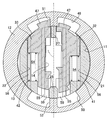
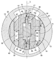
- FIG. 2 is a cross-sectional view of the cylinder lock at the third engagement position when the mechanical key is not inserted.
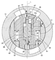
- FIG. 3 is a cross-sectional view at the third engagement position of the cylinder lock with the mechanical key inserted.
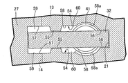
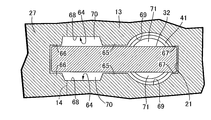
- (First embodiment) 4 is a cross-sectional view taken along line 4-4 of FIG.
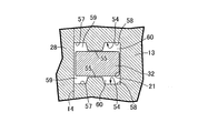
- (First embodiment) 5 is a cross-sectional view taken along line 5-5 of FIG.
- FIG. 6 shows a second embodiment and is a cross-sectional view of a cylinder lock corresponding to FIG. 2 in a state where a mechanical key is inserted.
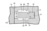
- (Second Embodiment) 7 is a cross-sectional view taken along line 7-7 of FIG.
- (Second Embodiment) 8 is a cross-sectional view taken along line 8-8 of FIG. (Second Embodiment)
- the cylinder lock includes a fixed cylinder body 12 having a cylinder hole 11 and a circular cross section. And a rotor 13 that is rotatably fitted in the cylinder hole 11, and a bottomed key insertion hole 14 having one end opened on one end surface of the rotor 13 at the center of the rotor 13. It is provided so as to extend along the axial direction of the rotor 13.
- the rotor 13 is engaged with the cylinder body 12 at a plurality of positions spaced apart in the axial direction of the rotor 13, that is, in this embodiment, five positions of first to fifth engagement positions P1, P2, P3, P4, and P5. In such an engaged state, the rotation of the rotor 13 relative to the cylinder body 12 is prevented.
- the regular mechanical key 15 is inserted into the key insertion hole 14, the engagement of the rotor 13 with the cylinder body 12 is released, and the rotor 13 can be rotationally driven in the cylinder body 12 by operating the mechanical key 15. it can.
- the mechanical key 15 is formed by integrally connecting an operation portion 15b to a rear end of a key main portion 15a having a rectangular cross-sectional shape and extending in a straight line.
- Protrusions 16 and 17 are formed at the front end side central portions of both surfaces of the main portion 15a by cutting both sides of both front end sides.
- the protrusions 16 and 17 have shapes that change sequentially as they move along the longitudinal direction of the key main portion 15a, and the protrusions 16 and 17 have the same shape. Alternatively, they may have different shapes.
- the rotor 13 has tumbler insertion holes arranged on both sides or one side of the diameter line L of the rotor 13 and opening both ends to the outer surface of the rotor 13 in a plane perpendicular to the axis of the rotor 13. Are provided at a plurality of positions spaced in the axial direction of the rotor 13 while crossing a part of the rotor 13, that is, at five positions of the first to fifth engagement positions P1 to P5.
- the rotor 13 has a pair of tumbler insertion holes 21 and 22 that are arranged on both sides of the diameter line L of the rotor 13 and open at both ends to the outer surface of the rotor 13 in a plane orthogonal to the axis of the rotor 13. 14, a pair of partition walls 27 disposed between the tumbler insertion holes 21 and 22 at a position sandwiching the key insertion hole 14 on one diameter line L of the rotor 13. 2 There is formed.
- the tumbler insertion holes 21 and 22 have half tumblers 32 and 33 having engaging portions 47 and 47 at one of both end portions along the one diameter line L, as shown in FIG. As shown in FIG. 3, the engaging portions 47 and 47 are inserted into the tumbler insertion holes according to the engagement position where the 47 protrudes from the outer surface of the rotor 13 and the insertion of the regular mechanical key 15 into the key insertion hole 14 as shown in FIG. 21 and 22 are inserted between the half tumblers 32 and 33 and the rotor 13 so as to be able to move to and from the disengagement positions to be retracted, and the half tumblers 32 and 33 are engaged with each other.
- the springs 41 and 42 biased to the position side are accommodated in the tumbler insertion holes 21 and 22, respectively.
- the second, fourth, and fifth engagement positions P2, P4, and P5 of the rotor 13 are arranged on both sides of the one diameter line L of the rotor 13 and Tumbler insertion holes 19, 20; 23, 24; 25, 26 that open at both ends to the outer surface of the rotor 13 in a plane orthogonal to the axis are provided so as to intersect with a part of the key insertion hole 14.
- Half tumblers 30, 31; 34, 35; 36, 37 are inserted into the tumbler insertion holes 19, 20; 23, 24; 25, 26, respectively, and the tumbler insertion holes 19, 20; 23, 24; Housed springs 39, 40; 43, 44; 45, 46 are provided between the half tumblers 30, 31; 34, 35; 36, 37 and the rotor 13, respectively.
- the rotor 13 is arranged on one side of the one diameter line L of the rotor 13 so that both ends are open to the outer surface of the rotor 13 in a plane perpendicular to the axis of the rotor 13.
- a tumbler insertion hole 18 is provided so as to intersect with a part of the key insertion hole 14, and is accommodated in the tumbler insertion hole 18 between the half tumbler 29 inserted into the tumbler insertion hole 18 and the rotor 13.
- a spring 38 is provided.
- the tumbler insertion holes 18; 19, 20; 21, 22; 23, 24; 25 in a state where the rotational position of the rotor 13 is in a neutral position.
- two pairs of locking recesses 49, 50; 51, 52 corresponding to both ends of the half tumblers 29; 30, 31; 32, 33; 34, 35; 36, 37 are provided so that the engaging portions 47 can be inserted and engaged.
- the inner side surfaces 54, 54 facing the half tumbler 32 of one 21 of the pair of tumbler insertion holes 21, 22 at the third engagement position P 3 from both sides are the half tumbler 32.
- the first guide portions 55, 55 extending in the moving direction of the half tumbler 32 in the vicinity and opposite to each other, and extending in the moving direction of the half tumbler 32 across the side edge of the key insertion hole 14 and the rotor 13
- the clearance between the half tumbler 32 and the first guide portion 55 is made larger by forming first escape passages 59, 59 opening both ends on the outer surface of the half tumbler 32.
- the first passage forming portions 57 and 57 are formed so as to have at least, and in this embodiment, the tumbler insertion hole 21 has the Movement of the half tumbler 32 includes side surfaces 54... Which move the first guide portion 55... And the second guide portions 56 and 56 extending in the moving direction of the half tumbler 32 in proximity to and opposite to the half tumbler 32.
- the inner side surface 54 is formed between the first and second guide portions 55..., 56... In the same manner as the first escape passage 59.
- a clearance between the half tumbler 32 is formed so as to form second escape passages 60, 60 extending in the moving direction of the half tumbler 32 and opening at both ends on the outer surface of the rotor 13. Are made larger than the first and second guide portions 55... 56.
- the second passage forming portions 58 are formed so as to have a circular arc-shaped curved portion 58a for accommodating the spring 41 having a coil shape.
- the inner surface of 26 is also formed in the same manner as the inner surface of the tumbler insertion hole 21 at the third engagement position P3.
- the inner side surfaces 54 facing the half tumblers 29 to 37 of the tumbler insertion holes 18 to 26 from both sides are adjacent to and opposed to the half tumblers 29 to 37.
- a first guide portion 55 extending in the moving direction of the half tumblers 29 to 37 and a side edge of the key insertion hole 14 extend in the moving direction of the half tumblers 29 to 37 and open both ends on the outer surface of the rotor 13.
- First clearance passages 59 are formed between the half tumblers 29 to 37 so that the clearance between the half tumblers 29 to 37 is larger than that of the first guide portion 55.
- the inner side surfaces 54 of the tumbler insertion holes 18 to 26 are in close proximity to and opposed to the first guide portions 55 and the half tumblers 29 to 37, and the second tumblers 29 to 37 extend in the moving direction. Since the guide portions 56 are formed so as to be spaced apart in the direction orthogonal to the moving direction of the half tumblers 29 to 37, foreign substances are formed in the first and second guide portions 55, 56, and half. It is possible to guide the movement of the half tumblers 29 to 37 while avoiding pinching between the side surfaces of the tumblers 29 to 37 as much as possible.
- FIGS. 6 to 8 A second embodiment of the present invention will be described with reference to FIGS. 6 to 8, but the parts corresponding to the first embodiment are indicated by the same reference numerals and shown in detail. The detailed explanation is omitted.
- Inner side surfaces 64, 64 facing the half tumbler 32 of one of the pair of tumbler insertion holes 21, 22 at the third engagement position P 3 from both sides are close to and opposed to the half tumbler 32, and the half tumbler 32 moves.
- the inner side surfaces 64 ... of the tumbler insertion holes 21 are formed with first guide portions 65 ...
- the second and third guide portions 66, 66; 67, 67 extending in the moving direction of the half tumbler 32 in the vicinity of and facing the half tumbler 32 are spaced in a direction perpendicular to the moving direction of the half tumbler 32. It is formed to have a gap.
- the second guide portions 66 are arranged at a position where the second guide portions 66 are divided into two at the key insertion hole 14 while continuing to a pair of partition walls 27 and 28 arranged on one diameter line L of the rotor 13.
- the inner side surfaces 64 of the tumbler insertion hole 21 are formed to have first passage forming portions 68 between the first and second guide portions 65, 66, and the first escape passages 70 are formed. Is formed between the inner side surface 64 of the tumbler insertion hole 21 and the half tumbler 32 between the first and second guide portions 65.
- the third guide portions 67 are arranged at positions that are continuous with the outer surface of the tumbler insertion hole 21, and the inner side surfaces 64 of the tumbler insertion hole 21 provide a clearance with the half tumbler 32.
- the second passage forming portions 69, 69 that are larger than the first to third guide portions 65, 66, 67, and so on are formed between the first and third guide portions 65, 67, and so on.
- the second passage forming portions 69 are formed in a circular arc shape in order to accommodate the coil-shaped spring 41.
- the inner surface of 26 is also formed in the same manner as the inner surface of the tumbler insertion hole 21 at the third engagement position P3.
Landscapes
- Physics & Mathematics (AREA)
- Electromagnetism (AREA)
- Lock And Its Accessories (AREA)
- Braking Arrangements (AREA)
Priority Applications (3)
| Application Number | Priority Date | Filing Date | Title |
|---|---|---|---|
| US14/396,169 US20150075237A1 (en) | 2012-04-25 | 2013-04-10 | Cylinder lock |
| CN201380021911.6A CN104246096B (zh) | 2012-04-25 | 2013-04-10 | 圆柱锁 |
| BR112014026174A BR112014026174A2 (pt) | 2012-04-25 | 2013-04-10 | fechadura cilíndrica |
Applications Claiming Priority (2)
| Application Number | Priority Date | Filing Date | Title |
|---|---|---|---|
| JP2012-099710 | 2012-04-25 | ||
| JP2012099710A JP5875071B2 (ja) | 2012-04-25 | 2012-04-25 | シリンダ錠 |
Publications (1)
| Publication Number | Publication Date |
|---|---|
| WO2013161564A1 true WO2013161564A1 (ja) | 2013-10-31 |
Family
ID=49482893
Family Applications (1)
| Application Number | Title | Priority Date | Filing Date |
|---|---|---|---|
| PCT/JP2013/060806 Ceased WO2013161564A1 (ja) | 2012-04-25 | 2013-04-10 | シリンダ錠 |
Country Status (5)
| Country | Link |
|---|---|
| US (1) | US20150075237A1 (enExample) |
| JP (1) | JP5875071B2 (enExample) |
| CN (1) | CN104246096B (enExample) |
| BR (1) | BR112014026174A2 (enExample) |
| WO (1) | WO2013161564A1 (enExample) |
Cited By (1)
| Publication number | Priority date | Publication date | Assignee | Title |
|---|---|---|---|---|
| CN108138515A (zh) * | 2015-09-08 | 2018-06-08 | 本田制锁有限公司 | 圆筒锁 |
Families Citing this family (3)
| Publication number | Priority date | Publication date | Assignee | Title |
|---|---|---|---|---|
| JP6000169B2 (ja) * | 2013-03-14 | 2016-09-28 | 株式会社ホンダロック | シリンダ錠 |
| JP6074812B2 (ja) * | 2013-12-13 | 2017-02-08 | 株式会社ホンダロック | シリンダ錠装置 |
| JP6638165B2 (ja) * | 2015-04-02 | 2020-01-29 | 本田技研工業株式会社 | シリンダ錠 |
Citations (2)
| Publication number | Priority date | Publication date | Assignee | Title |
|---|---|---|---|---|
| JPH02147562U (enExample) * | 1989-05-17 | 1990-12-14 | ||
| JP2008101432A (ja) * | 2006-10-20 | 2008-05-01 | Alpha Corp | シリンダ錠 |
Family Cites Families (23)
| Publication number | Priority date | Publication date | Assignee | Title |
|---|---|---|---|---|
| US1407868A (en) * | 1920-12-04 | 1922-02-28 | Oskar K Klein | Lock |
| US2395762A (en) * | 1942-01-02 | 1946-02-26 | Rober Anton | Padlock |
| US3705508A (en) * | 1969-03-14 | 1972-12-12 | Braun Pebra Gmbh | Locks |
| US3665740A (en) * | 1969-06-30 | 1972-05-30 | Goal Kk | Magnetic pin tumbler lock |
| DE1957642A1 (de) * | 1969-11-17 | 1971-09-02 | Ymos Metallwerke Wolf & Becker | Zylinderschloss |
| US4512166A (en) * | 1981-07-29 | 1985-04-23 | Ogden Industries Pty. Ltd. | Cylinder lock and key |
| US4450697A (en) * | 1981-09-10 | 1984-05-29 | Ellis Alan E H | Security devices for rotatable members and fluid flow control valves incorporating such devices |
| CH662610A5 (de) * | 1983-07-26 | 1987-10-15 | Uniswitch Ag | Sicherheitsschloss. |
| US4838051A (en) * | 1986-02-10 | 1989-06-13 | Yang Yaw Mein | Padlock and key assembly with transversely movable tumbler units and vertically movable tumbler units |
| JPS62194374A (ja) * | 1986-02-19 | 1987-08-26 | 株式会社クローバー | 錠装置 |
| US4802354A (en) * | 1987-01-16 | 1989-02-07 | Fort Lock Corporation | High security pin tumbler lock |
| US4890467A (en) * | 1988-05-31 | 1990-01-02 | Barry Krause | Switch lock |
| JPH0721776Y2 (ja) * | 1989-11-10 | 1995-05-17 | 株式会社東海理化電機製作所 | シリンダ錠 |
| US5600981A (en) * | 1995-02-03 | 1997-02-11 | Strattec Security Corporation | Snap-in tumbler |
| US5699687A (en) * | 1996-06-06 | 1997-12-23 | Pittman; John M. | Firearm security device |
| US5970762A (en) * | 1996-10-10 | 1999-10-26 | Fort Lock Corporation | Lock plug assembly and a tumbler with a bent-over end therefor |
| JP3676606B2 (ja) * | 1999-02-12 | 2005-07-27 | 株式会社ホンダロック | シリンダ錠 |
| JP3943846B2 (ja) * | 2001-02-19 | 2007-07-11 | 株式会社ユーシン | シリンダ錠 |
| SK287651B6 (sk) * | 2001-05-22 | 2011-05-06 | Fab, A. S. | Valcová zámka, predovšetkým do motorových vozidiel |
| US7634930B2 (en) * | 2002-01-03 | 2009-12-22 | Strattec Security Corporation | Lock apparatus and method |
| JP4391718B2 (ja) * | 2002-01-22 | 2009-12-24 | 株式会社東海理化電機製作所 | シリンダ錠 |
| US7114357B2 (en) * | 2002-09-26 | 2006-10-03 | Newfrey, Llc | Keying system and method |
| DE10313125A1 (de) * | 2003-03-24 | 2004-10-14 | Huf Hülsbeck & Fürst Gmbh & Co. Kg | Schließzylinder |
-
2012
- 2012-04-25 JP JP2012099710A patent/JP5875071B2/ja active Active
-
2013
- 2013-04-10 CN CN201380021911.6A patent/CN104246096B/zh not_active Expired - Fee Related
- 2013-04-10 US US14/396,169 patent/US20150075237A1/en not_active Abandoned
- 2013-04-10 BR BR112014026174A patent/BR112014026174A2/pt not_active Application Discontinuation
- 2013-04-10 WO PCT/JP2013/060806 patent/WO2013161564A1/ja not_active Ceased
Patent Citations (2)
| Publication number | Priority date | Publication date | Assignee | Title |
|---|---|---|---|---|
| JPH02147562U (enExample) * | 1989-05-17 | 1990-12-14 | ||
| JP2008101432A (ja) * | 2006-10-20 | 2008-05-01 | Alpha Corp | シリンダ錠 |
Cited By (2)
| Publication number | Priority date | Publication date | Assignee | Title |
|---|---|---|---|---|
| CN108138515A (zh) * | 2015-09-08 | 2018-06-08 | 本田制锁有限公司 | 圆筒锁 |
| CN108138515B (zh) * | 2015-09-08 | 2019-11-15 | 本田制锁有限公司 | 圆筒锁 |
Also Published As
| Publication number | Publication date |
|---|---|
| US20150075237A1 (en) | 2015-03-19 |
| JP5875071B2 (ja) | 2016-03-02 |
| BR112014026174A2 (pt) | 2017-06-27 |
| CN104246096A (zh) | 2014-12-24 |
| JP2013227761A (ja) | 2013-11-07 |
| CN104246096B (zh) | 2018-01-23 |
Similar Documents
| Publication | Publication Date | Title |
|---|---|---|
| US8261588B2 (en) | Cylinder lock and key combination | |
| CA2652582C (en) | Key and disc tumbler cylinder lock | |
| WO2013161564A1 (ja) | シリンダ錠 | |
| CZ338599A3 (cs) | Kombinace válcového zámku a klíče | |
| KR101955781B1 (ko) | 모듈식 잠금장치 플러그 | |
| AU2009281417A1 (en) | Cylinder lock with cylinder housing and flat key for a cylinder lock | |
| JP2013227761A5 (enExample) | ||
| ITRM20110299A1 (it) | Sistema di agganciamento o sganciamento di elementi sovrapponibili. | |
| JP6389157B2 (ja) | シリンダ錠 | |
| JP2016138423A (ja) | シリンダー錠用の鍵 | |
| JP6462304B2 (ja) | レジスタ | |
| TWI635014B (zh) | 主開關鎖帶動機構 | |
| KR102022815B1 (ko) | 잠금 요소를 갖는 플러그 커넥터 | |
| JP6343422B2 (ja) | ロータリーディスクタンブラー錠 | |
| JP3676606B2 (ja) | シリンダ錠 | |
| US8894432B1 (en) | Connector assembly | |
| GB2541322A (en) | A cylinder lock having a clutch mechanism with an axially movable tab | |
| JP2022520027A (ja) | ブランクキーおよびキーにおけるキー組合せ要素 | |
| CN201221261Y (zh) | 具弹性闭锁组件的枢轴结构 | |
| CN106049998A (zh) | 圆柱锁 | |
| CN114502858A (zh) | 啮合链条及可动体移动装置 | |
| JP2010212047A (ja) | レバー式コネクタ | |
| JP2008223386A (ja) | シリンダ錠 | |
| HK1132775B (en) | Key and disc tumbler cylinder lock |
Legal Events
| Date | Code | Title | Description |
|---|---|---|---|
| 121 | Ep: the epo has been informed by wipo that ep was designated in this application |
Ref document number: 13781252 Country of ref document: EP Kind code of ref document: A1 |
|
| WWE | Wipo information: entry into national phase |
Ref document number: 14396169 Country of ref document: US |
|
| WWE | Wipo information: entry into national phase |
Ref document number: IDP00201406533 Country of ref document: ID |
|
| NENP | Non-entry into the national phase |
Ref country code: DE |
|
| REG | Reference to national code |
Ref country code: BR Ref legal event code: B01A Ref document number: 112014026174 Country of ref document: BR |
|
| 122 | Ep: pct application non-entry in european phase |
Ref document number: 13781252 Country of ref document: EP Kind code of ref document: A1 |
|
| ENP | Entry into the national phase |
Ref document number: 112014026174 Country of ref document: BR Kind code of ref document: A2 Effective date: 20141020 |