WO2013157458A1 - Électrode, son procédé de fabrication et élément secondaire - Google Patents
Électrode, son procédé de fabrication et élément secondaire Download PDFInfo
- Publication number
- WO2013157458A1 WO2013157458A1 PCT/JP2013/060814 JP2013060814W WO2013157458A1 WO 2013157458 A1 WO2013157458 A1 WO 2013157458A1 JP 2013060814 W JP2013060814 W JP 2013060814W WO 2013157458 A1 WO2013157458 A1 WO 2013157458A1
- Authority
- WO
- WIPO (PCT)
- Prior art keywords
- substituted
- unsubstituted
- group
- active material
- positive electrode
- Prior art date
Links
Images

Classifications
-
- H—ELECTRICITY
- H01—ELECTRIC ELEMENTS
- H01M—PROCESSES OR MEANS, e.g. BATTERIES, FOR THE DIRECT CONVERSION OF CHEMICAL ENERGY INTO ELECTRICAL ENERGY
- H01M4/00—Electrodes
- H01M4/02—Electrodes composed of, or comprising, active material
- H01M4/13—Electrodes for accumulators with non-aqueous electrolyte, e.g. for lithium-accumulators; Processes of manufacture thereof
- H01M4/139—Processes of manufacture
- H01M4/1399—Processes of manufacture of electrodes based on electro-active polymers
-
- H—ELECTRICITY
- H01—ELECTRIC ELEMENTS
- H01M—PROCESSES OR MEANS, e.g. BATTERIES, FOR THE DIRECT CONVERSION OF CHEMICAL ENERGY INTO ELECTRICAL ENERGY
- H01M4/00—Electrodes
- H01M4/02—Electrodes composed of, or comprising, active material
- H01M4/13—Electrodes for accumulators with non-aqueous electrolyte, e.g. for lithium-accumulators; Processes of manufacture thereof
- H01M4/137—Electrodes based on electro-active polymers
-
- H—ELECTRICITY
- H01—ELECTRIC ELEMENTS
- H01M—PROCESSES OR MEANS, e.g. BATTERIES, FOR THE DIRECT CONVERSION OF CHEMICAL ENERGY INTO ELECTRICAL ENERGY
- H01M4/00—Electrodes
- H01M4/02—Electrodes composed of, or comprising, active material
- H01M4/36—Selection of substances as active materials, active masses, active liquids
- H01M4/60—Selection of substances as active materials, active masses, active liquids of organic compounds
- H01M4/602—Polymers
- H01M4/606—Polymers containing aromatic main chain polymers
-
- H—ELECTRICITY
- H01—ELECTRIC ELEMENTS
- H01M—PROCESSES OR MEANS, e.g. BATTERIES, FOR THE DIRECT CONVERSION OF CHEMICAL ENERGY INTO ELECTRICAL ENERGY
- H01M4/00—Electrodes
- H01M4/02—Electrodes composed of, or comprising, active material
- H01M4/64—Carriers or collectors
- H01M4/66—Selection of materials
- H01M4/665—Composites
- H01M4/667—Composites in the form of layers, e.g. coatings
-
- H—ELECTRICITY
- H01—ELECTRIC ELEMENTS
- H01M—PROCESSES OR MEANS, e.g. BATTERIES, FOR THE DIRECT CONVERSION OF CHEMICAL ENERGY INTO ELECTRICAL ENERGY
- H01M4/00—Electrodes
- H01M4/02—Electrodes composed of, or comprising, active material
- H01M4/36—Selection of substances as active materials, active masses, active liquids
- H01M4/60—Selection of substances as active materials, active masses, active liquids of organic compounds
- H01M4/602—Polymers
- H01M4/606—Polymers containing aromatic main chain polymers
- H01M4/608—Polymers containing aromatic main chain polymers containing heterocyclic rings
-
- Y—GENERAL TAGGING OF NEW TECHNOLOGICAL DEVELOPMENTS; GENERAL TAGGING OF CROSS-SECTIONAL TECHNOLOGIES SPANNING OVER SEVERAL SECTIONS OF THE IPC; TECHNICAL SUBJECTS COVERED BY FORMER USPC CROSS-REFERENCE ART COLLECTIONS [XRACs] AND DIGESTS
- Y02—TECHNOLOGIES OR APPLICATIONS FOR MITIGATION OR ADAPTATION AGAINST CLIMATE CHANGE
- Y02E—REDUCTION OF GREENHOUSE GAS [GHG] EMISSIONS, RELATED TO ENERGY GENERATION, TRANSMISSION OR DISTRIBUTION
- Y02E60/00—Enabling technologies; Technologies with a potential or indirect contribution to GHG emissions mitigation
- Y02E60/10—Energy storage using batteries
Definitions
- the present invention relates to an electrode, a method for manufacturing the electrode, and a secondary battery, and more particularly to an electrode in which an electrode active material is mainly formed of an organic compound, a method for manufacturing the electrode, and a secondary battery using the electrode.
- lithium ion secondary batteries using an alkali metal ion such as lithium ion as a charge carrier and utilizing an electrochemical reaction accompanying the charge transfer have been developed.
- lithium ion secondary batteries have a high energy density and are becoming widespread as in-vehicle batteries.
- the electrode active material is a substance that directly contributes to the battery electrode reaction such as the charge reaction and the discharge reaction, and has the central role of the secondary battery. That is, the battery electrode reaction is a reaction that occurs with the transfer of electrons by applying a voltage to an electrode active material that is electrically connected to an electrode disposed in the electrolyte, and proceeds during charging and discharging of the battery. To do. Therefore, as described above, the electrode active material has a central role of the secondary battery in terms of system.
- a lithium-containing transition metal oxide is used as a positive electrode active material
- a carbon material is used as a negative electrode active material
- an insertion reaction and a desorption reaction of lithium ions with respect to these electrode active materials are used. Charging / discharging.
- the lithium ion secondary battery has a problem in that the speed of charging and discharging is limited because the movement of lithium ions in the positive electrode is rate limiting. That is, in the above-described lithium ion secondary battery, the migration rate of lithium ions in the transition metal oxide of the positive electrode is slower than that of the electrolyte and the negative electrode, and therefore the battery reaction rate at the positive electrode becomes the rate-determining rate. As a result, there is a limit to increasing the output and shortening the charging time.
- Patent Document 1 is known as a prior art document using an organic radical compound as an electrode active material.
- Patent Document 1 discloses a secondary battery active material using a nitroxyl radical compound, an oxy radical compound, and a nitrogen radical compound having a radical on a nitrogen atom.
- the unpaired electrons that react are localized in the radical atoms, so that the concentration of the reaction site can be increased, and thus a high-capacity secondary battery can be realized. Further, since the reaction rate of radicals is high, it is considered that the charging time can be completed in a short time by performing charging / discharging utilizing a redox reaction of a stable radical.
- Example using the highly stable nitroxyl radical as a radical is described, for example, the electrode layer containing a nitronyl nitroxide compound is used as a positive electrode, and lithium bonding copper foil is used as a negative electrode. It was confirmed that charging / discharging was possible over 10 cycles or more when a secondary battery was manufactured and repeatedly charged / discharged.
- Patent Documents 2 and 3 are known as prior art documents using an organic sulfur compound as an electrode active material.
- Patent Document 2 discloses a novel organic sulfur compound, which is a positive electrode material, has an SS bond in a charged state, and the SS bond is cleaved during discharge of the positive electrode to form an organic sulfur metal salt having a metal ion.
- Metal-sulfur battery cells have been proposed.
- disulfide compound a disulfide organic compound represented by the general formula (1 ′) (hereinafter referred to as “disulfide compound”) is used as the organic sulfur compound.
- R represents an aliphatic organic group or an aromatic organic group, and each includes the same or different cases.
- the disulfide compound can undergo a two-electron reaction, and the S—S bond is cleaved in a reduced state (discharge state), thereby forming an organic thiolate (R—SH).
- This organic thiolate forms an S—S bond in the oxidized state (charged state) and is restored to the disulfide compound represented by the general formula (1 ′).
- the disulfide compound forms an SS bond having a small binding energy, a reversible redox reaction occurs using the bond and cleavage by the reaction, and thus charge and discharge can be performed.
- Patent Document 3 discloses the following formula (2 ′): -(NH-CS-CS-NH) (2 ')
- a battery electrode containing rubeanic acid or rubeanic acid polymer which has a structural unit represented by
- the rubeanic acid or rubeanic acid polymer containing a dithione structure represented by the general formula (2 ′) binds to lithium ions during reduction, and releases the bound lithium ions during oxidation. Charging / discharging can be performed by utilizing such a reversible oxidation-reduction reaction of rubeanic acid or rubeanic acid polymer.
- Patent Document 3 when rubeanic acid is used as the positive electrode active material, a two-electron reaction is possible, and a secondary battery having a capacity density of 400 Ah / kg at room temperature is obtained.
- an active material paste containing an electrode active material is prepared, and the active material paste is applied to an electrode current collector made of a metal foil having an acid-resistant film such as Al.
- an electrode current collector made of a metal foil having an acid-resistant film such as Al.
- a material in which an electrode active material layer is formed on the surface of an electrode current collector is known.
- Patent Document 4 discloses a general formula Li [Li x (Ni y M 1-y ) 1-x ] O 2 (where x is 0.01 to 0.10 and y is 0.5 to 0.8).
- M is at least one element selected from Co, Mn, Al, Mg, Ti, Fe, Cr, Si, Zr), and a method for producing a positive electrode active material for a non-aqueous electrolyte secondary battery, Production of a positive electrode active material for a non-aqueous electrolyte secondary battery, wherein the positive electrode active material is neutralized using an acidic solution having a pH of 3.0 to 6.0, and then the neutralized product is removed by washing with water.
- a method has been proposed.
- This Patent Document 4 attempts to suppress the corrosion of the Al foil, which is a positive electrode current collector, by removing the alkaline component present on the surface of the positive electrode active material.
- Patent Document 5 discloses a method for manufacturing a secondary battery comprising an electrode in which an active material layer is formed using an alkaline active material paste on a metal foil current collector that can be corroded by an alkali.
- the electrode forming step includes: an application step of applying the active material paste to the metal foil current collector; and the active material paste applied to the metal foil current collector.
- Proposing a method for producing a secondary battery comprising: a drying step for drying the metal foil; and a low-temperature holding step for keeping the metal foil current collector at a low temperature of 12 ° C. or lower between the coating step and immediately before the drying step. Has been.
- the metal foil current collector after applying an active material paste to a metal foil current collector, the metal foil current collector is kept at a low temperature of 12 ° C. or lower until the active material paste is dried. During the period from the process to just before the drying process, it is difficult for the alkali of the active material paste to react with the metal foil current collector, thereby preventing the metal foil current collector from corroding by the alkali, and the metal foil An attempt is made to suppress the formation of an electrically insulating film on the current collector.
- JP 2004-207249 A paragraph numbers [0278] to [0282]
- US Pat. No. 4,833,048 (Claim 1, column 5, line 20 to column 28)
- JP 2008-147015 A (Claim 1, paragraph number [0011], FIG. 3, FIG. 5)
- JP 2009-230863 A (Claim 1, paragraph numbers [0014] to [0018], FIGS. 1 and 3)
- JP 2007-042370 A (Claim 1, paragraph number [0010])
- Patent Documents 1 to 3 by using a specific organic compound as an electrode active material, a secondary battery having a high capacity and a high output can be realized, and usefulness when these organic compounds are used as an electrode active material. Is described.
- Patent Document 4 and Patent Document 5 the positive electrode active material is subjected to an acid treatment, or the metal foil current collector is maintained at a low temperature after the application of the active material paste, whereby the metal foil current collector generated at the time of electrode formation. It is intended to suppress corrosion and is not intended to reduce the internal resistance of the electrode, nor is an organic compound used as the electrode active material.
- the present invention has been made in view of such circumstances, and an electrode capable of maintaining a high output even after repeated charge and discharge and capable of obtaining a secondary battery with good cycle characteristics and a long cycle life, and its manufacture It is an object to provide a method, a secondary battery using the method, and a manufacturing method thereof.
- the inventors of the present invention have made extensive studies to achieve the above-mentioned object.
- the current collector made of a metal foil containing a valve metal is subjected to an alkali treatment, and an oxide film is formed on the surface of the current collector.
- the adhesion between the active material layer and the current collector is improved, thereby reducing the internal resistance.
- an electrode for a secondary battery having good cycle characteristics capable of maintaining a high output even after repeated charge and discharge can be obtained.
- the electrode according to the present invention includes a current collector and an active material layer formed on the surface of the current collector, and the active material layer Is mainly composed of an organic compound, and the current collector is formed of a metal foil containing a valve action metal, and the surface of the metal foil is formed of an oxide film forming site on which an oxide film is formed and the oxide film. It is characterized by having an oxide film non-formation part which is not formed.
- the metal foil is preferably subjected to alkali treatment.
- the organic compound preferably contains at least one of an organic radical compound containing a stable radical group, a rubeanic acid compound having a rubeanic acid structure, and a dione compound having a dione structure.
- the organic radical compound is preferably a nitroxyl radical compound.
- the nitroxyl radical compound preferably contains 2,2,6,6-tetramethylpiperidine-N-oxyl radical in the molecular structure.
- the rubeanic acid compound has the general formula
- n is an integer of 1 or more
- R 1 and R 2 are a hydrogen atom, a substituted or unsubstituted imino group, a substituted or unsubstituted alkylene group, a substituted or unsubstituted arylene group. And at least one of R 1 and R 2 includes the same case.
- the dione compound has the general formula
- At least two of X 1 to X 4 are oxygen atoms
- R 3 to R 6 and X 1 to X 4 other than the oxygen atoms are hydrogen atoms, hydroxyl groups, substituted or Unsubstituted alkyl group, substituted or unsubstituted aryl group, substituted or unsubstituted aralkyl group, substituted or unsubstituted cycloalkyl group, substituted or unsubstituted alkoxyl group, substituted or unsubstituted alkenyl group, substituted or unsubstituted Substituted aryloxy group, substituted or unsubstituted arylamino group, substituted or unsubstituted alkylamino group, substituted or unsubstituted thioaryl group, substituted or unsubstituted thioalkyl group, substituted or unsubstituted heterocyclic group, substituted Or an unsubstituted
- the dione compound has the general formula
- X 5 to X 8 are oxygen atoms
- Y, Z, R 7 to R 10 , and X 5 to X 8 other than the oxygen atoms are hydrogen atoms, Hydroxyl group, substituted or unsubstituted alkyl group, substituted or unsubstituted aryl group, substituted or unsubstituted aralkyl group, substituted or unsubstituted cycloalkyl group, substituted or unsubstituted alkoxyl group, substituted or unsubstituted alkenyl group
- the electrode manufacturing method according to the present invention includes adding a solvent and a pH adjuster to an active material raw material mainly composed of an organic compound to produce an active material paste having a pH adjusted to 8 to 11, thereby producing a valve action metal.
- the active material paste is coated on the surface of the metal foil containing the metal foil, the oxide film is formed by applying an alkali treatment to the metal foil, and the oxide film non-forming part where the oxide film is not formed Are formed on the surface of the metal foil, and an active material layer is formed on the surface of the metal foil as a current collector.
- the active material paste preferably contains a conductive agent and a binder.
- the secondary battery according to the present invention has a positive electrode, a negative electrode, and an electrolyte
- the organic compound according to any of the above is a reaction starting material, a product, and an intermediate product in at least a discharge reaction of the battery electrode reaction. It is characterized by being included in either of them.
- the electrode of the present invention has a current collector and an active material layer formed on the surface of the current collector.
- the active material layer is mainly composed of an organic compound, and the current collector is
- the surface of the metal foil has an oxide film forming part where an oxide film is formed and an oxide film non-forming part where the oxide film is not formed. Therefore, the current collector and the active material layer are intertwined and firmly bonded, and a so-called anchor effect is exhibited. As a result, the adhesion between the current collector and the active material layer is improved, and thereby the internal resistance can be reduced. Since the active material layer is mainly composed of an organic compound, an electrode capable of charge / discharge reaction with a large current can be obtained.
- a solvent and a pH adjuster are added to an active material raw material mainly composed of an organic compound, an active material paste having a pH adjusted to 8 to 11 is produced, and a valve action metal is added.
- the active material paste is applied to the surface of the contained metal foil, the oxide film is formed by applying an alkali treatment to the metal foil, and the oxide film non-forming part where the oxide film is not formed Is formed on the surface of the metal foil, and an active material layer is formed on the surface of the metal foil that is a current collector.
- the adhesion between the current collector and the active material layer is improved by a so-called anchor effect, and an electrode that has a small internal resistance and can be charged and discharged with a large current can be easily manufactured.
- the secondary battery of the present invention has a positive electrode, a negative electrode, and an electrolyte, and the organic compound according to any one of the above is a reaction starting material, a product, and an intermediate product in at least a discharge reaction of the battery electrode reaction. Therefore, it is possible to maintain a high output even after repeated charging and discharging, to obtain a secondary battery with good cycle characteristics, low environmental impact and low safety in consideration of safety. it can.
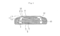
- FIG. 1 is a cross-sectional view showing a coin-type secondary battery as an embodiment of a secondary battery according to the present invention.
- the battery can 1 has a positive electrode case 2 and a negative electrode case 3, and both the positive electrode case 2 and the negative electrode case 3 are formed in a disk-like thin plate shape.
- a positive electrode current collector 4 is disposed at the center of the bottom of the positive electrode case 2, and a positive electrode active material (active material layer) 5 is formed on the surface of the positive electrode current collector 4.
- the positive electrode current collector 4 constitute a positive electrode (electrode) 6.
- a separator 7 formed of a porous film such as polypropylene is laminated on the positive electrode 6, and a negative electrode 10 having a negative electrode current collector 8 and a negative electrode active material 9 is further laminated on the separator 7.
- the negative electrode active material 9 for example, a material obtained by superimposing a lithium metal foil on Cu or a material obtained by applying a lithium storage material such as graphite or hard carbon to the metal foil can be used.
- the negative electrode current collector 8 is made of a metal material such as Cu.
- a metal spring 11 is seated on the negative electrode 10, and an electrolyte 12 is injected into the internal space, and the negative electrode case 3 is fixed to the positive electrode case 2 against the urging force of the metal spring 11, It is sealed via a gasket 13.
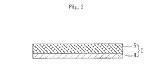
- FIG. 2 is an enlarged cross-sectional view of the positive electrode 6.
- the positive electrode active material layer 5 is formed on the surface of the positive electrode current collector 4 as described above.
- the positive electrode current collector 4 is formed of a metal foil containing a valve metal, and the surface of the positive electrode current collector 4 is subjected to an alkali treatment to form an oxide film formation site and an oxide film. And a non-oxidized film forming part.
- the valve metal is not particularly limited as long as it has a valve action, and an oxide film formation site and an oxide film non-formation site can be obtained by alkali treatment.
- Al, Ta, Ti, Nb, Zr and alloys containing these can be used, and among these, Al and Ta can be particularly preferably used.
- the distribution state of the oxide film formation site and the oxide film non-formation site and the ratio of both are not particularly limited. That is, it is considered that a mottled pattern is preferable in order to obtain a desired anchor effect, but the desired effect is sufficiently obtained if at least 0.1% or more of an oxide film forming site is present in the positive electrode current collector 4. Seems to be able to.
- the positive electrode active material layer 5 is mainly composed of an organic compound and contains an appropriate amount of a conductive agent, a binder, and the like.
- the positive electrode 6 includes the positive electrode current collector 4 and the positive electrode active material layer 5 formed on the surface of the positive electrode current collector 4, and the positive electrode active material layer 5 is mainly composed of an organic compound.
- the positive electrode current collector 4 is formed of a metal foil containing a valve action metal, and the surface of the metal foil has an oxide film formation site and an oxide film non-formation site.
- the electric body 4 and the positive electrode active material layer 5 are entangled and firmly bonded to each other, and a so-called anchor effect is exhibited.
- the adhesion between the positive electrode current collector 4 and the positive electrode active material layer 5 is improved, thereby making it possible to reduce the internal resistance, and the positive electrode active material layer 5 is mainly composed of an organic compound.
- an electrode capable of charge / discharge reaction with a large current can be obtained.
- the positive electrode active material layer 5 mainly composed of an organic compound can be charged and discharged with a large current, it can maintain a high output even after repeated charging and discharging, and has a long cycle life with a good cycle characteristic.
- a secondary battery can be obtained.
- the adhesion between the positive electrode current collector 4 and the positive electrode active material layer 5 is improved as described above, the interfacial separation between the positive electrode current collector 4 and the positive electrode active material layer 5 is minimized as long as charge and discharge are repeated. Therefore, a secondary battery with improved cycle life can be obtained.
- FIG. 3 is a charge / discharge curve showing an example of the battery characteristics of the secondary battery.
- the horizontal axis represents capacity density (mAh / g)
- the vertical axis represents voltage (V).
- a secondary battery normally, as shown in FIG. 3, when charging is started, the voltage rapidly rises to the vicinity of the specific voltage V, and the voltage becomes a substantially constant value in the vicinity of the specific voltage V. As part A is formed and the end of charging approaches, the voltage suddenly rises again. Further, when the discharge is started, the voltage rapidly decreases to the vicinity of the specific voltage V, the voltage becomes a substantially constant value near the specific voltage V to form the voltage flat portion A ′, and when the end of the discharge approaches. The voltage drops rapidly again.
- the main body of the positive electrode active material layer 5 is formed of an organic compound
- the gradient at the time of transition from the charge / discharge start to the voltage flat portions A and A ′ and The gradient at the time of transition from the voltage flat portions A and A ′ to the end of charging / discharging is small, and it is difficult to monitor the charging / discharging state of the voltage in the charging / discharging curve. Therefore, conventionally, the charge / discharge state of the secondary battery has to be confirmed by measuring the amount of electric charge.
- organic compound that is the main component of the positive electrode active material layer 5 it is preferable to use an organic radical compound containing a stable radical group, a rubeanic acid compound having a rubeanic acid structure, or a dione compound having a dione structure.
- organic radical compounds can rapidly advance the charge / discharge reaction.
- the organic radical compound has a radical which is an unpaired electron in the outermost shell of the electron orbit.
- These radicals are generally highly reactive chemical species, and many of them disappear with a certain lifetime due to interaction with surrounding substances, but they are stable depending on the state of resonance effect, steric hindrance, and solvation. It becomes a stable radical that exists stably for a long time.
- a nitroxyl radical group As a stable radical group contained in such an organic radical compound, a nitroxyl radical group, a nitrogen radical group, an oxygen radical group, a thioaminyl radical group, a sulfur radical group, a boron radical group, etc. can be used.
- a nitroxyl radical group represented by the general formula (1) is preferable.
- the following chemical reaction formula (I) shows an example of a charge / discharge reaction expected when a nitroxyl radical compound containing a nitroxyl radical group is used as an electrode active material and Li is used as a cation of an electrolyte salt. ing.
- a compound containing a 2,2,6,6-tetramethylpiperidine-N-oxyl radical structure represented by the general formula (2) in the molecular structure has a stable charge / discharge reaction. It is particularly preferable because it proceeds.
- Examples of the organic compound included in the category of the chemical formula (2) include those represented by the chemical formulas (2a) to (2f) and copolymers having these as a part of the repeating unit.
- n is an integer of 1 or more
- R 1 and R 2 are a hydrogen atom, a substituted or unsubstituted imino group, a substituted or unsubstituted alkylene group, a substituted or unsubstituted arylene group. And at least one of R 1 and R 2 includes the same case.
- the following chemical reaction formula (II) shows an example of a charge / discharge reaction expected when a rubeanic acid compound is used as an electrode active material and Li is used as a cation of an electrolyte salt.
- the rubeanic acid compound is excellent in stability during charge and discharge (oxidized state and reduced state), a multi-electron reaction of two or more electrons is possible by a redox reaction. Thereby, a secondary battery having a high capacity density can be obtained.
- Examples of the organic compound included in the category of the general formula (3) include those represented by the chemical formulas (3a) to (3c) and copolymers having these as a part of the repeating unit.
- the following chemical reaction formula (III) shows an example of a charge / discharge reaction expected when a dione compound is used as an electrode active material and Li is used as a cation for obtaining an electrolyte.
- the dione compound is also excellent in stability in the oxidation state and the reduction state, and therefore, a multi-electron reaction of two or more electrons is possible by the oxidation-reduction reaction.
- a secondary battery can be obtained.
- the compounds represented by the general formulas (4A) and (4B) are particularly preferable because they exhibit a more stable oxidation-reduction reaction, contribute to realization of a multi-electron reaction, and can be densified. .
- At least two or more of X 1 to X 4 and at least two of X 5 to X 8 are oxygen atoms, Y, Z, R 3 to R 10 , and the above X 1 to X 8 other than the oxygen atom are hydrogen atom, hydroxyl group, substituted or unsubstituted alkyl group, substituted or unsubstituted aryl group, substituted or unsubstituted aralkyl group, substituted or unsubstituted cycloalkyl group, substituted Or an unsubstituted alkoxyl group, a substituted or unsubstituted alkenyl group, a substituted or unsubstituted aryloxy group, a substituted or unsubstituted arylamino group, a substituted or unsubstituted alkylamino group, a substituted or unsubstituted thioaryl group, Substituted or unsubstituted thio
- X 1 to X 4 in the general formula (4A) and X 5 to X 8 in the general formula (4B) are each two or more of oxygen atoms as described above, and the others are optional substitutions described above.
- a group can be used, but the other part preferably has a low molecular weight because a desired battery characteristic is exhibited in the dione structure part, and a hydrogen atom is preferred from this viewpoint.
- Examples of the organic compound included in the category of the general formula (4A) include those represented by the chemical formulas (4A 1 ) and (4A 2 ) and copolymers having these as a part of the repeating unit.
- Examples of the organic compound included in the category of the general formula (4B) include those represented by the chemical formulas (4B 1 ) and (4B 2 ) and copolymers having these as a part of the repeating unit.
- the positive electrode active material is reversibly oxidized or reduced by charge / discharge, so that it is in a charged state, a discharged state, or a halfway state.
- the positive electrode active material includes at least a reaction starting material in the discharge reaction (a material that causes a chemical reaction in the battery electrode reaction), a product (a material that is generated as a result of the chemical reaction), And any of the intermediate products.
- the positive electrode active material is mainly composed of an organic compound, a secondary battery with low environmental impact and safety can be obtained.
- the above-described positive electrode active material 5 mainly composed of an organic compound is mixed with a conductive agent and a binder, and sodium hydroxide, phosphoric acid, boron, and an organic solvent and pure water are mixed so that the pH is 8-11.
- An active material paste is prepared by adding a pH adjusting agent such as acid or carbonic acid.
- pH of an active material paste is measured with a pH meter or pH test paper, and pH is controlled to the above-mentioned range.
- the conductive agent is not particularly limited, for example, carbonaceous fine particles such as graphite, carbon black, acetylene black, carbon fibers such as vapor grown carbon fiber, carbon nanotube, carbon nanohorn, polyaniline, polypyrrole, Conductive polymers such as polythiophene, polyacetylene, and polyacene can be used. Further, two or more kinds of conductive agents can be mixed and used.
- the content of the conductive agent in the positive electrode active material 5 is preferably 10 to 80% by mass.
- the binder is not particularly limited, such as polyethylene, polypropylene, polyvinylidene fluoride, polyhexafluoropropylene, polytetrafluoroethylene, polyethylene oxide, carboxymethyl cellulose, styrene butadiene copolymer, polymethyl acrylate, etc.
- Various resins can be used alone or in combination of two or more.
- the organic solvent contained in the active material paste is not particularly limited.
- bases such as dimethyl sulfoxide, dimethylformamide, N-methyl-2-pyrrolidone, propylene carbonate, diethyl carbonate, dimethyl carbonate, and ⁇ -butyrolactone are used.
- An organic solvent such as an organic solvent, a non-aqueous solvent such as acetonitrile, tetrahydrofuran, nitrobenzene, and acetone, and a protic solvent such as methanol and ethanol can be used.
- the content of the organic solvent in the active material paste is usually 99% by mass or less.
- the active material paste thus adjusted to a pH of 8 to 11 is coated on a metal foil made of a valve metal such as Al by an arbitrary coating method, whereby an alkali treatment is applied to the surface of the metal foil. Is applied to form an oxide film formation site and an oxide film non-formation site. Thereafter, the positive electrode 6 having the positive electrode active material 5 formed on the surface of the positive electrode current collector 4 is produced by drying for a predetermined time.
- the electrolyte 12 is prepared.
- the electrolyte 12 is interposed between the positive electrode 6 and the negative electrode 10 which is the opposite electrode of the positive electrode 6 to transport charge carriers between both electrodes.
- an electrolyte 12 for example, 10 ⁇ 5 at room temperature.
- a material having an ionic conductivity of ⁇ 10 ⁇ 1 S / cm is used, and an electrolyte salt dissolved in an organic solvent is used.
- electrolyte salt for example, LiPF 6 , LiClO 4 , LiBF 4 , LiCF 3 SO 3 , LiN (CF 3 SO 2 ) 2 , LiN (C 2 F 5 SO 2 ) 2 , LiC (CF 3 SO 2 ) 3 , LiC (C 2 F 5 SO 2 ) 3 and the like.
- Examples of the organic solvent contained in the electrolyte 12 include ethylene carbonate, propylene carbonate, dimethyl carbonate, diethyl carbonate, methyl ethyl carbonate, ⁇ -butyrolactone, tetrahydrofuran, dioxolane, sulfolane, dimethylformamide, dimethylacetamide, and N-methyl-2.
- -Pyrrolidone or the like can be used.
- the type of organic solvent, the compounding ratio of the organic compound and the organic solvent, the type of additive and the amount added, etc. should be set arbitrarily in consideration of the required characteristics and productivity of the secondary battery. Can do.
- the positive electrode 6 is impregnated in the electrolyte 12, and the negative electrode 10 is disposed so as to face the positive electrode 6 through the separator 7 impregnated with the electrolyte 12, and then the electrolyte 9 is injected into the internal space.
- a metal spring 11 is seated on the negative electrode 10 and a gasket 13 is arranged on the periphery, and the negative electrode case 3 is fixed to the positive electrode case 2 with a caulking machine or the like, and is externally sealed, thereby a coin-type secondary battery. Is produced.
- a solvent and a pH adjuster are added to an active material raw material mainly composed of an organic compound to produce an active material paste having a pH adjusted to 8 to 11, and a valve action metal is contained.
- An active material paste is applied to the surface of the metal foil, and the metal foil is subjected to alkali treatment to form an oxide film formation site and an oxide film non-formation site on the surface of the metal foil. Since the positive electrode active material layer 5 is formed on the surface of the metal foil, an oxide film formation site and an oxide film non-formation site are formed on the surface of the metal foil by the alkali treatment. Therefore, the positive electrode current collector 4 and the positive electrode are formed by the so-called anchor effect. The adhesion of the active material layer 5 is improved, and an electrode having a small internal resistance and capable of charge / discharge reaction with a large current can be easily produced.
- the present invention is not limited to the above-described embodiment, and various modifications can be made without departing from the scope of the invention.
- the above-listed compounds are merely examples, and are not limited thereto. That is, if the positive electrode active material layer 5 is mainly composed of an organic compound, it is considered that a desired oxidation-reduction reaction proceeds stably, so that cycle characteristics that can maintain high output even after repeated charge and discharge are performed. A secondary battery having a good long cycle life can be obtained.
- the electrolytic solution is used for the electrolyte 12, but a solid electrolyte may be used.
- the polymer compound used in the solid electrolyte include polyvinylidene fluoride, vinylidene fluoride-hexafluoropropylene copolymer, vinylidene fluoride-ethylene copolymer, vinylidene fluoride-monofluoroethylene copolymer, fluoride Vinylidene fluoride polymers such as vinylidene-trifluoroethylene copolymer, vinylidene fluoride-tetrafluoroethylene copolymer, vinylidene fluoride-hexafluoropropylene-tetrafluoroethylene terpolymer, and acrylonitrile-methyl methacrylate copolymer Polymer, acrylonitrile-methyl acrylate copolymer, acrylonitrile-ethyl methacrylate copolymer, acrylonitrile-ethyl
- the electrode of the present invention is used for the positive electrode, but it is also useful to use it for the negative electrode.
- the coin-type secondary battery has been described.
- the battery shape is not particularly limited, and can be applied to a cylindrical type, a square type, a sheet type, and the like.
- the exterior method is not particularly limited, and a metal case, mold resin, aluminum laminate film, or the like may be used.
- Example shown below is an example and this invention is not limited to the following Example.
- PTMA 600 mg
- carbon black having an average particle size of 36 nm as a conductive agent (Denka Black Press product manufactured by Denki Kagaku Kogyo Co., Ltd.): 300 mg
- polyvinylidene fluoride as a binder KF-1700 manufactured by Kureha
- 100 mg was weighed, N-methyl-2-pyrrolidone as an organic solvent was added to these weighed products, and the mixture was stirred at room temperature for 30 minutes using a homomixer to obtain a slurry.
- a sodium hydroxide solution was added to the slurry to prepare an active material paste having a pH adjusted to 9.0. The pH of the active material paste was measured with a pH meter.
- an active material paste was applied onto a positive electrode current collector made of an Al foil having a thickness of 20 ⁇ m and dried at 120 ° C., whereby PTMA having a thickness of 150 ⁇ m was combined with the positive electrode active material.
- a positive electrode was prepared.
- the positive electrode was punched into a circular shape having a diameter of 12 mm, and then impregnated with an electrolytic solution. After repeating pressure reduction and pressure increase twice, the positive electrode was allowed to stand at normal pressure for 30 minutes, and the electrolytic solution was infiltrated into voids in the positive electrode. . The decompression was performed for 30 seconds with a decompression ratio of 80%.
- an ethylene carbonate / diethyl carbonate mixed solution (organic solvent) containing LiPF 6 (electrolyte salt) having a molar concentration of 1.0 mol / L was used as the electrolytic solution.
- the positive electrode impregnated with the electrolytic solution in this manner is placed in the center of the bottom of the positive electrode case, and then a separator having a thickness of 20 ⁇ m made of a polypropylene porous film impregnated with the electrolytic solution is laminated on the positive electrode.
- a negative electrode active material in which lithium was applied to both sides of the foil was laminated on the separator.
- the negative electrode collector which consists of Cu was laminated
- a metal spring is seated on the negative electrode current collector, and then the negative electrode case is joined to the positive electrode case with a gasket disposed on the periphery, and the outer battery is sealed with a caulking machine.
- this battery cell was subjected to a charge / discharge test at a constant current of 30 mA, that is, a charge / discharge rate of 60C (1C is the amount of electricity until charge or discharge is completed in 1 hour).
- a charge / discharge rate of 60C (1C is the amount of electricity until charge or discharge is completed in 1 hour).
- the discharge capacity was 0.4 mAh or more, and it was found that the secondary battery can maintain a high output with little reduction in capacity even when charging / discharging with a large current.
- Example 1 [Production of battery cells] As in Example 1, PTMA is used as the organic compound, carbon black is used as the conductive agent, 120 g of an aqueous solution containing 2% by mass of carboxymethylcellulose is added as a binder, and the mixture is stirred using a rotating and rotating stirrer. After that, 2 g of a dispersion solvent in which 10% by mass of tetrafluoroethylene was dispersed as an organic solvent was added and stirred at room temperature using a homomixer to obtain a slurry. Next, after standing for 10 minutes, a sodium hydroxide solution was added to the slurry to prepare an active material paste having a pH of 9.0. The pH of the active material paste was measured with a pH meter as in Example 1.
- an active material paste is applied onto a positive electrode current collector made of an Al foil having a thickness of 20 ⁇ m, and dried at 120 ° C. to produce a positive electrode using PTMA having a thickness of 150 ⁇ m as a positive electrode active material. did.
- Example 2 Thereafter, using this positive electrode, a battery cell of Example 2 was produced by the same method and procedure as Example 1.
- a battery cell of Example 3 was produced in the same manner and procedure as in Example 1 except that rubeanic acid represented by the chemical formula (3a) was used as the positive electrode active material.
- a battery cell of Example 4 was produced in the same manner and procedure as in Example 1 except that tetraketopyracene represented by the chemical formula (4A 2 ) was used as the positive electrode active material.
Abstract
Cette invention concerne une électrode positive (6) comprenant un collecteur d'électrode positive (4) et une couche de matériau actif d'électrode positive (5) formée sur la surface du collecteur d'électrode positive (4). Ladite couche de matériau actif d'électrode positive (5) est principalement constituée de composés organiques. Ledit collecteur d'électrode positive (4) est formé à partir d'une feuille métallique contenant un métal à effet de soupape. La surface de la feuille métallique présente : une partie de formation de film d'oxyde qui est modifiée par traitement alcalin au moyen d'une pâte de matériau actif dont le pH régulé va de 8 à 11, et sur laquelle est formé un film d'oxyde ; et une partie de non formation de film d'oxyde sur laquelle il n'est pas formé de film d'oxyde. De préférence, les composés organiques utilisés sont un composé organique radical comprenant un groupe radical stable, un composé d'acide rubéanique présentant une structure d'acide rubéanique et un composé dione présentant une structure dione. Ladite électrode positive (6) est mise en œuvre dans la production d'un élément secondaire présentant une durée de vie prolongée, maintenant une sortie élevée même après répétition des cycles de charge/décharge et présentant d'excellentes caractéristiques de cycle.
Applications Claiming Priority (2)
| Application Number | Priority Date | Filing Date | Title |
|---|---|---|---|
| JP2012094605 | 2012-04-18 | ||
| JP2012-094605 | 2012-04-18 |
Publications (1)
| Publication Number | Publication Date |
|---|---|
| WO2013157458A1 true WO2013157458A1 (fr) | 2013-10-24 |
Family
ID=49383417
Family Applications (1)
| Application Number | Title | Priority Date | Filing Date |
|---|---|---|---|
| PCT/JP2013/060814 WO2013157458A1 (fr) | 2012-04-18 | 2013-04-10 | Électrode, son procédé de fabrication et élément secondaire |
Country Status (1)
| Country | Link |
|---|---|
| WO (1) | WO2013157458A1 (fr) |
Cited By (3)
| Publication number | Priority date | Publication date | Assignee | Title |
|---|---|---|---|---|
| WO2014084273A1 (fr) * | 2012-11-30 | 2014-06-05 | 綜研化学株式会社 | Composition de pâte, corps fritté et procédé de production associé |
| JP2016528699A (ja) * | 2013-08-13 | 2016-09-15 | ファオヴェー−ファオエム フォルシュングスゲゼルシャフト ミット ベシュレンクテル ハフツング ウント コンパニー コマンディートゲゼルシャフト | リチウムイオン電池のための正電極を製造するための方法及び組成物 |
| WO2017170944A1 (fr) * | 2016-03-31 | 2017-10-05 | 諭 三谷 | Pile rechargeable aqueuse |
Citations (4)
| Publication number | Priority date | Publication date | Assignee | Title |
|---|---|---|---|---|
| JPS61133557A (ja) * | 1984-11-29 | 1986-06-20 | ヴアルタ・バツテリー・アクチエンゲゼルシヤフト | ポリマー電極を有する電池およびその製法 |
| JPH08503979A (ja) * | 1992-12-01 | 1996-04-30 | サントル・ナショナル・ドゥ・ラ・ルシェルシュ・シャンティフィク | 酸化還元共重合体及びその混合伝導性材料の作成における使用 |
| JP2001035496A (ja) * | 1999-07-15 | 2001-02-09 | Nippon Zeon Co Ltd | リチウムイオン二次電池電極用バインダー組成物およびその利用 |
| WO2012046527A1 (fr) * | 2010-10-04 | 2012-04-12 | 株式会社村田製作所 | Dispositif d'alimentation électrique |
-
2013
- 2013-04-10 WO PCT/JP2013/060814 patent/WO2013157458A1/fr active Application Filing
Patent Citations (4)
| Publication number | Priority date | Publication date | Assignee | Title |
|---|---|---|---|---|
| JPS61133557A (ja) * | 1984-11-29 | 1986-06-20 | ヴアルタ・バツテリー・アクチエンゲゼルシヤフト | ポリマー電極を有する電池およびその製法 |
| JPH08503979A (ja) * | 1992-12-01 | 1996-04-30 | サントル・ナショナル・ドゥ・ラ・ルシェルシュ・シャンティフィク | 酸化還元共重合体及びその混合伝導性材料の作成における使用 |
| JP2001035496A (ja) * | 1999-07-15 | 2001-02-09 | Nippon Zeon Co Ltd | リチウムイオン二次電池電極用バインダー組成物およびその利用 |
| WO2012046527A1 (fr) * | 2010-10-04 | 2012-04-12 | 株式会社村田製作所 | Dispositif d'alimentation électrique |
Cited By (6)
| Publication number | Priority date | Publication date | Assignee | Title |
|---|---|---|---|---|
| WO2014084273A1 (fr) * | 2012-11-30 | 2014-06-05 | 綜研化学株式会社 | Composition de pâte, corps fritté et procédé de production associé |
| JP2016528699A (ja) * | 2013-08-13 | 2016-09-15 | ファオヴェー−ファオエム フォルシュングスゲゼルシャフト ミット ベシュレンクテル ハフツング ウント コンパニー コマンディートゲゼルシャフト | リチウムイオン電池のための正電極を製造するための方法及び組成物 |
| WO2017170944A1 (fr) * | 2016-03-31 | 2017-10-05 | 諭 三谷 | Pile rechargeable aqueuse |
| CN109314240A (zh) * | 2016-03-31 | 2019-02-05 | 三谷电池技术研究所合同会社 | 水系二次电池 |
| EP3439086A4 (fr) * | 2016-03-31 | 2019-10-30 | Osaka City University | Pile rechargeable aqueuse |
| US11094938B2 (en) | 2016-03-31 | 2021-08-17 | Mitani Battery Co., Ltd. | Aqueous secondary battery |
Similar Documents
| Publication | Publication Date | Title |
|---|---|---|
| JP5531424B2 (ja) | 電極活物質及びそれを用いた二次電池 | |
| WO2006080110A1 (fr) | Matériau d’électrode positive pour pile secondaire au lithium | |
| JP5625151B2 (ja) | ラジカルを有する化合物、重合体、およびその重合体を用いた蓄電デバイス | |
| JP2005340165A (ja) | リチウム二次電池用正極材料 | |
| JP2012079639A (ja) | 二次電池およびそれに用いる電解液並びに膜 | |
| WO2012121145A1 (fr) | Matériau actif d'électrode, électrode et batterie rechargeable | |
| WO2014092071A1 (fr) | Batterie secondaire à électrolyte non aqueux et procédé de fabrication de celle-ci | |
| JP2011113839A (ja) | 電極活物質及び二次電池 | |
| JP4830207B2 (ja) | 電池 | |
| JP5645319B2 (ja) | 二次電池 | |
| WO2012117941A1 (fr) | Matériau actif d'électrode, électrode, et cellule secondaire | |
| WO2013157458A1 (fr) | Électrode, son procédé de fabrication et élément secondaire | |
| JP5818689B2 (ja) | リチウムイオン二次電池 | |
| US20150243992A1 (en) | Secondary battery and method for producing secondary battery | |
| WO2014024941A1 (fr) | Électrode positive pour dispositif de charge ainsi que procédé de fabrication de celle-ci, matière active d'électrode positive pour dispositif de charge ainsi que procédé de fabrication de celle-ci, et dispositif de charge | |
| WO2012105439A1 (fr) | Matériau actif d'électrode, électrode et batterie secondaire | |
| JP5633949B2 (ja) | 電極活物質、該電極活物質の製造方法、電極、及び二次電池 | |
| JP2011029136A (ja) | 二次電池用電極、二次電池、及び二次電池用電極の製造方法 | |
| KR20200054002A (ko) | 고분자, 이를 포함한 복합양극활물질, 및 상기 복합양극활물질을 포함한 전극을 포함한 리튬이차전지 | |
| JP5633948B2 (ja) | 電極活物質、電極、及び二次電池 | |
| JP2011029135A (ja) | 二次電池用電極、二次電池、及び二次電池用電極の製造方法 | |
| JP5800443B2 (ja) | 二次電池、及び二次電池の充放電方法 | |
| WO2021187417A1 (fr) | Matériau actif d'électrode, électrode et batterie secondaire | |
| JP5536519B2 (ja) | 電極活物質及び二次電池 | |
| WO2012105438A1 (fr) | Matériau actif d'électrode, électrode et batterie secondaire |
Legal Events
| Date | Code | Title | Description |
|---|---|---|---|
| 121 | Ep: the epo has been informed by wipo that ep was designated in this application |
Ref document number: 13778518 Country of ref document: EP Kind code of ref document: A1 |
|
| NENP | Non-entry into the national phase |
Ref country code: DE |
|
| 122 | Ep: pct application non-entry in european phase |
Ref document number: 13778518 Country of ref document: EP Kind code of ref document: A1 |
|
| NENP | Non-entry into the national phase |
Ref country code: JP |