WO2013157458A1 - Electrode and method for manufacturing said electrode, and secondary cell - Google Patents
Electrode and method for manufacturing said electrode, and secondary cell Download PDFInfo
- Publication number
- WO2013157458A1 WO2013157458A1 PCT/JP2013/060814 JP2013060814W WO2013157458A1 WO 2013157458 A1 WO2013157458 A1 WO 2013157458A1 JP 2013060814 W JP2013060814 W JP 2013060814W WO 2013157458 A1 WO2013157458 A1 WO 2013157458A1
- Authority
- WO
- WIPO (PCT)
- Prior art keywords
- substituted
- unsubstituted
- group
- active material
- positive electrode
- Prior art date
Links
Images

Classifications
-
- H—ELECTRICITY
- H01—ELECTRIC ELEMENTS
- H01M—PROCESSES OR MEANS, e.g. BATTERIES, FOR THE DIRECT CONVERSION OF CHEMICAL ENERGY INTO ELECTRICAL ENERGY
- H01M4/00—Electrodes
- H01M4/02—Electrodes composed of, or comprising, active material
- H01M4/13—Electrodes for accumulators with non-aqueous electrolyte, e.g. for lithium-accumulators; Processes of manufacture thereof
- H01M4/139—Processes of manufacture
- H01M4/1399—Processes of manufacture of electrodes based on electro-active polymers
-
- H—ELECTRICITY
- H01—ELECTRIC ELEMENTS
- H01M—PROCESSES OR MEANS, e.g. BATTERIES, FOR THE DIRECT CONVERSION OF CHEMICAL ENERGY INTO ELECTRICAL ENERGY
- H01M4/00—Electrodes
- H01M4/02—Electrodes composed of, or comprising, active material
- H01M4/13—Electrodes for accumulators with non-aqueous electrolyte, e.g. for lithium-accumulators; Processes of manufacture thereof
- H01M4/137—Electrodes based on electro-active polymers
-
- H—ELECTRICITY
- H01—ELECTRIC ELEMENTS
- H01M—PROCESSES OR MEANS, e.g. BATTERIES, FOR THE DIRECT CONVERSION OF CHEMICAL ENERGY INTO ELECTRICAL ENERGY
- H01M4/00—Electrodes
- H01M4/02—Electrodes composed of, or comprising, active material
- H01M4/36—Selection of substances as active materials, active masses, active liquids
- H01M4/60—Selection of substances as active materials, active masses, active liquids of organic compounds
- H01M4/602—Polymers
- H01M4/606—Polymers containing aromatic main chain polymers
-
- H—ELECTRICITY
- H01—ELECTRIC ELEMENTS
- H01M—PROCESSES OR MEANS, e.g. BATTERIES, FOR THE DIRECT CONVERSION OF CHEMICAL ENERGY INTO ELECTRICAL ENERGY
- H01M4/00—Electrodes
- H01M4/02—Electrodes composed of, or comprising, active material
- H01M4/64—Carriers or collectors
- H01M4/66—Selection of materials
- H01M4/665—Composites
- H01M4/667—Composites in the form of layers, e.g. coatings
-
- H—ELECTRICITY
- H01—ELECTRIC ELEMENTS
- H01M—PROCESSES OR MEANS, e.g. BATTERIES, FOR THE DIRECT CONVERSION OF CHEMICAL ENERGY INTO ELECTRICAL ENERGY
- H01M4/00—Electrodes
- H01M4/02—Electrodes composed of, or comprising, active material
- H01M4/36—Selection of substances as active materials, active masses, active liquids
- H01M4/60—Selection of substances as active materials, active masses, active liquids of organic compounds
- H01M4/602—Polymers
- H01M4/606—Polymers containing aromatic main chain polymers
- H01M4/608—Polymers containing aromatic main chain polymers containing heterocyclic rings
-
- Y—GENERAL TAGGING OF NEW TECHNOLOGICAL DEVELOPMENTS; GENERAL TAGGING OF CROSS-SECTIONAL TECHNOLOGIES SPANNING OVER SEVERAL SECTIONS OF THE IPC; TECHNICAL SUBJECTS COVERED BY FORMER USPC CROSS-REFERENCE ART COLLECTIONS [XRACs] AND DIGESTS
- Y02—TECHNOLOGIES OR APPLICATIONS FOR MITIGATION OR ADAPTATION AGAINST CLIMATE CHANGE
- Y02E—REDUCTION OF GREENHOUSE GAS [GHG] EMISSIONS, RELATED TO ENERGY GENERATION, TRANSMISSION OR DISTRIBUTION
- Y02E60/00—Enabling technologies; Technologies with a potential or indirect contribution to GHG emissions mitigation
- Y02E60/10—Energy storage using batteries
Definitions
- the present invention relates to an electrode, a method for manufacturing the electrode, and a secondary battery, and more particularly to an electrode in which an electrode active material is mainly formed of an organic compound, a method for manufacturing the electrode, and a secondary battery using the electrode.
- lithium ion secondary batteries using an alkali metal ion such as lithium ion as a charge carrier and utilizing an electrochemical reaction accompanying the charge transfer have been developed.
- lithium ion secondary batteries have a high energy density and are becoming widespread as in-vehicle batteries.
- the electrode active material is a substance that directly contributes to the battery electrode reaction such as the charge reaction and the discharge reaction, and has the central role of the secondary battery. That is, the battery electrode reaction is a reaction that occurs with the transfer of electrons by applying a voltage to an electrode active material that is electrically connected to an electrode disposed in the electrolyte, and proceeds during charging and discharging of the battery. To do. Therefore, as described above, the electrode active material has a central role of the secondary battery in terms of system.
- a lithium-containing transition metal oxide is used as a positive electrode active material
- a carbon material is used as a negative electrode active material
- an insertion reaction and a desorption reaction of lithium ions with respect to these electrode active materials are used. Charging / discharging.
- the lithium ion secondary battery has a problem in that the speed of charging and discharging is limited because the movement of lithium ions in the positive electrode is rate limiting. That is, in the above-described lithium ion secondary battery, the migration rate of lithium ions in the transition metal oxide of the positive electrode is slower than that of the electrolyte and the negative electrode, and therefore the battery reaction rate at the positive electrode becomes the rate-determining rate. As a result, there is a limit to increasing the output and shortening the charging time.
- Patent Document 1 is known as a prior art document using an organic radical compound as an electrode active material.
- Patent Document 1 discloses a secondary battery active material using a nitroxyl radical compound, an oxy radical compound, and a nitrogen radical compound having a radical on a nitrogen atom.
- the unpaired electrons that react are localized in the radical atoms, so that the concentration of the reaction site can be increased, and thus a high-capacity secondary battery can be realized. Further, since the reaction rate of radicals is high, it is considered that the charging time can be completed in a short time by performing charging / discharging utilizing a redox reaction of a stable radical.
- Example using the highly stable nitroxyl radical as a radical is described, for example, the electrode layer containing a nitronyl nitroxide compound is used as a positive electrode, and lithium bonding copper foil is used as a negative electrode. It was confirmed that charging / discharging was possible over 10 cycles or more when a secondary battery was manufactured and repeatedly charged / discharged.
- Patent Documents 2 and 3 are known as prior art documents using an organic sulfur compound as an electrode active material.
- Patent Document 2 discloses a novel organic sulfur compound, which is a positive electrode material, has an SS bond in a charged state, and the SS bond is cleaved during discharge of the positive electrode to form an organic sulfur metal salt having a metal ion.
- Metal-sulfur battery cells have been proposed.
- disulfide compound a disulfide organic compound represented by the general formula (1 ′) (hereinafter referred to as “disulfide compound”) is used as the organic sulfur compound.
- R represents an aliphatic organic group or an aromatic organic group, and each includes the same or different cases.
- the disulfide compound can undergo a two-electron reaction, and the S—S bond is cleaved in a reduced state (discharge state), thereby forming an organic thiolate (R—SH).
- This organic thiolate forms an S—S bond in the oxidized state (charged state) and is restored to the disulfide compound represented by the general formula (1 ′).
- the disulfide compound forms an SS bond having a small binding energy, a reversible redox reaction occurs using the bond and cleavage by the reaction, and thus charge and discharge can be performed.
- Patent Document 3 discloses the following formula (2 ′): -(NH-CS-CS-NH) (2 ')
- a battery electrode containing rubeanic acid or rubeanic acid polymer which has a structural unit represented by
- the rubeanic acid or rubeanic acid polymer containing a dithione structure represented by the general formula (2 ′) binds to lithium ions during reduction, and releases the bound lithium ions during oxidation. Charging / discharging can be performed by utilizing such a reversible oxidation-reduction reaction of rubeanic acid or rubeanic acid polymer.
- Patent Document 3 when rubeanic acid is used as the positive electrode active material, a two-electron reaction is possible, and a secondary battery having a capacity density of 400 Ah / kg at room temperature is obtained.
- an active material paste containing an electrode active material is prepared, and the active material paste is applied to an electrode current collector made of a metal foil having an acid-resistant film such as Al.
- an electrode current collector made of a metal foil having an acid-resistant film such as Al.
- a material in which an electrode active material layer is formed on the surface of an electrode current collector is known.
- Patent Document 4 discloses a general formula Li [Li x (Ni y M 1-y ) 1-x ] O 2 (where x is 0.01 to 0.10 and y is 0.5 to 0.8).
- M is at least one element selected from Co, Mn, Al, Mg, Ti, Fe, Cr, Si, Zr), and a method for producing a positive electrode active material for a non-aqueous electrolyte secondary battery, Production of a positive electrode active material for a non-aqueous electrolyte secondary battery, wherein the positive electrode active material is neutralized using an acidic solution having a pH of 3.0 to 6.0, and then the neutralized product is removed by washing with water.
- a method has been proposed.
- This Patent Document 4 attempts to suppress the corrosion of the Al foil, which is a positive electrode current collector, by removing the alkaline component present on the surface of the positive electrode active material.
- Patent Document 5 discloses a method for manufacturing a secondary battery comprising an electrode in which an active material layer is formed using an alkaline active material paste on a metal foil current collector that can be corroded by an alkali.
- the electrode forming step includes: an application step of applying the active material paste to the metal foil current collector; and the active material paste applied to the metal foil current collector.
- Proposing a method for producing a secondary battery comprising: a drying step for drying the metal foil; and a low-temperature holding step for keeping the metal foil current collector at a low temperature of 12 ° C. or lower between the coating step and immediately before the drying step. Has been.
- the metal foil current collector after applying an active material paste to a metal foil current collector, the metal foil current collector is kept at a low temperature of 12 ° C. or lower until the active material paste is dried. During the period from the process to just before the drying process, it is difficult for the alkali of the active material paste to react with the metal foil current collector, thereby preventing the metal foil current collector from corroding by the alkali, and the metal foil An attempt is made to suppress the formation of an electrically insulating film on the current collector.
- JP 2004-207249 A paragraph numbers [0278] to [0282]
- US Pat. No. 4,833,048 (Claim 1, column 5, line 20 to column 28)
- JP 2008-147015 A (Claim 1, paragraph number [0011], FIG. 3, FIG. 5)
- JP 2009-230863 A (Claim 1, paragraph numbers [0014] to [0018], FIGS. 1 and 3)
- JP 2007-042370 A (Claim 1, paragraph number [0010])
- Patent Documents 1 to 3 by using a specific organic compound as an electrode active material, a secondary battery having a high capacity and a high output can be realized, and usefulness when these organic compounds are used as an electrode active material. Is described.
- Patent Document 4 and Patent Document 5 the positive electrode active material is subjected to an acid treatment, or the metal foil current collector is maintained at a low temperature after the application of the active material paste, whereby the metal foil current collector generated at the time of electrode formation. It is intended to suppress corrosion and is not intended to reduce the internal resistance of the electrode, nor is an organic compound used as the electrode active material.
- the present invention has been made in view of such circumstances, and an electrode capable of maintaining a high output even after repeated charge and discharge and capable of obtaining a secondary battery with good cycle characteristics and a long cycle life, and its manufacture It is an object to provide a method, a secondary battery using the method, and a manufacturing method thereof.
- the inventors of the present invention have made extensive studies to achieve the above-mentioned object.
- the current collector made of a metal foil containing a valve metal is subjected to an alkali treatment, and an oxide film is formed on the surface of the current collector.
- the adhesion between the active material layer and the current collector is improved, thereby reducing the internal resistance.
- an electrode for a secondary battery having good cycle characteristics capable of maintaining a high output even after repeated charge and discharge can be obtained.
- the electrode according to the present invention includes a current collector and an active material layer formed on the surface of the current collector, and the active material layer Is mainly composed of an organic compound, and the current collector is formed of a metal foil containing a valve action metal, and the surface of the metal foil is formed of an oxide film forming site on which an oxide film is formed and the oxide film. It is characterized by having an oxide film non-formation part which is not formed.
- the metal foil is preferably subjected to alkali treatment.
- the organic compound preferably contains at least one of an organic radical compound containing a stable radical group, a rubeanic acid compound having a rubeanic acid structure, and a dione compound having a dione structure.
- the organic radical compound is preferably a nitroxyl radical compound.
- the nitroxyl radical compound preferably contains 2,2,6,6-tetramethylpiperidine-N-oxyl radical in the molecular structure.
- the rubeanic acid compound has the general formula
- n is an integer of 1 or more
- R 1 and R 2 are a hydrogen atom, a substituted or unsubstituted imino group, a substituted or unsubstituted alkylene group, a substituted or unsubstituted arylene group. And at least one of R 1 and R 2 includes the same case.
- the dione compound has the general formula
- At least two of X 1 to X 4 are oxygen atoms
- R 3 to R 6 and X 1 to X 4 other than the oxygen atoms are hydrogen atoms, hydroxyl groups, substituted or Unsubstituted alkyl group, substituted or unsubstituted aryl group, substituted or unsubstituted aralkyl group, substituted or unsubstituted cycloalkyl group, substituted or unsubstituted alkoxyl group, substituted or unsubstituted alkenyl group, substituted or unsubstituted Substituted aryloxy group, substituted or unsubstituted arylamino group, substituted or unsubstituted alkylamino group, substituted or unsubstituted thioaryl group, substituted or unsubstituted thioalkyl group, substituted or unsubstituted heterocyclic group, substituted Or an unsubstituted
- the dione compound has the general formula
- X 5 to X 8 are oxygen atoms
- Y, Z, R 7 to R 10 , and X 5 to X 8 other than the oxygen atoms are hydrogen atoms, Hydroxyl group, substituted or unsubstituted alkyl group, substituted or unsubstituted aryl group, substituted or unsubstituted aralkyl group, substituted or unsubstituted cycloalkyl group, substituted or unsubstituted alkoxyl group, substituted or unsubstituted alkenyl group
- the electrode manufacturing method according to the present invention includes adding a solvent and a pH adjuster to an active material raw material mainly composed of an organic compound to produce an active material paste having a pH adjusted to 8 to 11, thereby producing a valve action metal.
- the active material paste is coated on the surface of the metal foil containing the metal foil, the oxide film is formed by applying an alkali treatment to the metal foil, and the oxide film non-forming part where the oxide film is not formed Are formed on the surface of the metal foil, and an active material layer is formed on the surface of the metal foil as a current collector.
- the active material paste preferably contains a conductive agent and a binder.
- the secondary battery according to the present invention has a positive electrode, a negative electrode, and an electrolyte
- the organic compound according to any of the above is a reaction starting material, a product, and an intermediate product in at least a discharge reaction of the battery electrode reaction. It is characterized by being included in either of them.
- the electrode of the present invention has a current collector and an active material layer formed on the surface of the current collector.
- the active material layer is mainly composed of an organic compound, and the current collector is
- the surface of the metal foil has an oxide film forming part where an oxide film is formed and an oxide film non-forming part where the oxide film is not formed. Therefore, the current collector and the active material layer are intertwined and firmly bonded, and a so-called anchor effect is exhibited. As a result, the adhesion between the current collector and the active material layer is improved, and thereby the internal resistance can be reduced. Since the active material layer is mainly composed of an organic compound, an electrode capable of charge / discharge reaction with a large current can be obtained.
- a solvent and a pH adjuster are added to an active material raw material mainly composed of an organic compound, an active material paste having a pH adjusted to 8 to 11 is produced, and a valve action metal is added.
- the active material paste is applied to the surface of the contained metal foil, the oxide film is formed by applying an alkali treatment to the metal foil, and the oxide film non-forming part where the oxide film is not formed Is formed on the surface of the metal foil, and an active material layer is formed on the surface of the metal foil that is a current collector.
- the adhesion between the current collector and the active material layer is improved by a so-called anchor effect, and an electrode that has a small internal resistance and can be charged and discharged with a large current can be easily manufactured.
- the secondary battery of the present invention has a positive electrode, a negative electrode, and an electrolyte, and the organic compound according to any one of the above is a reaction starting material, a product, and an intermediate product in at least a discharge reaction of the battery electrode reaction. Therefore, it is possible to maintain a high output even after repeated charging and discharging, to obtain a secondary battery with good cycle characteristics, low environmental impact and low safety in consideration of safety. it can.
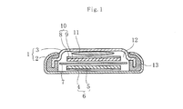
- FIG. 1 is a cross-sectional view showing a coin-type secondary battery as an embodiment of a secondary battery according to the present invention.
- the battery can 1 has a positive electrode case 2 and a negative electrode case 3, and both the positive electrode case 2 and the negative electrode case 3 are formed in a disk-like thin plate shape.
- a positive electrode current collector 4 is disposed at the center of the bottom of the positive electrode case 2, and a positive electrode active material (active material layer) 5 is formed on the surface of the positive electrode current collector 4.
- the positive electrode current collector 4 constitute a positive electrode (electrode) 6.
- a separator 7 formed of a porous film such as polypropylene is laminated on the positive electrode 6, and a negative electrode 10 having a negative electrode current collector 8 and a negative electrode active material 9 is further laminated on the separator 7.
- the negative electrode active material 9 for example, a material obtained by superimposing a lithium metal foil on Cu or a material obtained by applying a lithium storage material such as graphite or hard carbon to the metal foil can be used.
- the negative electrode current collector 8 is made of a metal material such as Cu.
- a metal spring 11 is seated on the negative electrode 10, and an electrolyte 12 is injected into the internal space, and the negative electrode case 3 is fixed to the positive electrode case 2 against the urging force of the metal spring 11, It is sealed via a gasket 13.
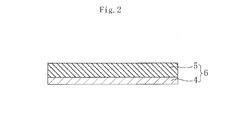
- FIG. 2 is an enlarged cross-sectional view of the positive electrode 6.
- the positive electrode active material layer 5 is formed on the surface of the positive electrode current collector 4 as described above.
- the positive electrode current collector 4 is formed of a metal foil containing a valve metal, and the surface of the positive electrode current collector 4 is subjected to an alkali treatment to form an oxide film formation site and an oxide film. And a non-oxidized film forming part.
- the valve metal is not particularly limited as long as it has a valve action, and an oxide film formation site and an oxide film non-formation site can be obtained by alkali treatment.
- Al, Ta, Ti, Nb, Zr and alloys containing these can be used, and among these, Al and Ta can be particularly preferably used.
- the distribution state of the oxide film formation site and the oxide film non-formation site and the ratio of both are not particularly limited. That is, it is considered that a mottled pattern is preferable in order to obtain a desired anchor effect, but the desired effect is sufficiently obtained if at least 0.1% or more of an oxide film forming site is present in the positive electrode current collector 4. Seems to be able to.
- the positive electrode active material layer 5 is mainly composed of an organic compound and contains an appropriate amount of a conductive agent, a binder, and the like.
- the positive electrode 6 includes the positive electrode current collector 4 and the positive electrode active material layer 5 formed on the surface of the positive electrode current collector 4, and the positive electrode active material layer 5 is mainly composed of an organic compound.
- the positive electrode current collector 4 is formed of a metal foil containing a valve action metal, and the surface of the metal foil has an oxide film formation site and an oxide film non-formation site.
- the electric body 4 and the positive electrode active material layer 5 are entangled and firmly bonded to each other, and a so-called anchor effect is exhibited.
- the adhesion between the positive electrode current collector 4 and the positive electrode active material layer 5 is improved, thereby making it possible to reduce the internal resistance, and the positive electrode active material layer 5 is mainly composed of an organic compound.
- an electrode capable of charge / discharge reaction with a large current can be obtained.
- the positive electrode active material layer 5 mainly composed of an organic compound can be charged and discharged with a large current, it can maintain a high output even after repeated charging and discharging, and has a long cycle life with a good cycle characteristic.
- a secondary battery can be obtained.
- the adhesion between the positive electrode current collector 4 and the positive electrode active material layer 5 is improved as described above, the interfacial separation between the positive electrode current collector 4 and the positive electrode active material layer 5 is minimized as long as charge and discharge are repeated. Therefore, a secondary battery with improved cycle life can be obtained.
- FIG. 3 is a charge / discharge curve showing an example of the battery characteristics of the secondary battery.
- the horizontal axis represents capacity density (mAh / g)
- the vertical axis represents voltage (V).
- a secondary battery normally, as shown in FIG. 3, when charging is started, the voltage rapidly rises to the vicinity of the specific voltage V, and the voltage becomes a substantially constant value in the vicinity of the specific voltage V. As part A is formed and the end of charging approaches, the voltage suddenly rises again. Further, when the discharge is started, the voltage rapidly decreases to the vicinity of the specific voltage V, the voltage becomes a substantially constant value near the specific voltage V to form the voltage flat portion A ′, and when the end of the discharge approaches. The voltage drops rapidly again.
- the main body of the positive electrode active material layer 5 is formed of an organic compound
- the gradient at the time of transition from the charge / discharge start to the voltage flat portions A and A ′ and The gradient at the time of transition from the voltage flat portions A and A ′ to the end of charging / discharging is small, and it is difficult to monitor the charging / discharging state of the voltage in the charging / discharging curve. Therefore, conventionally, the charge / discharge state of the secondary battery has to be confirmed by measuring the amount of electric charge.
- organic compound that is the main component of the positive electrode active material layer 5 it is preferable to use an organic radical compound containing a stable radical group, a rubeanic acid compound having a rubeanic acid structure, or a dione compound having a dione structure.
- organic radical compounds can rapidly advance the charge / discharge reaction.
- the organic radical compound has a radical which is an unpaired electron in the outermost shell of the electron orbit.
- These radicals are generally highly reactive chemical species, and many of them disappear with a certain lifetime due to interaction with surrounding substances, but they are stable depending on the state of resonance effect, steric hindrance, and solvation. It becomes a stable radical that exists stably for a long time.
- a nitroxyl radical group As a stable radical group contained in such an organic radical compound, a nitroxyl radical group, a nitrogen radical group, an oxygen radical group, a thioaminyl radical group, a sulfur radical group, a boron radical group, etc. can be used.
- a nitroxyl radical group represented by the general formula (1) is preferable.
- the following chemical reaction formula (I) shows an example of a charge / discharge reaction expected when a nitroxyl radical compound containing a nitroxyl radical group is used as an electrode active material and Li is used as a cation of an electrolyte salt. ing.
- a compound containing a 2,2,6,6-tetramethylpiperidine-N-oxyl radical structure represented by the general formula (2) in the molecular structure has a stable charge / discharge reaction. It is particularly preferable because it proceeds.
- Examples of the organic compound included in the category of the chemical formula (2) include those represented by the chemical formulas (2a) to (2f) and copolymers having these as a part of the repeating unit.
- n is an integer of 1 or more
- R 1 and R 2 are a hydrogen atom, a substituted or unsubstituted imino group, a substituted or unsubstituted alkylene group, a substituted or unsubstituted arylene group. And at least one of R 1 and R 2 includes the same case.
- the following chemical reaction formula (II) shows an example of a charge / discharge reaction expected when a rubeanic acid compound is used as an electrode active material and Li is used as a cation of an electrolyte salt.
- the rubeanic acid compound is excellent in stability during charge and discharge (oxidized state and reduced state), a multi-electron reaction of two or more electrons is possible by a redox reaction. Thereby, a secondary battery having a high capacity density can be obtained.
- Examples of the organic compound included in the category of the general formula (3) include those represented by the chemical formulas (3a) to (3c) and copolymers having these as a part of the repeating unit.
- the following chemical reaction formula (III) shows an example of a charge / discharge reaction expected when a dione compound is used as an electrode active material and Li is used as a cation for obtaining an electrolyte.
- the dione compound is also excellent in stability in the oxidation state and the reduction state, and therefore, a multi-electron reaction of two or more electrons is possible by the oxidation-reduction reaction.
- a secondary battery can be obtained.
- the compounds represented by the general formulas (4A) and (4B) are particularly preferable because they exhibit a more stable oxidation-reduction reaction, contribute to realization of a multi-electron reaction, and can be densified. .
- At least two or more of X 1 to X 4 and at least two of X 5 to X 8 are oxygen atoms, Y, Z, R 3 to R 10 , and the above X 1 to X 8 other than the oxygen atom are hydrogen atom, hydroxyl group, substituted or unsubstituted alkyl group, substituted or unsubstituted aryl group, substituted or unsubstituted aralkyl group, substituted or unsubstituted cycloalkyl group, substituted Or an unsubstituted alkoxyl group, a substituted or unsubstituted alkenyl group, a substituted or unsubstituted aryloxy group, a substituted or unsubstituted arylamino group, a substituted or unsubstituted alkylamino group, a substituted or unsubstituted thioaryl group, Substituted or unsubstituted thio
- X 1 to X 4 in the general formula (4A) and X 5 to X 8 in the general formula (4B) are each two or more of oxygen atoms as described above, and the others are optional substitutions described above.
- a group can be used, but the other part preferably has a low molecular weight because a desired battery characteristic is exhibited in the dione structure part, and a hydrogen atom is preferred from this viewpoint.
- Examples of the organic compound included in the category of the general formula (4A) include those represented by the chemical formulas (4A 1 ) and (4A 2 ) and copolymers having these as a part of the repeating unit.
- Examples of the organic compound included in the category of the general formula (4B) include those represented by the chemical formulas (4B 1 ) and (4B 2 ) and copolymers having these as a part of the repeating unit.
- the positive electrode active material is reversibly oxidized or reduced by charge / discharge, so that it is in a charged state, a discharged state, or a halfway state.
- the positive electrode active material includes at least a reaction starting material in the discharge reaction (a material that causes a chemical reaction in the battery electrode reaction), a product (a material that is generated as a result of the chemical reaction), And any of the intermediate products.
- the positive electrode active material is mainly composed of an organic compound, a secondary battery with low environmental impact and safety can be obtained.
- the above-described positive electrode active material 5 mainly composed of an organic compound is mixed with a conductive agent and a binder, and sodium hydroxide, phosphoric acid, boron, and an organic solvent and pure water are mixed so that the pH is 8-11.
- An active material paste is prepared by adding a pH adjusting agent such as acid or carbonic acid.
- pH of an active material paste is measured with a pH meter or pH test paper, and pH is controlled to the above-mentioned range.
- the conductive agent is not particularly limited, for example, carbonaceous fine particles such as graphite, carbon black, acetylene black, carbon fibers such as vapor grown carbon fiber, carbon nanotube, carbon nanohorn, polyaniline, polypyrrole, Conductive polymers such as polythiophene, polyacetylene, and polyacene can be used. Further, two or more kinds of conductive agents can be mixed and used.
- the content of the conductive agent in the positive electrode active material 5 is preferably 10 to 80% by mass.
- the binder is not particularly limited, such as polyethylene, polypropylene, polyvinylidene fluoride, polyhexafluoropropylene, polytetrafluoroethylene, polyethylene oxide, carboxymethyl cellulose, styrene butadiene copolymer, polymethyl acrylate, etc.
- Various resins can be used alone or in combination of two or more.
- the organic solvent contained in the active material paste is not particularly limited.
- bases such as dimethyl sulfoxide, dimethylformamide, N-methyl-2-pyrrolidone, propylene carbonate, diethyl carbonate, dimethyl carbonate, and ⁇ -butyrolactone are used.
- An organic solvent such as an organic solvent, a non-aqueous solvent such as acetonitrile, tetrahydrofuran, nitrobenzene, and acetone, and a protic solvent such as methanol and ethanol can be used.
- the content of the organic solvent in the active material paste is usually 99% by mass or less.
- the active material paste thus adjusted to a pH of 8 to 11 is coated on a metal foil made of a valve metal such as Al by an arbitrary coating method, whereby an alkali treatment is applied to the surface of the metal foil. Is applied to form an oxide film formation site and an oxide film non-formation site. Thereafter, the positive electrode 6 having the positive electrode active material 5 formed on the surface of the positive electrode current collector 4 is produced by drying for a predetermined time.
- the electrolyte 12 is prepared.
- the electrolyte 12 is interposed between the positive electrode 6 and the negative electrode 10 which is the opposite electrode of the positive electrode 6 to transport charge carriers between both electrodes.
- an electrolyte 12 for example, 10 ⁇ 5 at room temperature.
- a material having an ionic conductivity of ⁇ 10 ⁇ 1 S / cm is used, and an electrolyte salt dissolved in an organic solvent is used.
- electrolyte salt for example, LiPF 6 , LiClO 4 , LiBF 4 , LiCF 3 SO 3 , LiN (CF 3 SO 2 ) 2 , LiN (C 2 F 5 SO 2 ) 2 , LiC (CF 3 SO 2 ) 3 , LiC (C 2 F 5 SO 2 ) 3 and the like.
- Examples of the organic solvent contained in the electrolyte 12 include ethylene carbonate, propylene carbonate, dimethyl carbonate, diethyl carbonate, methyl ethyl carbonate, ⁇ -butyrolactone, tetrahydrofuran, dioxolane, sulfolane, dimethylformamide, dimethylacetamide, and N-methyl-2.
- -Pyrrolidone or the like can be used.
- the type of organic solvent, the compounding ratio of the organic compound and the organic solvent, the type of additive and the amount added, etc. should be set arbitrarily in consideration of the required characteristics and productivity of the secondary battery. Can do.
- the positive electrode 6 is impregnated in the electrolyte 12, and the negative electrode 10 is disposed so as to face the positive electrode 6 through the separator 7 impregnated with the electrolyte 12, and then the electrolyte 9 is injected into the internal space.
- a metal spring 11 is seated on the negative electrode 10 and a gasket 13 is arranged on the periphery, and the negative electrode case 3 is fixed to the positive electrode case 2 with a caulking machine or the like, and is externally sealed, thereby a coin-type secondary battery. Is produced.
- a solvent and a pH adjuster are added to an active material raw material mainly composed of an organic compound to produce an active material paste having a pH adjusted to 8 to 11, and a valve action metal is contained.
- An active material paste is applied to the surface of the metal foil, and the metal foil is subjected to alkali treatment to form an oxide film formation site and an oxide film non-formation site on the surface of the metal foil. Since the positive electrode active material layer 5 is formed on the surface of the metal foil, an oxide film formation site and an oxide film non-formation site are formed on the surface of the metal foil by the alkali treatment. Therefore, the positive electrode current collector 4 and the positive electrode are formed by the so-called anchor effect. The adhesion of the active material layer 5 is improved, and an electrode having a small internal resistance and capable of charge / discharge reaction with a large current can be easily produced.
- the present invention is not limited to the above-described embodiment, and various modifications can be made without departing from the scope of the invention.
- the above-listed compounds are merely examples, and are not limited thereto. That is, if the positive electrode active material layer 5 is mainly composed of an organic compound, it is considered that a desired oxidation-reduction reaction proceeds stably, so that cycle characteristics that can maintain high output even after repeated charge and discharge are performed. A secondary battery having a good long cycle life can be obtained.
- the electrolytic solution is used for the electrolyte 12, but a solid electrolyte may be used.
- the polymer compound used in the solid electrolyte include polyvinylidene fluoride, vinylidene fluoride-hexafluoropropylene copolymer, vinylidene fluoride-ethylene copolymer, vinylidene fluoride-monofluoroethylene copolymer, fluoride Vinylidene fluoride polymers such as vinylidene-trifluoroethylene copolymer, vinylidene fluoride-tetrafluoroethylene copolymer, vinylidene fluoride-hexafluoropropylene-tetrafluoroethylene terpolymer, and acrylonitrile-methyl methacrylate copolymer Polymer, acrylonitrile-methyl acrylate copolymer, acrylonitrile-ethyl methacrylate copolymer, acrylonitrile-ethyl
- the electrode of the present invention is used for the positive electrode, but it is also useful to use it for the negative electrode.
- the coin-type secondary battery has been described.
- the battery shape is not particularly limited, and can be applied to a cylindrical type, a square type, a sheet type, and the like.
- the exterior method is not particularly limited, and a metal case, mold resin, aluminum laminate film, or the like may be used.
- Example shown below is an example and this invention is not limited to the following Example.
- PTMA 600 mg
- carbon black having an average particle size of 36 nm as a conductive agent (Denka Black Press product manufactured by Denki Kagaku Kogyo Co., Ltd.): 300 mg
- polyvinylidene fluoride as a binder KF-1700 manufactured by Kureha
- 100 mg was weighed, N-methyl-2-pyrrolidone as an organic solvent was added to these weighed products, and the mixture was stirred at room temperature for 30 minutes using a homomixer to obtain a slurry.
- a sodium hydroxide solution was added to the slurry to prepare an active material paste having a pH adjusted to 9.0. The pH of the active material paste was measured with a pH meter.
- an active material paste was applied onto a positive electrode current collector made of an Al foil having a thickness of 20 ⁇ m and dried at 120 ° C., whereby PTMA having a thickness of 150 ⁇ m was combined with the positive electrode active material.
- a positive electrode was prepared.
- the positive electrode was punched into a circular shape having a diameter of 12 mm, and then impregnated with an electrolytic solution. After repeating pressure reduction and pressure increase twice, the positive electrode was allowed to stand at normal pressure for 30 minutes, and the electrolytic solution was infiltrated into voids in the positive electrode. . The decompression was performed for 30 seconds with a decompression ratio of 80%.
- an ethylene carbonate / diethyl carbonate mixed solution (organic solvent) containing LiPF 6 (electrolyte salt) having a molar concentration of 1.0 mol / L was used as the electrolytic solution.
- the positive electrode impregnated with the electrolytic solution in this manner is placed in the center of the bottom of the positive electrode case, and then a separator having a thickness of 20 ⁇ m made of a polypropylene porous film impregnated with the electrolytic solution is laminated on the positive electrode.
- a negative electrode active material in which lithium was applied to both sides of the foil was laminated on the separator.
- the negative electrode collector which consists of Cu was laminated
- a metal spring is seated on the negative electrode current collector, and then the negative electrode case is joined to the positive electrode case with a gasket disposed on the periphery, and the outer battery is sealed with a caulking machine.
- this battery cell was subjected to a charge / discharge test at a constant current of 30 mA, that is, a charge / discharge rate of 60C (1C is the amount of electricity until charge or discharge is completed in 1 hour).
- a charge / discharge rate of 60C (1C is the amount of electricity until charge or discharge is completed in 1 hour).
- the discharge capacity was 0.4 mAh or more, and it was found that the secondary battery can maintain a high output with little reduction in capacity even when charging / discharging with a large current.
- Example 1 [Production of battery cells] As in Example 1, PTMA is used as the organic compound, carbon black is used as the conductive agent, 120 g of an aqueous solution containing 2% by mass of carboxymethylcellulose is added as a binder, and the mixture is stirred using a rotating and rotating stirrer. After that, 2 g of a dispersion solvent in which 10% by mass of tetrafluoroethylene was dispersed as an organic solvent was added and stirred at room temperature using a homomixer to obtain a slurry. Next, after standing for 10 minutes, a sodium hydroxide solution was added to the slurry to prepare an active material paste having a pH of 9.0. The pH of the active material paste was measured with a pH meter as in Example 1.
- an active material paste is applied onto a positive electrode current collector made of an Al foil having a thickness of 20 ⁇ m, and dried at 120 ° C. to produce a positive electrode using PTMA having a thickness of 150 ⁇ m as a positive electrode active material. did.
- Example 2 Thereafter, using this positive electrode, a battery cell of Example 2 was produced by the same method and procedure as Example 1.
- a battery cell of Example 3 was produced in the same manner and procedure as in Example 1 except that rubeanic acid represented by the chemical formula (3a) was used as the positive electrode active material.
- a battery cell of Example 4 was produced in the same manner and procedure as in Example 1 except that tetraketopyracene represented by the chemical formula (4A 2 ) was used as the positive electrode active material.
Landscapes
- Chemical & Material Sciences (AREA)
- Engineering & Computer Science (AREA)
- Chemical Kinetics & Catalysis (AREA)
- Electrochemistry (AREA)
- General Chemical & Material Sciences (AREA)
- Materials Engineering (AREA)
- Manufacturing & Machinery (AREA)
- Composite Materials (AREA)
- Battery Electrode And Active Subsutance (AREA)
Abstract
A positive electrode (6) has a positive electrode collector (4) and a positive electrode active material layer (5) formed on the surface of the positive electrode collector (4). The positive electrode active material layer (5) is formed principally from organic compounds. The positive electrode collector (4) is formed from a metal foil containing a valve-action metal. The surface of the metal foil is provided with: an oxide film formation portion which is alkali-treated using an active material paste having the pH adjusted to 8 to 11, and which has an oxide film formed thereon; and an oxide film non-formation portion on which the oxide film is not formed. An organic radical compound including a stable radical group, a rubeanic acid compound having a rubeanic acid structure, and a dione compound having a dione structure are preferably used as the organic compounds. A secondary cell is obtained using the positive electrode (6) of such description. A long-cycle-life secondary cell that is capable of maintaining a high output even upon repeated charging/discharging and that has excellent cycle characteristics is thereby obtained.
Description
本発明は電極と該電極の製造方法、及び二次電池に関し、より詳しくは電極活物質の主体が有機化合物で形成された電極とその製造方法、及びこの電極を使用した二次電池に関する。
The present invention relates to an electrode, a method for manufacturing the electrode, and a secondary battery, and more particularly to an electrode in which an electrode active material is mainly formed of an organic compound, a method for manufacturing the electrode, and a secondary battery using the electrode.
携帯電話、ノートパソコン、デジタルカメラ等の携帯用電子機器の市場拡大に伴い、これら電子機器のコードレス電源としてエネルギー密度が大きく高出力化が可能で長サイクル寿命の二次電池が待望されている。
With the expansion of the market for portable electronic devices such as mobile phones, notebook PCs, and digital cameras, secondary batteries with long energy cycles and high energy density and long output life are expected as cordless power sources for these electronic devices.
そして、このような要求に応えるべく、リチウムイオン等のアルカリ金属イオンを荷電担体とし、その電荷授受に伴う電気化学反応を利用した二次電池が開発されている。特に、リチウムイオン二次電池は、エネルギー密度が大きく、車載用バッテリーとしても広く普及しつつある。
In order to meet such demands, secondary batteries using an alkali metal ion such as lithium ion as a charge carrier and utilizing an electrochemical reaction accompanying the charge transfer have been developed. In particular, lithium ion secondary batteries have a high energy density and are becoming widespread as in-vehicle batteries.
ところで、二次電池の構成要素のうち電極活物質は、充電反応、放電反応という電池電極反応に直接寄与する物質であり、二次電池の中心的役割を有する。すなわち、電池電極反応は、電解質中に配された電極と電気的に接続された電極活物質に対し電圧を印加することにより、電子の授受を伴って生じる反応であり、電池の充放電時に進行する。したがって、上述したように電極活物質は、システム的には、二次電池の中心的役割を有する。
By the way, of the constituent elements of the secondary battery, the electrode active material is a substance that directly contributes to the battery electrode reaction such as the charge reaction and the discharge reaction, and has the central role of the secondary battery. That is, the battery electrode reaction is a reaction that occurs with the transfer of electrons by applying a voltage to an electrode active material that is electrically connected to an electrode disposed in the electrolyte, and proceeds during charging and discharging of the battery. To do. Therefore, as described above, the electrode active material has a central role of the secondary battery in terms of system.
そして、上記リチウムイオン二次電池では、正極活物質としてリチウム含有遷移金属酸化物、負極活物質として炭素材料を使用し、これらの電極活物質に対するリチウムイオンの挿入反応、及び脱離反応を利用して充放電を行っている。
In the lithium ion secondary battery, a lithium-containing transition metal oxide is used as a positive electrode active material, a carbon material is used as a negative electrode active material, and an insertion reaction and a desorption reaction of lithium ions with respect to these electrode active materials are used. Charging / discharging.
しかしながら、リチウムイオン二次電池は、正極におけるリチウムイオンの移動が律速となるため、充放電の速度が制限されるという問題があった。すなわち、上述したリチウムイオン二次電池では、電解質や負極に比べて正極の遷移金属酸化物中でのリチウムイオンの移動速度が遅く、このため正極での電池反応速度が律速となって充放電速度が制限され、その結果、高出力化や充電時間の短時間化には限界があった。
However, the lithium ion secondary battery has a problem in that the speed of charging and discharging is limited because the movement of lithium ions in the positive electrode is rate limiting. That is, in the above-described lithium ion secondary battery, the migration rate of lithium ions in the transition metal oxide of the positive electrode is slower than that of the electrolyte and the negative electrode, and therefore the battery reaction rate at the positive electrode becomes the rate-determining rate. As a result, there is a limit to increasing the output and shortening the charging time.
そこで、このような課題を解決すべく、近年、有機ラジカル化合物や有機イオウ化合物を電極活物質に使用した二次電池の研究・開発が盛んに行われている。
Therefore, in order to solve such problems, research and development of secondary batteries using organic radical compounds and organic sulfur compounds as electrode active materials have been actively conducted in recent years.
例えば、有機ラジカル化合物を電極活物質に使用した先行技術文献としては、特許文献1が知られている。
For example, Patent Document 1 is known as a prior art document using an organic radical compound as an electrode active material.
この特許文献1には、ニトロキシルラジカル化合物、オキシラジカル化合物、及び窒素原子上にラジカルを有する窒素ラジカル化合物を使用した二次電池用活物質が開示されている。
Patent Document 1 discloses a secondary battery active material using a nitroxyl radical compound, an oxy radical compound, and a nitrogen radical compound having a radical on a nitrogen atom.
有機ラジカル化合物は、反応する不対電子がラジカル原子に局在化して存在するため、反応部位の濃度を増大させることができ、これにより高容量の二次電池の実現を期待することができる。また、ラジカルは反応速度が速いので、安定ラジカルの酸化還元反応を利用して充放電を行うことにより、充電時間を短時間で完了させることが可能と考えられる。
In organic radical compounds, the unpaired electrons that react are localized in the radical atoms, so that the concentration of the reaction site can be increased, and thus a high-capacity secondary battery can be realized. Further, since the reaction rate of radicals is high, it is considered that the charging time can be completed in a short time by performing charging / discharging utilizing a redox reaction of a stable radical.
そして、この特許文献1では、ラジカルとして安定性の高いニトロキシルラジカルを使用した実施例が記載されており、例えば、ニトロニルニトロキシド化合物を含む電極層を正極とし、リチウム貼り合わせ銅箔を負極とした二次電池を作製し、繰り返し充放電したところ、10サイクル以上にわたって充放電が可能であることが確認されている。
And in this patent document 1, the Example using the highly stable nitroxyl radical as a radical is described, for example, the electrode layer containing a nitronyl nitroxide compound is used as a positive electrode, and lithium bonding copper foil is used as a negative electrode. It was confirmed that charging / discharging was possible over 10 cycles or more when a secondary battery was manufactured and repeatedly charged / discharged.
また、有機イオウ化合物を電極活物質に使用した先行技術文献としては、特許文献2及び3が知られている。
Also, Patent Documents 2 and 3 are known as prior art documents using an organic sulfur compound as an electrode active material.
特許文献2には、正極材料である有機イオウ化合物が充電状態でS-S結合を有すると共に、正極の放電時にはS-S結合が開裂し、金属イオンを有する有機イオウ金属塩を形成した新規な金属-イオウ型電池セルが提案されている。
Patent Document 2 discloses a novel organic sulfur compound, which is a positive electrode material, has an SS bond in a charged state, and the SS bond is cleaved during discharge of the positive electrode to form an organic sulfur metal salt having a metal ion. Metal-sulfur battery cells have been proposed.
この特許文献2では、有機イオウ化合物として、一般式(1′)で表されるジスルフィド系の有機化合物(以下、「ジスルフィド化合物」という。)を使用している。
In this Patent Document 2, a disulfide organic compound represented by the general formula (1 ′) (hereinafter referred to as “disulfide compound”) is used as the organic sulfur compound.
R-S-S-R … (1′)
RSSR ... (1 ')
ここで、Rは脂肪族有機基又は芳香族有機基を示し、各々は同一又は異なる場合を含んでいる。
Here, R represents an aliphatic organic group or an aromatic organic group, and each includes the same or different cases.
ジスルフィド化合物は、2電子反応が可能であり、還元状態(放電状態)でS-S結合が開裂し、これにより有機チオレート(R-SH)を形成する。そして、この有機チオレートは酸化状態(充電状態)でS-S結合を形成し、一般式(1′)で示すジスルフィド化合物に復元する。つまり、ジスルフィド化合物は結合エネルギーの小さなS-S結合を形成するため、反応による結合と開裂を利用して可逆的な酸化還元反応が生じ、これにより充放電を行うことができる。
The disulfide compound can undergo a two-electron reaction, and the S—S bond is cleaved in a reduced state (discharge state), thereby forming an organic thiolate (R—SH). This organic thiolate forms an S—S bond in the oxidized state (charged state) and is restored to the disulfide compound represented by the general formula (1 ′). In other words, since the disulfide compound forms an SS bond having a small binding energy, a reversible redox reaction occurs using the bond and cleavage by the reaction, and thus charge and discharge can be performed.
また、特許文献3には、次式(2′):
-(NH-CS-CS-NH)…(2′)
で示される構造単位を有し、リチウムイオンと結合可能なルベアン酸やルベアン酸ポリマーを含む電池用電極が提案されている。Patent Document 3 discloses the following formula (2 ′):
-(NH-CS-CS-NH) (2 ')
There has been proposed a battery electrode containing rubeanic acid or rubeanic acid polymer which has a structural unit represented by
-(NH-CS-CS-NH)…(2′)
で示される構造単位を有し、リチウムイオンと結合可能なルベアン酸やルベアン酸ポリマーを含む電池用電極が提案されている。
-(NH-CS-CS-NH) (2 ')
There has been proposed a battery electrode containing rubeanic acid or rubeanic acid polymer which has a structural unit represented by
一般式(2′)で表されるジチオン構造を含有したルベアン酸やルベアン酸ポリマーは、還元時にリチウムイオンと結合し、酸化時に前記結合したリチウムイオンを放出する。このようなルベアン酸又はルベアン酸ポリマーの可逆的な酸化還元反応を利用することによって充放電を行うことができる。
The rubeanic acid or rubeanic acid polymer containing a dithione structure represented by the general formula (2 ′) binds to lithium ions during reduction, and releases the bound lithium ions during oxidation. Charging / discharging can be performed by utilizing such a reversible oxidation-reduction reaction of rubeanic acid or rubeanic acid polymer.
この特許文献3では、正極活物質にルベアン酸を使用した場合、二電子反応が可能であり、常温で400Ah/kgの容量密度を有する二次電池を得ている。
In Patent Document 3, when rubeanic acid is used as the positive electrode active material, a two-electron reaction is possible, and a secondary battery having a capacity density of 400 Ah / kg at room temperature is obtained.
一方、二次電池の電極としては、例えば、電極活物質を含有した活物質ペーストを作製し、該活物質ペーストをAl等の耐酸性皮膜を有する金属箔からなる電極集電体に塗工し、電極集電体の表面に電極活物質層を形成したものが知られている。
On the other hand, as an electrode of a secondary battery, for example, an active material paste containing an electrode active material is prepared, and the active material paste is applied to an electrode current collector made of a metal foil having an acid-resistant film such as Al. In addition, a material in which an electrode active material layer is formed on the surface of an electrode current collector is known.
そして、この種の電極の作製方法としては、電極集電体がアルカリ等で腐食されるのを抑制する観点から、活物質ペーストを酸性に保持したり、非水系溶剤を使用する方法が知られている。
As a method for producing this type of electrode, a method of keeping the active material paste acidic or using a non-aqueous solvent is known from the viewpoint of suppressing the electrode current collector from being corroded by alkali or the like. ing.
例えば、特許文献4には、一般式Li[Lix(NiyM1-y)1-x]O2(ただし、xは0.01~0.10、yは0.5~0.8、MはCo、Mn、Al、Mg、Ti、Fe、Cr,Si,Zrから選ばれる少なくとも1種の元素)で表される非水電解質二次電池用正極活物質の製造方法であって、前記正極活物質をpHが3.0~6.0の酸性溶液を用いて中和処理した後、水洗により中和生成物を除去するようにした非水電解質二次電池用正極活物質の製造方法が提案されている。
For example, Patent Document 4 discloses a general formula Li [Li x (Ni y M 1-y ) 1-x ] O 2 (where x is 0.01 to 0.10 and y is 0.5 to 0.8). , M is at least one element selected from Co, Mn, Al, Mg, Ti, Fe, Cr, Si, Zr), and a method for producing a positive electrode active material for a non-aqueous electrolyte secondary battery, Production of a positive electrode active material for a non-aqueous electrolyte secondary battery, wherein the positive electrode active material is neutralized using an acidic solution having a pH of 3.0 to 6.0, and then the neutralized product is removed by washing with water. A method has been proposed.
この特許文献4は、正極活物質の表面に存在するアルカリ成分を除去することにより、正極集電体であるAl箔の腐食を抑制しようとしている。
This Patent Document 4 attempts to suppress the corrosion of the Al foil, which is a positive electrode current collector, by removing the alkaline component present on the surface of the positive electrode active material.
また、特許文献5には、アルカリにより腐食し得る金属箔集電体に、アルカリ性の活物質ペーストを用いて活物質層が形成された電極を備える二次電池の製造方法であって、前記電極を形成する電極形成工程を備え、前記電極形成工程は、前記金属箔集電体に前記活物質ペーストを塗工する塗工工程と、前記金属箔集電体に塗工された前記活物質ペーストを乾燥させる乾燥工程と、前記塗工工程後、前記乾燥工程の直前までの間、前記金属箔集電体を12℃以下の低温に保つ低温保持工程とを有する二次電池の製造方法が提案されている。
Further, Patent Document 5 discloses a method for manufacturing a secondary battery comprising an electrode in which an active material layer is formed using an alkaline active material paste on a metal foil current collector that can be corroded by an alkali. The electrode forming step includes: an application step of applying the active material paste to the metal foil current collector; and the active material paste applied to the metal foil current collector. Proposing a method for producing a secondary battery, comprising: a drying step for drying the metal foil; and a low-temperature holding step for keeping the metal foil current collector at a low temperature of 12 ° C. or lower between the coating step and immediately before the drying step. Has been.
この特許文献5では、金属箔集電体に活物質ペーストを塗工した後、該活物質ペーストを乾燥させるまでの間、金属箔集電体を12℃以下の低温に保つことにより、塗工工程から乾燥工程の直前までの期間中に、活物質ペーストのアルカリと金属箔集電体との反応をし難くし、これによりアルカリにより金属箔集電体が腐食するのを抑制し、金属箔集電体上に電気絶縁性の皮膜が形成されるのを抑制しようとしている。
In this patent document 5, after applying an active material paste to a metal foil current collector, the metal foil current collector is kept at a low temperature of 12 ° C. or lower until the active material paste is dried. During the period from the process to just before the drying process, it is difficult for the alkali of the active material paste to react with the metal foil current collector, thereby preventing the metal foil current collector from corroding by the alkali, and the metal foil An attempt is made to suppress the formation of an electrically insulating film on the current collector.
特許文献1~3では、電極活物質として特定の有機化合物を使用することにより、高容量で高出力の二次電池が実現可能であり、これら有機化合物を電極活物質に使用した場合の有用性について記載されている。
In Patent Documents 1 to 3, by using a specific organic compound as an electrode active material, a secondary battery having a high capacity and a high output can be realized, and usefulness when these organic compounds are used as an electrode active material. Is described.
このように特定の有機化合物を電極活物質に使用することにより、大電流で充放電を行うことは可能であるが、そのためには電極の内部抵抗を小さくすることが要請される。
In this way, by using a specific organic compound as an electrode active material, it is possible to charge and discharge with a large current, but for that purpose, it is required to reduce the internal resistance of the electrode.
しかしながら、特許文献4や特許文献5では、正極活物質を酸性処理したり、活物質ペーストの塗工後に金属箔集電体を低温で保持することにより、電極形成時に生じる金属箔集電体の腐食を抑制しようとしたものであり、電極の内部抵抗を低下させようとしたものではなく、また、電極活物質に有機化合物を使用したものでもない。
However, in Patent Document 4 and Patent Document 5, the positive electrode active material is subjected to an acid treatment, or the metal foil current collector is maintained at a low temperature after the application of the active material paste, whereby the metal foil current collector generated at the time of electrode formation. It is intended to suppress corrosion and is not intended to reduce the internal resistance of the electrode, nor is an organic compound used as the electrode active material.
このように従来では、電極の内部抵抗を十分に小さくしようとしたものが存在せず、大電流で充放電が可能な有機化合物を電極活物質に使用しても、未だ有機化合物の特性を十分に発揮させた二次電池を実現できていない状況にある。
Thus, there has been no conventional attempt to sufficiently reduce the internal resistance of the electrode, and even if an organic compound that can be charged and discharged with a large current is used as the electrode active material, the characteristics of the organic compound are still sufficient. The secondary battery demonstrated in Fig. 1 cannot be realized.
本発明はこのような事情に鑑みてなされたものであって、充放電を繰り返しても高出力が維持可能でサイクル特性の良好な長サイクル寿命の二次電池を得ることができる電極とその製造方法、及びこれを使用した二次電池とその製造方法を提供することを目的とする。
The present invention has been made in view of such circumstances, and an electrode capable of maintaining a high output even after repeated charge and discharge and capable of obtaining a secondary battery with good cycle characteristics and a long cycle life, and its manufacture It is an object to provide a method, a secondary battery using the method, and a manufacturing method thereof.
本発明者らは、上記目的を達成するために鋭意研究を行ったところ、弁作用金属を含有した金属箔からなる集電体にアルカリ処理を施し、集電体の表面が、酸化皮膜が形成された酸化皮膜形成部位と前記酸化皮膜が形成されていない酸化皮膜非形成部位とを有することにより、活物質層と集電体との密着性が向上し、これにより内部抵抗を低下させることができ、その結果、充放電を繰り返しても高出力を維持することができるサイクル特性の良好な二次電池用の電極を得ることができるという知見を得た。
The inventors of the present invention have made extensive studies to achieve the above-mentioned object. As a result, the current collector made of a metal foil containing a valve metal is subjected to an alkali treatment, and an oxide film is formed on the surface of the current collector. By having the oxidized film forming site and the oxidized film non-formed site where the oxide film is not formed, the adhesion between the active material layer and the current collector is improved, thereby reducing the internal resistance. As a result, it was found that an electrode for a secondary battery having good cycle characteristics capable of maintaining a high output even after repeated charge and discharge can be obtained.
本発明はこのような知見に基づきなされたものであって、本発明に係る電極は、集電体と、該集電体の表面に形成された活物質層とを有し、前記活物質層は、有機化合物を主体とすると共に、前記集電体が、弁作用金属を含有した金属箔で形成され、前記金属箔の表面は、酸化皮膜が形成された酸化皮膜形成部位と前記酸化皮膜が形成されていない酸化皮膜非形成部位とを有していることを特徴としている。
The present invention has been made based on such knowledge, and the electrode according to the present invention includes a current collector and an active material layer formed on the surface of the current collector, and the active material layer Is mainly composed of an organic compound, and the current collector is formed of a metal foil containing a valve action metal, and the surface of the metal foil is formed of an oxide film forming site on which an oxide film is formed and the oxide film. It is characterized by having an oxide film non-formation part which is not formed.
また、本発明の電極は、前記金属箔は、アルカリ処理がなされているのが好ましい。
In the electrode of the present invention, the metal foil is preferably subjected to alkali treatment.
さらに、本発明の電極は、前記有機化合物が、安定ラジカル基を含有した有機ラジカル化合物、ルベアン酸構造を有するルベアン酸化合物、及びジオン構造を有するジオン化合物のうちの少なくとも1種を含むのが好ましい。
Further, in the electrode of the present invention, the organic compound preferably contains at least one of an organic radical compound containing a stable radical group, a rubeanic acid compound having a rubeanic acid structure, and a dione compound having a dione structure. .
また、本発明の電極は、前記有機ラジカル化合物が、ニトロキシルラジカル系化合物であるのが好ましい。
In the electrode of the present invention, the organic radical compound is preferably a nitroxyl radical compound.
さらに、本発明の電極は、前記ニトロキシルラジカル系化合物が、2,2,6,6-テトラメチルピペリジン-N-オキシルラジカルを分子構造中に含んでいるのが好ましい。
Furthermore, in the electrode of the present invention, the nitroxyl radical compound preferably contains 2,2,6,6-tetramethylpiperidine-N-oxyl radical in the molecular structure.
また、本発明の電極は、前記ルベアン酸化合物が、一般式
Further, in the electrode of the present invention, the rubeanic acid compound has the general formula

で表わされるのが好ましい。
It is preferable to be represented by.
ここで、式中、nは1以上の整数であり、R1及びR2は、水素原子、置換若しくは無置換のイミノ基、置換若しくは無置換のアルキレン基、置換若しくは無置換のアリーレン基のうちの少なくともいずれか1種を示し、R1及びR2は同一の場合を含んでいる。
In the formula, n is an integer of 1 or more, and R 1 and R 2 are a hydrogen atom, a substituted or unsubstituted imino group, a substituted or unsubstituted alkylene group, a substituted or unsubstituted arylene group. And at least one of R 1 and R 2 includes the same case.
また、本発明の電極は、前記ジオン化合物が、一般式
In the electrode of the present invention, the dione compound has the general formula

で表わされるのが好ましい。
It is preferable to be represented by.
ここで、式中、X1~X4のうちの少なくとも2つ以上が酸素原子であり、R3~R6、及び前記酸素原子以外のX1~X4は、水素原子、水酸基、置換若しくは無置換のアルキル基、置換若しくは無置換のアリール基、置換若しくは無置換のアラルキル基、置換若しくは無置換のシクロアルキル基、置換若しくは無置換のアルコキシル基、置換若しくは無置換のアルケニル基、置換若しくは無置換のアリールオキシ基、置換若しくは無置換のアリールアミノ基、置換若しくは無置換のアルキルアミノ基、置換若しくは無置換のチオアリール基、置換若しくは無置換のチオアルキル基、置換若しくは無置換の複素環基、置換若しくは無置換のホルミル基、置換若しくは無置換のシリル基、置換若しくは無置換のボリル基、置換若しくは無置換のスタンニル基、置換若しくは無置換のシアノ基、置換若しくは無置換のニトロ基、置換若しくは無置換のニトロソ基、置換若しくは無置換のアミノ基、置換若しくは無置換のイミノ基、置換若しくは無置換のカルボキシル基、置換若しくは無置換のアルコキシカルボニル基、ハロゲン原子、置換若しくは無置換のエステル、置換若しくは無置換のチオエステル、置換若しくは無置換のエーテル、置換若しくは無置換のチオエーテル、置換若しくは無置換のアミン、置換若しくは無置換のアミド、置換若しくは無置換のスルホン、置換若しくは無置換のチオスルホニル、置換若しくは無置換のスルホンアミド、置換若しくは無置換のイミン、置換若しくは無置換のアゾ基のうちの少なくともいずれか1種を示し、これらR3~R6及びX1~X4は同一の場合を含み、互いに連結して飽和若しくは不飽和の環を形成する場合を含んでいる。
Here, in the formula, at least two of X 1 to X 4 are oxygen atoms, and R 3 to R 6 and X 1 to X 4 other than the oxygen atoms are hydrogen atoms, hydroxyl groups, substituted or Unsubstituted alkyl group, substituted or unsubstituted aryl group, substituted or unsubstituted aralkyl group, substituted or unsubstituted cycloalkyl group, substituted or unsubstituted alkoxyl group, substituted or unsubstituted alkenyl group, substituted or unsubstituted Substituted aryloxy group, substituted or unsubstituted arylamino group, substituted or unsubstituted alkylamino group, substituted or unsubstituted thioaryl group, substituted or unsubstituted thioalkyl group, substituted or unsubstituted heterocyclic group, substituted Or an unsubstituted formyl group, a substituted or unsubstituted silyl group, a substituted or unsubstituted boryl group, substituted or Unsubstituted stannyl group, substituted or unsubstituted cyano group, substituted or unsubstituted nitro group, substituted or unsubstituted nitroso group, substituted or unsubstituted amino group, substituted or unsubstituted imino group, substituted or unsubstituted Carboxyl group, substituted or unsubstituted alkoxycarbonyl group, halogen atom, substituted or unsubstituted ester, substituted or unsubstituted thioester, substituted or unsubstituted ether, substituted or unsubstituted thioether, substituted or unsubstituted amine , Substituted or unsubstituted amide, substituted or unsubstituted sulfone, substituted or unsubstituted thiosulfonyl, substituted or unsubstituted sulfonamide, substituted or unsubstituted imine, substituted or unsubstituted azo group one kind and any two of R 3 ~ R 6及X 1 ~ X 4 includes a case identical and includes a case of forming a saturated or unsaturated linked each other to form a ring.
また、本発明の電極は、前記ジオン化合物が、一般式
In the electrode of the present invention, the dione compound has the general formula

で表わされるのも好ましい。
It is also preferable to be represented by.
ここで、式中、X5~X8のうちの少なくとも2つ以上が酸素原子であり、Y、Z、R7~R10、及び前記酸素原子以外のX5~X8は、水素原子、水酸基、置換若しくは無置換のアルキル基、置換若しくは無置換のアリール基、置換若しくは無置換のアラルキル基、置換若しくは無置換のシクロアルキル基、置換若しくは無置換のアルコキシル基、置換若しくは無置換のアルケニル基、置換若しくは無置換のアリールオキシ基、置換若しくは無置換のアリールアミノ基、置換若しくは無置換のアルキルアミノ基、置換若しくは無置換のチオアリール基、置換若しくは無置換のチオアルキル基、置換若しくは無置換の複素環基、置換若しくは無置換のホルミル基、置換若しくは無置換のシリル基、置換若しくは無置換のボリル基、置換若しくは無置換のスタンニル基、置換若しくは無置換のシアノ基、置換若しくは無置換のニトロ基、置換若しくは無置換のニトロソ基、置換若しくは無置換のアミノ基、置換若しくは無置換のイミノ基、置換若しくは無置換のカルボキシル基、置換若しくは無置換のアルコキシカルボニル基、ハロゲン原子、置換若しくは無置換のエステル、置換若しくは無置換のチオエステル、置換若しくは無置換のエーテル、置換若しくは無置換のチオエーテル、置換若しくは無置換のアミン、置換若しくは無置換のアミド、置換若しくは無置換のスルホン、置換若しくは無置換のチオスルホニル、置換若しくは無置換のスルホンアミド、置換若しくは無置換のイミン、置換若しくは無置換のアゾ基のうちの少なくともいずれか1種を示し、Y、Z、R7~R10及びX5~X8は同一の場合を含み、互いに連結して飽和若しくは不飽和の環を形成する場合を含んでいる。
Here, in the formula, at least two of X 5 to X 8 are oxygen atoms, and Y, Z, R 7 to R 10 , and X 5 to X 8 other than the oxygen atoms are hydrogen atoms, Hydroxyl group, substituted or unsubstituted alkyl group, substituted or unsubstituted aryl group, substituted or unsubstituted aralkyl group, substituted or unsubstituted cycloalkyl group, substituted or unsubstituted alkoxyl group, substituted or unsubstituted alkenyl group Substituted or unsubstituted aryloxy group, substituted or unsubstituted arylamino group, substituted or unsubstituted alkylamino group, substituted or unsubstituted thioaryl group, substituted or unsubstituted thioalkyl group, substituted or unsubstituted complex Cyclic group, substituted or unsubstituted formyl group, substituted or unsubstituted silyl group, substituted or unsubstituted boryl group, substituted Or an unsubstituted stannyl group, a substituted or unsubstituted cyano group, a substituted or unsubstituted nitro group, a substituted or unsubstituted nitroso group, a substituted or unsubstituted amino group, a substituted or unsubstituted imino group, substituted or Unsubstituted carboxyl group, substituted or unsubstituted alkoxycarbonyl group, halogen atom, substituted or unsubstituted ester, substituted or unsubstituted thioester, substituted or unsubstituted ether, substituted or unsubstituted thioether, substituted or unsubstituted Of the amine, substituted or unsubstituted amide, substituted or unsubstituted sulfone, substituted or unsubstituted thiosulfonyl, substituted or unsubstituted sulfonamido, substituted or unsubstituted imine, substituted or unsubstituted azo group At least one of them is shown, Y, Z, R 7 -R 10 and X 5 -X 8 include the same case, and include the case where they are connected to each other to form a saturated or unsaturated ring.
また、本発明に係る電極の製造方法は、有機化合物を主体とした活物質原料に溶剤及びpH調整剤を添加し、pHが8~11に調製された活物質ペーストを作製し、弁作用金属を含有した金属箔の表面に前記活物質ペーストを塗工し、前記金属箔にアルカリ処理を施して酸化皮膜が形成された酸化皮膜形成部位と前記酸化皮膜が形成されていない酸化皮膜非形成部位とを前記金属箔の表面に形成し、集電体である前記金属箔の表面に活物質層を形成することを特徴としている。
In addition, the electrode manufacturing method according to the present invention includes adding a solvent and a pH adjuster to an active material raw material mainly composed of an organic compound to produce an active material paste having a pH adjusted to 8 to 11, thereby producing a valve action metal. The active material paste is coated on the surface of the metal foil containing the metal foil, the oxide film is formed by applying an alkali treatment to the metal foil, and the oxide film non-forming part where the oxide film is not formed Are formed on the surface of the metal foil, and an active material layer is formed on the surface of the metal foil as a current collector.
さらに、本発明の電極の製造方法は、前記活物質ペーストが、導電剤及び結着剤を含んでいるのが好ましい。
Furthermore, in the electrode manufacturing method of the present invention, the active material paste preferably contains a conductive agent and a binder.
また、本発明に係る二次電池は、正極、負極、及び電解質を有し、上記いずれかに記載の有機化合物が、電池電極反応の少なくとも放電反応における反応出発物、生成物及び中間生成物のうちのいずれかに含まれることを特徴としている。
Moreover, the secondary battery according to the present invention has a positive electrode, a negative electrode, and an electrolyte, and the organic compound according to any of the above is a reaction starting material, a product, and an intermediate product in at least a discharge reaction of the battery electrode reaction. It is characterized by being included in either of them.
本発明の電極によれば、集電体と、該集電体の表面に形成された活物質層とを有し、前記活物質層は、有機化合物を主体とすると共に、前記集電体が、弁作用金属を含有した金属箔で形成され、前記金属箔の表面は、酸化皮膜が形成された酸化皮膜形成部位と前記酸化皮膜が形成されていない酸化皮膜非形成部位とを有しているので、集電体と活物質層とが絡み合って強固に結合し、いわゆるアンカー効果が発揮する。そしてその結果、これら集電体と活物質層との密着性が向上し、これにより内部抵抗を低下させることが可能となる。そして、活物質層は有機化合物を主体とすることから、大電流で充放電反応が可能な電極を得ることができる。
According to the electrode of the present invention, it has a current collector and an active material layer formed on the surface of the current collector. The active material layer is mainly composed of an organic compound, and the current collector is The surface of the metal foil has an oxide film forming part where an oxide film is formed and an oxide film non-forming part where the oxide film is not formed. Therefore, the current collector and the active material layer are intertwined and firmly bonded, and a so-called anchor effect is exhibited. As a result, the adhesion between the current collector and the active material layer is improved, and thereby the internal resistance can be reduced. Since the active material layer is mainly composed of an organic compound, an electrode capable of charge / discharge reaction with a large current can be obtained.
本発明の電極の製造方法によれば、有機化合物を主体とした活物質原料に溶剤及びpH調整剤を添加し、pHが8~11に調製された活物質ペーストを作製し、弁作用金属を含有した金属箔の表面に前記活物質ペーストを塗工し、前記金属箔にアルカリ処理を施して酸化皮膜が形成された酸化皮膜形成部位と前記酸化皮膜が形成されていない酸化皮膜非形成部位とを前記金属箔の表面に形成し、集電体である前記金属箔の表面に活物質層を形成するので、アルカリ処理によって金属箔の表面には上述した酸化皮膜形成部位と酸化皮膜非形成部位とが形成される結果、いわゆるアンカー効果によって集電体と活物質層の密着性が向上し、内部抵抗が小さく大電流で充放電反応が可能な電極を容易に製造することができる。
According to the electrode manufacturing method of the present invention, a solvent and a pH adjuster are added to an active material raw material mainly composed of an organic compound, an active material paste having a pH adjusted to 8 to 11 is produced, and a valve action metal is added. The active material paste is applied to the surface of the contained metal foil, the oxide film is formed by applying an alkali treatment to the metal foil, and the oxide film non-forming part where the oxide film is not formed Is formed on the surface of the metal foil, and an active material layer is formed on the surface of the metal foil that is a current collector. As a result, the adhesion between the current collector and the active material layer is improved by a so-called anchor effect, and an electrode that has a small internal resistance and can be charged and discharged with a large current can be easily manufactured.
本発明の二次電池によれば、正極、負極、及び電解質を有し、上記いずれかに記載の有機化合物が、電池電極反応の少なくとも放電反応における反応出発物、生成物及び中間生成物のうちのいずれかに含まれるので、充放電を繰り返しても高出力を維持することができ、サイクル特性が良好で、環境負荷が低く安全性にも配慮した長サイクル寿命の二次電池を得ることができる。
According to the secondary battery of the present invention, it has a positive electrode, a negative electrode, and an electrolyte, and the organic compound according to any one of the above is a reaction starting material, a product, and an intermediate product in at least a discharge reaction of the battery electrode reaction. Therefore, it is possible to maintain a high output even after repeated charging and discharging, to obtain a secondary battery with good cycle characteristics, low environmental impact and low safety in consideration of safety. it can.
次に、本発明の実施の形態を詳説する。
Next, an embodiment of the present invention will be described in detail.
図1は、本発明に係る二次電池の一実施の形態としてのコイン型二次電池を示す断面図である。
FIG. 1 is a cross-sectional view showing a coin-type secondary battery as an embodiment of a secondary battery according to the present invention.
電池缶1は、正極ケース2と負極ケース3とを有し、該正極ケース2及び負極ケース3は、いずれも円盤状の薄板形状に形成されている。そして、正極ケース2の底部中央には正極集電体4が配されると共に、該正極集電体4の表面には正極活物質(活物質層)5が形成され、該正極活物質層5と正極集電体4とで正極(電極)6を構成している。
The battery can 1 has a positive electrode case 2 and a negative electrode case 3, and both the positive electrode case 2 and the negative electrode case 3 are formed in a disk-like thin plate shape. A positive electrode current collector 4 is disposed at the center of the bottom of the positive electrode case 2, and a positive electrode active material (active material layer) 5 is formed on the surface of the positive electrode current collector 4. And the positive electrode current collector 4 constitute a positive electrode (electrode) 6.
また、正極6上にはポリプロピレン等の多孔質フィルムで形成されたセパレータ7が積層され、さらにセパレータ7には負極集電体8と負極活物質9とを有する負極10が積層されている。負極活物質9としては、例えば、Cuにリチウムの金属箔を重ね合わせたものや、黒鉛やハードカーボン等のリチウム吸蔵材料を前記金属箔に塗布したものを使用することができる。また、負極集電体8はCu等の金属材料で形成されている。
A separator 7 formed of a porous film such as polypropylene is laminated on the positive electrode 6, and a negative electrode 10 having a negative electrode current collector 8 and a negative electrode active material 9 is further laminated on the separator 7. As the negative electrode active material 9, for example, a material obtained by superimposing a lithium metal foil on Cu or a material obtained by applying a lithium storage material such as graphite or hard carbon to the metal foil can be used. The negative electrode current collector 8 is made of a metal material such as Cu.
また、負極10上には金属製ばね11が着座されており、電解質12が内部空間に注入されると共に、負極ケース3は金属製ばね11の付勢力に抗して正極ケース2に固着され、ガスケット13を介して封止されている。
Further, a metal spring 11 is seated on the negative electrode 10, and an electrolyte 12 is injected into the internal space, and the negative electrode case 3 is fixed to the positive electrode case 2 against the urging force of the metal spring 11, It is sealed via a gasket 13.
図2は、正極6の拡大断面図である。
FIG. 2 is an enlarged cross-sectional view of the positive electrode 6.
すなわち、この正極6は、上述したように正極集電体4の表面に正極活物質層5が形成されている。
That is, in the positive electrode 6, the positive electrode active material layer 5 is formed on the surface of the positive electrode current collector 4 as described above.
正極集電体4は、弁作用金属を含有した金属箔で形成されると共に、該正極集電体4の表面はアルカリ処理がなされ、酸化皮膜の形成された酸化皮膜形成部位と酸化皮膜の形成されていない酸化皮膜非形成部位とを有している。
The positive electrode current collector 4 is formed of a metal foil containing a valve metal, and the surface of the positive electrode current collector 4 is subjected to an alkali treatment to form an oxide film formation site and an oxide film. And a non-oxidized film forming part.
前記弁作用金属としては、弁作用を有し、アルカリ処理によって酸化皮膜形成部位と酸化皮膜非形成部位が得られるものであれば、特に限定されるものではなく、Al、Ta、Ti、Nb、Zrやこれらを含有した合金類を使用することができるが、これらの中では特にAl、Taを好んで使用することができる。
The valve metal is not particularly limited as long as it has a valve action, and an oxide film formation site and an oxide film non-formation site can be obtained by alkali treatment. Al, Ta, Ti, Nb, Zr and alloys containing these can be used, and among these, Al and Ta can be particularly preferably used.
また、酸化皮膜形成部位と酸化皮膜非形成部位との分布状態や両者の比率も特に限定されるものではない。すなわち、所望のアンカー効果を得るためには斑目模様が好ましいと考えられるが、正極集電体4中、少なくとも0.1%以上の酸化皮膜形成部位が存在すれば十分に所期の効果を奏することができるものと思われる。
Also, the distribution state of the oxide film formation site and the oxide film non-formation site and the ratio of both are not particularly limited. That is, it is considered that a mottled pattern is preferable in order to obtain a desired anchor effect, but the desired effect is sufficiently obtained if at least 0.1% or more of an oxide film forming site is present in the positive electrode current collector 4. Seems to be able to.
また、正極活物質層5は、有機化合物を主体とし、適量の導電剤や結着剤等が含有されている。
Further, the positive electrode active material layer 5 is mainly composed of an organic compound and contains an appropriate amount of a conductive agent, a binder, and the like.
このように上記正極6は、正極集電体4と、該正極集電体4の表面に形成された正極活物質層5とを有し、前記正極活物質層5は、有機化合物を主体とすると共に、前記正極集電体4が、弁作用金属を含有した金属箔で形成され、前記金属箔の表面は、酸化皮膜形成部位と酸化皮膜非形成部位とを有しているので、正極集電体4と正極活物質層5とが絡み合って強固に結合し、いわゆるアンカー効果を発揮する。そしてその結果、これら正極集電体4と正極活物質層5との密着性が向上し、これにより内部抵抗を小さくすることが可能となり、かつ正極活物質層5は有機化合物を主体とすることから、大電流で充放電反応が可能な電極を得ることができる。
Thus, the positive electrode 6 includes the positive electrode current collector 4 and the positive electrode active material layer 5 formed on the surface of the positive electrode current collector 4, and the positive electrode active material layer 5 is mainly composed of an organic compound. In addition, the positive electrode current collector 4 is formed of a metal foil containing a valve action metal, and the surface of the metal foil has an oxide film formation site and an oxide film non-formation site. The electric body 4 and the positive electrode active material layer 5 are entangled and firmly bonded to each other, and a so-called anchor effect is exhibited. As a result, the adhesion between the positive electrode current collector 4 and the positive electrode active material layer 5 is improved, thereby making it possible to reduce the internal resistance, and the positive electrode active material layer 5 is mainly composed of an organic compound. Thus, an electrode capable of charge / discharge reaction with a large current can be obtained.
そして、有機化合物を主体とする正極活物質層5は、大電流で充放電することができることから、充放電を繰り返しても高出力を維持することができるサイクル特性の良好な長いサイクル寿命の二次電池を得ることができる。
Since the positive electrode active material layer 5 mainly composed of an organic compound can be charged and discharged with a large current, it can maintain a high output even after repeated charging and discharging, and has a long cycle life with a good cycle characteristic. A secondary battery can be obtained.
しかも、上述したように正極集電体4と正極活物質層5との密着性が向上することから、充放電を繰り返しても正極集電体4と正極活物質層5との界面剥離を極力抑制することができ、サイクル寿命の向上した二次電池を得ることができる。
In addition, since the adhesion between the positive electrode current collector 4 and the positive electrode active material layer 5 is improved as described above, the interfacial separation between the positive electrode current collector 4 and the positive electrode active material layer 5 is minimized as long as charge and discharge are repeated. Therefore, a secondary battery with improved cycle life can be obtained.
また、充放電の開始から電圧平坦部に移行する際の勾配及び電圧平坦部から充放電の終了に移行する際の勾配が大きいため、電圧を監視するのみで、充放電状態を確認することが可能である。
In addition, since the gradient at the time of transition from the start of charge / discharge to the voltage flat portion and the gradient at the time of transition from the voltage flat portion to the end of charge / discharge are large, it is possible to confirm the charge / discharge state only by monitoring the voltage. Is possible.
図3は、二次電池の電池特性の一例を示す充放電曲線である。ここで、横軸は容量密度(mAh/g)、縦軸は電圧(V)である。
FIG. 3 is a charge / discharge curve showing an example of the battery characteristics of the secondary battery. Here, the horizontal axis represents capacity density (mAh / g), and the vertical axis represents voltage (V).
二次電池では、通常、この図3に示すように、充電を開始すると特定電圧Vの近傍域までは電圧は急激に上昇し、特定電圧Vの近傍で電圧は略一定値となって電圧平坦部Aを形成し、充電の終了が近づくと電圧は再び急激に上昇する。また、放電を開始すると特定電圧Vの近傍域までは電圧は急激に低下し、特定電圧Vの近傍で電圧は略一定値となって電圧平坦部A′を形成し、放電の終了が近づくと電圧は再び急激に低下する。
In a secondary battery, normally, as shown in FIG. 3, when charging is started, the voltage rapidly rises to the vicinity of the specific voltage V, and the voltage becomes a substantially constant value in the vicinity of the specific voltage V. As part A is formed and the end of charging approaches, the voltage suddenly rises again. Further, when the discharge is started, the voltage rapidly decreases to the vicinity of the specific voltage V, the voltage becomes a substantially constant value near the specific voltage V to form the voltage flat portion A ′, and when the end of the discharge approaches. The voltage drops rapidly again.
しかしながら、正極活物質層5の主体が有機化合物で形成されている場合、正極集電体4の内部抵抗が大きいと、充放電の開始から電圧平坦部A、A′に移行する際の勾配及び電圧平坦部A、A′から充放電の終了に移行する際の勾配がいずれも小さく、このため充放電曲線では電圧の充放電状態を監視し難くかった。したがって、二次電池の充放電状態は、従来では、通電電荷量を測定して確認する必要があった。
However, when the main body of the positive electrode active material layer 5 is formed of an organic compound, if the internal resistance of the positive electrode current collector 4 is large, the gradient at the time of transition from the charge / discharge start to the voltage flat portions A and A ′ and The gradient at the time of transition from the voltage flat portions A and A ′ to the end of charging / discharging is small, and it is difficult to monitor the charging / discharging state of the voltage in the charging / discharging curve. Therefore, conventionally, the charge / discharge state of the secondary battery has to be confirmed by measuring the amount of electric charge.
しかるに、本実施の形態では、正極集電体4の内部抵抗が小さいので、充放電の開始時及び終了時の電圧の変動が急峻となり、その結果、図3に示すように、充放電の開始時から電圧平坦部A、A′に移行する際の勾配及び電圧平坦部A、A′から充放電の終了に移行する際の勾配がいずれも大きい充放電曲線を得ることができる。そしてこれにより通電電荷量を測定しなくても充放電曲線から電圧の充放電状態を監視することが可能となる。
However, in this embodiment, since the internal resistance of the positive electrode current collector 4 is small, the voltage fluctuation at the start and end of charge / discharge is steep, and as a result, as shown in FIG. It is possible to obtain a charging / discharging curve in which the gradient when shifting from time to voltage flat portion A, A ′ and the gradient when shifting from voltage flat portion A, A ′ to the end of charging / discharging are both large. This makes it possible to monitor the charge / discharge state of the voltage from the charge / discharge curve without measuring the amount of energized charge.
正極活物質層5の主体となる有機化合物としては、安定ラジカル基を含有した有機ラジカル化合物、ルベアン酸構造を有するルベアン酸化合物、又はジオン構造を有するジオン化合物を使用するのが好ましい。
As the organic compound that is the main component of the positive electrode active material layer 5, it is preferable to use an organic radical compound containing a stable radical group, a rubeanic acid compound having a rubeanic acid structure, or a dione compound having a dione structure.
これら好ましい有機化合物のうち、有機ラジカル化合物は、充放電反応の進行を迅速に行うことが可能である。
Of these preferred organic compounds, organic radical compounds can rapidly advance the charge / discharge reaction.
すなわち、有機ラジカル化合物は、電子軌道の最外殻に不対電子であるラジカルを有している。このラジカルは、一般には反応性に富んだ化学種であり、周囲の物質との相互作用によって、ある程度の寿命をもって消失するものが多いが、共鳴効果や立体障害、溶媒和の状態によっては安定し、長時間安定して存在する安定ラジカルとなる。
That is, the organic radical compound has a radical which is an unpaired electron in the outermost shell of the electron orbit. These radicals are generally highly reactive chemical species, and many of them disappear with a certain lifetime due to interaction with surrounding substances, but they are stable depending on the state of resonance effect, steric hindrance, and solvation. It becomes a stable radical that exists stably for a long time.
そして、ラジカルは反応速度が速いので、安定ラジカルの酸化還元反応を利用して充放電を行うことにより、充電時間を短時間で完了させることができ、充放電反応の進行を迅速に行うことが可能となる。
And since the reaction rate of radicals is fast, charging and discharging can be completed in a short time by performing charging and discharging using the oxidation-reduction reaction of stable radicals, and the progress of the charging and discharging reaction can be performed quickly. It becomes possible.
このような有機ラジカル化合物に含有される安定ラジカル基としては、ニトロキシルラジカル基、窒素ラジカル基、酸素ラジカル基、チオアミニルラジカル基、硫黄ラジカル基、ホウ素ラジカル基等を使用することができるが、一般式(1)で表されるニトロキシルラジカル基が好ましい。
As a stable radical group contained in such an organic radical compound, a nitroxyl radical group, a nitrogen radical group, an oxygen radical group, a thioaminyl radical group, a sulfur radical group, a boron radical group, etc. can be used. A nitroxyl radical group represented by the general formula (1) is preferable.
下記化学反応式(I)は、ニトロキシルラジカル基を含有したニトロキシルラジカル系化合物を電極活物質に使用し、Liを電解質塩のカチオンに使用した場合に予想される充放電反応の一例を示している。
The following chemical reaction formula (I) shows an example of a charge / discharge reaction expected when a nitroxyl radical compound containing a nitroxyl radical group is used as an electrode active material and Li is used as a cation of an electrolyte salt. ing.

また、ニトロキシル系ラジカル化合物の中でも、一般式(2)で表される2,2,6,6-テトラメチルピペリジン-N-オキシルラジカル構造を分子構造中に含む化合物は、充放電反応が安定して進行することから特に好ましい。
Further, among nitroxyl radical compounds, a compound containing a 2,2,6,6-tetramethylpiperidine-N-oxyl radical structure represented by the general formula (2) in the molecular structure has a stable charge / discharge reaction. It is particularly preferable because it proceeds.

上記化学式(2)の範疇に含まれる有機化合物としては、例えば、化学式(2a)~(2f)に示すものや、これらを繰り返し単位の一部とする共重合体などを挙げることができる。
Examples of the organic compound included in the category of the chemical formula (2) include those represented by the chemical formulas (2a) to (2f) and copolymers having these as a part of the repeating unit.

また、好ましい有機化合物のうち、一般式(3)で表わされるルベアン酸化合物を正極活物質層5に使用した場合は、高容量密度の二次電池を得ることが可能である。
Further, among the preferable organic compounds, when the rubeanic acid compound represented by the general formula (3) is used for the positive electrode active material layer 5, a secondary battery having a high capacity density can be obtained.

ここで、式中、nは1以上の整数であり、R1及びR2は、水素原子、置換若しくは無置換のイミノ基、置換若しくは無置換のアルキレン基、置換若しくは無置換のアリーレン基のうちの少なくともいずれか1種を示し、R1及びR2は同一の場合を含んでいる。
In the formula, n is an integer of 1 or more, and R 1 and R 2 are a hydrogen atom, a substituted or unsubstituted imino group, a substituted or unsubstituted alkylene group, a substituted or unsubstituted arylene group. And at least one of R 1 and R 2 includes the same case.
下記化学反応式(II)は、ルベアン酸化合物を電極活物質に使用し、Liを電解質塩のカチオンに使用した場合に予想される充放電反応の一例を示している。
The following chemical reaction formula (II) shows an example of a charge / discharge reaction expected when a rubeanic acid compound is used as an electrode active material and Li is used as a cation of an electrolyte salt.

このようにルベアン酸化合物は、充放電時(酸化状態及び還元状態)での安定性に優れていることから、酸化還元反応で二電子以上の多電子反応が可能である。そしてこれにより、高容量密度の二次電池を得ることができる。
Thus, since the rubeanic acid compound is excellent in stability during charge and discharge (oxidized state and reduced state), a multi-electron reaction of two or more electrons is possible by a redox reaction. Thereby, a secondary battery having a high capacity density can be obtained.
上記一般式(3)の範疇に含まれる有機化合物としては、例えば、化学式(3a)~(3c)に示すものや、これらを繰り返し単位の一部とする共重合体などを挙げることができる。
Examples of the organic compound included in the category of the general formula (3) include those represented by the chemical formulas (3a) to (3c) and copolymers having these as a part of the repeating unit.

また、一般式(4)で表わされるジオン化合物を正極活物質層5に使用した場合も、高容量密度の二次電池を得ることができる。
Further, when the dione compound represented by the general formula (4) is used for the positive electrode active material layer 5, a secondary battery having a high capacity density can be obtained.
下記化学反応式(III)は、ジオン化合物を電極活物質に使用し、Liを電解質得のカチオンに使用した場合に予想される充放電反応の一例を示している。
The following chemical reaction formula (III) shows an example of a charge / discharge reaction expected when a dione compound is used as an electrode active material and Li is used as a cation for obtaining an electrolyte.

このようにジオン化合物も、ルベアン酸化合物と同様、酸化状態及び還元状態での安定性に優れており、したがって酸化還元反応で二電子以上の多電子反応が可能であり、これにより高容量密度の二次電池を得ることができる。
Thus, like the rubeanic acid compound, the dione compound is also excellent in stability in the oxidation state and the reduction state, and therefore, a multi-electron reaction of two or more electrons is possible by the oxidation-reduction reaction. A secondary battery can be obtained.
ジオン化合物の中でも、一般式(4A)及び(4B)で表される化合物は、より安定した酸化還元反応を呈し、多電子反応の実現に寄与し、高密度化が可能であることから特に好ましい。
Among the dione compounds, the compounds represented by the general formulas (4A) and (4B) are particularly preferable because they exhibit a more stable oxidation-reduction reaction, contribute to realization of a multi-electron reaction, and can be densified. .


ここで、式中、X1~X4のうちの少なくとも2つ以上、及びX5~X8のうちの少なくとも2つ以上が酸素原子であり、Y、Z、R3~R10、及び前記酸素原子以外のX1~X8は、水素原子、水酸基、置換若しくは無置換のアルキル基、置換若しくは無置換のアリール基、置換若しくは無置換のアラルキル基、置換若しくは無置換のシクロアルキル基、置換若しくは無置換のアルコキシル基、置換若しくは無置換のアルケニル基、置換若しくは無置換のアリールオキシ基、置換若しくは無置換のアリールアミノ基、置換若しくは無置換のアルキルアミノ基、置換若しくは無置換のチオアリール基、置換若しくは無置換のチオアルキル基、置換若しくは無置換の複素環基、置換若しくは無置換のホルミル基、置換若しくは無置換のシリル基、置換若しくは無置換のボリル基、置換若しくは無置換のスタンニル基、置換若しくは無置換のシアノ基、置換若しくは無置換のニトロ基、置換若しくは無置換のニトロソ基、置換若しくは無置換のアミノ基、置換若しくは無置換のイミノ基、置換若しくは無置換のカルボキシル基、置換若しくは無置換のアルコキシカルボニル基、ハロゲン原子、置換若しくは無置換のエステル、置換若しくは無置換のチオエステル、置換若しくは無置換のエーテル、置換若しくは無置換のチオエーテル、置換若しくは無置換のアミン、置換若しくは無置換のアミド、置換若しくは無置換のスルホン、置換若しくは無置換のチオスルホニル、置換若しくは無置換のスルホンアミド、置換若しくは無置換のイミン、置換若しくは無置換のアゾ基のうちの少なくともいずれか1種を示し、Y、Z、R7~R10及びX5~X8は同一の場合を含み、互いに連結して飽和若しくは不飽和の環を形成する場合を含んでいる。
Here, in the formula, at least two or more of X 1 to X 4 and at least two of X 5 to X 8 are oxygen atoms, Y, Z, R 3 to R 10 , and the above X 1 to X 8 other than the oxygen atom are hydrogen atom, hydroxyl group, substituted or unsubstituted alkyl group, substituted or unsubstituted aryl group, substituted or unsubstituted aralkyl group, substituted or unsubstituted cycloalkyl group, substituted Or an unsubstituted alkoxyl group, a substituted or unsubstituted alkenyl group, a substituted or unsubstituted aryloxy group, a substituted or unsubstituted arylamino group, a substituted or unsubstituted alkylamino group, a substituted or unsubstituted thioaryl group, Substituted or unsubstituted thioalkyl group, substituted or unsubstituted heterocyclic group, substituted or unsubstituted formyl group, substituted or unsubstituted Ryl group, substituted or unsubstituted boryl group, substituted or unsubstituted stannyl group, substituted or unsubstituted cyano group, substituted or unsubstituted nitro group, substituted or unsubstituted nitroso group, substituted or unsubstituted amino group Substituted or unsubstituted imino group, substituted or unsubstituted carboxyl group, substituted or unsubstituted alkoxycarbonyl group, halogen atom, substituted or unsubstituted ester, substituted or unsubstituted thioester, substituted or unsubstituted ether, Substituted or unsubstituted thioether, substituted or unsubstituted amine, substituted or unsubstituted amide, substituted or unsubstituted sulfone, substituted or unsubstituted thiosulfonyl, substituted or unsubstituted sulfonamide, substituted or unsubstituted imine Of substituted or unsubstituted azo groups Represents at least one kind, Y, Z, R 7 ~ R 10 and X 5 ~ X 8 includes a case identical and includes a case of forming a ring linked to a saturated or unsaturated with one another.
尚、上記一般式(4A)中のX1~X4及び一般式(4B)中のX5~X8は、上述したようにそれぞれ2つ以上が酸素原子であり、その他は上記任意の置換基を使用することができるが、ジオン構造の部分で所望の電池特性を発揮することから、他の部分は分子量が小さいのが好ましく、斯かる観点からは水素原子が好ましい。
Note that X 1 to X 4 in the general formula (4A) and X 5 to X 8 in the general formula (4B) are each two or more of oxygen atoms as described above, and the others are optional substitutions described above. A group can be used, but the other part preferably has a low molecular weight because a desired battery characteristic is exhibited in the dione structure part, and a hydrogen atom is preferred from this viewpoint.
一般式(4A)の範疇に含まれる有機化合物としては、化学式(4A1)や(4A2)に示すものや、これらを繰り返し単位の一部とする共重合体を挙げることができる。
Examples of the organic compound included in the category of the general formula (4A) include those represented by the chemical formulas (4A 1 ) and (4A 2 ) and copolymers having these as a part of the repeating unit.

また、一般式(4B)の範疇に含まれる有機化合物としては、化学式(4B1)や(4B2)に示すものや、これらを繰り返し単位の一部とする共重合体を挙げることができる。
Examples of the organic compound included in the category of the general formula (4B) include those represented by the chemical formulas (4B 1 ) and (4B 2 ) and copolymers having these as a part of the repeating unit.

そして、上述した化学反応式(I)~(III)から明らかなように、正極活物質は、充放電により可逆的に酸化もしくは還元されるため、充電状態、放電状態、あるいはその途中の状態で異なる構造、状態を取るが、本実施の形態では、前記正極活物質は、少なくとも放電反応における反応出発物(電池電極反応で化学反応を起こす物質)、生成物(化学反応の結果生じる物質)、及び中間生成物のうちのいずれかに含まれている。
As is clear from the chemical reaction formulas (I) to (III) described above, the positive electrode active material is reversibly oxidized or reduced by charge / discharge, so that it is in a charged state, a discharged state, or a halfway state. Although different structures and states are taken, in the present embodiment, the positive electrode active material includes at least a reaction starting material in the discharge reaction (a material that causes a chemical reaction in the battery electrode reaction), a product (a material that is generated as a result of the chemical reaction), And any of the intermediate products.
しかも、正極活物質が有機化合物を主体としているため、環境負荷も低く安全性にも配慮した二次電池を得ることができる。
Moreover, since the positive electrode active material is mainly composed of an organic compound, a secondary battery with low environmental impact and safety can be obtained.
次に、本発明の二次電池の製造方法を詳述する。
Next, the manufacturing method of the secondary battery of the present invention will be described in detail.
まず、上述した有機化合物を主体とする正極活物質5を導電剤、及び結着剤と共に混合し、pHが8~11となるように、有機溶剤や純水と共に水酸化ナトリウムやリン酸、ホウ酸、炭酸等のpH調整剤を添加し、活物質ペーストを作製する。尚、活物質ペーストのpHは、pHメーターやpH試験紙で測定し、pHを上述の範囲に制御する。
First, the above-described positive electrode active material 5 mainly composed of an organic compound is mixed with a conductive agent and a binder, and sodium hydroxide, phosphoric acid, boron, and an organic solvent and pure water are mixed so that the pH is 8-11. An active material paste is prepared by adding a pH adjusting agent such as acid or carbonic acid. In addition, pH of an active material paste is measured with a pH meter or pH test paper, and pH is controlled to the above-mentioned range.
ここで、導電剤としては特に限定されるものでなく、例えば、グラファイト、カーボンブラック、アセチレンブラック等の炭素質微粒子、気相成長炭素繊維、カーボンナノチューブ、カーボンナノホーン等の炭素繊維、ポリアニリン、ポリピロール、ポリチオフェン、ポリアセチレン、ポリアセン等の導電性高分子などを使用することができる。また、導電剤を2種類以上混合して用いることもできる。尚、正極活物質5中の導電剤の含有率は10~80質量%が望ましい。
Here, the conductive agent is not particularly limited, for example, carbonaceous fine particles such as graphite, carbon black, acetylene black, carbon fibers such as vapor grown carbon fiber, carbon nanotube, carbon nanohorn, polyaniline, polypyrrole, Conductive polymers such as polythiophene, polyacetylene, and polyacene can be used. Further, two or more kinds of conductive agents can be mixed and used. The content of the conductive agent in the positive electrode active material 5 is preferably 10 to 80% by mass.
また、結着剤も特に限定されるものではなく、ポリエチレン、ポリプロピレン、ポリフッ化ビニリデン、ポリヘキサフルオロプロピレン、ポリテトラフルオロエチレン、ポリエチレンオキサイド、カルボキシメチルセルロース、スチレンブタジエン共重合体、ポリアクリル酸メチル等の各種樹脂を単独で、あるいは2種以上組み合わせて使用することができる。
Also, the binder is not particularly limited, such as polyethylene, polypropylene, polyvinylidene fluoride, polyhexafluoropropylene, polytetrafluoroethylene, polyethylene oxide, carboxymethyl cellulose, styrene butadiene copolymer, polymethyl acrylate, etc. Various resins can be used alone or in combination of two or more.
活物質ペーストに含有される有機溶剤についても特に限定されるものではなく、例えば、ジメチルスルホキシド、ジメチルホルムアミド、N-メチル-2-ピロリドン、プロピレンカーボネート、ジエチルカーボネート、ジメチルカーボネート、γ-ブチロラクトン等の塩基性溶媒、アセトニトリル、テトラヒドロフラン、ニトロベンゼン、アセトン等の非水溶媒、メタノール、エタノール等のプロトン性溶媒等の有機溶剤を使用することができる。ただし、所望のアルカリ処理を得るためには、活物質ペースト中の有機溶剤の含有量は、通常、99質量%以下で行われる。
The organic solvent contained in the active material paste is not particularly limited. For example, bases such as dimethyl sulfoxide, dimethylformamide, N-methyl-2-pyrrolidone, propylene carbonate, diethyl carbonate, dimethyl carbonate, and γ-butyrolactone are used. An organic solvent such as an organic solvent, a non-aqueous solvent such as acetonitrile, tetrahydrofuran, nitrobenzene, and acetone, and a protic solvent such as methanol and ethanol can be used. However, in order to obtain a desired alkali treatment, the content of the organic solvent in the active material paste is usually 99% by mass or less.
次に、このようにpHが8~11に調製された活物質ペーストを任意の塗工方法でAl等の弁作用金属からなる金属箔上に塗工し、これにより金属箔の表面にアルカリ処理が施されて酸化皮膜形成部位と酸化皮膜非形成部位とを形成する。そしてその後、所定時間乾燥させて正極集電体4の表面に正極活物質5が形成された正極6を作製する。
Next, the active material paste thus adjusted to a pH of 8 to 11 is coated on a metal foil made of a valve metal such as Al by an arbitrary coating method, whereby an alkali treatment is applied to the surface of the metal foil. Is applied to form an oxide film formation site and an oxide film non-formation site. Thereafter, the positive electrode 6 having the positive electrode active material 5 formed on the surface of the positive electrode current collector 4 is produced by drying for a predetermined time.
次に、電解質12を用意する。電解質12は、正極6と、該正極6の対向電極である負極10との間に介在させて両電極間の荷電担体輸送を行うが、このような電解質12としては、例えば室温で10-5~10-1S/cmのイオン伝導度を有するものを使用し、電解質塩を有機溶剤に溶解させたものを使用する。
Next, the electrolyte 12 is prepared. The electrolyte 12 is interposed between the positive electrode 6 and the negative electrode 10 which is the opposite electrode of the positive electrode 6 to transport charge carriers between both electrodes. As such an electrolyte 12, for example, 10 −5 at room temperature. A material having an ionic conductivity of ˜10 −1 S / cm is used, and an electrolyte salt dissolved in an organic solvent is used.
ここで、電解質塩としては、例えば、LiPF6、LiClO4、LiBF4、LiCF3SO3、LiN(CF3SO2)2、LiN(C2F5SO2)2、LiC(CF3SO2)3、LiC(C2F5SO2)3等が挙げられる。
Here, as the electrolyte salt, for example, LiPF 6 , LiClO 4 , LiBF 4 , LiCF 3 SO 3 , LiN (CF 3 SO 2 ) 2 , LiN (C 2 F 5 SO 2 ) 2 , LiC (CF 3 SO 2 ) 3 , LiC (C 2 F 5 SO 2 ) 3 and the like.
また、電解質12に含有される有機溶剤としては、エチレンカーボネート、プロピレンカーボネート、ジメチルカーボネート、ジエチルカーボネート、メチルエチルカーボネート、γ一ブチロラクトン、テトラヒドロフラン、ジオキソラン、スルホラン、ジメチルホルムアミド、ジメチルアセトアミド、N-メチル-2-ピロリドン等を使用することができる。
Examples of the organic solvent contained in the electrolyte 12 include ethylene carbonate, propylene carbonate, dimethyl carbonate, diethyl carbonate, methyl ethyl carbonate, γ-butyrolactone, tetrahydrofuran, dioxolane, sulfolane, dimethylformamide, dimethylacetamide, and N-methyl-2. -Pyrrolidone or the like can be used.
また、この場合の有機溶剤の種類、有機化合物と有機溶剤との配合比、添加剤の種類とその添加量等は、二次電池の要求特性や生産性等を考慮し、任意に設定することができる。
In this case, the type of organic solvent, the compounding ratio of the organic compound and the organic solvent, the type of additive and the amount added, etc. should be set arbitrarily in consideration of the required characteristics and productivity of the secondary battery. Can do.
次に、正極6を電解質12に含浸させ、さらに前記電解質12を含浸させたセパレータ7を介して正極6と対向するように負極10を配し、その後内部空間に電解質9を注入する。そして、負極10上に金属製ばね11を着座させると共に、ガスケット13を周縁に配し、かしめ機等で負極ケース3を正極ケース2に固着して外装封止し、これによりコイン型二次電池が作製される。
Next, the positive electrode 6 is impregnated in the electrolyte 12, and the negative electrode 10 is disposed so as to face the positive electrode 6 through the separator 7 impregnated with the electrolyte 12, and then the electrolyte 9 is injected into the internal space. Then, a metal spring 11 is seated on the negative electrode 10 and a gasket 13 is arranged on the periphery, and the negative electrode case 3 is fixed to the positive electrode case 2 with a caulking machine or the like, and is externally sealed, thereby a coin-type secondary battery. Is produced.
このように本実施の形態では、有機化合物を主体とした活物質原料に溶剤及びpH調整剤を添加し、pHが8~11に調製された活物質ペーストを作製し、弁作用金属を含有した金属箔の表面に活物質ペーストを塗工し、金属箔にアルカリ処理を施して酸化皮膜形成部位と酸化皮膜非形成部位とを金属箔の表面に形成し、正極集電体4である金属箔の表面に正極活物質層5を形成するので、アルカリ処理によって金属箔の表面には酸化皮膜形成部位と酸化皮膜非形成部位とが形成され、したがって、いわゆるアンカー効果によって正極集電体4と正極活物質層5の密着性が向上し、内部抵抗が小さく大電流で充放電反応が可能な電極を容易に製造することができる。
Thus, in this embodiment, a solvent and a pH adjuster are added to an active material raw material mainly composed of an organic compound to produce an active material paste having a pH adjusted to 8 to 11, and a valve action metal is contained. An active material paste is applied to the surface of the metal foil, and the metal foil is subjected to alkali treatment to form an oxide film formation site and an oxide film non-formation site on the surface of the metal foil. Since the positive electrode active material layer 5 is formed on the surface of the metal foil, an oxide film formation site and an oxide film non-formation site are formed on the surface of the metal foil by the alkali treatment. Therefore, the positive electrode current collector 4 and the positive electrode are formed by the so-called anchor effect. The adhesion of the active material layer 5 is improved, and an electrode having a small internal resistance and capable of charge / discharge reaction with a large current can be easily produced.
そしてこれにより、充放電を繰り返しても高出力を維持することができるサイクル特性の良好な長サイクル寿命の二次電池を容易に製造することができる。
Thus, it is possible to easily manufacture a secondary battery with good cycle characteristics and a long cycle life that can maintain a high output even after repeated charge and discharge.
尚、本発明は上記実施の形態に限定されるものではなく、要旨を逸脱しない範囲において種々の変形が可能である。例えば、正極活物質層5の主体となる有機化合物についても、上記列挙した各化合物はその一例であって、これらに限定されるものではない。すなわち、正極活物質層5が、有機化合物を主体としているのであれば、所望の酸化還元反応が安定して進行すると考えられるので、充放電を繰り返しても高出力を維持することができるサイクル特性の良好な長サイクル寿命の二次電池を得ることができる。
The present invention is not limited to the above-described embodiment, and various modifications can be made without departing from the scope of the invention. For example, with respect to the organic compound that is the main component of the positive electrode active material layer 5, the above-listed compounds are merely examples, and are not limited thereto. That is, if the positive electrode active material layer 5 is mainly composed of an organic compound, it is considered that a desired oxidation-reduction reaction proceeds stably, so that cycle characteristics that can maintain high output even after repeated charge and discharge are performed. A secondary battery having a good long cycle life can be obtained.
また、上記実施の形態では、電解質12に電解液を使用したが、固体電解質を使用してもよい。固体電解質に用いられる高分子化合物としては、例えば、ポリフッ化ビニリデン、フッ化ビニリデン-ヘキサフルオロプロピレン共重合体、フッ化ビニリデン-エチレン共重合体、フッ化ビニリデン-モノフルオロエチレン共重合体、フッ化ビニリデン-トリフルオロエチレン共重合体、フッ化ビニリデン-テトラフルオロエチレン共重合体、フッ化ビニリデン-ヘキサフルオロプロピレン-テトラフルオロエチレン三元共重合体等のフッ化ビニリデン系重合体、アクリロニトリル-メチルメタクリレート共重合体、アクリロニトリル-メチルアクリレート共重合体、アクリロニトリル-エチルメタクリレート共重合体、アクリロニトリル-エチルアクリレート共重合体、アクリロニトリル-メタクリル酸共重合体、アクリロニトリル-アクリル酸共重合体、アクリロニトリル-ビニルアセテート共重合体等のアクリロニトリル系重合体、さらにはポリエチレンオキサイド、エチレンオキサイド-プロピレンオキサイド共重合体、及びこれらのアクリレート体やメタクリレート体の重合体等を挙げることができる。また、これらの高分子化合物に電解液を含ませてゲル状にしたものを電解質として使用してもよい。あるいは、電解質塩を含有させた高分子化合物のみをそのまま電解質に使用してもよい。
Further, in the above embodiment, the electrolytic solution is used for the electrolyte 12, but a solid electrolyte may be used. Examples of the polymer compound used in the solid electrolyte include polyvinylidene fluoride, vinylidene fluoride-hexafluoropropylene copolymer, vinylidene fluoride-ethylene copolymer, vinylidene fluoride-monofluoroethylene copolymer, fluoride Vinylidene fluoride polymers such as vinylidene-trifluoroethylene copolymer, vinylidene fluoride-tetrafluoroethylene copolymer, vinylidene fluoride-hexafluoropropylene-tetrafluoroethylene terpolymer, and acrylonitrile-methyl methacrylate copolymer Polymer, acrylonitrile-methyl acrylate copolymer, acrylonitrile-ethyl methacrylate copolymer, acrylonitrile-ethyl acrylate copolymer, acrylonitrile-methacrylic acid copolymer, acrylonitrile-acrylic Examples include acrylic acid copolymers, acrylonitrile polymers such as acrylonitrile-vinyl acetate copolymers, polyethylene oxide, ethylene oxide-propylene oxide copolymers, and polymers of these acrylates and methacrylates. it can. Moreover, you may use what made these polymer compounds contain electrolyte solution and made it gelatinous as electrolyte. Alternatively, only a polymer compound containing an electrolyte salt may be used as an electrolyte as it is.
また、上記実施の形態では、本発明の電極を正極に使用したが、負極に使用するのも有用である。
In the above embodiment, the electrode of the present invention is used for the positive electrode, but it is also useful to use it for the negative electrode.
また、上記実施の形態では、コイン型二次電池について説明したが、電池形状は特に限定されるものでないのはいうまでもなく、円筒型、角型、シート型等にも適用できる。また、外装方法も特に限定されず、金属ケースや、モールド樹脂、アルミラミネートフイルム等を使用してもよい。
In the above embodiment, the coin-type secondary battery has been described. However, it is needless to say that the battery shape is not particularly limited, and can be applied to a cylindrical type, a square type, a sheet type, and the like. Also, the exterior method is not particularly limited, and a metal case, mold resin, aluminum laminate film, or the like may be used.
次に、本発明の実施例を具体的に説明する。
Next, specific examples of the present invention will be described.
尚、以下に示す実施例は一例であり、本発明は下記の実施例に限定されるものではない。
In addition, the Example shown below is an example and this invention is not limited to the following Example.
〔電池セルの作製〕
化学式(2c)で表わされるポリ(2,2,6,6-テトラメチル-4-ピペリジノキシメタクリレート)(以下、「PTMA」という。)を用意した。 [Production of battery cells]
Poly (2,2,6,6-tetramethyl-4-piperidinoxymethacrylate) (hereinafter referred to as “PTMA”) represented by the chemical formula (2c) was prepared.
化学式(2c)で表わされるポリ(2,2,6,6-テトラメチル-4-ピペリジノキシメタクリレート)(以下、「PTMA」という。)を用意した。 [Production of battery cells]
Poly (2,2,6,6-tetramethyl-4-piperidinoxymethacrylate) (hereinafter referred to as “PTMA”) represented by the chemical formula (2c) was prepared.

次に、PTMA:600mg、導電剤としての平均粒径36nmのカーボンブラック(電気化学工業社製デンカブラックプレス品):300mg、及び結着剤としてのポリフッ化ビニリデン(クレハ社製KF-1700):100mgを秤量し、これら秤量物に有機溶剤としてのN-メチル-2-ピロリドンを添加し、ホモミキサーを用いて室温で30分間撹拌し、スラリーを得た。次いで、30分間放置した後、前記スラリーに水酸化ナトリウム溶液を添加し、pHが9.0に調製された活物質ペーストを作製した。尚、活物質ペーストのpHは、pHメーターで測定した。
Next, PTMA: 600 mg, carbon black having an average particle size of 36 nm as a conductive agent (Denka Black Press product manufactured by Denki Kagaku Kogyo Co., Ltd.): 300 mg, and polyvinylidene fluoride as a binder (KF-1700 manufactured by Kureha): 100 mg was weighed, N-methyl-2-pyrrolidone as an organic solvent was added to these weighed products, and the mixture was stirred at room temperature for 30 minutes using a homomixer to obtain a slurry. Next, after standing for 30 minutes, a sodium hydroxide solution was added to the slurry to prepare an active material paste having a pH adjusted to 9.0. The pH of the active material paste was measured with a pH meter.
次いで、コーターを使用し、厚さが20μmのAl箔からなる正極集電体上に活物質ペーストを塗工し、120℃で乾燥させ、これにより、厚さが150μmのPTMAを正極活物質とする正極を作製した。
Then, using a coater, an active material paste was applied onto a positive electrode current collector made of an Al foil having a thickness of 20 μm and dried at 120 ° C., whereby PTMA having a thickness of 150 μm was combined with the positive electrode active material. A positive electrode was prepared.
次いで、この正極を直径12mmの円形に打ち抜いた後、電解液に含浸させ、減圧と昇圧とを2回繰り返した後、常圧で30分間放置し、正極中の空隙に電解液を染み込ませた。尚、減圧は減圧比を80%として30秒間行った。
Next, the positive electrode was punched into a circular shape having a diameter of 12 mm, and then impregnated with an electrolytic solution. After repeating pressure reduction and pressure increase twice, the positive electrode was allowed to stand at normal pressure for 30 minutes, and the electrolytic solution was infiltrated into voids in the positive electrode. . The decompression was performed for 30 seconds with a decompression ratio of 80%.
また、電解液としては、モル濃度が1.0mol/LのLiPF6(電解質塩)を含有したエチレンカーボネート/ジエチルカーボネート混合溶液(有機溶剤)を使用した。尚、エチレンカーボネートとジエチルカーボネートとの混合比率は体積%でエチレンカーボネート:ジエチルカーボネート=3:7であった。
As the electrolytic solution, an ethylene carbonate / diethyl carbonate mixed solution (organic solvent) containing LiPF 6 (electrolyte salt) having a molar concentration of 1.0 mol / L was used. In addition, the mixing ratio of ethylene carbonate and diethyl carbonate was ethylene carbonate: diethyl carbonate = 3: 7 by volume%.
このようにして電解液を含浸させた正極を正極ケースの底部中央に配し、次いで前記電解液を含浸させたポリプロピレン多孔質フィルムからなる厚さ20μmのセパレータを前記正極上に積層し、さらに銅箔の両面にリチウムを貼布した負極活物質をセパレータ上に積層した。そして、負極活物質上にCuからなる負極集電体を積層し、その後内部空間に上記電解液を注入した。次いで、負極集電体上に金属製ばねを着座させ、その後、周縁にガスケットを配置した状態で負極ケースを正極ケースに接合し、かしめ機によって外装封止し、これにより密閉型の電池セルを作製した。
The positive electrode impregnated with the electrolytic solution in this manner is placed in the center of the bottom of the positive electrode case, and then a separator having a thickness of 20 μm made of a polypropylene porous film impregnated with the electrolytic solution is laminated on the positive electrode. A negative electrode active material in which lithium was applied to both sides of the foil was laminated on the separator. And the negative electrode collector which consists of Cu was laminated | stacked on the negative electrode active material, and the said electrolyte solution was inject | poured into internal space after that. Next, a metal spring is seated on the negative electrode current collector, and then the negative electrode case is joined to the positive electrode case with a gasket disposed on the periphery, and the outer battery is sealed with a caulking machine. Produced.
〔電池セルの動作確認〕
以上のようにして作製した電池セルを、0.1mAの定電流で電圧4.2Vまで充電し、その後、0.1mAの定電流で2.5Vまで放電した。その結果、この電池セルは、放電容量が0.5mAhの二次電池であることが分かった。 [Battery cell operation check]
The battery cell produced as described above was charged to a voltage of 4.2 V with a constant current of 0.1 mA, and then discharged to 2.5 V with a constant current of 0.1 mA. As a result, it was found that this battery cell was a secondary battery having a discharge capacity of 0.5 mAh.
次いで、この電池セルを30mAの定電流、すなわち充放電レート60C(1Cは1時間で充電又は放電が終了するまでの電気量)で充放電試験を行った。その結果、放電容量は0.4mAh以上であり、大電流で充放電を行っても容量低下が少なく、高出力を維持できる二次電池であることが分かった。
Next, this battery cell was subjected to a charge / discharge test at a constant current of 30 mA, that is, a charge / discharge rate of 60C (1C is the amount of electricity until charge or discharge is completed in 1 hour). As a result, the discharge capacity was 0.4 mAh or more, and it was found that the secondary battery can maintain a high output with little reduction in capacity even when charging / discharging with a large current.
その後、4.2~2.5Vの範囲で充放電を繰り返したところ、300サイクル後の放電容量も0.4mAh以上となり、充放電を繰り返しても放電容量の低下が少ない長サイクル寿命の二次電池が得られることが分かった。
After that, when charging and discharging were repeated in the range of 4.2 to 2.5 V, the discharge capacity after 300 cycles was 0.4 mAh or more, and the secondary cycle with a long cycle life with little decrease in discharge capacity even after repeated charging and discharging. It was found that a battery was obtained.
〔電池セルの作製〕
実施例1と同様、有機化合物としてPTMA、導電剤としてカーボンブラックを使用し、さらに結着剤として2質量%のカルボキシメチルセルロースを含む水溶液:120gを添加し、自転公転式撹拌機を使用して撹拌した後、有機溶剤として10質量%のテトラフルオロエチレンを分散させた分散溶媒:2gを添加し、ホモミキサーを用いて室温で撹拌し、スラリーを得た。次いで、10分間放置した後、スラリーに水酸化ナトリウム溶液を添加し、pH9.0の活物質ペーストを作製した。尚、活物質ペーストのpHは、実施例1と同様、pHメータで測定した。 [Production of battery cells]
As in Example 1, PTMA is used as the organic compound, carbon black is used as the conductive agent, 120 g of an aqueous solution containing 2% by mass of carboxymethylcellulose is added as a binder, and the mixture is stirred using a rotating and rotating stirrer. After that, 2 g of a dispersion solvent in which 10% by mass of tetrafluoroethylene was dispersed as an organic solvent was added and stirred at room temperature using a homomixer to obtain a slurry. Next, after standing for 10 minutes, a sodium hydroxide solution was added to the slurry to prepare an active material paste having a pH of 9.0. The pH of the active material paste was measured with a pH meter as in Example 1.
次いで、コーターを使用し、厚さが20μmのAl箔からなる正極集電体上に活物質ペーストを塗工し、120℃で乾燥させ、厚さ150μmのPTMAを正極活物質とする正極を作製した。
Next, using a coater, an active material paste is applied onto a positive electrode current collector made of an Al foil having a thickness of 20 μm, and dried at 120 ° C. to produce a positive electrode using PTMA having a thickness of 150 μm as a positive electrode active material. did.
その後は、この正極を使用し、実施例1と同様の方法・手順で、実施例2の電池セルを作製した。
Thereafter, using this positive electrode, a battery cell of Example 2 was produced by the same method and procedure as Example 1.
〔電池セルの動作確認〕
この電池セルについて、実施例1と同様、充放電レート60Cで充放電試験を行ったところ、放電容量は初期放電容量の80%以上であり、また充放電を繰り返したところ、300サイクル後の放電容量は初期放電容量の80%以上であり、大電流で充放電を行っても容量低下が少なく、高出力を維持でき、かつ充放電を繰り返しても放電容量の低下が少ない長サイクル寿命の二次電池が得られることが分かった。 [Battery cell operation check]
When this battery cell was subjected to a charge / discharge test at a charge / discharge rate of 60 C as in Example 1, the discharge capacity was 80% or more of the initial discharge capacity, and when charge / discharge was repeated, discharge after 300 cycles. The capacity is 80% or more of the initial discharge capacity, and even when charging / discharging with a large current, the capacity decreases little, a high output can be maintained, and the discharge capacity does not decrease even after repeated charging / discharging. It was found that a secondary battery could be obtained.
〔電池セルの作製〕
正極活物質に化学式(3a)で表わされるルベアン酸を使用した以外は、実施例1と同様の方法・手順で、実施例3の電池セルを作製した。 [Production of battery cells]
A battery cell of Example 3 was produced in the same manner and procedure as in Example 1 except that rubeanic acid represented by the chemical formula (3a) was used as the positive electrode active material.

〔電池セルの動作確認〕
この電池セルについて、実施例1と同様、充放電レート60Cで充放電試験を行ったところ、放電容量は初期放電容量の80%以上であり、また充放電を繰り返したところ、300サイクル後の放電容量は初期放電容量の80%以上であり、大電流で充放電を行っても容量低下が少なく、高出力を維持でき、かつ充放電を繰り返しても放電容量の低下が少ない長サイクル寿命の二次電池が得られることが分かった。 [Battery cell operation check]
When this battery cell was subjected to a charge / discharge test at a charge / discharge rate of 60 C as in Example 1, the discharge capacity was 80% or more of the initial discharge capacity, and when charge / discharge was repeated, discharge after 300 cycles. The capacity is 80% or more of the initial discharge capacity, and even when charging / discharging with a large current, the capacity decreases little, a high output can be maintained, and the discharge capacity does not decrease even after repeated charging / discharging. It was found that a secondary battery could be obtained.
この電池セルについて、実施例1と同様、充放電レート60Cで充放電試験を行ったところ、放電容量は初期放電容量の80%以上であり、また充放電を繰り返したところ、300サイクル後の放電容量は初期放電容量の80%以上であり、大電流で充放電を行っても容量低下が少なく、高出力を維持でき、かつ充放電を繰り返しても放電容量の低下が少ない長サイクル寿命の二次電池が得られることが分かった。 [Battery cell operation check]
When this battery cell was subjected to a charge / discharge test at a charge / discharge rate of 60 C as in Example 1, the discharge capacity was 80% or more of the initial discharge capacity, and when charge / discharge was repeated, discharge after 300 cycles. The capacity is 80% or more of the initial discharge capacity, and even when charging / discharging with a large current, the capacity decreases little, a high output can be maintained, and the discharge capacity does not decrease even after repeated charging / discharging. It was found that a secondary battery could be obtained.
〔電池セルの作製〕
正極活物質に化学式(4A2)で表わされるテトラケトピラセンを使用した以外は、実施例1と同様の方法・手順で、実施例4の電池セルを作製した。 [Production of battery cells]
A battery cell of Example 4 was produced in the same manner and procedure as in Example 1 except that tetraketopyracene represented by the chemical formula (4A 2 ) was used as the positive electrode active material.

〔電池セルの動作確認〕
この電池セルについて、実施例1と同様、充放電レート60Cで充放電試験を行ったところ、放電容量は初期放電容量の80%以上であり、また充放電を繰り返したところ、300サイクル後の放電容量は初期放電容量の80%以上であり、大電流で充放電を行っても容量低下が少なく、高出力を維持でき、かつ充放電を繰り返しても放電容量の低下が少ない長サイクル寿命の二次電池が得られることが分かった。 [Battery cell operation check]
When this battery cell was subjected to a charge / discharge test at a charge / discharge rate of 60 C as in Example 1, the discharge capacity was 80% or more of the initial discharge capacity, and when charge / discharge was repeated, discharge after 300 cycles. The capacity is 80% or more of the initial discharge capacity, and even when charging / discharging with a large current, the capacity decreases little, a high output can be maintained, and the discharge capacity does not decrease even after repeated charging / discharging. It was found that a secondary battery could be obtained.
この電池セルについて、実施例1と同様、充放電レート60Cで充放電試験を行ったところ、放電容量は初期放電容量の80%以上であり、また充放電を繰り返したところ、300サイクル後の放電容量は初期放電容量の80%以上であり、大電流で充放電を行っても容量低下が少なく、高出力を維持でき、かつ充放電を繰り返しても放電容量の低下が少ない長サイクル寿命の二次電池が得られることが分かった。 [Battery cell operation check]
When this battery cell was subjected to a charge / discharge test at a charge / discharge rate of 60 C as in Example 1, the discharge capacity was 80% or more of the initial discharge capacity, and when charge / discharge was repeated, discharge after 300 cycles. The capacity is 80% or more of the initial discharge capacity, and even when charging / discharging with a large current, the capacity decreases little, a high output can be maintained, and the discharge capacity does not decrease even after repeated charging / discharging. It was found that a secondary battery could be obtained.
〔電池セルの作製〕
正極活物質に化学式(4B2)で表わされる(N-(2,2,6,6-テトラメチルピペリジノイキシ-4-イル)-1,4,5,8-ナフタレンテトラカルボン酸ジイミド-1-イル)酢酸を使用した以外は、実施例1と同様の方法・手順で、実施例5の電池セルを作製した。 [Production of battery cells]
(N- (2,2,6,6-tetramethylpiperidinox-4-yl) -1,4,5,8-naphthalenetetracarboxylic acid diimide) represented by the chemical formula (4B 2 ) as the positive electrode active material A battery cell of Example 5 was produced in the same manner and procedure as in Example 1 except that 1-yl) acetic acid was used.

〔電池セルの動作確認〕
この電池セルについて、実施例1と同様、充放電レート60Cで充放電試験を行ったところ、放電容量は初期放電容量の80%以上であり、また充放電を繰り返したところ、300サイクル後の放電容量は初期放電容量の80%以上であり、大電流で充放電を行っても容量低下が少なく、高出力を維持でき、かつ充放電を繰り返しても放電容量の低下が少ない長サイクル寿命の二次電池が得られることが分かった。 [Battery cell operation check]
When this battery cell was subjected to a charge / discharge test at a charge / discharge rate of 60 C as in Example 1, the discharge capacity was 80% or more of the initial discharge capacity, and when charge / discharge was repeated, discharge after 300 cycles. The capacity is 80% or more of the initial discharge capacity, and even when charging / discharging with a large current, the capacity decreases little, a high output can be maintained, and the discharge capacity does not decrease even after repeated charging / discharging. It was found that a secondary battery could be obtained.
この電池セルについて、実施例1と同様、充放電レート60Cで充放電試験を行ったところ、放電容量は初期放電容量の80%以上であり、また充放電を繰り返したところ、300サイクル後の放電容量は初期放電容量の80%以上であり、大電流で充放電を行っても容量低下が少なく、高出力を維持でき、かつ充放電を繰り返しても放電容量の低下が少ない長サイクル寿命の二次電池が得られることが分かった。 [Battery cell operation check]
When this battery cell was subjected to a charge / discharge test at a charge / discharge rate of 60 C as in Example 1, the discharge capacity was 80% or more of the initial discharge capacity, and when charge / discharge was repeated, discharge after 300 cycles. The capacity is 80% or more of the initial discharge capacity, and even when charging / discharging with a large current, the capacity decreases little, a high output can be maintained, and the discharge capacity does not decrease even after repeated charging / discharging. It was found that a secondary battery could be obtained.
充放電を繰り返しても高出力を維持することができ、かつ充放電を繰り返しても放電容量の低下が少ない長サイクル寿命の二次電池を実現する。
∙ Realizes a secondary battery with a long cycle life that can maintain high output even after repeated charge and discharge, and has little reduction in discharge capacity even after repeated charge and discharge.
4 正極集電体(集電体)
5 正極活物質層(活物質層)
6 正極(電極)
7 セパレータ
10 負極
12 電解質 4 Positive current collector (current collector)
5 Positive electrode active material layer (active material layer)
6 Positive electrode (electrode)
7Separator 10 Negative electrode 12 Electrolyte
5 正極活物質層(活物質層)
6 正極(電極)
7 セパレータ
10 負極
12 電解質 4 Positive current collector (current collector)
5 Positive electrode active material layer (active material layer)
6 Positive electrode (electrode)
7
Claims (10)
- 集電体と、該集電体の表面に形成された活物質層とを有し、
前記活物質層は、有機化合物を主体とすると共に、前記集電体が、弁作用金属を含有した金属箔で形成され、
前記金属箔の表面は、酸化皮膜が形成された酸化皮膜形成部位と前記酸化皮膜が形成されていない酸化皮膜非形成部位とを有していることを特徴とする電極。 A current collector and an active material layer formed on the surface of the current collector;
The active material layer is mainly composed of an organic compound, and the current collector is formed of a metal foil containing a valve metal,
The surface of the said metal foil has an oxide film formation site | part in which the oxide film was formed, and the oxide film non-formation site | part in which the said oxide film is not formed, The electrode characterized by the above-mentioned. - 前記金属箔は、アルカリ処理がなされていることを特徴とする請求項1記載の電極。 2. The electrode according to claim 1, wherein the metal foil is subjected to alkali treatment.
- 前記有機化合物は、安定ラジカル基を含有した有機ラジカル化合物、ルベアン酸構造を有するルベアン酸化合物、及びジオン構造を有するジオン化合物のうちの少なくとも1種を含むことを特徴とする請求項1又は請求項2記載の電極。 The organic compound includes at least one of an organic radical compound containing a stable radical group, a rubeanic acid compound having a rubeanic acid structure, and a dione compound having a dione structure. 2. The electrode according to 2.
- 前記有機ラジカル化合物は、ニトロキシルラジカル系化合物であることを特徴とする請求項3記載の電極。 The electrode according to claim 3, wherein the organic radical compound is a nitroxyl radical compound.
- 前記ニトロキシルラジカル系化合物は、2,2,6,6-テトラメチルピペリジン-N-オキシルラジカルを分子構造中に含んでいることを特徴とする請求項4記載の電極。 5. The electrode according to claim 4, wherein the nitroxyl radical compound contains 2,2,6,6-tetramethylpiperidine-N-oxyl radical in the molecular structure.
- 前記ルベアン酸化合物は、一般式

で表わされることを特徴とする請求項3記載の電極。 The rubeanic acid compound has the general formula
The electrode according to claim 3, wherein - 前記ジオン化合物は、一般式

で表わされることを特徴とする請求項3記載の電極。 The dione compound has the general formula
The electrode according to claim 3, wherein - 前記ジオン化合物は、一般式

で表わされることを特徴とする請求項3記載の電極。 The dione compound has the general formula
The electrode according to claim 3, wherein - 有機化合物を主体とした活物質原料に溶剤及びpH調整剤を添加し、pHが8~11に調製された活物質ペーストを作製し、弁作用金属を含有した金属箔の表面に前記活物質ペーストを塗工し、前記金属箔にアルカリ処理を施して酸化皮膜が形成された酸化皮膜形成部位と前記酸化皮膜が形成されていない酸化皮膜非形成部位とを前記金属箔の表面に形成し、集電体である前記金属箔の表面に活物質層を形成することを特徴とする電極の製造方法。 A solvent and a pH adjuster are added to an active material raw material mainly composed of an organic compound to produce an active material paste having a pH adjusted to 8 to 11, and the active material paste is formed on the surface of a metal foil containing a valve action metal. And forming an oxide film formation site where an oxide film is formed by applying an alkali treatment to the metal foil and an oxide film non-formation site where the oxide film is not formed on the surface of the metal foil. An active material layer is formed on the surface of the metal foil that is an electric body.
- 正極、負極、及び電解質を有し、請求項1乃至請求項8のいずれかに記載の有機化合物が、電池電極反応の少なくとも放電反応における反応出発物、生成物及び中間生成物のうちのいずれかに含まれることを特徴とする二次電池。 The organic compound according to any one of claims 1 to 8, which has a positive electrode, a negative electrode, and an electrolyte, is any one of a reaction starting material, a product, and an intermediate product in at least a discharge reaction of a battery electrode reaction. A secondary battery characterized by being included in the above.
Applications Claiming Priority (2)
| Application Number | Priority Date | Filing Date | Title |
|---|---|---|---|
| JP2012094605 | 2012-04-18 | ||
| JP2012-094605 | 2012-04-18 |
Publications (1)
| Publication Number | Publication Date |
|---|---|
| WO2013157458A1 true WO2013157458A1 (en) | 2013-10-24 |
Family
ID=49383417
Family Applications (1)
| Application Number | Title | Priority Date | Filing Date |
|---|---|---|---|
| PCT/JP2013/060814 WO2013157458A1 (en) | 2012-04-18 | 2013-04-10 | Electrode and method for manufacturing said electrode, and secondary cell |
Country Status (1)
| Country | Link |
|---|---|
| WO (1) | WO2013157458A1 (en) |
Cited By (3)
| Publication number | Priority date | Publication date | Assignee | Title |
|---|---|---|---|---|
| WO2014084273A1 (en) * | 2012-11-30 | 2014-06-05 | 綜研化学株式会社 | Paste composition, and sintered body and method for producing same |
| JP2016528699A (en) * | 2013-08-13 | 2016-09-15 | ファオヴェー−ファオエム フォルシュングスゲゼルシャフト ミット ベシュレンクテル ハフツング ウント コンパニー コマンディートゲゼルシャフト | Method and composition for producing a positive electrode for a lithium ion battery |
| WO2017170944A1 (en) * | 2016-03-31 | 2017-10-05 | 諭 三谷 | Aqueous secondary cell |
Citations (4)
| Publication number | Priority date | Publication date | Assignee | Title |
|---|---|---|---|---|
| JPS61133557A (en) * | 1984-11-29 | 1986-06-20 | ヴアルタ・バツテリー・アクチエンゲゼルシヤフト | Battery having polymer electrode and making thereof |
| JPH08503979A (en) * | 1992-12-01 | 1996-04-30 | サントル・ナショナル・ドゥ・ラ・ルシェルシュ・シャンティフィク | Redox copolymers and their use in making mixed conducting materials |
| JP2001035496A (en) * | 1999-07-15 | 2001-02-09 | Nippon Zeon Co Ltd | Binder composition for lithium ion secondary battery electrode and its use |
| WO2012046527A1 (en) * | 2010-10-04 | 2012-04-12 | 株式会社村田製作所 | Power supply device |
-
2013
- 2013-04-10 WO PCT/JP2013/060814 patent/WO2013157458A1/en active Application Filing
Patent Citations (4)
| Publication number | Priority date | Publication date | Assignee | Title |
|---|---|---|---|---|
| JPS61133557A (en) * | 1984-11-29 | 1986-06-20 | ヴアルタ・バツテリー・アクチエンゲゼルシヤフト | Battery having polymer electrode and making thereof |
| JPH08503979A (en) * | 1992-12-01 | 1996-04-30 | サントル・ナショナル・ドゥ・ラ・ルシェルシュ・シャンティフィク | Redox copolymers and their use in making mixed conducting materials |
| JP2001035496A (en) * | 1999-07-15 | 2001-02-09 | Nippon Zeon Co Ltd | Binder composition for lithium ion secondary battery electrode and its use |
| WO2012046527A1 (en) * | 2010-10-04 | 2012-04-12 | 株式会社村田製作所 | Power supply device |
Cited By (6)
| Publication number | Priority date | Publication date | Assignee | Title |
|---|---|---|---|---|
| WO2014084273A1 (en) * | 2012-11-30 | 2014-06-05 | 綜研化学株式会社 | Paste composition, and sintered body and method for producing same |
| JP2016528699A (en) * | 2013-08-13 | 2016-09-15 | ファオヴェー−ファオエム フォルシュングスゲゼルシャフト ミット ベシュレンクテル ハフツング ウント コンパニー コマンディートゲゼルシャフト | Method and composition for producing a positive electrode for a lithium ion battery |
| WO2017170944A1 (en) * | 2016-03-31 | 2017-10-05 | 諭 三谷 | Aqueous secondary cell |
| CN109314240A (en) * | 2016-03-31 | 2019-02-05 | 三谷电池技术研究所合同会社 | Aqoue seconary battery |
| EP3439086A4 (en) * | 2016-03-31 | 2019-10-30 | Osaka City University | Aqueous secondary cell |
| US11094938B2 (en) | 2016-03-31 | 2021-08-17 | Mitani Battery Co., Ltd. | Aqueous secondary battery |
Similar Documents
| Publication | Publication Date | Title |
|---|---|---|
| JP5531424B2 (en) | Electrode active material and secondary battery using the same | |
| WO2006080110A1 (en) | Positive electrode material for lithium secondary cell | |
| JP5625151B2 (en) | Compound having a radical, polymer, and electricity storage device using the polymer | |
| JP2005340165A (en) | Positive electrode material for lithium secondary cell | |
| JP2012079639A (en) | Secondary battery, and electrolyte and membrane used for the same | |
| WO2012121145A1 (en) | Electrode active material, electrode, and secondary battery | |
| WO2014092071A1 (en) | Nonaqueous electrolyte secondary battery and method for manufacturing same | |
| JP2011113839A (en) | Electrode active material and secondary battery | |
| JP4830207B2 (en) | battery | |
| JP5645319B2 (en) | Secondary battery | |
| WO2012117941A1 (en) | Electrode active material, electrode, and secondary cell | |
| WO2013157458A1 (en) | Electrode and method for manufacturing said electrode, and secondary cell | |
| JP5818689B2 (en) | Lithium ion secondary battery | |
| US20150243992A1 (en) | Secondary battery and method for producing secondary battery | |
| WO2014024941A1 (en) | Positive electrode for electricity-storage device, manufacturing method therefor, positive-electrode active material for electricity-storage device, manufacturing method therefor, and electricity-storage device | |
| WO2012105439A1 (en) | Electrode active material, electrode, and secondary battery | |
| JP5633949B2 (en) | Electrode active material, method for producing electrode active material, electrode, and secondary battery | |
| JP2011029136A (en) | Electrode for secondary battery, secondary battery, and manufacturing method of electrode for secondary battery | |
| KR20200054002A (en) | A polymer, composite positive active material comprising the same, and lithium secondary battery comprising the electrode including the positive active material | |
| JP5633948B2 (en) | Electrode active material, electrode, and secondary battery | |
| JP2011029135A (en) | Electrode for secondary battery, secondary battery, and manufacturing method of electrode for secondary battery | |
| JP5800443B2 (en) | Secondary battery and secondary battery charging / discharging method | |
| WO2021187417A1 (en) | Electrode active material, electrode and secondary battery | |
| JP5536519B2 (en) | Electrode active material and secondary battery | |
| WO2012105438A1 (en) | Electrode active material, electrode, and secondary battery |
Legal Events
| Date | Code | Title | Description |
|---|---|---|---|
| 121 | Ep: the epo has been informed by wipo that ep was designated in this application |
Ref document number: 13778518 Country of ref document: EP Kind code of ref document: A1 |
|
| NENP | Non-entry into the national phase |
Ref country code: DE |
|
| 122 | Ep: pct application non-entry in european phase |
Ref document number: 13778518 Country of ref document: EP Kind code of ref document: A1 |
|
| NENP | Non-entry into the national phase |
Ref country code: JP |