WO2013153816A1 - 開閉器 - Google Patents
開閉器 Download PDFInfo
- Publication number
- WO2013153816A1 WO2013153816A1 PCT/JP2013/002472 JP2013002472W WO2013153816A1 WO 2013153816 A1 WO2013153816 A1 WO 2013153816A1 JP 2013002472 W JP2013002472 W JP 2013002472W WO 2013153816 A1 WO2013153816 A1 WO 2013153816A1
- Authority
- WO
- WIPO (PCT)
- Prior art keywords
- contact
- pair
- fixed contacts
- metal body
- movable
- Prior art date
Links
Images


Classifications
-
- H—ELECTRICITY
- H01—ELECTRIC ELEMENTS
- H01H—ELECTRIC SWITCHES; RELAYS; SELECTORS; EMERGENCY PROTECTIVE DEVICES
- H01H33/00—High-tension or heavy-current switches with arc-extinguishing or arc-preventing means
- H01H33/02—Details
- H01H33/04—Means for extinguishing or preventing arc between current-carrying parts
- H01H33/18—Means for extinguishing or preventing arc between current-carrying parts using blow-out magnet
- H01H33/182—Means for extinguishing or preventing arc between current-carrying parts using blow-out magnet using permanent magnets
-
- H—ELECTRICITY
- H01—ELECTRIC ELEMENTS
- H01H—ELECTRIC SWITCHES; RELAYS; SELECTORS; EMERGENCY PROTECTIVE DEVICES
- H01H50/00—Details of electromagnetic relays
- H01H50/02—Bases; Casings; Covers
- H01H50/023—Details concerning sealing, e.g. sealing casing with resin
-
- H—ELECTRICITY
- H01—ELECTRIC ELEMENTS
- H01H—ELECTRIC SWITCHES; RELAYS; SELECTORS; EMERGENCY PROTECTIVE DEVICES
- H01H50/00—Details of electromagnetic relays
- H01H50/02—Bases; Casings; Covers
- H01H50/04—Mounting complete relay or separate parts of relay on a base or inside a case
-
- H—ELECTRICITY
- H01—ELECTRIC ELEMENTS
- H01H—ELECTRIC SWITCHES; RELAYS; SELECTORS; EMERGENCY PROTECTIVE DEVICES
- H01H50/00—Details of electromagnetic relays
- H01H50/16—Magnetic circuit arrangements
- H01H50/36—Stationary parts of magnetic circuit, e.g. yoke
- H01H50/38—Part of main magnetic circuit shaped to suppress arcing between the contacts of the relay
-
- H—ELECTRICITY
- H01—ELECTRIC ELEMENTS
- H01H—ELECTRIC SWITCHES; RELAYS; SELECTORS; EMERGENCY PROTECTIVE DEVICES
- H01H50/00—Details of electromagnetic relays
- H01H50/54—Contact arrangements
- H01H50/546—Contact arrangements for contactors having bridging contacts
-
- H—ELECTRICITY
- H01—ELECTRIC ELEMENTS
- H01H—ELECTRIC SWITCHES; RELAYS; SELECTORS; EMERGENCY PROTECTIVE DEVICES
- H01H50/00—Details of electromagnetic relays
- H01H50/02—Bases; Casings; Covers
- H01H50/023—Details concerning sealing, e.g. sealing casing with resin
- H01H2050/025—Details concerning sealing, e.g. sealing casing with resin containing inert or dielectric gasses, e.g. SF6, for arc prevention or arc extinction
-
- H—ELECTRICITY
- H01—ELECTRIC ELEMENTS
- H01H—ELECTRIC SWITCHES; RELAYS; SELECTORS; EMERGENCY PROTECTIVE DEVICES
- H01H2223/00—Casings
- H01H2223/002—Casings sealed
-
- H—ELECTRICITY
- H01—ELECTRIC ELEMENTS
- H01H—ELECTRIC SWITCHES; RELAYS; SELECTORS; EMERGENCY PROTECTIVE DEVICES
- H01H2223/00—Casings
- H01H2223/008—Casings metallic
-
- H—ELECTRICITY
- H01—ELECTRIC ELEMENTS
- H01H—ELECTRIC SWITCHES; RELAYS; SELECTORS; EMERGENCY PROTECTIVE DEVICES
- H01H50/00—Details of electromagnetic relays
- H01H50/14—Terminal arrangements
Definitions
- the present invention relates to a switch in which an arc extinguishing container is provided with a stationary contact and a movable contact disposed so as to be able to contact and separate from the stationary contact.
- a terminal seal structure used in switchgears such as electromagnetic contacts, switches, and timers described in Patent Document 1 is known.
- a metal sealing case block is configured by a sealing case that can accommodate a contact mechanism and a sealing cover that closes an upper portion of the sealing case. Then, a pair of insertion holes for inserting the connection terminals of the contact mechanism block is formed in the sealing cover, and a sealing material is injected, solidified and sealed in a state where the connection terminals are inserted into the pair of insertion holes. It has a seal structure.
- the thermal expansion coefficient of the sealing material is equal to or greater than the linear expansion coefficient of the sealing case block by adding an inorganic filler to the liquid thermosetting polymer.
- an insulating case is disposed in a cylindrical sealing case block, and a sealing cover is disposed at the upper end of the sealing case block.
- a terminal hole is formed in the cover, and in a state where the terminal is disposed in the terminal hole, a sealing material is injected between the terminal hole and the terminal and solidified to form an arc extinguishing container.
- the present invention has been made paying attention to the unsolved problems of the above-described conventional example, and provides a switch capable of easily forming an arc extinguishing container that is sealed in a state of surrounding a contact mechanism. The purpose is that.
- a first aspect of a switch according to the present invention includes a pair of fixed contacts arranged at a predetermined interval on an arc extinguishing container and a pair of fixed contacts.
- This is a switch equipped with movable contacts arranged so as to be separable.
- the arc-extinguishing container has an insulating holding member that holds a bowl-shaped metal body having an open upper surface and the pair of fixed contacts disposed on the inner surface side of the bowl-shaped metal body so as to face the movable contact.
- a bowl-shaped resin cover having an open lower end covering the pair of fixed and movable contacts from the open end face side of the bowl-shaped metal body. Furthermore, the periphery of the open end of the resin cover is sealed with an adhesive to the bottom surface of the bowl-shaped metal body.
- the insulating holding member that holds the pair of fixed contacts on the inner surface side of the bowl-shaped metal body without performing welding such as projection welding or laser welding.
- a bowl-shaped resin cover is arranged so as to surround the pair of fixed terminals held by the insulating holding member, and the periphery of the open end of the resin cover is fixed with an adhesive to provide a seal.
- an adhesive to provide a seal.
- the bowl-shaped metal body and the resin cover are bonded with an adhesive, there is no need to apply pressure as in the case of sealing agent injection, and the resin cover and the metal bowl can be easily bonded. it can.
- the pair of fixed contacts has a U-shaped bent portion formed between the contact portion facing the movable contact and the external connection terminal portion.
- the insulating holding member is formed with a contact holding portion for inserting and holding the U-shaped bent portions of the pair of stators, and the resin cover has a U-shaped folded portion of the pair of fixed contacts on its side surface. It is inserted into the curved part and fixed with an adhesive.
- the U-shaped bent portion is formed between the contact portion facing the movable contact of the pair of fixed contacts and the external connection terminal portion, and the U-shaped bent portion is contacted. Since it hold
- the insulating holding member holds the arc extinguishing permanent magnet facing the contact portion of the pair of fixed contacts and the contact portion of the movable contact.
- a magnet holding part is formed.
- an electromagnet device that moves the movable contact to be movable toward and away from the pair of fixed contacts is disposed on the lower surface side of the bowl-shaped metal body. Yes.
- the electromagnet device is arranged on the lower surface side of the bowl-shaped metal body, and the movable contact can be moved to and away from the fixed contact by the electromagnet device.
- the electromagnetic contactor can be configured.
- the insulating holding member for holding the pair of fixed contacts facing the movable contact is disposed in the bowl-shaped metal body, and the pair of fixed contacts and the movable contact are arranged from the open end side of the bowl-shaped metal body.
- the child is covered with a bowl-shaped resin cover, and the periphery of the open end of the resin cover is sealed to the bottom surface of the bowl-shaped metal body with an adhesive.
- an arc-extinguishing container having a high airtightness can be obtained by simply bonding the bowl-shaped metal body and the resin cover with an adhesive without performing a joining process requiring heating such as projection welding, laser welding, or brazing. It can be formed easily.
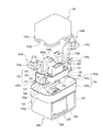
- FIG. 1 is a sectional view showing an example of the entire configuration of an electromagnetic contactor as a switch according to the present invention
- FIG. 2 is an exploded perspective view showing an example of an electromagnetic contactor according to the present invention
- FIG. It is a perspective view which shows a state. 1 to 3, reference numeral 10 denotes an electromagnetic contactor as a switch.
- the electromagnetic contactor 10 includes a contact device 100 in which a contact mechanism is arranged and an electromagnet device 200 that drives the contact device 100. ing.
- the contact device 100 includes an arc extinguishing container 102 that houses the contact mechanism 101.
- the arc extinguishing container 102 has a bowl-shaped metal body 103 that opens a top end of a metal plate material such as aluminum, aluminum alloy, stainless steel or the like formed into a bowl shape by press molding. Yes.
- the arc extinguishing container 102 includes an insulating holding member 105 made of, for example, synthetic resin that holds the pair of fixed contacts 104A and 104B arranged in the bowl-shaped metal body 103.
- the arc-extinguishing container 102 is inserted from the open end surface side of the bowl-shaped metal body 103 and has a lower end surface covering the pair of fixed contacts 104A and 104B and the movable contact 106 arranged so as to be able to contact with and separate from them.
- An open bowl-shaped resin cover 107 is provided.
- the bowl-shaped metal body 103 includes a substantially rectangular bottom plate portion 103a and a rectangular tube portion 103b extending upward from the outer peripheral edge of the bottom plate portion 103a.
- the bottom plate portion 103a is formed with an insertion hole 103c through which a part of a fixed iron core of an electromagnet device 200 described later is inserted at the center.
- the upper part of the insertion hole 103c extends upward through the center of the fixed iron core, and comes into contact with the lower end of the flange part formed on the movable shaft with the movable contact 106 supported by the contact spring at the upper end.
- a positioning piece 111 that regulates the lower end position of the lens is fixed.
- Each of the pair of fixed contacts 104A and 104B is formed symmetrically.
- the pair of fixed contacts 104A and 104B are arranged in the center of the arc extinguishing container 102 and extend downward from the outer end of the contact 104a, with a horizontal contact 104a facing the contact of the movable contact 106.
- a U-shaped bent portion 104b, and a connection terminal portion 104c extending horizontally outward from the other end of the U-shaped bent portion 104b.
- the insulating holding member 105 includes a bottom plate portion 105a disposed in contact with the inner surfaces of the side plate portions 103d and 103e on the short side of the bowl-shaped metal body 103, and the bottom plate portion.
- Contact holding parts 105b and 105c for holding a pair of fixed contacts 104A and 104B formed to face the side plate parts 103d and 103e are provided on the upper surface of 105a.
- each of the contact holding parts 105b and 105c is an inner hook-like shape that extends in the vertical direction and passes through the vertical plate part of the U-shaped bent part 104b of the pair of fixed contacts 104A and 104B and faces each other.
- a portion 121 and an outer flange 122 are provided.
- the inner hook 121 is parallel to the side plates 103d and 103e of the hook metal body 103 while maintaining a predetermined distance, and a central plate 123 extending in an up-and-down direction from the upper edge of the hook metal body 103 is extended to the center plate 123. It is composed of a pair of side plate portions 124 and 125 protruding rightward from the front and rear end portions of the central plate portion 123.
- the outer hook 122 extends in the vertical direction along one of the side plates 103 d and 103 e of the hook metal body 103, and a center plate 126 whose upper end protrudes from the upper end of the hook metal 103 and the center plate 126. It is comprised by a pair of side-plate part 127 and 128 which protrudes to the left from the front-and-back end part.
- the inner flange 121 of the contact holders 105b and 105c is integrally connected by side walls 129 and 130 whose side plates 124 and 125 bulge in the front-rear direction to form a cylindrical part 131. .
- an engagement piece 132 that protrudes outward and engages with the inner surface of the rectangular tube portion 103 b of the bowl-shaped metal body 103 is formed on the lower surface side of the side wall portions 129 and 130.
- an engagement piece 133 that protrudes outward is formed on the side surface of the central plate portion 126 of the outer flange portion 122 of the contact holder holding portions 105b and 105c. This engagement piece 133 is engaged with an engagement recess 134 formed at the upper end on the short side to the rectangular tube portion 103 b of the bowl-shaped metal body 103.
- the pair of fixed contacts 104A and 104B are inserted and held from above by the contact holding portions 105b and 105c.
- the insertion and holding of the fixed contacts 104A and 104B will be described with reference to the fixed contact 104B as shown in FIG.
- the inner vertical plate portion 104b1 in the U-shaped bent portion 104b of the stationary contact 104B is engaged with the center plate portion 123 and the side plate portions 124 and 125 of the inner hook portion 121 of the contact holding portion 105c, Further, the outer vertical plate portion 104b2 in the U-shaped bent portion 104b is inserted from above so as to be engaged with the central plate portion 126 and the side plate portions 127 and 128 of the outer flange portion 122.
- the fixed contact 104A is also inserted and held in the contact holding part 105b in the same manner as described above.
- the resin cover 107 is formed with a peripheral flange portion 107a on the open end surface at the lower end to secure a bonding area with a thick thickness of other portions. Further, the peripheral flange portion 107a has a bottom portion of the U-shaped bent portion 104b of the fixed contacts 104A and 104B at a position facing the fixed contacts 104A and 104B held by the contact holder holding portions 105b and 105c. A notch 107b is formed through which is inserted.
- the movable contact 106 is disposed so that the left and right ends are opposed to the lower side of the contact portion 104a of the fixed contacts 104A and 104B.
- the movable contact 106 is supported by a movable shaft 141 fixed to a movable iron core 212 of an electromagnet device 200 described later.
- the movable shaft 141 has a flange portion 141a protruding outward at the upper end.
- a contact spring 142 that applies a predetermined contact pressure is inserted into the lower end side of the movable contact 106 of the movable shaft 141.
- the movable contact 106 is in a released state, and the contact portions at both ends and the contact portions 104a of the fixed contacts 104A and 104B are separated from each other with a predetermined interval. Further, the movable contact 106 is set so that the contact portions at both ends are in contact with the contact portions 104a of the fixed contacts 104A and 104B with a predetermined contact pressure by the contact spring 142 at the closing position.
- magnet holding portions 151 and 152 are formed on the above-described insulating holding member 105. These magnet holding portions 151 and 152 are in contact with the contact portions 104a of the fixed contacts 104A and 104B and the movable contact 106 inside the contact holding portions 105b and 105c in the left-right direction and holding the fixed contacts 104A and 104B. It faces the contact part from the side surface side in the front-rear direction. In these magnet holders 151 and 152, arc extinguishing permanent magnets 153 and 154 are inserted and held. The magnet holding portions 151 and 152 are disposed inside the side wall portions 129 and 130. It is covered with the resin cover 107 described above.
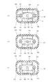
- the arc extinguishing permanent magnets 153 and 154 are magnetized so that their opposing surfaces have the same polarity, for example, N pole, in the thickness direction. Further, the arc extinguishing permanent magnets 153 and 154 are set so that both end portions in the left-right direction are slightly inside the ends of the left and right contact portions of the movable contact 106 as shown in FIG. Yes. Arc extinguishing spaces 155 and 156 are formed on the outer sides of the magnet holding portions 151 and 152 in the left-right direction, respectively.
- the arc extinguishing permanent magnets 153 and 154 can be brought close to the movable contact 106.
- the magnetic flux ⁇ generated from the N pole side of both arc extinguishing permanent magnets 153 and 154 is the contact between the contact 104a of the fixed contacts 104A and 104B and the movable contact 106.
- the portion facing the portion 106a is traversed with a large magnetic flux density from the inside to the outside in the left-right direction.
- connection terminal portion 104c of the fixed contact 104A is connected to the power supply source and the fixed contact 104B is connected to the load side, the direction of the current in the applied state is as shown in FIG.
- the fixed contact 104A flows from the fixed contact 104A through the movable contact 106 to the fixed contact 104B.
- the contact portion 104a of the fixed contacts 104A and 104B and the contact portion 106a of the movable contact 106 are connected. An arc is generated between them.
- the Lorentz force F acting on the arc is increased by the magnetic flux ⁇ from the arc extinguishing permanent magnets 153 and 154, and the arc on the arc extinguishing permanent magnet 153 side is increased. It is greatly stretched toward the arc extinguishing space 155 side.
- the arc extinguishing spaces 155 and 156 are formed wide by the thickness of the arc extinguishing permanent magnets 153 and 154, a long arc length can be taken and the arc can be extinguished reliably.
- the electromagnet device 200 includes a U-shaped magnetic yoke 201 that is flat when viewed from the side, and a cylindrical auxiliary yoke 203 is fixed to the center of the bottom plate portion 202 of the magnetic yoke 201.
- a spool 204 as a plunger driving unit is disposed outside the cylindrical auxiliary yoke 203.
- the spool 204 includes a central cylindrical portion 205 that passes through the cylindrical auxiliary yoke 203, a lower flange portion 206 that protrudes radially outward from the lower end portion of the central cylindrical portion 205, and a little more than the upper end of the central cylindrical portion 205.
- the upper flange portion 207 protrudes radially outward from the lower side.
- An exciting coil 208 is wound around a storage space formed by the central cylindrical portion 205, the lower flange portion 206, and the upper flange portion 207.
- the upper magnetic yoke 210 is fixed between the upper ends of the magnetic yoke 201 serving as the open end.
- the upper magnetic yoke 210 is formed with a through hole 210 a facing the central cylindrical portion 205 of the spool 204 at the central portion.
- a fixed iron core 211 is fixedly disposed on the upper side of the central cylindrical portion 205 of the spool 204, and a movable iron core 212 is disposed below the fixed iron core 211 with a predetermined distance.
- a return spring 213 is inserted between the fixed iron core 211 and the movable iron core 212, and the movable iron core 212 is pressed downward by the return spring 213.
- a movable shaft 141 is fixed to the movable iron core 212. The movable shaft 141 protrudes into the contact device 100 through the central shaft hole of the fixed iron core 211, and the movable contact 106 is held by a contact spring 142 at the upper end thereof.
- the fixed iron core 211 and the movable iron core 212 are covered with a bottomed cylindrical cap 215 whose upper end is opened.
- a flange portion 216 formed by extending in the radial direction at the open end of the cap 215 is sealed and joined to the lower surface of the bowl-shaped metal body 103 by brazing, welding, or the like.
- a sealed container is formed in which the arc extinguishing container 102 and the cap 215 are communicated with each other through the insertion hole 103 c of the bowl-shaped metal body 103.
- a gas such as hydrogen gas, nitrogen gas, a mixed gas of hydrogen and nitrogen, air, or SF 6 is sealed in a sealed container formed by the arc extinguishing container 102 and the cap 215.
- the spool 204 is disposed in the magnetic yoke 201 of the electromagnet device 200. Then, with the movable iron core 212 and the fixed iron core 211 inserted into the cap 215 via the return spring 213, the cap 215 is brazed to the bowl-shaped metal body 103 and fixed by welding or the like. At this time, the fixed iron core 211 is fixed in the insertion hole 103 c of the bowl-shaped metal body 103, and the lower position of the movable shaft 141 is defined by fixing the positioning piece 111 at the center of the bowl-shaped metal body 103.
- the insulating holding member 105 is inserted and held in the bowl-shaped metal body 103.
- the U-shaped bent portions 104b of the pair of fixed contacts 104A and 104B are inserted and held in the contact holding portions 105b and 105c of the insulating holding member 105 so that the contact portions 104a are inside.
- the contact portions 104a of the pair of fixed contacts 104A and 104B face the contact portions 106a of the movable contact 106 from above.
- an adhesive is injected into the U-shaped bent portions 104b of the pair of fixed contacts 104A and 104B, and an adhesive is applied to the lower surface side of the peripheral flange portion 107a of the resin cover 107.
- the resin cover 107 is surrounded by the bottom plate portion 103a of the bowl-shaped metal body 103 from above so that the bottom plate portion of the U-shaped bent portion 104b of the pair of fixed contacts 104A and 104B is inserted into the notch portion 107b.
- the part 107a is brought into contact.
- the peripheral flange portion 107a and the bottom plate portion 103a of the bowl-shaped metal body 103 are bonded by the adhesive, and the bottom plate portion of the U-shaped bent portion 104b of the pair of fixed contacts 104A and 104B and the resin
- the notch 107b of the cover 107 is bonded. Therefore, a sealed arc extinguishing chamber is formed by the bowl-shaped metal body 103, the resin cover 107, and the cap 215.
- a gas such as hydrogen gas, nitrogen gas, a mixed gas of hydrogen and nitrogen, air, SF 6 or the like is injected from a gas injection hole (not shown) formed in the resin cover 107. Seal the injection hole.
- the electromagnetic contactor 10 can be comprised.
- a power supply source that supplies a large current is connected to the connection terminal portion 104c of the fixed contact 104A, and a load is applied to the connection terminal portion 104c of the fixed contact 104B.
- the exciting coil 208 in the electromagnet device 200 is in a non-excited state and the electromagnet device 200 is in a released state in which the exciting force that raises the movable iron core 212 is not generated.
- the movable iron core 212 is urged by the return spring 213 in a direction away from the fixed iron core 211.
- the contact portion 106a of the movable contact 106 of the contact mechanism 101 connected to the movable iron core 212 via the movable shaft 141 is spaced downward from the contact portion 104a of the fixed contacts 104A and 104B by a predetermined distance. .
- the current path between the stationary contacts 104A and 104B is in an interrupted state, and the contact mechanism 101 is in an open state.
- the urging force of the return spring 213 acts on the movable iron core 212, so that the movable iron core 212 does not inadvertently drop due to external vibrations or shocks, so that malfunction can be assured. Can be prevented.
- the movable iron core 212 rises quickly against the urging force of the return spring 213.
- the rising of the movable iron core 212 is stopped when the upper end of the movable iron core 212 contacts the lower end of the fixed iron core 211.
- the movable contact 106 connected to the movable iron core 212 via the movable shaft 141 is also raised, and the contact portion 106a thereof is the contact portion 104a of the fixed contacts 104A and 104B.
- the fixed contacts 104A and 104B have an L-shaped portion formed by the contact portion 104a and the U-shaped bent portion 104b, so that the upper plate portion 116 and the lower plate portion 118 are formed. In other words, a current in the reverse direction flows between the movable contact 106 and the movable contact 106 facing the same.
- the magnetic flux generated by the current flowing through the vertical plate portion of the L-shaped portion of the stationary contacts 104A and 104B can be applied to the contact portion between the stationary contacts 104A and 104B and the movable contact 106.
- the Lorentz force which resists an electromagnetic repulsive force can be generated by increasing the magnetic flux density at the contact portion between the fixed contacts 104A and 104B and the movable contact 106.
- the arc generation portion of the contact portion 104a of the fixed contact 104B and the contact portion 106a of the movable contact 106 crosses from the inside to the outside in the longitudinal direction of the movable contact 106 and reaches the S pole to form a magnetic field. Accordingly, the magnetic fluxes of the arc extinguishing permanent magnets 153 and 154 are both between the contact part 104a of the fixed contact 104A and the contact part 106a of the movable contact 106, and between the contact part 104a of the fixed contact 104B and the contact of the movable contact 1060. The portions 1060a cross in the opposite directions in the longitudinal direction of the movable contact 106.
- the arc generated between the contact portion 104a of the fixed contact 104A and the contact portion 106a of the movable contact 106 due to the Lorentz force F passes through the arc extinguishing space 155 from the side surface of the contact portion 104a of the fixed contact 104A. It is greatly stretched so as to reach the upper surface side of the movable contact 106 and is extinguished. Further, in the arc extinguishing space 155, the magnetic flux is below and above the lower side and the upper side with respect to the direction of the magnetic flux between the contact portion 104 a of the fixed contact 104 ⁇ / b> A and the contact portion 106 a of the movable contact 106. Will tilt.
- the arc stretched in the arc extinguishing space 155 by the tilted magnetic flux is further stretched in the direction of the corner of the arc extinguishing space 155, the arc length can be increased, and good interruption performance can be obtained. .
- the current I flows from the movable contact 106 side to the fixed contact 104B side, and the magnetic flux ⁇ . Is the right direction from the inside to the outside.
- the arc extinguishing space 155 is directed to the arc extinguishing space 155 side perpendicular to the longitudinal direction of the movable contact 106 and perpendicular to the opening / closing direction of the contact portion 104a of the fixed contact 104B and the movable contact 106.
- a large Lorentz force F acts.
- the arc generated between the contact portion 104a of the fixed contact 104B and the movable contact 106 due to the Lorentz force F passes through the arc extinguishing space 155 from the upper surface side of the movable contact 106 to the fixed contact 104B. It is greatly stretched to reach the side and extinguished. Further, in the arc extinguishing space 155, as described above, on the lower side and the upper side, the lower side and the upper side with respect to the direction of the magnetic flux between the contact part 104a of the stationary contact 104B and the contact part 106a of the movable contact 106 and The magnetic flux is inclined upward.
- the arc stretched in the arc extinguishing space 155 by the tilted magnetic flux is further stretched in the direction of the corner of the arc extinguishing space 155, the arc length can be increased, and good interruption performance can be obtained.
- the electromagnetic contactor 10 is turned on and the regenerative current is flowing from the load side to the DC power source side and the release state is set, the direction of the current in FIG. 4B is reversed. Therefore, the same arc extinguishing function is exhibited except that the Lorentz force F acts on the arc extinguishing space 156 side and the arc is extended to the arc extinguishing space 156 side.
- the arc extinguishing permanent magnets 153 and 154 are disposed in the magnet holding portions 151 and 152 formed in the insulating holding member 105, the arc directly contacts the arc extinguishing permanent magnets 153 and 154. There is nothing. For this reason, the magnetic characteristics of the arc extinguishing permanent magnets 153 and 154 can be stably maintained, and the interruption performance can be stabilized.
- the bowl-shaped metal body 103 and the resin cover 107 are fixed by an adhesive, and similarly, the resin cover 107 and the U-shaped bent portions 104b of the pair of fixed contacts 104A and 104B are also fixed by an adhesive. For this reason, the bowl-shaped metal body 103 and the resin cover 107 can be fixed without performing brazing, welding, or the like. Therefore, since it is not necessary to apply heat to the fixing of the bowl-shaped metal body 103 and the resin cover 107, good sealing can be performed without causing thermal deformation or thermal stress.
- the insulation holding member 105b and the resin cover 107 can cover and insulate the inner peripheral surface of the bowl-shaped metal body 103, there is no short circuit of the arc when the current is interrupted, and the current can be reliably interrupted. Further, the insulating holding member 105 and the resin cover 107 can perform the insulating function, the positioning function of the arc extinguishing permanent magnets 153 and 154, and the arc extinguishing permanent magnets 153 and 154 from the arc. Cost can be reduced.
- the arc extinguishing container 102 includes the pair of fixed contacts disposed on the upper surface side of the bowl-shaped metal body 103 and the bottom plate portion 103a of the bowl-shaped metal body 103.
- the insulating holding member 105 that holds 104A and 104B, the pair of fixed contacts 104A and 104B, the movable contact 106, and the resin cover 107 that covers the arc extinguishing permanent magnets 153 and 154 are configured.
- the cage metal body 103 and the resin cover 107 are fixed with an adhesive, and the resin cover 107 and the pair of fixed contacts 104A and 104B are bonded and held with an adhesive.
- the bowl-shaped metal body 103 and the resin cover 107 can be bonded in an airtight state with an adhesive. Therefore, it is not necessary to apply expensive ceramics as the arc extinguishing container, and the manufacturing cost of the arc extinguishing container 102 can be greatly reduced. In addition, in order to maintain airtightness, it is not necessary to perform brazing, welding, or the like, and it is only necessary to fix with an adhesive, so that thermal deformation and generation of thermal stress can be reliably prevented.
- the contact portion 104a, the U-shaped bent portion 104b, and the connection terminal portion 104c are integrally formed with the pair of fixed contacts 104A and 104B, the fixed contacts 104A and 104B are manufactured at low cost. Can be manufactured easily.
- the arc extinguishing permanent magnets 153 and 154 are arranged inside the resin cover 107, the magnetic flux density across the arc can be increased, and the arc extinguishing spaces 155 and 156 are used for arc extinguishing.
- the permanent magnets 153 and 154 can be formed wider than the thickness of the permanent magnets 153, can take a long arc length, and can reliably extinguish the arc.
- the movable contact 106 of the contact device 100 can be moved by the electromagnet device 200, and an electromagnetic contactor can be easily configured.
- the case where the fixed contacts 104A and 104B constituting the contact mechanism 101 are formed in an L shape in the vicinity of the movable contact 106 will be described.
- the present invention is configured according to the above embodiment.
- the movable contact 106 can be formed in a C shape so as to be sandwiched between the upper and lower sides, and a contact mechanism having any other configuration can be applied.
- the sealed container was comprised with the arc-extinguishing container 102 and the cap 215 and gas was enclosed in this sealed container, it was not limited to this,
- block is not limited to this. If it is low, gas filling may be omitted.
- the arc extinguishing permanent magnets 153 and 154 are arranged on the inner peripheral surface of the resin cover 107 has been described.
- the present invention is not limited to the above configuration, and arc extinguishing permanent magnets may be disposed on the outer peripheral surface of the resin cover 107, and further, arc extinguishing permanent magnets 153 and 154 are omitted. You may do it.
- the case where the electromagnet device 200 has the U-shaped magnetic yoke 201 has been described.
- a bottomed cylindrical magnetic yoke may be applied. Any configuration can be applied as long as the fixed contacts 104A and 104B can be moved toward and away from the fixed contacts 104A and 104B.
- the present invention is applied to an electromagnetic contactor.
- the present invention is not limited to this, and the present invention is applied to a switch having an arc extinguishing container such as an electromagnetic relay or a switch. can do.
- the arc-extinguishing container that seals the contact mechanism in a state of surrounding the contact mechanism does not require heating such as projection welding, laser welding, brazing, or the like, and is simply performed with an adhesive without using a joining process. It is possible to provide a switch such as an electromagnetic contactor that can be easily formed by simply bonding the resin cover to the resin cover.
- Electromagnetic contactor 11 ... Exterior insulation container, 100 ... Contact apparatus, 101 ... Contact mechanism, 102 ... Arc-extinguishing container, 103 ... Saddle-shaped metal body, 104A, 104B ... Fixed contact, 104a ... Contact part, 104b ... U-shaped bent part, 104c ... connection terminal part, 105 ... insulating holding member, 105b, 105c ... contact holding part, 106 ... movable contact, 106a ... contact part, 107 ... resin cover, 107a ... peripheral flange part, 107b ... Notch part, 141 ... Movable shaft, 142 ...
- Electromagnet device 201 ... Magnetic yoke 203 ... Cylindric auxiliary yoke 204 ... Spool 208 ... Excitation coil 210 ... Upper magnetic yoke 211 ... Fixed iron core 212 ... Movable iron core 21 ... return spring, 215 ... cap
Abstract
密封容器を容易に形成することができる開閉器を提供する。消弧容器(102)に、所定間隔を保って配置された一対の固定接触子(104A),(104B)及び当該一対の固定接触子に対して接離可能に配設された可動接触子(106)を内装した開閉器であって、前記消弧容器(102)は、上面を開放した桶状金属体(103)と、該桶状金属体の内面側に配置された前記一対の固定接触子を前記可動接触子と対向させて保持する絶縁保持部材(105)と、前記桶状金属体の開放端面側から前記一対の固定接触子及び可動接触子を覆う下端を開放した桶状の樹脂カバー(107)とで構成され、前記樹脂カバー(107)の開放端の周囲を前記桶状金属体(103)の底面に接着剤で封止している。
Description
本発明は、消弧容器に固定接触子及びこれに接離可能に配置された可動接触子を内装した開閉器に関する。
この種の開閉器としては、例えば特許文献1に記載された電磁接触、スイッチ、タイマー等の開閉装置に使用される端子のシール構造が知られている。このシール構造は、接点機構を収納可能な封止ケースとこの封止ケースの上部を閉塞する封止カバーとで金属製の封止ケースブロックを構成している。そして、封止カバーに接点機構ブロックの接続端子を挿通する一対の挿通孔を形成し、これら一対の挿通孔内に接続端子を挿通した状態で、シール材を注入、固化してシールする端子のシール構造としている。また、前記シール材の熱膨張係数を液状熱硬化性ポリマーに無機質充填材を添加して前記封止ケースブロックの線膨張係数と同等以上としている。
ところで、上記特許文献1に記載された従来例にあっては、筒状の封止ケースブロック内に絶縁ケースを配置するとともに、封止ケースブロックの上端に封止カバーを配置し、この封止カバー内に端子孔を形成し、この端子孔内に端子を配置した状態で、端子孔と端子間にシール材を注入して固化し、消弧容器を形成するようにしている。
このように、封止カバーに端子孔を形成し、この端子孔に端子を配置してからシール材を端子孔及び端子間にシール材を注入して固化する場合には、シール材を注入箇所に完全に行き渡らせるために比較的大きな注入圧力を必要とする。このため、シール材を注入する部位をシール材の漏れがないように精密に形成する必要があり、成形コストが嵩むという未解決の課題がある。
そこで、本発明は、上記従来例の未解決の課題に着目してなされたものであり、接点機構を囲んだ状態で封止する消弧容器を容易に形成することができる開閉器を提供することを目的としている。
そこで、本発明は、上記従来例の未解決の課題に着目してなされたものであり、接点機構を囲んだ状態で封止する消弧容器を容易に形成することができる開閉器を提供することを目的としている。
上記目的を達成するために、本発明に係る開閉器の第1の態様は、消弧容器に、所定間隔を保って配置された一対の固定接触子及び当該一対の固定接触子に対して接離可能に配設された可動接触子を内装した開閉器である。そして、前記消弧容器は、上面を開放した桶状金属体と、該桶状金属体の内面側に配置された前記一対の固定接触子を前記可動接触子と対向させて保持する絶縁保持部材と、前記桶状金属体の開放端面側から前記一対の固定接触子及び可動接触子を覆う下端を開放した桶状の樹脂カバーとで構成されている。さらに、前記樹脂カバーの開放端の周囲を前記桶状金属体の底面に接着剤で封止している。
この構成によると、気密性の高い消弧容器を形成する際に、プロジェクション溶接やレーザ溶接等の溶接を行うことなく、桶状金属体の内面側に一対の固定接触子を保持する絶縁保持部材を配置し、この絶縁保持部材で保持された一対の固定端子を囲むように桶状の樹脂カバーを配置し、この樹脂カバーの開放端の周囲を接着剤で固定することにより、シールを施すことができる。このため、溶接やろう付け等の熱を加える接合を行うことがなく、容易に、且つ確実に気密性の高い消弧容器を形成することができる。
しかも、桶状金属体と樹脂カバーとを接着剤で接着するので、シール剤の注入のように圧力を掛けて注入する必要がなく、樹脂カバーと金属桶状体とを容易に接着することができる。
しかも、桶状金属体と樹脂カバーとを接着剤で接着するので、シール剤の注入のように圧力を掛けて注入する必要がなく、樹脂カバーと金属桶状体とを容易に接着することができる。
また、本発明に係る開閉器の第2の態様は、前記一対の固定接触子が、前記可動接触子と対向する接点部と、外部接続端子部との間にU字状折曲部が形成され、前記絶縁保持部材が、前記一対の固定子のU字状折曲部を挿通保持する接点保持部が形成され、前記樹脂カバーが、その側面を前記一対の固定接触子のU字状折曲部内に挿通し、接着剤で固定されている。
この第2の態様によると、一対の固定接触子を可動接触子と対向する接点部と外部接続端子部との間にU字状折曲部が形成され、このU字状折曲部を接点保持部で保持し、U字状折曲部内に樹脂カバーの側面を挿通して接着剤で固定するので、一対の固定接触子の固定を容易に行うことができる。
この第2の態様によると、一対の固定接触子を可動接触子と対向する接点部と外部接続端子部との間にU字状折曲部が形成され、このU字状折曲部を接点保持部で保持し、U字状折曲部内に樹脂カバーの側面を挿通して接着剤で固定するので、一対の固定接触子の固定を容易に行うことができる。
また、本発明に係る開閉器の第3の態様は、前記絶縁保持部材が、前記一対の固定接触子の接点部及び前記可動接触子の接点部に対向してアーク消弧用永久磁石を保持する磁石保持部が形成されている。
この第3の形態によると、絶縁保持部材にアーク消弧用永久磁石を配置するので、アークを所定方向に長く引き延ばすことができ、アークの消弧を容易に、且つ確実に行うことができる。
この第3の形態によると、絶縁保持部材にアーク消弧用永久磁石を配置するので、アークを所定方向に長く引き延ばすことができ、アークの消弧を容易に、且つ確実に行うことができる。
また、本発明に係る開閉器の第4の態様は、前記桶状金属体の下面側に前記可動接触子を前記一対の固定接触子に対して接離可能に可動させる電磁石装置が配置されている。
この第4の態様によると、桶状金属体の下面側に電磁石装置を配置し、この電磁石装置で可動接触子を固定接触子に対して接離可能に可動させることができ、電磁開閉器としての電磁接触器を構成することができる。
この第4の態様によると、桶状金属体の下面側に電磁石装置を配置し、この電磁石装置で可動接触子を固定接触子に対して接離可能に可動させることができ、電磁開閉器としての電磁接触器を構成することができる。
本発明によれば、桶状金属体内に一対の固定接触子を可動接触子に対向させて保持する絶縁保持部材を配置し、桶状金属体の開放端側から一対の固定接触子及び可動接触子を桶状の樹脂カバーで覆い、この樹脂カバーの開放端の周囲を桶状金属体の底面に接着剤で封止している。このため、プロジェクション溶接やレーザ溶接、ろう付け等の加熱を必要と接合処理を行うことなく、単に接着剤で桶状金属体と樹脂カバーとを接着するだけで、気密性の高い消弧容器を容易に形成することができる。
以下、本発明の実施の形態を図面に基づいて説明する。
図1は本発明に係る開閉器としての電磁接触器の全体構成の一例を示す断面図、図2は本発明に係る電磁接触器の一例を示す分解斜視図、図3は固定接触子の装着状態を示す斜視図である。
これら図1~図3において、10は開閉器としての電磁接触器であり、この電磁接触器10は接点機構を配置した接点装置100と、この接点装置100を駆動する電磁石装置200とで構成されている。
図1は本発明に係る開閉器としての電磁接触器の全体構成の一例を示す断面図、図2は本発明に係る電磁接触器の一例を示す分解斜視図、図3は固定接触子の装着状態を示す斜視図である。
これら図1~図3において、10は開閉器としての電磁接触器であり、この電磁接触器10は接点機構を配置した接点装置100と、この接点装置100を駆動する電磁石装置200とで構成されている。
接点装置100は、図1~図3から明らかなように、接点機構101を収納する消弧容器102を有する。この消弧容器102は、図1~図3に示すように、アルミニウム、アルミニウム合金、ステンレス鋼等の金属板材をプレス成形によって桶状に成形した上端を開放する桶状金属体103を有している。
また、消弧容器102は、桶状金属体103内に配置された一対の固定接触子104A及び104Bを保持する例えば合成樹脂製の絶縁保持部材105を有している。さらに、消弧容器102は桶状金属体103の開放端面側から挿入されて一対の固定接触子104A及び104Bとこれらに対して接離可能に配設された可動接触子106を覆う下端面を開放した桶状の樹脂カバー107を有している。
また、消弧容器102は、桶状金属体103内に配置された一対の固定接触子104A及び104Bを保持する例えば合成樹脂製の絶縁保持部材105を有している。さらに、消弧容器102は桶状金属体103の開放端面側から挿入されて一対の固定接触子104A及び104Bとこれらに対して接離可能に配設された可動接触子106を覆う下端面を開放した桶状の樹脂カバー107を有している。
桶状金属体103は、略長方形の底板部103aと、この底板部103aの外周縁から上方に延長する角筒部103bとを備えている。底板部103aには、中央部に後述する電磁石装置200の固定鉄心の一部を挿通する挿通孔103cが形成されている。この挿通孔103cの上部側には、固定鉄心の中心部を通って上方に延長し、上端に可動接触子106を接触バネで支持した可動軸に形成したフランジ部の下端と接触して可動軸の下端位置を規制する位置決め片111が固定されている。
一対の固定接触子104A及び104Bのそれぞれは、左右対称形に形成されている。これら一対の固定接触子104A及び104Bは、消弧容器102の中央部に配置されて可動接触子106の接点部と対向する水平な接点部104aと、この接点部104aの外側端から下方に延長するU字状折曲部104bと、このU字状折曲部104bの他端側から外方に水平に延長する接続端子部104cとを備えている。
絶縁保持部材105は、図2及び図3で特に明らかなように、桶状金属体103の短辺側の側板部103d及び103eの内面に接触して配置される底板部105aと、この底板部105aの上面に側板部103d及び103eに対向して形成された一対の固定接触子104A及び104Bを保持する接触子保持部105b及び105cとを備えている。
ここで、接触子保持部105b及び105cのそれぞれは、一対の固定接触子104A及び104BのU字状折曲部104bの垂直板部を挿通保持する上下方向に延長して互いに対向する内側樋状部121及び外側樋状部122を備えている。
ここで、接触子保持部105b及び105cのそれぞれは、一対の固定接触子104A及び104BのU字状折曲部104bの垂直板部を挿通保持する上下方向に延長して互いに対向する内側樋状部121及び外側樋状部122を備えている。
内側樋状部121は、桶状金属体103の側板部103d及び103eと所定距離を保って平行で上下方向に上端が桶状金属体103の上端より突出して延長する中央板部123と、この中央板部123の前後端部から右方向に突出する一対の側板部124及び125とで構成されている。
外側樋状部122は桶状金属体103の側板部103d及び103eの一方に沿って上下方向延長し、上端が桶状金属体103の上端より突出する中央板部126と、この中央板部126の前後端部から左方に突出する一対の側板部127及び128とで構成されている。
外側樋状部122は桶状金属体103の側板部103d及び103eの一方に沿って上下方向延長し、上端が桶状金属体103の上端より突出する中央板部126と、この中央板部126の前後端部から左方に突出する一対の側板部127及び128とで構成されている。
なお、接触子保持部105b及び105cの内側樋状部121は、その側板部124及び125が前後方向に膨出する側壁部129及び130で一体に連結されて筒状部131が形成されている。また、側壁部129及び130の下面側に外方に突出して桶状金属体103の角筒部103bの内面に係合する係合片132が形成されている。
さらに、接触子保持部105b及び105cの外側樋状部122の中央板部126の該側面に外方に突出する係合片133が形成されている。この係合片133が桶状金属体103の角筒部103bへの短辺側の上端に形成された係合凹部134に係合される。
さらに、接触子保持部105b及び105cの外側樋状部122の中央板部126の該側面に外方に突出する係合片133が形成されている。この係合片133が桶状金属体103の角筒部103bへの短辺側の上端に形成された係合凹部134に係合される。
そして、一対の固定接触子104A及び104Bが、図3に示すように、接触子保持部105b及び105cに上方から挿通して保持される。この固定接触子104A及び104Bの挿通保持は、固定接触子104Bについて説明すると、図3に示すように、保持される。すなわち、固定接触子104BのU字状折曲部104bにおける内側垂直板部104b1を接触子保持部105cの内側樋状部121の中央板部123、側板部124及び125の内側に係合させ、且つU字状折曲部104bにおける外側垂直板部104b2を外側樋状部122の中央板部126、側板部127及び128に係合させるように上方から挿通する。
固定接触子104Aについても上記と同様にして接触子保持部105bに挿通保持させる。
樹脂カバー107は、下端の開放端面に、他の部の厚みが厚い肉厚で接着面積を確保する周鍔部107aが形成されている。また、周鍔部107aには、接触子保持部105b及び105cに保持されている固定接触子104A及び104Bに対向する位置に、これら固定接触子104A及び104BのU字状折曲部104bの底部を挿通する切欠部107bが形成されている。
樹脂カバー107は、下端の開放端面に、他の部の厚みが厚い肉厚で接着面積を確保する周鍔部107aが形成されている。また、周鍔部107aには、接触子保持部105b及び105cに保持されている固定接触子104A及び104Bに対向する位置に、これら固定接触子104A及び104BのU字状折曲部104bの底部を挿通する切欠部107bが形成されている。
そして、可動接触子106は、左右両端部を固定接触子104A及び104Bの接点部104aの下側に対向するように配設されている。この可動接触子106は後述する電磁石装置200の可動鉄心212に固定された可動軸141に支持されている。
可動軸141は、上端に外方に突出するフランジ部141aが形成されている。この可動軸141の可動接触子106の下端側に所定の接触圧を与える接触スプリング142が挿通されている。
可動軸141は、上端に外方に突出するフランジ部141aが形成されている。この可動軸141の可動接触子106の下端側に所定の接触圧を与える接触スプリング142が挿通されている。
この可動接触子106は、釈放状態で、両端の接点部と固定接触子104A及び104Bの接点部104aとが所定間隔を保って離間した状態となる。また、可動接触子106は、投入位置で、両端の接点部が固定接触子104A及び104Bの接点部104aに、接触スプリング142による所定の接触圧で接触するように設定されている。
また、前述した絶縁保持部材105には、磁石保持部151及び152が形成されている。これら磁石保持部151及び152は、接触子保持部105b及び105cの左右方向内側で且つ固定接触子104A及び104Bを保持した状態で、これら固定接触子104A及び104Bの接点部104aと可動接触子106の接点部とに対して前後方向の側面側から対向している。これら磁石保持部151及び152内にはアーク消弧用永久磁石153及び154が挿通保持されている。磁石保持部151及び152は、側壁部129及び130の内側に配置されている。前述した樹脂カバー107によって覆われる。
アーク消弧用永久磁石153及び154は、厚み方向に互いの対向面が同極例えばN極となるように着磁されている。また、アーク消弧用永久磁石153及び154は、左右方向の両端部がそれぞれ、図4に示すように、可動接触子106における左右の接点部の端部より僅かに内側となるよう設定されている。そして、磁石保持部151及び152の左右方向の外側にそれぞれアーク消弧空間155及び156が形成されている。
このように、アーク消弧用永久磁石153及び154を樹脂カバー107の内周面側に配置することにより、アーク消弧用永久磁石153及び154を可動接触子106に近接させることができる。このため、両アーク消弧用永久磁石153及び154のN極側から出る磁束φが、図4(a)に示すように、固定接触子104A及び104Bの接点部104aと可動接触子106の接点部106aとの対向部を左右方向に内側から外側に大きな磁束密度で横切ることになる。
したがって、固定接触子104Aの接続端子部104cを電力供給源に接続し、固定接触子104Bを負荷側に接続するものとすると、投入状態の電流の方向は、図4(b)に示すように、固定接触子104Aから可動接触子106を通じて固定接触子104Bに流れることになる。そして、投入状態から可動接触子106を固定接触子104A及び104Bから上方に離間させて釈放状態とする場合に、固定接触子104A及び104Bの接点部104aと可動接触子106の接点部106aとの間にアークが発生する。
このアークは、図4(c)に示すように、アーク消弧用永久磁石153及び154からの磁束φにより、アークに作用するローレンツ力Fが大きくなり、アーク消弧用永久磁石153側のアーク消弧空間155側に大きく引き伸ばされる。このとき、アーク消弧空間155及び156はアーク消弧用永久磁石153及び154の厚み分広く形成されているので、長いアーク長をとることができ、アークを確実に消弧することができる。
因みに、アーク消弧用永久磁石153及び154を、図5(a)~(c)に示すように、樹脂カバー107の外側に配置する場合には、固定接触子104A及び104Bの接点部104aと可動接触子106の接点部106aとの対向位置までの距離が長くなり、本実施形態と同一の永久磁石を適用した場合に、アークを横切る磁束密度が少なくなる。
このため、投入状態から釈放状態に移行する際に発生するアークに作用するローレンツ力が小さくなり、アークを十分に引き伸ばすことができなくなる。アークの消弧性能を向上させるために、アーク消弧用永久磁石153及び154の着磁量を増加させる必要がある。
このため、投入状態から釈放状態に移行する際に発生するアークに作用するローレンツ力が小さくなり、アークを十分に引き伸ばすことができなくなる。アークの消弧性能を向上させるために、アーク消弧用永久磁石153及び154の着磁量を増加させる必要がある。
しかも、アーク消弧用永久磁石153及び154を固定接触子104A及び104Bと可動接触子106の接点部との距離を短くするためには樹脂カバー107の前後方向の奥行きを狭くする必要があり、アークを消弧するための十分なアーク消弧空間を確保することができないという問題点がある。
しかしながら、上記実施形態によると、アーク消弧用永久磁石153及び154を樹脂カバー107の内側に配置するので、上述した樹脂カバー107の外側にアーク消弧用永久磁石153及び154を配置する場合の問題点を解決することができる。
しかしながら、上記実施形態によると、アーク消弧用永久磁石153及び154を樹脂カバー107の内側に配置するので、上述した樹脂カバー107の外側にアーク消弧用永久磁石153及び154を配置する場合の問題点を解決することができる。
電磁石装置200は、図1に示すように、側面から見て扁平なU字形状の磁気ヨーク201を有し、この磁気ヨーク201の底板部202の中央部に円筒状補助ヨーク203が固定されている。この円筒状補助ヨーク203の外側にプランジャ駆動部としてのスプール204が配置されている。
このスプール204は、円筒状補助ヨーク203を挿通する中央円筒部205と、この中央円筒部205の下端部から半径方向外方に突出する下フランジ部206と、中央円筒部205の上端より僅かに下側から半径方向外方に突出する上フランジ部207とで構成されている。そして、中央円筒部205、下フランジ部206及び上フランジ部207で構成される収納空間に励磁コイル208が巻装されている。
このスプール204は、円筒状補助ヨーク203を挿通する中央円筒部205と、この中央円筒部205の下端部から半径方向外方に突出する下フランジ部206と、中央円筒部205の上端より僅かに下側から半径方向外方に突出する上フランジ部207とで構成されている。そして、中央円筒部205、下フランジ部206及び上フランジ部207で構成される収納空間に励磁コイル208が巻装されている。
そして、磁気ヨーク201の開放端となる上端間に上部磁気ヨーク210が固定されている。この上部磁気ヨーク210は、中央部にスプール204の中央円筒部205に対向する貫通孔210aが形成されている。
そして、スプール204の中央円筒部205内の上方側に、固定鉄心211が固定配置され、この固定鉄心211の下側に所定距離保って可動鉄心212が配置されている。固定鉄心211及び可動鉄心212間には復帰スプリング213が介挿され、この復帰スプリング213によって、可動鉄心212が下方に押圧されている。また、可動鉄心212には可動軸141が固定されている。この可動軸141が固定鉄心211の中心軸孔を通って接点装置100内に突出され、その上端に可動接触子106が接触スプリング142によって保持されている。
そして、スプール204の中央円筒部205内の上方側に、固定鉄心211が固定配置され、この固定鉄心211の下側に所定距離保って可動鉄心212が配置されている。固定鉄心211及び可動鉄心212間には復帰スプリング213が介挿され、この復帰スプリング213によって、可動鉄心212が下方に押圧されている。また、可動鉄心212には可動軸141が固定されている。この可動軸141が固定鉄心211の中心軸孔を通って接点装置100内に突出され、その上端に可動接触子106が接触スプリング142によって保持されている。
そして、固定鉄心211及び可動鉄心212が上端を開放した有底円筒状のキャップ215で覆われている。このキャップ215の開放端に半径方向に延長して形成したフランジ部216が桶状金属体103の下面にろう付け、溶接等によってシール接合されている。これによって、消弧容器102及びキャップ215が桶状金属体103の挿通孔103cを介して連通される密封容器が形成されている。
そして、消弧容器102及びキャップ215で形成される密封容器内に水素ガス、窒素ガス、水素及び窒素の混合ガス、空気、SF6等のガスが封入されている。
そして、消弧容器102及びキャップ215で形成される密封容器内に水素ガス、窒素ガス、水素及び窒素の混合ガス、空気、SF6等のガスが封入されている。
次に、上記実施形態の動作を説明する。
先ず、電磁接触器10を構成するには、電磁石装置200の磁気ヨーク201内にスプール204を配置する。そして、可動鉄心212及び固定鉄心211をキャップ215内に復帰スプリング213を介して挿入した状態で、キャップ215を桶状金属体103にろう付け、溶接等によって固定する。このとき、固定鉄心211は桶状金属体103の挿通孔103c内に固定され、可動軸141の下方側位置が桶状金属体103の中央部に位置決め片111を固定することによって規定される。
先ず、電磁接触器10を構成するには、電磁石装置200の磁気ヨーク201内にスプール204を配置する。そして、可動鉄心212及び固定鉄心211をキャップ215内に復帰スプリング213を介して挿入した状態で、キャップ215を桶状金属体103にろう付け、溶接等によって固定する。このとき、固定鉄心211は桶状金属体103の挿通孔103c内に固定され、可動軸141の下方側位置が桶状金属体103の中央部に位置決め片111を固定することによって規定される。
一方、接点装置100については、桶状金属体103内に、絶縁保持部材105を挿通保持する。この絶縁保持部材105の接触子保持部105b及び105cには一対の固定接触子104A及び104BのU字状折曲部104bを接点部104aが内側となるように挿入保持させる。この状態で、一対の固定接触子104A及び104Bの接点部104aが可動接触子106の接点部106aに上方から対向することになる。
そして、一対の固定接触子104A及び104BのU字状折曲部104bに図1に示すように接着剤を注入するとともに、樹脂カバー107の周鍔部107aの下面側に接着剤を塗布する。この状態で、樹脂カバー107を切欠部107bに一対の固定接触子104A及び104BのU字状折曲部104bの底板部を挿通させるように上方から桶状金属体103の底板部103aに周鍔部107aを当接させる。
これにより、接着剤によって、周鍔部107aと桶状金属体103の底板部103aとが接着されるとともに、一対の固定接触子104A及び104BのU字状折曲部104bの底板部と、樹脂カバー107の切欠部107bとが接着される。このため、桶状金属体103、樹脂カバー107及びキャップ215とで、密封された消弧室が形成される。
その後、接着剤が固化した状態で、樹脂カバー107に形成した図示しないガス注入孔から水素ガス、窒素ガス、水素及び窒素の混合ガス、空気、SF6等のガスを注入し、ガス注入後にガス注入孔を封止する。これにより、電磁接触器10を構成することができる。
その後、接着剤が固化した状態で、樹脂カバー107に形成した図示しないガス注入孔から水素ガス、窒素ガス、水素及び窒素の混合ガス、空気、SF6等のガスを注入し、ガス注入後にガス注入孔を封止する。これにより、電磁接触器10を構成することができる。
このようにして構成された電磁接触器10に対して、固定接触子104Aの接続端子部104cに例えば大電流を供給する電力供給源を接続し、固定接触子104Bの接続端子部104cに負荷を接続する。
この状態で、電磁石装置200における励磁コイル208が非励磁状態にあって、電磁石装置200で可動鉄心212を上昇させる励磁力を発生していない釈放状態にあるものとする。この釈放状態では、可動鉄心212が復帰スプリング213によって、固定鉄心211から下方に離れる方向に付勢される。
この状態で、電磁石装置200における励磁コイル208が非励磁状態にあって、電磁石装置200で可動鉄心212を上昇させる励磁力を発生していない釈放状態にあるものとする。この釈放状態では、可動鉄心212が復帰スプリング213によって、固定鉄心211から下方に離れる方向に付勢される。
このため、可動鉄心212に可動軸141を介して連結されている接点機構101の可動接触子106の接点部106aが固定接触子104A及び104Bの接点部104aから下方に所定距離だけ離間している。このため、固定接触子104A及び104B間の電流路が遮断状態にあり、接点機構101が開極状態となっている。
このように、釈放状態では、可動鉄心212に復帰スプリング213による付勢力が作用しているので、可動鉄心212が外部からの振動や衝撃等によって不用意に下降することがなく、誤動作を確実に防止することができる。
このように、釈放状態では、可動鉄心212に復帰スプリング213による付勢力が作用しているので、可動鉄心212が外部からの振動や衝撃等によって不用意に下降することがなく、誤動作を確実に防止することができる。
この釈放状態から、電磁石装置200の励磁コイル208を励磁すると、この電磁石装置200で励磁力を発生させて、可動鉄心212を復帰スプリング213の付勢力に抗して上方に押し下げる。
このとき、可動鉄心212及び磁気ヨーク201の底板部202間には、円筒状補助ヨーク203を通じて磁路が形成される。このため、可動鉄心212の上面と固定鉄心211の下面との間の磁束密度が大きくなり、可動鉄心212を吸引する大きな吸引力が作用する。
このとき、可動鉄心212及び磁気ヨーク201の底板部202間には、円筒状補助ヨーク203を通じて磁路が形成される。このため、可動鉄心212の上面と固定鉄心211の下面との間の磁束密度が大きくなり、可動鉄心212を吸引する大きな吸引力が作用する。
したがって、可動鉄心212が復帰スプリング213の付勢力に抗して速やかに上昇する。そして、可動鉄心212の上昇は、可動鉄心212の上端が、固定鉄心211の下端に当接することにより停止される。
このように、可動鉄心212が上昇することにより、可動鉄心212に可動軸141を介して連結されている可動接触子106も上昇し、その接点部106aが固定接触子104A及び104Bの接点部104aに接触スプリング142の接触圧で接触する。
このように、可動鉄心212が上昇することにより、可動鉄心212に可動軸141を介して連結されている可動接触子106も上昇し、その接点部106aが固定接触子104A及び104Bの接点部104aに接触スプリング142の接触圧で接触する。
このため、外部電力供給源の大電流が固定接触子104A、可動接触子106、及び固定接触子104Bを通じて負荷に供給される閉極状態となる。
このとき、固定接触子104A及び104Bと可動接触子106との間に可動接触子106を開極させる方向の電磁反発力が発生する。
しかしながら、固定接触子104A及び104Bは、図1に示すように、接点部104aとU字状折曲部104bとによってL字状部が形成されているので、上板部116及び下板部118とこれに対向する可動接触子106とで逆方向の電流が流れることになる。
このとき、固定接触子104A及び104Bと可動接触子106との間に可動接触子106を開極させる方向の電磁反発力が発生する。
しかしながら、固定接触子104A及び104Bは、図1に示すように、接点部104aとU字状折曲部104bとによってL字状部が形成されているので、上板部116及び下板部118とこれに対向する可動接触子106とで逆方向の電流が流れることになる。
このため、固定接触子104A及び104BのL字状部の垂直板部を流れる電流によって生じる磁束を固定接触子104A及び104Bと可動接触子106との接触部に作用させることができる。このため、固定接触子104A及び104Bと可動接触子106との接触部における磁束密度を高めて電磁反発力に抗するローレンツ力を発生させることができる。
このローレンツ力によって、固定接触子104A及び104Bの接点部104aと可動接触子106の接点部106a間に発生する開極方向の電磁反発力に抗することが可能となり、可動接触子106の接点部106aが開極することを確実に防止することができる。
このため、可動接触子106を支持する接触スプリング142の押圧力を小さくすることができ、これに応じて励磁コイル208で発生する推力も小さくすることができ、電磁接触器全体の構成を小型化することができる。
このため、可動接触子106を支持する接触スプリング142の押圧力を小さくすることができ、これに応じて励磁コイル208で発生する推力も小さくすることができ、電磁接触器全体の構成を小型化することができる。
この接点機構101の閉極状態から、負荷への電流供給を遮断する場合には、電磁石装置200の励磁コイル208の励磁を停止する。
これによって、電磁石装置200で可動鉄心212を上方に移動させる励磁力がなくなることにより、可動鉄心212が復帰スプリング213の付勢力によって下降する。
この可動鉄心212が下降することにより、可動軸141を介して連結された可動接触子106が下降する。これに応じて接触スプリング142で接触圧を与えている間は可動接触子106が固定接触子104A及び104Bに接触している。その後、接触スプリング142の接触圧がなくなった時点で可動接触子106が固定接触子104A及び104Bから下方に離間する開極開始状態となる。
これによって、電磁石装置200で可動鉄心212を上方に移動させる励磁力がなくなることにより、可動鉄心212が復帰スプリング213の付勢力によって下降する。
この可動鉄心212が下降することにより、可動軸141を介して連結された可動接触子106が下降する。これに応じて接触スプリング142で接触圧を与えている間は可動接触子106が固定接触子104A及び104Bに接触している。その後、接触スプリング142の接触圧がなくなった時点で可動接触子106が固定接触子104A及び104Bから下方に離間する開極開始状態となる。
この開極開始状態となると、固定接触子104A及び104Bの接点部104aと可動接触子106の接点部106aとの間にアークが発生し、このアークによって電流の通電状態が継続される。
このとき、アーク消弧用永久磁石153及び154の対向磁極面が同極のN極であり、その外側がS極であるので、このN極が出た磁束が、平面から見て図4(a)に示すように、各アーク消弧用永久磁石153及び154固定接触子104Aの接点部104aと可動接触子106の接点部106aとの対向部のアーク発生部を可動接触子106の長手方向に内側から外側に横切ってS極に達して磁界が形成される。
このとき、アーク消弧用永久磁石153及び154の対向磁極面が同極のN極であり、その外側がS極であるので、このN極が出た磁束が、平面から見て図4(a)に示すように、各アーク消弧用永久磁石153及び154固定接触子104Aの接点部104aと可動接触子106の接点部106aとの対向部のアーク発生部を可動接触子106の長手方向に内側から外側に横切ってS極に達して磁界が形成される。
同様に、固定接触子104Bの接点部104aと可動接触子106の接点部106aのアーク発生部を可動接触子106の長手方向に内側から外側に横切ってS極に達して磁界が形成される。
したがって、アーク消弧用永久磁石153及び154の磁束がともに固定接触子104Aの接点部104a及び可動接触子106の接点部106a間と、固定接触子104Bの接点部104a及び可動接触子1060の接点部1060a間を可動接触子106の長手方向で互いに逆方向に横切ることになる。
したがって、アーク消弧用永久磁石153及び154の磁束がともに固定接触子104Aの接点部104a及び可動接触子106の接点部106a間と、固定接触子104Bの接点部104a及び可動接触子1060の接点部1060a間を可動接触子106の長手方向で互いに逆方向に横切ることになる。
このため、固定接触子104Aの接点部104aと可動接触子106の接点部106aとの間では、図4(b)に示すように、電流Iが固定接触子104A側から可動接触子106側に流れるとともに、磁束Φの向きが内側から外側に向かう方向となる。したがって、フレミングの左手の法則によって、図4(c)に示すように、可動接触子106の長手方向と直交し且つ固定接触子104Aの接点部104aと可動接触子106との開閉方向と直交してアーク消弧空間155側に向かう大きなローレンツ力Fが作用する。
このローレンツ力Fによって、固定接触子104Aの接点部104aと可動接触子106の接点部106aとの間に発生したアークが、固定接触子104Aの接点部104aの側面からアーク消弧空間155内を通って可動接触子106の上面側に達するように大きく引き伸ばされて消弧される。
また、消弧空間155では、その下方側及び上方側で、固定接触子104Aの接点部104a及び可動接触子106の接点部106a間の磁束の向きに対して下方側に及び上方側に磁束が傾くことになる。このため、傾いた磁束によってアーク消弧空間155に引き伸ばされたアークがアーク消弧空間155の隅の方向へさらに引き伸ばされ、アーク長を長くすることができ、良好な遮断性能を得ることができる。
また、消弧空間155では、その下方側及び上方側で、固定接触子104Aの接点部104a及び可動接触子106の接点部106a間の磁束の向きに対して下方側に及び上方側に磁束が傾くことになる。このため、傾いた磁束によってアーク消弧空間155に引き伸ばされたアークがアーク消弧空間155の隅の方向へさらに引き伸ばされ、アーク長を長くすることができ、良好な遮断性能を得ることができる。
一方、固定接触子104Bの接点部104aと可動接触子106との間では、図4(b)に示すように、電流Iが可動接触子106側から固定接触子104B側に流れるとともに、磁束Φの向きが内側から外側に向かう右方向となる。
このため、フレミングの左手の法則によって、可動接触子106の長手方向と直交し且つ固定接触子104Bの接点部104aと可動接触子106との開閉方向と直交してアーク消弧空間155側に向かう大きなローレンツ力Fが作用する。
このため、フレミングの左手の法則によって、可動接触子106の長手方向と直交し且つ固定接触子104Bの接点部104aと可動接触子106との開閉方向と直交してアーク消弧空間155側に向かう大きなローレンツ力Fが作用する。
このローレンツ力Fによって、固定接触子104Bの接点部104aと可動接触子106との間に発生したアークが、可動接触子106の上面側からアーク消弧空間155内を通って固定接触子104Bの側面側に達するように大きく引き伸ばされて消弧される。
また、アーク消弧空間155では、上述したように、その下方側及び上方側で、固定接触子104Bの接点部104a及び可動接触子106の接点部106a間の磁束の向きに対して下方側及び上方側に磁束が傾くことになる。
また、アーク消弧空間155では、上述したように、その下方側及び上方側で、固定接触子104Bの接点部104a及び可動接触子106の接点部106a間の磁束の向きに対して下方側及び上方側に磁束が傾くことになる。
このため、傾いた磁束によってアーク消弧空間155に引き伸ばされたアークがアーク消弧空間155の隅の方向へさらに引き伸ばされ、アーク長を長くすることができ、良好な遮断性能を得ることができる。
一方、電磁接触器10の投入状態で、負荷側から直流電源側に回生電流が流れている状態で、釈放状態とする場合には、前述した図4(b)における電流の方向が逆となることから、ローレンツ力Fがアーク消弧空間156側に作用し、アークがアーク消弧空間156側に引き伸ばされることを除いては同様の消弧機能が発揮される。
一方、電磁接触器10の投入状態で、負荷側から直流電源側に回生電流が流れている状態で、釈放状態とする場合には、前述した図4(b)における電流の方向が逆となることから、ローレンツ力Fがアーク消弧空間156側に作用し、アークがアーク消弧空間156側に引き伸ばされることを除いては同様の消弧機能が発揮される。
このとき、アーク消弧用永久磁石153及び154は絶縁保持部材105に形成された磁石保持部151及び152内に配置されているので、アークが直接アーク消弧用永久磁石153及び154に接触することがない。このため、アーク消弧用永久磁石153及び154の磁気特性を安定して維持することができ、遮断性能を安定化させることができる。
また、桶状金属体103と樹脂カバー107とが接着剤によって固定され、同様に樹脂カバー107と一対の固定接触子104A及び104BのU字状折曲部104bとも接着剤によって固定されている。このため、桶状金属体103と樹脂カバー107とをろう付けや溶接等を行うことなく固定することができる。したがって、桶状金属体103と樹脂カバー107との固定に熱を加える必要がないので、熱変形や熱応力を生じることがなく、良好な封止を行うことができる。
また、絶縁保持部材105b及び樹脂カバー107によって、桶状金属体103の内周面を覆って絶縁できるので、電流遮断時のアークの短絡がなく、確実に電流遮断を行うことができる。
さらに、絶縁機能、アーク消弧用永久磁石153及び154の位置決め機能及びアーク消弧用永久磁石153及び154のアークからの保護機能を絶縁保持部材105及び樹脂カバー107で行うことができるので、製造コストを低減させることができる。
さらに、絶縁機能、アーク消弧用永久磁石153及び154の位置決め機能及びアーク消弧用永久磁石153及び154のアークからの保護機能を絶縁保持部材105及び樹脂カバー107で行うことができるので、製造コストを低減させることができる。
このように、上記実施形態によると、接点装置100では、消弧容器102を、桶状金属体103と、この桶状金属体103の底板部103aの上面側に配置される一対の固定接触子104A及び104Bを保持する絶縁保持部材105と、一対の固定接触子104A及び104Bと可動接触子106と、アーク消弧用永久磁石153及び154とを覆う樹脂カバー107とで構成している。そして、桶状金属体103と樹脂カバー107とを接着剤で固定すると共に、樹脂カバー107と一対の固定接触子104A及び104Bとも接着剤で接着保持するようにしている。
このため、桶状金属体103と樹脂カバー107とを接着剤で気密状態に接着することができる。したがって、消弧容器として高価なセラミックスを適用する必要がなく、消弧容器102の製作コストを大幅に低減することができる。しかも、気密性を保つために、ろう付けや溶接等を行う必要がなく、接着剤で固定するだけでよいので、熱変形や熱応力の発生を確実に防止することができる。
また、上記実施形態では、一対の固定接触子104A及び104Bを接点部104a、U字状折曲部104b及び接続端子部104cが一体に形成されているので、固定接触子104A及び104Bを低コストで容易に製作することができる。
また、アーク消弧用永久磁石153及び154が樹脂カバー107の内側に配設されているので、アークを横切る磁束密度を多くすることができるとともに、アーク消弧空間155及び156はアーク消弧用永久磁石153及び154の厚み分広く形成することができ、長いアーク長をとることができ、アークを確実に消弧することができる。
また、アーク消弧用永久磁石153及び154が樹脂カバー107の内側に配設されているので、アークを横切る磁束密度を多くすることができるとともに、アーク消弧空間155及び156はアーク消弧用永久磁石153及び154の厚み分広く形成することができ、長いアーク長をとることができ、アークを確実に消弧することができる。
また、上記接点装置100の可動接触子106を電磁石装置200で可動させることができ、電磁接触器を容易に構成することができる。
なお、上記実施形態においては、接点機構101を構成する固定接触子104A,104Bが可動接触子106の近傍でL字状に形成されている場合について説明しが、本発明は上記実施形態の構成に限定されるものではなく、可動接触子106を上下で挟むようにC字状に形成することもでき、その他任意の構成の接点機構を適用することができる。
なお、上記実施形態においては、接点機構101を構成する固定接触子104A,104Bが可動接触子106の近傍でL字状に形成されている場合について説明しが、本発明は上記実施形態の構成に限定されるものではなく、可動接触子106を上下で挟むようにC字状に形成することもでき、その他任意の構成の接点機構を適用することができる。
また、上記実施形態においては、消弧容器102及びキャップ215で密封容器を構成し、この密封容器内にガスを封入する場合について説明したが、これに限定されるものではなく、遮断する電流が低い場合にはガス封入を省略するようにしてもよい。
また、上記実施形態においては、樹脂カバー107の内周面にアーク消弧用永久磁石153及び154を配置した場合について説明した。しかしながら、本発明は上記構成に限定されるものではなく、樹脂カバー107の外周面に消弧用永久磁石を配置するようにしてもよく、さらにはアーク消弧用永久磁石153及び154を省略するようにしてもよい。
また、上記実施形態においては、樹脂カバー107の内周面にアーク消弧用永久磁石153及び154を配置した場合について説明した。しかしながら、本発明は上記構成に限定されるものではなく、樹脂カバー107の外周面に消弧用永久磁石を配置するようにしてもよく、さらにはアーク消弧用永久磁石153及び154を省略するようにしてもよい。
また、上記実施形態においては、電磁石装置200がU字形状の磁気ヨーク201を有する場合について説明したが、有底円筒状の磁気ヨークを適用するようにしてもよく、要は可動接触子106を固定接触子104A及び104Bに対して接離可能に可動させることができれば任意の構成を適用できるものである。
また、上記実施形態においては、本発明を電磁接触器に適用した場合について説明したが、これに限定されるものではなく、電磁継電器、スイッチ等の消弧容器を有する開閉器に本発明を適用することができる。
また、上記実施形態においては、本発明を電磁接触器に適用した場合について説明したが、これに限定されるものではなく、電磁継電器、スイッチ等の消弧容器を有する開閉器に本発明を適用することができる。
本発明によれば、接点機構を囲んだ状態で封止する消弧容器を、プロジェクション溶接やレーザ溶接、ろう付け等の加熱を必要と接合処理を行うことなく、単に接着剤で桶状金属体と樹脂カバーとを接着するだけで、容易に形成することができる電磁接触器などの開閉器を提供することができる。
10…電磁接触器、11…外装絶縁容器、100…接点装置、101…接点機構、102…消弧容器、103…桶状金属体、104A,104B…固定接触子、104a…接点部、104b…U字状折曲部、104c…接続端子部、105…絶縁保持部材、105b,105c…接触子保持部、106…可動接触子、106a…接点部、107…樹脂カバー、107a…周鍔部、107b…切欠部、141…可動軸、142…接触スプリング、151,152…磁石保持部、153,154…アーク消弧用永久磁石、155,156…アーク消弧空間、200…電磁石装置、201…磁気ヨーク、203…円筒状補助ヨーク、204…スプール、208…励磁コイル、210…上部磁気ヨーク、211…固定鉄心、212…可動鉄心、213…復帰スプリング、215…キャップ
Claims (4)
- 消弧容器に、所定間隔を保って配置された一対の固定接触子及び当該一対の固定接触子に対して接離可能に配設された可動接触子を内装した開閉器であって、
前記消弧容器は、上面を開放した桶状金属体と、該桶状金属体の内面側に配置された前記一対の固定接触子を前記可動接触子と対向させて保持する絶縁保持部材と、前記桶状金属体の開放端面側から前記一対の固定接触子及び可動接触子を覆う下端を開放した桶状の樹脂カバーとで構成され、
前記樹脂カバーの開放端の周囲を前記桶状金属体の底面に接着剤で封止することを特徴とする開閉器。 - 前記一対の固定接触子は、前記可動接触子と対向する接点部と、外部接続端子部との間にU字状折曲部が形成され、前記絶縁保持部材は、前記一対の固定子のU字状折曲部を挿通保持する接点保持部が形成され、前記樹脂カバーは、その側面を前記一対の固定接触子のU字状折曲部内に挿通し、接着剤で固定されていることを特徴とする請求項1に記載の開閉器。
- 前記絶縁保持部材は、前記一対の固定接触子の接点部及び前記可動接触子の接点部に対向してアーク消弧用永久磁石を保持する磁石保持部が形成されていることを特徴とする請求項1又は2に記載の開閉器。
- 前記桶状金属体の下面側に前記可動接触子を前記一対の固定接触子に対して接離可能に可動させる電磁石装置が配置されていることを特徴とする請求項1乃至3の何れか1項に記載の開閉器。
Priority Applications (4)
| Application Number | Priority Date | Filing Date | Title |
|---|---|---|---|
| EP13775676.3A EP2838100A4 (en) | 2012-04-13 | 2013-04-11 | SWITCH |
| CN201380019152.XA CN104205283B (zh) | 2012-04-13 | 2013-04-11 | 开关 |
| KR1020147028319A KR20150004805A (ko) | 2012-04-13 | 2013-04-11 | 개폐기 |
| US14/504,958 US9508508B2 (en) | 2012-04-13 | 2014-10-02 | Switch including an arc extinguishing container with a metal body and a resin cover |
Applications Claiming Priority (2)
| Application Number | Priority Date | Filing Date | Title |
|---|---|---|---|
| JP2012-092449 | 2012-04-13 | ||
| JP2012092449A JP5965197B2 (ja) | 2012-04-13 | 2012-04-13 | 開閉器 |
Related Child Applications (1)
| Application Number | Title | Priority Date | Filing Date |
|---|---|---|---|
| US14/504,958 Continuation US9508508B2 (en) | 2012-04-13 | 2014-10-02 | Switch including an arc extinguishing container with a metal body and a resin cover |
Publications (1)
| Publication Number | Publication Date |
|---|---|
| WO2013153816A1 true WO2013153816A1 (ja) | 2013-10-17 |
Family
ID=49327400
Family Applications (1)
| Application Number | Title | Priority Date | Filing Date |
|---|---|---|---|
| PCT/JP2013/002472 WO2013153816A1 (ja) | 2012-04-13 | 2013-04-11 | 開閉器 |
Country Status (6)
| Country | Link |
|---|---|
| US (1) | US9508508B2 (ja) |
| EP (1) | EP2838100A4 (ja) |
| JP (1) | JP5965197B2 (ja) |
| KR (1) | KR20150004805A (ja) |
| CN (1) | CN104205283B (ja) |
| WO (1) | WO2013153816A1 (ja) |
Families Citing this family (16)
| Publication number | Priority date | Publication date | Assignee | Title |
|---|---|---|---|---|
| US10090127B2 (en) * | 2013-06-28 | 2018-10-02 | Panasonic Intellectual Property Management Co., Ltd. | Contact device and electromagnetic relay mounted with same |
| JP6202943B2 (ja) * | 2013-08-26 | 2017-09-27 | 富士通コンポーネント株式会社 | 電磁継電器 |
| JP6265657B2 (ja) * | 2013-08-26 | 2018-01-24 | 富士通コンポーネント株式会社 | 電磁継電器 |
| JP6548905B2 (ja) * | 2015-02-06 | 2019-07-24 | 富士通コンポーネント株式会社 | スイッチ |
| KR20170009348A (ko) | 2015-07-16 | 2017-01-25 | 엘에스산전 주식회사 | 영구자석을 포함한 전기자동차용 릴레이 및 그 제조방법 |
| KR101943365B1 (ko) * | 2015-10-14 | 2019-01-29 | 엘에스산전 주식회사 | 직류 릴레이 |
| JP6274229B2 (ja) * | 2016-01-27 | 2018-02-07 | 富士電機機器制御株式会社 | 接点装置及びこれを使用した電磁接触器 |
| JP6926738B2 (ja) * | 2017-07-04 | 2021-08-25 | オムロン株式会社 | 電磁継電器 |
| JP2019083174A (ja) * | 2017-10-31 | 2019-05-30 | オムロン株式会社 | 電磁継電器 |
| KR20200000311A (ko) * | 2018-08-31 | 2020-01-02 | 엘에스산전 주식회사 | 직류 릴레이 |
| KR102324514B1 (ko) * | 2018-08-31 | 2021-11-10 | 엘에스일렉트릭 (주) | 직류 릴레이 |
| US11764010B2 (en) * | 2018-10-19 | 2023-09-19 | Te Connectivity Solutions Gmbh | Contactor with arc suppressor |
| EP3879553B1 (en) * | 2018-11-09 | 2024-01-10 | Xiamen Hongfa Electric Power Controls Co., Ltd. | Direct-current relay resistant to short-circuit current |
| JP2021044211A (ja) * | 2019-09-13 | 2021-03-18 | オムロン株式会社 | 電磁継電器 |
| US11688574B2 (en) * | 2021-09-13 | 2023-06-27 | Song Chuan Precision Co., Ltd. | Electromagnetic relay |
| JP2023156771A (ja) | 2022-04-13 | 2023-10-25 | オムロン株式会社 | 電磁継電器 |
Citations (6)
| Publication number | Priority date | Publication date | Assignee | Title |
|---|---|---|---|---|
| JPH10125196A (ja) * | 1996-07-31 | 1998-05-15 | Matsushita Electric Works Ltd | 封止接点装置 |
| JP2005015773A (ja) | 2003-06-05 | 2005-01-20 | Omron Corp | 端子のシール構造およびそれに用いるシール材 |
| JP2006019148A (ja) * | 2004-07-01 | 2006-01-19 | Matsushita Electric Works Ltd | 電磁開閉装置 |
| JP2010267470A (ja) * | 2009-05-14 | 2010-11-25 | Nippon Soken Inc | 電磁継電器 |
| JP2011228087A (ja) * | 2010-04-19 | 2011-11-10 | Nippon Soken Inc | 電磁継電器 |
| JP2012054047A (ja) * | 2010-08-31 | 2012-03-15 | Fuji Electric Fa Components & Systems Co Ltd | 電磁開閉器 |
Family Cites Families (14)
| Publication number | Priority date | Publication date | Assignee | Title |
|---|---|---|---|---|
| JPH07335105A (ja) * | 1994-06-13 | 1995-12-22 | Fuji Electric Co Ltd | 電磁接触器 |
| US5892194A (en) | 1996-03-26 | 1999-04-06 | Matsushita Electric Works, Ltd. | Sealed contact device with contact gap adjustment capability |
| JP2005026182A (ja) * | 2003-07-02 | 2005-01-27 | Matsushita Electric Works Ltd | 電磁開閉装置 |
| JP4321256B2 (ja) | 2003-12-22 | 2009-08-26 | オムロン株式会社 | 電磁継電器 |
| JP2007305468A (ja) * | 2006-05-12 | 2007-11-22 | Omron Corp | 電磁継電器 |
| WO2008033349A2 (en) * | 2006-09-11 | 2008-03-20 | Gigavac, Inc. | Sealed contactor |
| KR101190566B1 (ko) * | 2008-03-19 | 2012-10-16 | 파나소닉 주식회사 | 접점 장치 |
| KR101004465B1 (ko) * | 2008-09-05 | 2010-12-31 | 엘에스산전 주식회사 | 계전기 |
| JP2010192416A (ja) * | 2009-01-21 | 2010-09-02 | Panasonic Electric Works Co Ltd | 封止接点装置 |
| CN102804317B (zh) * | 2010-03-15 | 2015-02-18 | 欧姆龙株式会社 | 接点开关装置 |
| KR101086907B1 (ko) * | 2010-10-15 | 2011-11-25 | 엘에스산전 주식회사 | 계전기 |
| JP5809443B2 (ja) * | 2011-05-19 | 2015-11-10 | 富士電機株式会社 | 接点機構及びこれを使用した電磁接触器 |
| JP5990028B2 (ja) * | 2012-04-13 | 2016-09-07 | 富士電機機器制御株式会社 | 接点装置及びこれを使用した電磁開閉器 |
| JP5981760B2 (ja) * | 2012-04-27 | 2016-08-31 | 富士電機株式会社 | 電磁開閉器 |
-
2012
- 2012-04-13 JP JP2012092449A patent/JP5965197B2/ja not_active Expired - Fee Related
-
2013
- 2013-04-11 KR KR1020147028319A patent/KR20150004805A/ko not_active Application Discontinuation
- 2013-04-11 WO PCT/JP2013/002472 patent/WO2013153816A1/ja active Application Filing
- 2013-04-11 EP EP13775676.3A patent/EP2838100A4/en not_active Withdrawn
- 2013-04-11 CN CN201380019152.XA patent/CN104205283B/zh not_active Expired - Fee Related
-
2014
- 2014-10-02 US US14/504,958 patent/US9508508B2/en not_active Expired - Fee Related
Patent Citations (6)
| Publication number | Priority date | Publication date | Assignee | Title |
|---|---|---|---|---|
| JPH10125196A (ja) * | 1996-07-31 | 1998-05-15 | Matsushita Electric Works Ltd | 封止接点装置 |
| JP2005015773A (ja) | 2003-06-05 | 2005-01-20 | Omron Corp | 端子のシール構造およびそれに用いるシール材 |
| JP2006019148A (ja) * | 2004-07-01 | 2006-01-19 | Matsushita Electric Works Ltd | 電磁開閉装置 |
| JP2010267470A (ja) * | 2009-05-14 | 2010-11-25 | Nippon Soken Inc | 電磁継電器 |
| JP2011228087A (ja) * | 2010-04-19 | 2011-11-10 | Nippon Soken Inc | 電磁継電器 |
| JP2012054047A (ja) * | 2010-08-31 | 2012-03-15 | Fuji Electric Fa Components & Systems Co Ltd | 電磁開閉器 |
Non-Patent Citations (1)
| Title |
|---|
| See also references of EP2838100A4 |
Also Published As
| Publication number | Publication date |
|---|---|
| US9508508B2 (en) | 2016-11-29 |
| JP2013222560A (ja) | 2013-10-28 |
| CN104205283A (zh) | 2014-12-10 |
| EP2838100A4 (en) | 2015-12-02 |
| JP5965197B2 (ja) | 2016-08-03 |
| US20150022296A1 (en) | 2015-01-22 |
| CN104205283B (zh) | 2016-06-22 |
| EP2838100A1 (en) | 2015-02-18 |
| KR20150004805A (ko) | 2015-01-13 |
Similar Documents
| Publication | Publication Date | Title |
|---|---|---|
| JP5965197B2 (ja) | 開閉器 | |
| EP2711965B1 (en) | Electromagnetic contactor | |
| JP5727862B2 (ja) | 電磁接触器 | |
| JP5689741B2 (ja) | 電磁接触器 | |
| JP5684649B2 (ja) | 電磁接触器 | |
| JP5876270B2 (ja) | 電磁接触器 | |
| JP5914065B2 (ja) | 開閉器 | |
| WO2013051263A1 (ja) | 接点装置及びこれを使用した電磁接触器 | |
| WO2013183226A1 (ja) | 電磁接触器 | |
| JP5864902B2 (ja) | 電磁接触器の消弧室組立方法 | |
| JP5727860B2 (ja) | 電磁接触器 | |
| JP2012243584A (ja) | 電磁接触器 | |
| WO2012157171A1 (ja) | 電磁接触器 | |
| JP2013246873A (ja) | 接点装置 | |
| JP2012199113A (ja) | 接点装置及び電磁開閉器 | |
| JP7259670B2 (ja) | 電磁接触器 | |
| JP7259669B2 (ja) | 電磁接触器 | |
| JP2013127890A (ja) | 電磁継電器 |
Legal Events
| Date | Code | Title | Description |
|---|---|---|---|
| 121 | Ep: the epo has been informed by wipo that ep was designated in this application |
Ref document number: 13775676 Country of ref document: EP Kind code of ref document: A1 |
|
| WWE | Wipo information: entry into national phase |
Ref document number: 2013775676 Country of ref document: EP |
|
| ENP | Entry into the national phase |
Ref document number: 20147028319 Country of ref document: KR Kind code of ref document: A |
|
| NENP | Non-entry into the national phase |
Ref country code: DE |