WO2013153816A1 - Commutateur - Google Patents
Commutateur Download PDFInfo
- Publication number
- WO2013153816A1 WO2013153816A1 PCT/JP2013/002472 JP2013002472W WO2013153816A1 WO 2013153816 A1 WO2013153816 A1 WO 2013153816A1 JP 2013002472 W JP2013002472 W JP 2013002472W WO 2013153816 A1 WO2013153816 A1 WO 2013153816A1
- Authority
- WO
- WIPO (PCT)
- Prior art keywords
- contact
- pair
- fixed contacts
- metal body
- movable
- Prior art date
Links
Images


Classifications
-
- H—ELECTRICITY
- H01—ELECTRIC ELEMENTS
- H01H—ELECTRIC SWITCHES; RELAYS; SELECTORS; EMERGENCY PROTECTIVE DEVICES
- H01H33/00—High-tension or heavy-current switches with arc-extinguishing or arc-preventing means
- H01H33/02—Details
- H01H33/04—Means for extinguishing or preventing arc between current-carrying parts
- H01H33/18—Means for extinguishing or preventing arc between current-carrying parts using blow-out magnet
- H01H33/182—Means for extinguishing or preventing arc between current-carrying parts using blow-out magnet using permanent magnets
-
- H—ELECTRICITY
- H01—ELECTRIC ELEMENTS
- H01H—ELECTRIC SWITCHES; RELAYS; SELECTORS; EMERGENCY PROTECTIVE DEVICES
- H01H50/00—Details of electromagnetic relays
- H01H50/02—Bases; Casings; Covers
- H01H50/023—Details concerning sealing, e.g. sealing casing with resin
-
- H—ELECTRICITY
- H01—ELECTRIC ELEMENTS
- H01H—ELECTRIC SWITCHES; RELAYS; SELECTORS; EMERGENCY PROTECTIVE DEVICES
- H01H50/00—Details of electromagnetic relays
- H01H50/02—Bases; Casings; Covers
- H01H50/04—Mounting complete relay or separate parts of relay on a base or inside a case
-
- H—ELECTRICITY
- H01—ELECTRIC ELEMENTS
- H01H—ELECTRIC SWITCHES; RELAYS; SELECTORS; EMERGENCY PROTECTIVE DEVICES
- H01H50/00—Details of electromagnetic relays
- H01H50/16—Magnetic circuit arrangements
- H01H50/36—Stationary parts of magnetic circuit, e.g. yoke
- H01H50/38—Part of main magnetic circuit shaped to suppress arcing between the contacts of the relay
-
- H—ELECTRICITY
- H01—ELECTRIC ELEMENTS
- H01H—ELECTRIC SWITCHES; RELAYS; SELECTORS; EMERGENCY PROTECTIVE DEVICES
- H01H50/00—Details of electromagnetic relays
- H01H50/54—Contact arrangements
- H01H50/546—Contact arrangements for contactors having bridging contacts
-
- H—ELECTRICITY
- H01—ELECTRIC ELEMENTS
- H01H—ELECTRIC SWITCHES; RELAYS; SELECTORS; EMERGENCY PROTECTIVE DEVICES
- H01H50/00—Details of electromagnetic relays
- H01H50/02—Bases; Casings; Covers
- H01H50/023—Details concerning sealing, e.g. sealing casing with resin
- H01H2050/025—Details concerning sealing, e.g. sealing casing with resin containing inert or dielectric gasses, e.g. SF6, for arc prevention or arc extinction
-
- H—ELECTRICITY
- H01—ELECTRIC ELEMENTS
- H01H—ELECTRIC SWITCHES; RELAYS; SELECTORS; EMERGENCY PROTECTIVE DEVICES
- H01H2223/00—Casings
- H01H2223/002—Casings sealed
-
- H—ELECTRICITY
- H01—ELECTRIC ELEMENTS
- H01H—ELECTRIC SWITCHES; RELAYS; SELECTORS; EMERGENCY PROTECTIVE DEVICES
- H01H2223/00—Casings
- H01H2223/008—Casings metallic
-
- H—ELECTRICITY
- H01—ELECTRIC ELEMENTS
- H01H—ELECTRIC SWITCHES; RELAYS; SELECTORS; EMERGENCY PROTECTIVE DEVICES
- H01H50/00—Details of electromagnetic relays
- H01H50/14—Terminal arrangements
Definitions
- the present invention relates to a switch in which an arc extinguishing container is provided with a stationary contact and a movable contact disposed so as to be able to contact and separate from the stationary contact.
- a terminal seal structure used in switchgears such as electromagnetic contacts, switches, and timers described in Patent Document 1 is known.
- a metal sealing case block is configured by a sealing case that can accommodate a contact mechanism and a sealing cover that closes an upper portion of the sealing case. Then, a pair of insertion holes for inserting the connection terminals of the contact mechanism block is formed in the sealing cover, and a sealing material is injected, solidified and sealed in a state where the connection terminals are inserted into the pair of insertion holes. It has a seal structure.
- the thermal expansion coefficient of the sealing material is equal to or greater than the linear expansion coefficient of the sealing case block by adding an inorganic filler to the liquid thermosetting polymer.
- an insulating case is disposed in a cylindrical sealing case block, and a sealing cover is disposed at the upper end of the sealing case block.
- a terminal hole is formed in the cover, and in a state where the terminal is disposed in the terminal hole, a sealing material is injected between the terminal hole and the terminal and solidified to form an arc extinguishing container.
- the present invention has been made paying attention to the unsolved problems of the above-described conventional example, and provides a switch capable of easily forming an arc extinguishing container that is sealed in a state of surrounding a contact mechanism. The purpose is that.
- a first aspect of a switch according to the present invention includes a pair of fixed contacts arranged at a predetermined interval on an arc extinguishing container and a pair of fixed contacts.
- This is a switch equipped with movable contacts arranged so as to be separable.
- the arc-extinguishing container has an insulating holding member that holds a bowl-shaped metal body having an open upper surface and the pair of fixed contacts disposed on the inner surface side of the bowl-shaped metal body so as to face the movable contact.
- a bowl-shaped resin cover having an open lower end covering the pair of fixed and movable contacts from the open end face side of the bowl-shaped metal body. Furthermore, the periphery of the open end of the resin cover is sealed with an adhesive to the bottom surface of the bowl-shaped metal body.
- the insulating holding member that holds the pair of fixed contacts on the inner surface side of the bowl-shaped metal body without performing welding such as projection welding or laser welding.
- a bowl-shaped resin cover is arranged so as to surround the pair of fixed terminals held by the insulating holding member, and the periphery of the open end of the resin cover is fixed with an adhesive to provide a seal.
- an adhesive to provide a seal.
- the bowl-shaped metal body and the resin cover are bonded with an adhesive, there is no need to apply pressure as in the case of sealing agent injection, and the resin cover and the metal bowl can be easily bonded. it can.
- the pair of fixed contacts has a U-shaped bent portion formed between the contact portion facing the movable contact and the external connection terminal portion.
- the insulating holding member is formed with a contact holding portion for inserting and holding the U-shaped bent portions of the pair of stators, and the resin cover has a U-shaped folded portion of the pair of fixed contacts on its side surface. It is inserted into the curved part and fixed with an adhesive.
- the U-shaped bent portion is formed between the contact portion facing the movable contact of the pair of fixed contacts and the external connection terminal portion, and the U-shaped bent portion is contacted. Since it hold
- the insulating holding member holds the arc extinguishing permanent magnet facing the contact portion of the pair of fixed contacts and the contact portion of the movable contact.
- a magnet holding part is formed.
- an electromagnet device that moves the movable contact to be movable toward and away from the pair of fixed contacts is disposed on the lower surface side of the bowl-shaped metal body. Yes.
- the electromagnet device is arranged on the lower surface side of the bowl-shaped metal body, and the movable contact can be moved to and away from the fixed contact by the electromagnet device.
- the electromagnetic contactor can be configured.
- the insulating holding member for holding the pair of fixed contacts facing the movable contact is disposed in the bowl-shaped metal body, and the pair of fixed contacts and the movable contact are arranged from the open end side of the bowl-shaped metal body.
- the child is covered with a bowl-shaped resin cover, and the periphery of the open end of the resin cover is sealed to the bottom surface of the bowl-shaped metal body with an adhesive.
- an arc-extinguishing container having a high airtightness can be obtained by simply bonding the bowl-shaped metal body and the resin cover with an adhesive without performing a joining process requiring heating such as projection welding, laser welding, or brazing. It can be formed easily.
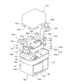
- FIG. 1 is a sectional view showing an example of the entire configuration of an electromagnetic contactor as a switch according to the present invention
- FIG. 2 is an exploded perspective view showing an example of an electromagnetic contactor according to the present invention
- FIG. It is a perspective view which shows a state. 1 to 3, reference numeral 10 denotes an electromagnetic contactor as a switch.
- the electromagnetic contactor 10 includes a contact device 100 in which a contact mechanism is arranged and an electromagnet device 200 that drives the contact device 100. ing.
- the contact device 100 includes an arc extinguishing container 102 that houses the contact mechanism 101.
- the arc extinguishing container 102 has a bowl-shaped metal body 103 that opens a top end of a metal plate material such as aluminum, aluminum alloy, stainless steel or the like formed into a bowl shape by press molding. Yes.
- the arc extinguishing container 102 includes an insulating holding member 105 made of, for example, synthetic resin that holds the pair of fixed contacts 104A and 104B arranged in the bowl-shaped metal body 103.
- the arc-extinguishing container 102 is inserted from the open end surface side of the bowl-shaped metal body 103 and has a lower end surface covering the pair of fixed contacts 104A and 104B and the movable contact 106 arranged so as to be able to contact with and separate from them.
- An open bowl-shaped resin cover 107 is provided.
- the bowl-shaped metal body 103 includes a substantially rectangular bottom plate portion 103a and a rectangular tube portion 103b extending upward from the outer peripheral edge of the bottom plate portion 103a.
- the bottom plate portion 103a is formed with an insertion hole 103c through which a part of a fixed iron core of an electromagnet device 200 described later is inserted at the center.
- the upper part of the insertion hole 103c extends upward through the center of the fixed iron core, and comes into contact with the lower end of the flange part formed on the movable shaft with the movable contact 106 supported by the contact spring at the upper end.
- a positioning piece 111 that regulates the lower end position of the lens is fixed.
- Each of the pair of fixed contacts 104A and 104B is formed symmetrically.
- the pair of fixed contacts 104A and 104B are arranged in the center of the arc extinguishing container 102 and extend downward from the outer end of the contact 104a, with a horizontal contact 104a facing the contact of the movable contact 106.
- a U-shaped bent portion 104b, and a connection terminal portion 104c extending horizontally outward from the other end of the U-shaped bent portion 104b.
- the insulating holding member 105 includes a bottom plate portion 105a disposed in contact with the inner surfaces of the side plate portions 103d and 103e on the short side of the bowl-shaped metal body 103, and the bottom plate portion.
- Contact holding parts 105b and 105c for holding a pair of fixed contacts 104A and 104B formed to face the side plate parts 103d and 103e are provided on the upper surface of 105a.
- each of the contact holding parts 105b and 105c is an inner hook-like shape that extends in the vertical direction and passes through the vertical plate part of the U-shaped bent part 104b of the pair of fixed contacts 104A and 104B and faces each other.
- a portion 121 and an outer flange 122 are provided.
- the inner hook 121 is parallel to the side plates 103d and 103e of the hook metal body 103 while maintaining a predetermined distance, and a central plate 123 extending in an up-and-down direction from the upper edge of the hook metal body 103 is extended to the center plate 123. It is composed of a pair of side plate portions 124 and 125 protruding rightward from the front and rear end portions of the central plate portion 123.
- the outer hook 122 extends in the vertical direction along one of the side plates 103 d and 103 e of the hook metal body 103, and a center plate 126 whose upper end protrudes from the upper end of the hook metal 103 and the center plate 126. It is comprised by a pair of side-plate part 127 and 128 which protrudes to the left from the front-and-back end part.
- the inner flange 121 of the contact holders 105b and 105c is integrally connected by side walls 129 and 130 whose side plates 124 and 125 bulge in the front-rear direction to form a cylindrical part 131. .
- an engagement piece 132 that protrudes outward and engages with the inner surface of the rectangular tube portion 103 b of the bowl-shaped metal body 103 is formed on the lower surface side of the side wall portions 129 and 130.
- an engagement piece 133 that protrudes outward is formed on the side surface of the central plate portion 126 of the outer flange portion 122 of the contact holder holding portions 105b and 105c. This engagement piece 133 is engaged with an engagement recess 134 formed at the upper end on the short side to the rectangular tube portion 103 b of the bowl-shaped metal body 103.
- the pair of fixed contacts 104A and 104B are inserted and held from above by the contact holding portions 105b and 105c.
- the insertion and holding of the fixed contacts 104A and 104B will be described with reference to the fixed contact 104B as shown in FIG.
- the inner vertical plate portion 104b1 in the U-shaped bent portion 104b of the stationary contact 104B is engaged with the center plate portion 123 and the side plate portions 124 and 125 of the inner hook portion 121 of the contact holding portion 105c, Further, the outer vertical plate portion 104b2 in the U-shaped bent portion 104b is inserted from above so as to be engaged with the central plate portion 126 and the side plate portions 127 and 128 of the outer flange portion 122.
- the fixed contact 104A is also inserted and held in the contact holding part 105b in the same manner as described above.
- the resin cover 107 is formed with a peripheral flange portion 107a on the open end surface at the lower end to secure a bonding area with a thick thickness of other portions. Further, the peripheral flange portion 107a has a bottom portion of the U-shaped bent portion 104b of the fixed contacts 104A and 104B at a position facing the fixed contacts 104A and 104B held by the contact holder holding portions 105b and 105c. A notch 107b is formed through which is inserted.
- the movable contact 106 is disposed so that the left and right ends are opposed to the lower side of the contact portion 104a of the fixed contacts 104A and 104B.
- the movable contact 106 is supported by a movable shaft 141 fixed to a movable iron core 212 of an electromagnet device 200 described later.
- the movable shaft 141 has a flange portion 141a protruding outward at the upper end.
- a contact spring 142 that applies a predetermined contact pressure is inserted into the lower end side of the movable contact 106 of the movable shaft 141.
- the movable contact 106 is in a released state, and the contact portions at both ends and the contact portions 104a of the fixed contacts 104A and 104B are separated from each other with a predetermined interval. Further, the movable contact 106 is set so that the contact portions at both ends are in contact with the contact portions 104a of the fixed contacts 104A and 104B with a predetermined contact pressure by the contact spring 142 at the closing position.
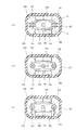
- magnet holding portions 151 and 152 are formed on the above-described insulating holding member 105. These magnet holding portions 151 and 152 are in contact with the contact portions 104a of the fixed contacts 104A and 104B and the movable contact 106 inside the contact holding portions 105b and 105c in the left-right direction and holding the fixed contacts 104A and 104B. It faces the contact part from the side surface side in the front-rear direction. In these magnet holders 151 and 152, arc extinguishing permanent magnets 153 and 154 are inserted and held. The magnet holding portions 151 and 152 are disposed inside the side wall portions 129 and 130. It is covered with the resin cover 107 described above.
- the arc extinguishing permanent magnets 153 and 154 are magnetized so that their opposing surfaces have the same polarity, for example, N pole, in the thickness direction. Further, the arc extinguishing permanent magnets 153 and 154 are set so that both end portions in the left-right direction are slightly inside the ends of the left and right contact portions of the movable contact 106 as shown in FIG. Yes. Arc extinguishing spaces 155 and 156 are formed on the outer sides of the magnet holding portions 151 and 152 in the left-right direction, respectively.
- the arc extinguishing permanent magnets 153 and 154 can be brought close to the movable contact 106.
- the magnetic flux ⁇ generated from the N pole side of both arc extinguishing permanent magnets 153 and 154 is the contact between the contact 104a of the fixed contacts 104A and 104B and the movable contact 106.
- the portion facing the portion 106a is traversed with a large magnetic flux density from the inside to the outside in the left-right direction.
- connection terminal portion 104c of the fixed contact 104A is connected to the power supply source and the fixed contact 104B is connected to the load side, the direction of the current in the applied state is as shown in FIG.
- the fixed contact 104A flows from the fixed contact 104A through the movable contact 106 to the fixed contact 104B.
- the contact portion 104a of the fixed contacts 104A and 104B and the contact portion 106a of the movable contact 106 are connected. An arc is generated between them.
- the Lorentz force F acting on the arc is increased by the magnetic flux ⁇ from the arc extinguishing permanent magnets 153 and 154, and the arc on the arc extinguishing permanent magnet 153 side is increased. It is greatly stretched toward the arc extinguishing space 155 side.
- the arc extinguishing spaces 155 and 156 are formed wide by the thickness of the arc extinguishing permanent magnets 153 and 154, a long arc length can be taken and the arc can be extinguished reliably.
- the electromagnet device 200 includes a U-shaped magnetic yoke 201 that is flat when viewed from the side, and a cylindrical auxiliary yoke 203 is fixed to the center of the bottom plate portion 202 of the magnetic yoke 201.
- a spool 204 as a plunger driving unit is disposed outside the cylindrical auxiliary yoke 203.
- the spool 204 includes a central cylindrical portion 205 that passes through the cylindrical auxiliary yoke 203, a lower flange portion 206 that protrudes radially outward from the lower end portion of the central cylindrical portion 205, and a little more than the upper end of the central cylindrical portion 205.
- the upper flange portion 207 protrudes radially outward from the lower side.
- An exciting coil 208 is wound around a storage space formed by the central cylindrical portion 205, the lower flange portion 206, and the upper flange portion 207.
- the upper magnetic yoke 210 is fixed between the upper ends of the magnetic yoke 201 serving as the open end.
- the upper magnetic yoke 210 is formed with a through hole 210 a facing the central cylindrical portion 205 of the spool 204 at the central portion.
- a fixed iron core 211 is fixedly disposed on the upper side of the central cylindrical portion 205 of the spool 204, and a movable iron core 212 is disposed below the fixed iron core 211 with a predetermined distance.
- a return spring 213 is inserted between the fixed iron core 211 and the movable iron core 212, and the movable iron core 212 is pressed downward by the return spring 213.
- a movable shaft 141 is fixed to the movable iron core 212. The movable shaft 141 protrudes into the contact device 100 through the central shaft hole of the fixed iron core 211, and the movable contact 106 is held by a contact spring 142 at the upper end thereof.
- the fixed iron core 211 and the movable iron core 212 are covered with a bottomed cylindrical cap 215 whose upper end is opened.
- a flange portion 216 formed by extending in the radial direction at the open end of the cap 215 is sealed and joined to the lower surface of the bowl-shaped metal body 103 by brazing, welding, or the like.
- a sealed container is formed in which the arc extinguishing container 102 and the cap 215 are communicated with each other through the insertion hole 103 c of the bowl-shaped metal body 103.
- a gas such as hydrogen gas, nitrogen gas, a mixed gas of hydrogen and nitrogen, air, or SF 6 is sealed in a sealed container formed by the arc extinguishing container 102 and the cap 215.
- the spool 204 is disposed in the magnetic yoke 201 of the electromagnet device 200. Then, with the movable iron core 212 and the fixed iron core 211 inserted into the cap 215 via the return spring 213, the cap 215 is brazed to the bowl-shaped metal body 103 and fixed by welding or the like. At this time, the fixed iron core 211 is fixed in the insertion hole 103 c of the bowl-shaped metal body 103, and the lower position of the movable shaft 141 is defined by fixing the positioning piece 111 at the center of the bowl-shaped metal body 103.
- the insulating holding member 105 is inserted and held in the bowl-shaped metal body 103.
- the U-shaped bent portions 104b of the pair of fixed contacts 104A and 104B are inserted and held in the contact holding portions 105b and 105c of the insulating holding member 105 so that the contact portions 104a are inside.
- the contact portions 104a of the pair of fixed contacts 104A and 104B face the contact portions 106a of the movable contact 106 from above.
- an adhesive is injected into the U-shaped bent portions 104b of the pair of fixed contacts 104A and 104B, and an adhesive is applied to the lower surface side of the peripheral flange portion 107a of the resin cover 107.
- the resin cover 107 is surrounded by the bottom plate portion 103a of the bowl-shaped metal body 103 from above so that the bottom plate portion of the U-shaped bent portion 104b of the pair of fixed contacts 104A and 104B is inserted into the notch portion 107b.
- the part 107a is brought into contact.
- the peripheral flange portion 107a and the bottom plate portion 103a of the bowl-shaped metal body 103 are bonded by the adhesive, and the bottom plate portion of the U-shaped bent portion 104b of the pair of fixed contacts 104A and 104B and the resin
- the notch 107b of the cover 107 is bonded. Therefore, a sealed arc extinguishing chamber is formed by the bowl-shaped metal body 103, the resin cover 107, and the cap 215.
- a gas such as hydrogen gas, nitrogen gas, a mixed gas of hydrogen and nitrogen, air, SF 6 or the like is injected from a gas injection hole (not shown) formed in the resin cover 107. Seal the injection hole.
- the electromagnetic contactor 10 can be comprised.
- a power supply source that supplies a large current is connected to the connection terminal portion 104c of the fixed contact 104A, and a load is applied to the connection terminal portion 104c of the fixed contact 104B.
- the exciting coil 208 in the electromagnet device 200 is in a non-excited state and the electromagnet device 200 is in a released state in which the exciting force that raises the movable iron core 212 is not generated.
- the movable iron core 212 is urged by the return spring 213 in a direction away from the fixed iron core 211.
- the contact portion 106a of the movable contact 106 of the contact mechanism 101 connected to the movable iron core 212 via the movable shaft 141 is spaced downward from the contact portion 104a of the fixed contacts 104A and 104B by a predetermined distance. .
- the current path between the stationary contacts 104A and 104B is in an interrupted state, and the contact mechanism 101 is in an open state.
- the urging force of the return spring 213 acts on the movable iron core 212, so that the movable iron core 212 does not inadvertently drop due to external vibrations or shocks, so that malfunction can be assured. Can be prevented.
- the movable iron core 212 rises quickly against the urging force of the return spring 213.
- the rising of the movable iron core 212 is stopped when the upper end of the movable iron core 212 contacts the lower end of the fixed iron core 211.
- the movable contact 106 connected to the movable iron core 212 via the movable shaft 141 is also raised, and the contact portion 106a thereof is the contact portion 104a of the fixed contacts 104A and 104B.
- the fixed contacts 104A and 104B have an L-shaped portion formed by the contact portion 104a and the U-shaped bent portion 104b, so that the upper plate portion 116 and the lower plate portion 118 are formed. In other words, a current in the reverse direction flows between the movable contact 106 and the movable contact 106 facing the same.
- the magnetic flux generated by the current flowing through the vertical plate portion of the L-shaped portion of the stationary contacts 104A and 104B can be applied to the contact portion between the stationary contacts 104A and 104B and the movable contact 106.
- the Lorentz force which resists an electromagnetic repulsive force can be generated by increasing the magnetic flux density at the contact portion between the fixed contacts 104A and 104B and the movable contact 106.
- the arc generation portion of the contact portion 104a of the fixed contact 104B and the contact portion 106a of the movable contact 106 crosses from the inside to the outside in the longitudinal direction of the movable contact 106 and reaches the S pole to form a magnetic field. Accordingly, the magnetic fluxes of the arc extinguishing permanent magnets 153 and 154 are both between the contact part 104a of the fixed contact 104A and the contact part 106a of the movable contact 106, and between the contact part 104a of the fixed contact 104B and the contact of the movable contact 1060. The portions 1060a cross in the opposite directions in the longitudinal direction of the movable contact 106.
- the arc generated between the contact portion 104a of the fixed contact 104A and the contact portion 106a of the movable contact 106 due to the Lorentz force F passes through the arc extinguishing space 155 from the side surface of the contact portion 104a of the fixed contact 104A. It is greatly stretched so as to reach the upper surface side of the movable contact 106 and is extinguished. Further, in the arc extinguishing space 155, the magnetic flux is below and above the lower side and the upper side with respect to the direction of the magnetic flux between the contact portion 104 a of the fixed contact 104 ⁇ / b> A and the contact portion 106 a of the movable contact 106. Will tilt.
- the arc stretched in the arc extinguishing space 155 by the tilted magnetic flux is further stretched in the direction of the corner of the arc extinguishing space 155, the arc length can be increased, and good interruption performance can be obtained. .
- the current I flows from the movable contact 106 side to the fixed contact 104B side, and the magnetic flux ⁇ . Is the right direction from the inside to the outside.
- the arc extinguishing space 155 is directed to the arc extinguishing space 155 side perpendicular to the longitudinal direction of the movable contact 106 and perpendicular to the opening / closing direction of the contact portion 104a of the fixed contact 104B and the movable contact 106.
- a large Lorentz force F acts.
- the arc generated between the contact portion 104a of the fixed contact 104B and the movable contact 106 due to the Lorentz force F passes through the arc extinguishing space 155 from the upper surface side of the movable contact 106 to the fixed contact 104B. It is greatly stretched to reach the side and extinguished. Further, in the arc extinguishing space 155, as described above, on the lower side and the upper side, the lower side and the upper side with respect to the direction of the magnetic flux between the contact part 104a of the stationary contact 104B and the contact part 106a of the movable contact 106 and The magnetic flux is inclined upward.
- the arc stretched in the arc extinguishing space 155 by the tilted magnetic flux is further stretched in the direction of the corner of the arc extinguishing space 155, the arc length can be increased, and good interruption performance can be obtained.
- the electromagnetic contactor 10 is turned on and the regenerative current is flowing from the load side to the DC power source side and the release state is set, the direction of the current in FIG. 4B is reversed. Therefore, the same arc extinguishing function is exhibited except that the Lorentz force F acts on the arc extinguishing space 156 side and the arc is extended to the arc extinguishing space 156 side.
- the arc extinguishing permanent magnets 153 and 154 are disposed in the magnet holding portions 151 and 152 formed in the insulating holding member 105, the arc directly contacts the arc extinguishing permanent magnets 153 and 154. There is nothing. For this reason, the magnetic characteristics of the arc extinguishing permanent magnets 153 and 154 can be stably maintained, and the interruption performance can be stabilized.
- the bowl-shaped metal body 103 and the resin cover 107 are fixed by an adhesive, and similarly, the resin cover 107 and the U-shaped bent portions 104b of the pair of fixed contacts 104A and 104B are also fixed by an adhesive. For this reason, the bowl-shaped metal body 103 and the resin cover 107 can be fixed without performing brazing, welding, or the like. Therefore, since it is not necessary to apply heat to the fixing of the bowl-shaped metal body 103 and the resin cover 107, good sealing can be performed without causing thermal deformation or thermal stress.
- the insulation holding member 105b and the resin cover 107 can cover and insulate the inner peripheral surface of the bowl-shaped metal body 103, there is no short circuit of the arc when the current is interrupted, and the current can be reliably interrupted. Further, the insulating holding member 105 and the resin cover 107 can perform the insulating function, the positioning function of the arc extinguishing permanent magnets 153 and 154, and the arc extinguishing permanent magnets 153 and 154 from the arc. Cost can be reduced.
- the arc extinguishing container 102 includes the pair of fixed contacts disposed on the upper surface side of the bowl-shaped metal body 103 and the bottom plate portion 103a of the bowl-shaped metal body 103.
- the insulating holding member 105 that holds 104A and 104B, the pair of fixed contacts 104A and 104B, the movable contact 106, and the resin cover 107 that covers the arc extinguishing permanent magnets 153 and 154 are configured.
- the cage metal body 103 and the resin cover 107 are fixed with an adhesive, and the resin cover 107 and the pair of fixed contacts 104A and 104B are bonded and held with an adhesive.
- the bowl-shaped metal body 103 and the resin cover 107 can be bonded in an airtight state with an adhesive. Therefore, it is not necessary to apply expensive ceramics as the arc extinguishing container, and the manufacturing cost of the arc extinguishing container 102 can be greatly reduced. In addition, in order to maintain airtightness, it is not necessary to perform brazing, welding, or the like, and it is only necessary to fix with an adhesive, so that thermal deformation and generation of thermal stress can be reliably prevented.
- the contact portion 104a, the U-shaped bent portion 104b, and the connection terminal portion 104c are integrally formed with the pair of fixed contacts 104A and 104B, the fixed contacts 104A and 104B are manufactured at low cost. Can be manufactured easily.
- the arc extinguishing permanent magnets 153 and 154 are arranged inside the resin cover 107, the magnetic flux density across the arc can be increased, and the arc extinguishing spaces 155 and 156 are used for arc extinguishing.
- the permanent magnets 153 and 154 can be formed wider than the thickness of the permanent magnets 153, can take a long arc length, and can reliably extinguish the arc.
- the movable contact 106 of the contact device 100 can be moved by the electromagnet device 200, and an electromagnetic contactor can be easily configured.
- the case where the fixed contacts 104A and 104B constituting the contact mechanism 101 are formed in an L shape in the vicinity of the movable contact 106 will be described.
- the present invention is configured according to the above embodiment.
- the movable contact 106 can be formed in a C shape so as to be sandwiched between the upper and lower sides, and a contact mechanism having any other configuration can be applied.
- the sealed container was comprised with the arc-extinguishing container 102 and the cap 215 and gas was enclosed in this sealed container, it was not limited to this,
- block is not limited to this. If it is low, gas filling may be omitted.
- the arc extinguishing permanent magnets 153 and 154 are arranged on the inner peripheral surface of the resin cover 107 has been described.
- the present invention is not limited to the above configuration, and arc extinguishing permanent magnets may be disposed on the outer peripheral surface of the resin cover 107, and further, arc extinguishing permanent magnets 153 and 154 are omitted. You may do it.
- the case where the electromagnet device 200 has the U-shaped magnetic yoke 201 has been described.
- a bottomed cylindrical magnetic yoke may be applied. Any configuration can be applied as long as the fixed contacts 104A and 104B can be moved toward and away from the fixed contacts 104A and 104B.
- the present invention is applied to an electromagnetic contactor.
- the present invention is not limited to this, and the present invention is applied to a switch having an arc extinguishing container such as an electromagnetic relay or a switch. can do.
- the arc-extinguishing container that seals the contact mechanism in a state of surrounding the contact mechanism does not require heating such as projection welding, laser welding, brazing, or the like, and is simply performed with an adhesive without using a joining process. It is possible to provide a switch such as an electromagnetic contactor that can be easily formed by simply bonding the resin cover to the resin cover.
- Electromagnetic contactor 11 ... Exterior insulation container, 100 ... Contact apparatus, 101 ... Contact mechanism, 102 ... Arc-extinguishing container, 103 ... Saddle-shaped metal body, 104A, 104B ... Fixed contact, 104a ... Contact part, 104b ... U-shaped bent part, 104c ... connection terminal part, 105 ... insulating holding member, 105b, 105c ... contact holding part, 106 ... movable contact, 106a ... contact part, 107 ... resin cover, 107a ... peripheral flange part, 107b ... Notch part, 141 ... Movable shaft, 142 ...
- Electromagnet device 201 ... Magnetic yoke 203 ... Cylindric auxiliary yoke 204 ... Spool 208 ... Excitation coil 210 ... Upper magnetic yoke 211 ... Fixed iron core 212 ... Movable iron core 21 ... return spring, 215 ... cap
Landscapes
- Physics & Mathematics (AREA)
- Electromagnetism (AREA)
- Arc-Extinguishing Devices That Are Switches (AREA)
- Contacts (AREA)
Abstract
Cette invention concerne un commutateur qui facilite la formation d'une enceinte étanche. Ledit commutateur contient, à l'intérieur d'une enceinte d'extinction d'arc (102) : une paire de contacts fixes (104A, 104B) situés à une distance prédéterminée l'un de l'autre ; et un contact mobile (106) disposé de façon à pouvoir être mis en contact/hors contact avec la paire de contacts fixes. L'enceinte d'extinction d'arc (102) comprend : un corps métallique en forme de cuve (103) avec une extrémité supérieure ouverte ; un élément de support isolant (105) qui supporte la paire de contacts fixes qui sont disposés sur le côté formant surface intérieure du corps métallique en forme de cuve, de manière opposée au contact mobile ; et un couvercle en résine en forme de cuve (107) qui présente une extrémité inférieure ouverte et recouvre la paire de contacts fixes et le contact mobile sur le côté ouvert du corps métallique en forme de cuve. Un adhésif est utilisé pour sceller le périmètre de l'extrémité ouverte du couvercle en résine (107) sur la surface inférieure du corps métallique en forme de cuve (103).
Priority Applications (4)
| Application Number | Priority Date | Filing Date | Title |
|---|---|---|---|
| CN201380019152.XA CN104205283B (zh) | 2012-04-13 | 2013-04-11 | 开关 |
| EP13775676.3A EP2838100A4 (fr) | 2012-04-13 | 2013-04-11 | Commutateur |
| KR1020147028319A KR20150004805A (ko) | 2012-04-13 | 2013-04-11 | 개폐기 |
| US14/504,958 US9508508B2 (en) | 2012-04-13 | 2014-10-02 | Switch including an arc extinguishing container with a metal body and a resin cover |
Applications Claiming Priority (2)
| Application Number | Priority Date | Filing Date | Title |
|---|---|---|---|
| JP2012-092449 | 2012-04-13 | ||
| JP2012092449A JP5965197B2 (ja) | 2012-04-13 | 2012-04-13 | 開閉器 |
Related Child Applications (1)
| Application Number | Title | Priority Date | Filing Date |
|---|---|---|---|
| US14/504,958 Continuation US9508508B2 (en) | 2012-04-13 | 2014-10-02 | Switch including an arc extinguishing container with a metal body and a resin cover |
Publications (1)
| Publication Number | Publication Date |
|---|---|
| WO2013153816A1 true WO2013153816A1 (fr) | 2013-10-17 |
Family
ID=49327400
Family Applications (1)
| Application Number | Title | Priority Date | Filing Date |
|---|---|---|---|
| PCT/JP2013/002472 WO2013153816A1 (fr) | 2012-04-13 | 2013-04-11 | Commutateur |
Country Status (6)
| Country | Link |
|---|---|
| US (1) | US9508508B2 (fr) |
| EP (1) | EP2838100A4 (fr) |
| JP (1) | JP5965197B2 (fr) |
| KR (1) | KR20150004805A (fr) |
| CN (1) | CN104205283B (fr) |
| WO (1) | WO2013153816A1 (fr) |
Families Citing this family (16)
| Publication number | Priority date | Publication date | Assignee | Title |
|---|---|---|---|---|
| CN108417448B (zh) | 2013-06-28 | 2021-03-05 | 松下知识产权经营株式会社 | 触点装置以及搭载有该触点装置的电磁继电器 |
| JP6265657B2 (ja) * | 2013-08-26 | 2018-01-24 | 富士通コンポーネント株式会社 | 電磁継電器 |
| JP6202943B2 (ja) * | 2013-08-26 | 2017-09-27 | 富士通コンポーネント株式会社 | 電磁継電器 |
| JP6548905B2 (ja) * | 2015-02-06 | 2019-07-24 | 富士通コンポーネント株式会社 | スイッチ |
| KR20170009348A (ko) | 2015-07-16 | 2017-01-25 | 엘에스산전 주식회사 | 영구자석을 포함한 전기자동차용 릴레이 및 그 제조방법 |
| KR101943365B1 (ko) * | 2015-10-14 | 2019-01-29 | 엘에스산전 주식회사 | 직류 릴레이 |
| JP6274229B2 (ja) * | 2016-01-27 | 2018-02-07 | 富士電機機器制御株式会社 | 接点装置及びこれを使用した電磁接触器 |
| JP6926738B2 (ja) * | 2017-07-04 | 2021-08-25 | オムロン株式会社 | 電磁継電器 |
| JP2019083174A (ja) * | 2017-10-31 | 2019-05-30 | オムロン株式会社 | 電磁継電器 |
| KR102324514B1 (ko) * | 2018-08-31 | 2021-11-10 | 엘에스일렉트릭 (주) | 직류 릴레이 |
| KR20200000311A (ko) * | 2018-08-31 | 2020-01-02 | 엘에스산전 주식회사 | 직류 릴레이 |
| US11764010B2 (en) * | 2018-10-19 | 2023-09-19 | Te Connectivity Solutions Gmbh | Contactor with arc suppressor |
| KR102652524B1 (ko) * | 2018-11-09 | 2024-03-29 | 샤먼 홍파 일렉트릭 파워 컨트롤즈 컴퍼니 리미티드 | 단락전류 방지용 직류 릴레이 |
| JP2021044211A (ja) * | 2019-09-13 | 2021-03-18 | オムロン株式会社 | 電磁継電器 |
| US11688574B2 (en) * | 2021-09-13 | 2023-06-27 | Song Chuan Precision Co., Ltd. | Electromagnetic relay |
| JP2023156771A (ja) | 2022-04-13 | 2023-10-25 | オムロン株式会社 | 電磁継電器 |
Citations (6)
| Publication number | Priority date | Publication date | Assignee | Title |
|---|---|---|---|---|
| JPH10125196A (ja) * | 1996-07-31 | 1998-05-15 | Matsushita Electric Works Ltd | 封止接点装置 |
| JP2005015773A (ja) | 2003-06-05 | 2005-01-20 | Omron Corp | 端子のシール構造およびそれに用いるシール材 |
| JP2006019148A (ja) * | 2004-07-01 | 2006-01-19 | Matsushita Electric Works Ltd | 電磁開閉装置 |
| JP2010267470A (ja) * | 2009-05-14 | 2010-11-25 | Nippon Soken Inc | 電磁継電器 |
| JP2011228087A (ja) * | 2010-04-19 | 2011-11-10 | Nippon Soken Inc | 電磁継電器 |
| JP2012054047A (ja) * | 2010-08-31 | 2012-03-15 | Fuji Electric Fa Components & Systems Co Ltd | 電磁開閉器 |
Family Cites Families (14)
| Publication number | Priority date | Publication date | Assignee | Title |
|---|---|---|---|---|
| JPH07335105A (ja) * | 1994-06-13 | 1995-12-22 | Fuji Electric Co Ltd | 電磁接触器 |
| US5892194A (en) | 1996-03-26 | 1999-04-06 | Matsushita Electric Works, Ltd. | Sealed contact device with contact gap adjustment capability |
| JP2005026182A (ja) * | 2003-07-02 | 2005-01-27 | Matsushita Electric Works Ltd | 電磁開閉装置 |
| JP4321256B2 (ja) * | 2003-12-22 | 2009-08-26 | オムロン株式会社 | 電磁継電器 |
| JP2007305468A (ja) * | 2006-05-12 | 2007-11-22 | Omron Corp | 電磁継電器 |
| WO2008033349A2 (fr) * | 2006-09-11 | 2008-03-20 | Gigavac, Inc. | Contacteur hermétique |
| CA2718970C (fr) | 2008-03-19 | 2013-12-10 | Panasonic Electric Works Co., Ltd. | Dispositif de contact |
| KR101004465B1 (ko) * | 2008-09-05 | 2010-12-31 | 엘에스산전 주식회사 | 계전기 |
| JP2010192416A (ja) * | 2009-01-21 | 2010-09-02 | Panasonic Electric Works Co Ltd | 封止接点装置 |
| WO2011115050A1 (fr) | 2010-03-15 | 2011-09-22 | オムロン株式会社 | Dispositif de commutation à contact |
| KR101086907B1 (ko) | 2010-10-15 | 2011-11-25 | 엘에스산전 주식회사 | 계전기 |
| JP5809443B2 (ja) * | 2011-05-19 | 2015-11-10 | 富士電機株式会社 | 接点機構及びこれを使用した電磁接触器 |
| JP5990028B2 (ja) | 2012-04-13 | 2016-09-07 | 富士電機機器制御株式会社 | 接点装置及びこれを使用した電磁開閉器 |
| JP5981760B2 (ja) * | 2012-04-27 | 2016-08-31 | 富士電機株式会社 | 電磁開閉器 |
-
2012
- 2012-04-13 JP JP2012092449A patent/JP5965197B2/ja not_active Expired - Fee Related
-
2013
- 2013-04-11 EP EP13775676.3A patent/EP2838100A4/fr not_active Withdrawn
- 2013-04-11 CN CN201380019152.XA patent/CN104205283B/zh not_active Expired - Fee Related
- 2013-04-11 KR KR1020147028319A patent/KR20150004805A/ko not_active Application Discontinuation
- 2013-04-11 WO PCT/JP2013/002472 patent/WO2013153816A1/fr active Application Filing
-
2014
- 2014-10-02 US US14/504,958 patent/US9508508B2/en not_active Expired - Fee Related
Patent Citations (6)
| Publication number | Priority date | Publication date | Assignee | Title |
|---|---|---|---|---|
| JPH10125196A (ja) * | 1996-07-31 | 1998-05-15 | Matsushita Electric Works Ltd | 封止接点装置 |
| JP2005015773A (ja) | 2003-06-05 | 2005-01-20 | Omron Corp | 端子のシール構造およびそれに用いるシール材 |
| JP2006019148A (ja) * | 2004-07-01 | 2006-01-19 | Matsushita Electric Works Ltd | 電磁開閉装置 |
| JP2010267470A (ja) * | 2009-05-14 | 2010-11-25 | Nippon Soken Inc | 電磁継電器 |
| JP2011228087A (ja) * | 2010-04-19 | 2011-11-10 | Nippon Soken Inc | 電磁継電器 |
| JP2012054047A (ja) * | 2010-08-31 | 2012-03-15 | Fuji Electric Fa Components & Systems Co Ltd | 電磁開閉器 |
Non-Patent Citations (1)
| Title |
|---|
| See also references of EP2838100A4 |
Also Published As
| Publication number | Publication date |
|---|---|
| EP2838100A4 (fr) | 2015-12-02 |
| JP2013222560A (ja) | 2013-10-28 |
| JP5965197B2 (ja) | 2016-08-03 |
| KR20150004805A (ko) | 2015-01-13 |
| CN104205283B (zh) | 2016-06-22 |
| CN104205283A (zh) | 2014-12-10 |
| US20150022296A1 (en) | 2015-01-22 |
| US9508508B2 (en) | 2016-11-29 |
| EP2838100A1 (fr) | 2015-02-18 |
Similar Documents
| Publication | Publication Date | Title |
|---|---|---|
| JP5965197B2 (ja) | 開閉器 | |
| EP2711965B1 (fr) | Contacteur électromagnétique | |
| JP5727862B2 (ja) | 電磁接触器 | |
| JP5689741B2 (ja) | 電磁接触器 | |
| JP5684649B2 (ja) | 電磁接触器 | |
| JP5876270B2 (ja) | 電磁接触器 | |
| JP5914065B2 (ja) | 開閉器 | |
| WO2013051263A1 (fr) | Dispositif de contact et contacteur magnétique le mettant en œuvre | |
| WO2013183226A1 (fr) | Contacteur électromagnétique | |
| JP5727860B2 (ja) | 電磁接触器 | |
| JP2012243584A (ja) | 電磁接触器 | |
| JP5864902B2 (ja) | 電磁接触器の消弧室組立方法 | |
| WO2012157171A1 (fr) | Contacteur électromagnétique | |
| JP2013246873A (ja) | 接点装置 | |
| JP2012199113A (ja) | 接点装置及び電磁開閉器 | |
| JP7259670B2 (ja) | 電磁接触器 | |
| JP7259669B2 (ja) | 電磁接触器 | |
| JP2013127890A (ja) | 電磁継電器 |
Legal Events
| Date | Code | Title | Description |
|---|---|---|---|
| 121 | Ep: the epo has been informed by wipo that ep was designated in this application |
Ref document number: 13775676 Country of ref document: EP Kind code of ref document: A1 |
|
| WWE | Wipo information: entry into national phase |
Ref document number: 2013775676 Country of ref document: EP |
|
| ENP | Entry into the national phase |
Ref document number: 20147028319 Country of ref document: KR Kind code of ref document: A |
|
| NENP | Non-entry into the national phase |
Ref country code: DE |