WO2013150828A1 - めっき処理装置、めっき処理方法および記憶媒体 - Google Patents
めっき処理装置、めっき処理方法および記憶媒体 Download PDFInfo
- Publication number
- WO2013150828A1 WO2013150828A1 PCT/JP2013/054503 JP2013054503W WO2013150828A1 WO 2013150828 A1 WO2013150828 A1 WO 2013150828A1 JP 2013054503 W JP2013054503 W JP 2013054503W WO 2013150828 A1 WO2013150828 A1 WO 2013150828A1
- Authority
- WO
- WIPO (PCT)
- Prior art keywords
- substrate
- plating
- discharge
- cleaning liquid
- liquid
- Prior art date
- Legal status (The legal status is an assumption and is not a legal conclusion. Google has not performed a legal analysis and makes no representation as to the accuracy of the status listed.)
- Ceased
Links
Images








Classifications
-
- C—CHEMISTRY; METALLURGY
- C23—COATING METALLIC MATERIAL; COATING MATERIAL WITH METALLIC MATERIAL; CHEMICAL SURFACE TREATMENT; DIFFUSION TREATMENT OF METALLIC MATERIAL; COATING BY VACUUM EVAPORATION, BY SPUTTERING, BY ION IMPLANTATION OR BY CHEMICAL VAPOUR DEPOSITION, IN GENERAL; INHIBITING CORROSION OF METALLIC MATERIAL OR INCRUSTATION IN GENERAL
- C23C—COATING METALLIC MATERIAL; COATING MATERIAL WITH METALLIC MATERIAL; SURFACE TREATMENT OF METALLIC MATERIAL BY DIFFUSION INTO THE SURFACE, BY CHEMICAL CONVERSION OR SUBSTITUTION; COATING BY VACUUM EVAPORATION, BY SPUTTERING, BY ION IMPLANTATION OR BY CHEMICAL VAPOUR DEPOSITION, IN GENERAL
- C23C18/00—Chemical coating by decomposition of either liquid compounds or solutions of the coating forming compounds, without leaving reaction products of surface material in the coating; Contact plating
- C23C18/16—Chemical coating by decomposition of either liquid compounds or solutions of the coating forming compounds, without leaving reaction products of surface material in the coating; Contact plating by reduction or substitution, e.g. electroless plating
- C23C18/1601—Process or apparatus
- C23C18/1619—Apparatus for electroless plating
-
- C—CHEMISTRY; METALLURGY
- C23—COATING METALLIC MATERIAL; COATING MATERIAL WITH METALLIC MATERIAL; CHEMICAL SURFACE TREATMENT; DIFFUSION TREATMENT OF METALLIC MATERIAL; COATING BY VACUUM EVAPORATION, BY SPUTTERING, BY ION IMPLANTATION OR BY CHEMICAL VAPOUR DEPOSITION, IN GENERAL; INHIBITING CORROSION OF METALLIC MATERIAL OR INCRUSTATION IN GENERAL
- C23C—COATING METALLIC MATERIAL; COATING MATERIAL WITH METALLIC MATERIAL; SURFACE TREATMENT OF METALLIC MATERIAL BY DIFFUSION INTO THE SURFACE, BY CHEMICAL CONVERSION OR SUBSTITUTION; COATING BY VACUUM EVAPORATION, BY SPUTTERING, BY ION IMPLANTATION OR BY CHEMICAL VAPOUR DEPOSITION, IN GENERAL
- C23C18/00—Chemical coating by decomposition of either liquid compounds or solutions of the coating forming compounds, without leaving reaction products of surface material in the coating; Contact plating
- C23C18/16—Chemical coating by decomposition of either liquid compounds or solutions of the coating forming compounds, without leaving reaction products of surface material in the coating; Contact plating by reduction or substitution, e.g. electroless plating
- C23C18/1601—Process or apparatus
- C23C18/1633—Process of electroless plating
- C23C18/1675—Process conditions
-
- C—CHEMISTRY; METALLURGY
- C23—COATING METALLIC MATERIAL; COATING MATERIAL WITH METALLIC MATERIAL; CHEMICAL SURFACE TREATMENT; DIFFUSION TREATMENT OF METALLIC MATERIAL; COATING BY VACUUM EVAPORATION, BY SPUTTERING, BY ION IMPLANTATION OR BY CHEMICAL VAPOUR DEPOSITION, IN GENERAL; INHIBITING CORROSION OF METALLIC MATERIAL OR INCRUSTATION IN GENERAL
- C23C—COATING METALLIC MATERIAL; COATING MATERIAL WITH METALLIC MATERIAL; SURFACE TREATMENT OF METALLIC MATERIAL BY DIFFUSION INTO THE SURFACE, BY CHEMICAL CONVERSION OR SUBSTITUTION; COATING BY VACUUM EVAPORATION, BY SPUTTERING, BY ION IMPLANTATION OR BY CHEMICAL VAPOUR DEPOSITION, IN GENERAL
- C23C18/00—Chemical coating by decomposition of either liquid compounds or solutions of the coating forming compounds, without leaving reaction products of surface material in the coating; Contact plating
- C23C18/16—Chemical coating by decomposition of either liquid compounds or solutions of the coating forming compounds, without leaving reaction products of surface material in the coating; Contact plating by reduction or substitution, e.g. electroless plating
- C23C18/18—Pretreatment of the material to be coated
- C23C18/1803—Pretreatment of the material to be coated of metallic material surfaces or of a non-specific material surfaces
- C23C18/1824—Pretreatment of the material to be coated of metallic material surfaces or of a non-specific material surfaces by chemical pretreatment
- C23C18/1837—Multistep pretreatment
- C23C18/1844—Multistep pretreatment with use of organic or inorganic compounds other than metals, first
-
- H—ELECTRICITY
- H10—SEMICONDUCTOR DEVICES; ELECTRIC SOLID-STATE DEVICES NOT OTHERWISE PROVIDED FOR
- H10P—GENERIC PROCESSES OR APPARATUS FOR THE MANUFACTURE OR TREATMENT OF DEVICES COVERED BY CLASS H10
- H10P14/00—Formation of materials, e.g. in the shape of layers or pillars
- H10P14/40—Formation of materials, e.g. in the shape of layers or pillars of conductive or resistive materials
- H10P14/46—Formation of materials, e.g. in the shape of layers or pillars of conductive or resistive materials using a liquid
-
- H—ELECTRICITY
- H10—SEMICONDUCTOR DEVICES; ELECTRIC SOLID-STATE DEVICES NOT OTHERWISE PROVIDED FOR
- H10W—GENERIC PACKAGES, INTERCONNECTIONS, CONNECTORS OR OTHER CONSTRUCTIONAL DETAILS OF DEVICES COVERED BY CLASS H10
- H10W20/00—Interconnections in chips, wafers or substrates
- H10W20/01—Manufacture or treatment
- H10W20/031—Manufacture or treatment of conductive parts of the interconnections
- H10W20/032—Manufacture or treatment of conductive parts of the interconnections of conductive barrier, adhesion or liner layers
- H10W20/042—Manufacture or treatment of conductive parts of the interconnections of conductive barrier, adhesion or liner layers the barrier, adhesion or liner layers being seed or nucleation layers
- H10W20/044—Manufacture or treatment of conductive parts of the interconnections of conductive barrier, adhesion or liner layers the barrier, adhesion or liner layers being seed or nucleation layers for electroless plating
-
- H—ELECTRICITY
- H10—SEMICONDUCTOR DEVICES; ELECTRIC SOLID-STATE DEVICES NOT OTHERWISE PROVIDED FOR
- H10W—GENERIC PACKAGES, INTERCONNECTIONS, CONNECTORS OR OTHER CONSTRUCTIONAL DETAILS OF DEVICES COVERED BY CLASS H10
- H10W20/00—Interconnections in chips, wafers or substrates
- H10W20/01—Manufacture or treatment
- H10W20/031—Manufacture or treatment of conductive parts of the interconnections
- H10W20/032—Manufacture or treatment of conductive parts of the interconnections of conductive barrier, adhesion or liner layers
- H10W20/052—Manufacture or treatment of conductive parts of the interconnections of conductive barrier, adhesion or liner layers by treatments not introducing additional elements therein
-
- H—ELECTRICITY
- H10—SEMICONDUCTOR DEVICES; ELECTRIC SOLID-STATE DEVICES NOT OTHERWISE PROVIDED FOR
- H10W—GENERIC PACKAGES, INTERCONNECTIONS, CONNECTORS OR OTHER CONSTRUCTIONAL DETAILS OF DEVICES COVERED BY CLASS H10
- H10W20/00—Interconnections in chips, wafers or substrates
- H10W20/01—Manufacture or treatment
- H10W20/031—Manufacture or treatment of conductive parts of the interconnections
- H10W20/056—Manufacture or treatment of conductive parts of the interconnections by filling conductive material into holes, grooves or trenches
-
- H—ELECTRICITY
- H10—SEMICONDUCTOR DEVICES; ELECTRIC SOLID-STATE DEVICES NOT OTHERWISE PROVIDED FOR
- H10P—GENERIC PROCESSES OR APPARATUS FOR THE MANUFACTURE OR TREATMENT OF DEVICES COVERED BY CLASS H10
- H10P70/00—Cleaning of wafers, substrates or parts of devices
- H10P70/20—Cleaning during device manufacture
- H10P70/27—Cleaning during device manufacture during, before or after processing of conductive materials, e.g. polysilicon or amorphous silicon layers
Definitions
- the present invention is a recess formed in the insulating layer, the inner surface of which is provided with a plating solution containing copper and a metal film that can be plated and has a barrier property against copper,
- the present invention relates to a plating apparatus, a plating method, and a storage medium that perform plating.
- wiring for forming a circuit is formed on a substrate such as a semiconductor wafer or a liquid crystal substrate for forming a semiconductor device.
- a damascene method or the like in which concave portions such as vias and trenches for embedding a wiring material such as copper are formed in the insulating layer of the substrate and the wiring material is embedded in the concave portions.
- a barrier is provided between the inner surface of the concave portion of the insulating layer and the wiring formed in the concave portion for the purpose of preventing diffusion of atoms constituting the wiring material into the insulating layer and improving adhesion.
- a membrane is provided.
- barrier films include barrier films containing tantalum such as Ta films and TaN films, and barrier films containing titanium such as Ti films and TiN films.
- a seed film is provided between the barrier film and the wiring to facilitate embedding of the wiring material.
- Patent Document 1 a barrier film containing ruthenium is formed on the inner surface of the recess by sputtering, then a seed film containing ruthenium and copper is formed on the barrier film by sputtering, and then copper is plated in the recess by plating.
- a method of embedding in is proposed.
- the diameter of the recess for embedding the wiring material has been reduced, and for this reason, the aspect ratio of the recess has been increased compared to the conventional case.
- the wiring structure is becoming more complicated.
- a wiring having a different width depending on the position in the depth direction of the recess is used.
- a wiring whose width at the top is narrower than that at the bottom is used.
- the sputtering method generally used for forming the seed film is a method having a large directivity. For this reason, when the aspect ratio of a recessed part is large, or when the structure of a recessed part is complicated, it is difficult to form a seed film enough even to the lower part of a recessed part.
- An object of the present invention is to provide a plating apparatus, a plating method, and a storage medium that can effectively solve such problems.
- the present invention is a recess formed in the insulating layer, the inner surface of which is provided with a plating solution containing copper and a metal film that can be plated and has a barrier property against copper,
- a cleaning liquid discharge mechanism that discharges a cleaning liquid toward the substrate including the insulating layer in which the recess is formed, a rinse liquid discharge mechanism that discharges a rinsing liquid toward the substrate, and A rinsing liquid supply mechanism for supplying a rinsing liquid to the rinsing liquid discharging mechanism; and a plating liquid discharging mechanism for discharging a plating liquid toward the substrate, wherein the rinsing liquid supply mechanism supplies the deoxidized rinse liquid.
- the plating apparatus is configured to be supplied to the rinse liquid discharge mechanism.
- the present invention is a recess formed in the insulating layer, the inner surface of which is provided with a plating solution containing copper and a metal film that can be plated and has a barrier property against copper,
- a cleaning liquid discharging step for discharging a cleaning liquid toward the substrate, and the cleaning liquid discharging step
- the substrate A rinsing liquid discharging step for discharging a rinsing liquid toward the substrate, and a plating liquid discharging step for discharging the plating liquid toward the substrate after the rinsing liquid discharging step.
- the plating method is characterized in that the treated rinse liquid is discharged toward the substrate.
- the present invention is a recess formed in the insulating layer, the inner surface of which is provided with a plating solution containing copper and a metal film that can be plated and has a barrier property against copper,
- the plating method includes a step of preparing a substrate including the insulating layer in which the recess is formed, and A cleaning liquid discharging step for discharging a cleaning liquid toward the substrate, a rinsing liquid discharging step for discharging a rinsing liquid toward the substrate after the cleaning liquid discharging step, and a plating toward the substrate after the rinsing liquid discharging step.
- a plating solution discharge step for discharging the solution, and in the rinse solution discharge step, the deoxidized rinse solution is discharged toward the substrate.
- a storage medium characterized.
- a seed film is formed on a barrier film by discharging the plating liquid to a concave portion in which a plating film containing copper and a metal film capable of plating and having a barrier property against copper are provided.
- a wiring is formed.
- the deoxidized rinsing liquid is discharged toward a plating film containing copper and a metal film that can be plated and has a barrier property against copper. For this reason, it can suppress that a barrier film
- FIG. 1 is a side view showing a plating apparatus according to an embodiment of the present invention.
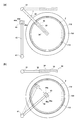
- 2A and 2B are plan views of the plating apparatus shown in FIG.
- FIG. 3 is a view showing a plating solution supply mechanism according to an embodiment of the present invention.
- FIG. 4 is a diagram showing a cleaning liquid supply mechanism and a rinsing liquid supply mechanism according to an embodiment of the present invention.
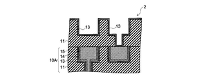
- FIG. 5A is a diagram illustrating a process of preparing a substrate including an insulating layer in which a recess is formed.
- FIG. 5B is a diagram showing a step of forming a barrier film.
- FIG. 5C is a diagram showing a process of cleaning the barrier film.
- FIG. 5D is a diagram showing a step of forming a seed film.
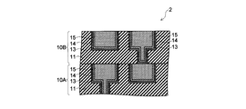
- FIG. 5E is a diagram showing a process of embedding a wiring material in the recess.
- FIG. 5F is a diagram showing a step of removing the wiring material located above the upper surface of the insulating layer.
- FIG. 6A is a diagram illustrating a cleaning liquid discharge process for discharging a cleaning liquid toward the substrate.
- 6B (a) and 6 (b) are views showing a rinsing liquid discharge process for discharging a rinsing liquid toward the substrate.
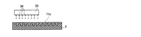
- FIG. 6C is a diagram illustrating a plating solution discharge step of discharging a plating solution toward the substrate.
- FIG. 7 is a side view showing a modification of the plating apparatus.
- FIG. 1 is a side view showing the plating apparatus 20
- FIG. 2 is a plan view showing the plating apparatus 20.
- the plating apparatus 20 holds the substrate 2 inside the casing 101 and rotates the substrate 2, and discharges the plating solution toward the substrate 2 held by the substrate holding mechanism 110.
- a plating solution discharge mechanism 30 and a plating solution supply mechanism 71 connected to the plating solution discharge mechanism 30 and supplying the plating solution to the plating solution discharge mechanism 30 are provided.
- the plating apparatus 20 supplies an inert gas around the substrate 2, a cleaning liquid discharge mechanism 44 that discharges the cleaning liquid toward the substrate 2, a rinse liquid discharge mechanism 45 that discharges a rinse liquid toward the substrate 2, and the substrate 2.
- an inert gas discharge mechanism 46 is connected to the cleaning liquid discharge mechanism 44.
- the rinse liquid discharge mechanism 45 is connected to a cleaning liquid supply mechanism 74 that supplies a rinse liquid to the rinse liquid discharge mechanism 45, and the inert gas discharge mechanism 46 supplies an inert gas to the inert gas discharge mechanism 46.
- An inert gas supply mechanism 75 for supplying is connected.
- the inert gas discharge mechanism 46 is configured to discharge an inert gas toward the substrate 2, thereby replacing the ambient atmosphere of the substrate 2 with the inert gas.
- a gas introduction unit 50 to which a gas such as N 2 gas (nitrogen gas) or clean air is supplied from an FFU (fan filter unit) 51 is provided.
- the gas in the gas introduction part 50 is sent toward the substrate 2 by a down flow through the rectifying plate 52.
- a drain cup 120 having a first opening 121 and a second opening 126 for receiving a liquid such as a plating solution, a cleaning solution or a rinsing solution scattered from the substrate 2, and an opening for drawing a gas.
- An exhaust cup 105 having 106 is arranged.
- the liquid received by the first opening 121 and the second opening 126 of the drainage cup 120 is discharged by the first drainage mechanism 122 and the second drainage mechanism 127.
- the gas drawn into the opening 106 of the exhaust cup 105 is exhausted by the exhaust mechanism 107.
- the drainage cup 120 is connected to the lifting mechanism 164, and the lifting mechanism 164 can move the drainage cup 120 up and down. For this reason, by raising and lowering the drainage cup 120 according to the type of liquid splashed from the substrate 2, the path through which the liquid is discharged can be made different according to the type of liquid.
- the substrate holding mechanism 110 includes a hollow cylindrical rotating shaft member 111 that extends vertically in the casing 101, a turntable 112 attached to the upper end of the rotating shaft member 111, and a turntable 112.
- a wafer chuck 113 that supports the substrate 2 and a rotation mechanism 162 that is connected to the rotation shaft member 111 and that rotates the rotation shaft member 111.
- the rotation mechanism 162 is controlled by the control mechanism 160 and rotates the rotation shaft member 111, whereby the substrate 2 supported by the wafer chuck 113 is rotated.
- the control mechanism 160 can rotate or stop the rotation shaft member 111 and the wafer chuck 113 by controlling the rotation mechanism 162. Further, the control mechanism 160 can control the rotational speed of the rotating shaft member 111 and the wafer chuck 113 to be increased, decreased, or maintained at a constant value.
- the plating solution discharge mechanism 30 has a discharge nozzle 34 that discharges the plating solution toward the substrate 2 and a discharge head 33 provided with the discharge nozzle 34.
- the discharge head 33 accommodates piping for guiding the plating solution supplied from the plating solution supply mechanism 71 to the discharge nozzle 34, piping for circulating a heat medium for keeping the plating solution warm, and the like. .
- the discharge head 33 is configured to be movable in the vertical direction and the horizontal direction.
- the ejection head 33 is attached to the distal end portion of the arm 32, and the arm 32 can be extended in the vertical direction and is fixed to the support shaft 31 that is rotationally driven by the rotation mechanism 165.
- a discharge position at which the discharge head 33 is discharged when discharging the plating solution toward the substrate 2, and the plating solution It is possible to move between the standby positions that are located when the ink is not discharged.
- the ejection head 33 may extend to correspond to the length from the center of the substrate 2 to the peripheral edge of the substrate 2, that is, the radius of the substrate 2.
- the discharge head 33 may be provided with a plurality of discharge nozzles 34 for discharging the plating solution.
- the plating solution can be simultaneously supplied over a wide area of the substrate 2 by positioning the discharge head 33 so that the plurality of discharge nozzles 34 are arranged along the radial direction of the substrate 2 when discharging the plating solution.
- plating solution supply mechanism Next, a plating solution supply mechanism 71 that supplies the plating solution to the plating solution discharge mechanism 30 will be described with reference to FIG.
- the plating solution supply mechanism 71 has a tank 71b for storing the plating solution 71c and a supply pipe 71a for supplying the plating solution 71c in the tank 71b to the plating solution discharge mechanism 30.
- a valve 71d and a pump 71e for adjusting the flow rate of the plating solution 71c are attached to the supply pipe 71a.
- the plating solution supply mechanism 71 may further include a deaeration unit 71f that removes dissolved oxygen in the plating solution 71c.
- the deaeration means 71f may be configured as a gas supply pipe that feeds an inert gas such as nitrogen into the plating solution 71c stored in the tank 71b. As a result, the inert gas can be dissolved in the plating solution 71c, whereby oxygen that has already been dissolved in the plating solution 71c can be discharged to the outside.
- the cleaning liquid discharge mechanism 44 includes a discharge nozzle 44 a that discharges the cleaning liquid toward the substrate 2 and a discharge head 43 provided with the discharge nozzle 44 a.
- the discharge head 43 is configured to be movable in the vertical direction and the horizontal direction.
- the discharge head 43 of the cleaning solution discharge mechanism 44 is attached to the tip of the arm 42, and the arm 42 can be extended in the vertical direction. It is fixed to a support shaft 41 that is rotationally driven by a rotation mechanism 166.
- the ejection head 43 is arranged in the horizontal direction around the support shaft 41 between the position corresponding to the central portion of the substrate 2 and the position corresponding to the peripheral portion of the substrate 2. It is movable.
- the rinse liquid discharge mechanism 45 includes a discharge nozzle 45 a that is provided in the discharge head 43 and discharges the rinse liquid toward the substrate 2.
- the rinse liquid discharge mechanism 45 is configured to share the discharge head 43, the arm 42, the support shaft 41, and the like with the cleaning liquid discharge mechanism 44.
- the inert gas discharge mechanism 46 includes a discharge nozzle 46 a that is provided in the discharge head 43 and discharges the inert gas toward the substrate 2.
- the inert gas discharge mechanism 46 is configured to share the discharge head 43, the arm 42, the support shaft 41, and the like with the cleaning liquid discharge mechanism 44.
- the cleaning liquid supply mechanism 73 has a tank 73b for storing the cleaning liquid 73c, and a supply pipe 73a for supplying the cleaning liquid 73c of the tank 73b to the cleaning liquid discharge mechanism 44.
- a valve 73d and a pump 73e for adjusting the flow rate of the cleaning liquid 73c are attached to the supply pipe 73a.
- the cleaning liquid supply mechanism 73 may further include a deaeration unit 73f that removes dissolved oxygen in the cleaning liquid 73c.
- the deaeration unit 73 f may be configured as a gas supply pipe that sends an inert gas such as nitrogen to the cleaning liquid 73 c stored in the tank 73 b. As a result, the inert gas can be dissolved in the cleaning liquid 73c, whereby oxygen that has already been dissolved in the cleaning liquid 73c can be discharged to the outside.
- the rinsing liquid supply mechanism 74 includes a tank 74b that stores the rinsing liquid 74c, and a supply pipe 74a that supplies the rinsing liquid 74c in the tank 74b to the rinsing liquid discharge mechanism 45. .
- a valve 74d and a pump 74e for adjusting the flow rate of the rinse liquid 74c are attached to the supply pipe 74a.
- the rinse liquid supply mechanism 74 further includes a deaeration unit 74f that removes dissolved oxygen in the rinse liquid 74c. As shown in FIG.
- the deaeration means 74f may be configured as a gas supply pipe that feeds an inert gas such as nitrogen into the rinse liquid 74c stored in the tank 74b.
- an inert gas such as nitrogen
- the inert gas can be dissolved in the rinse liquid 74c, whereby oxygen that has already been dissolved in the rinse liquid 74c can be discharged to the outside.
- the inert gas supply mechanism 75 has a supply pipe 75 a that supplies an inert gas such as nitrogen to the inert gas discharge mechanism 46.
- a valve 75d for adjusting the flow rate of the inert gas is attached to the supply pipe 75a.
- the plating apparatus 20 configured as described above is driven and controlled by the control mechanism 160 in accordance with various programs recorded in the storage medium 161 provided in the control mechanism 160, whereby various processes are performed on the substrate 2.
- the storage medium 161 stores various programs such as various setting data and a plating processing program described later.
- known media such as a computer-readable memory such as ROM and RAM, and a disk-shaped storage medium such as a hard disk, CD-ROM, DVD-ROM, and flexible disk can be used.
- a wiring forming method for forming the second wiring layer on the first wiring layer provided in advance will be described. Specifically, first, a method for forming a recess having an inner surface provided with a barrier film on the first wiring layer will be described. Next, a plating method for forming a seed film on the barrier film by an electroless plating method using the above-described plating apparatus 20 will be described. Thereafter, a plating method for embedding a wiring material in the recess by electroless plating will be described.
- the substrate 2 provided with the first wiring layer 10A formed in a predetermined pattern is prepared.
- the insulating layer 11 is provided on the first wiring layer 10A.
- the material constituting the insulating layer 11 is appropriately selected according to the characteristics required for the semiconductor device. For example, a material having a low dielectric constant such as a SiOCH-based material in which hydrocarbon is doped in SiO 2 is used.
- a recess 12 for embedding a wiring material is formed in the insulating layer 11.
- a metal hard mask layer (not shown) is first formed on the insulating layer 11 in a predetermined pattern, and then the insulating layer 11 is formed using the metal hard mask layer as a mask.
- a method of etching can be used.
- the recess 12 formed in the insulating layer 11 may be a groove configured not to penetrate the insulating layer 11, or may penetrate the insulating layer 11 to form the first wiring layer 10A. It may be a via configured to reach
- copper constituting the wiring 15 of the first wiring layer 10A is between the first wiring layer 10A and the insulating layer 11 of the second wiring layer 10B formed thereon.
- a shield layer for preventing diffusion into the 10B insulating layer 11 may be provided.
- the shield layer is made of, for example, a SiC-based material.
- a barrier film 13 is provided on the inner surface 12 a of the recess 12.
- a metal material which can be plated with a plating solution containing copper and has a barrier property against copper is used.
- a plating solution containing copper and plating is possible means that the barrier film 13 causes a plating reaction to proceed with a plating solution containing copper, thereby forming a film containing copper on the barrier film 13. It is configured to be able to.
- the material constituting the barrier film 13 is a metal nobler than copper, for example, a material containing tantalum.
- the barrier film 13 is composed of a Ta film or a TaN film.
- the barrier film 13 is composed of a Ta film or a TaN film.
- the method of providing the barrier film 13 on the inner surface 12a of the recess 12 is not particularly limited, and a known method is used.
- a physical vapor deposition method such as a sputtering method can be used. In this way, it is possible to prepare the substrate 2 including the insulating layer 11 in which the recess 12 having the inner surface 12a provided with the barrier film 13 including tantalum is formed.
- the plating apparatus 20 is driven and controlled to perform the plating process on the substrate 2 in accordance with the plating process program recorded in the storage medium 161.
- the plating apparatus 20 is driven and controlled to remove the oxide film 13a first and then form the seed film 14 on the barrier film 13 as described below.
- the drain cup 120 is lowered to a predetermined position, and then the substrate 2 is carried into the plating apparatus 20. Next, the loaded substrate 2 is held by the wafer chuck 113 of the substrate holding mechanism 110.
- a cleaning liquid discharge process for discharging the cleaning liquid 73 c from the cleaning liquid discharge mechanism 44 toward the substrate 2 is performed.
- the discharge head 43 of the cleaning liquid discharge mechanism 44 is moved to a position corresponding to the central portion of the substrate 2, and then the cleaning liquid 73 c is discharged from the discharge nozzle 44 a of the cleaning liquid discharge mechanism 44 toward the central portion of the substrate 2.
- the substrate 2 is rotated at a predetermined rotational speed by the substrate holding mechanism 110. 6A, the cleaning liquid 73c supplied to the central portion of the substrate 2 can be caused to flow toward the peripheral portion of the substrate 2 due to the centrifugal force caused by the rotation of the substrate 2. As a result, the cleaning liquid 73 c can be spread over the entire surface of the substrate 2.
- a chemical solution capable of dissolving the oxide film 13a is used, for example, dilute hydrofluoric acid (DHF) is used.
- DHF dilute hydrofluoric acid
- HF hydrofluoric acid
- DIW DIW
- the oxide film 13a formed on the surface of the barrier film 13 can be removed.
- Conditions such as time and temperature for performing this step are appropriately set according to the dimensions of the substrate 2 and the like. For example, a cleaning liquid discharge step of about 5 minutes is performed at room temperature.
- a cleaning liquid 73c such as dilute hydrofluoric acid that has been deoxygenated by the degassing means 73f of the cleaning liquid supply mechanism 73 is supplied to the cleaning liquid discharge mechanism 44 and discharged from the discharge nozzle 44a toward the substrate 2.
- the concentration of oxygen contained in the cleaning liquid 73c can be lowered as compared with the case where a cleaning liquid that has not been subjected to such deoxygenation treatment is used, whereby the surface of the barrier film 13 is oxidized again. Can be suppressed.
- the degree of deoxygenation treatment by the degassing means 73f is not particularly limited.
- the deoxygenation treatment is performed so that the oxygen concentration in the cleaning liquid 73c discharged toward the substrate 2 is 1 ppm or less (preferably 0.5 ppm or less). Is implemented.
- the substrate holding mechanism 110 sets the rotational speed of the substrate 2 to a low rotational speed so that the surface of the substrate 2 is covered with the cleaning liquid 73c discharged from the cleaning liquid discharge mechanism 44, as shown in FIG. 6A.
- the rotation speed of the substrate 2 is set within a range of 1 to 500 rpm, for example, 100 rpm.
- the thickness of the cleaning liquid 73c existing on the substrate 2 can be increased, and this can prevent the surface of the substrate 2 from being exposed to the ambient atmosphere during the cleaning liquid discharge process.
- the surface state of the cleaning liquid 73c existing on the substrate 2 is disturbed, thereby increasing the contact area between the cleaning liquid 73c and the surrounding atmosphere, and as a result, oxygen in the surrounding atmosphere is dissolved in the cleaning liquid 73c. Can be suppressed. By these things, it can suppress that the surface of the barrier film 13 is oxidized again.
- the inert gas discharge mechanism 46 is controlled to discharge the inert gas toward the substrate 2.
- the atmosphere around the substrate 2 can be replaced with an inert gas. That is, the oxygen concentration in the ambient atmosphere of the substrate 2 can be lowered. This can further suppress the surface of the barrier film 13 from being oxidized again.
- FIGS. 6B (a) and 6 (b) a rinsing liquid discharge step of discharging the rinsing liquid 74c from the rinsing liquid discharge mechanism 45 toward the substrate 2 is performed.
- the ejection head 43 is moved to a position corresponding to the center portion of the substrate 2, and then rinsed from the ejection nozzle 45 a of the rinse liquid ejection mechanism 45 toward the center portion of the substrate 2.
- the liquid 74c is discharged.
- a rinsing liquid discharge mechanism is started so that the discharge of the rinsing liquid 74c from the discharge nozzle 45a is started before the cleaning liquid 73c existing on the substrate 2 is shaken off and the surface of the substrate 2 is exposed. 45 is controlled. Further, the substrate 2 is rotated at a predetermined rotational speed by the substrate holding mechanism 110. At this time, preferably, as indicated by an arrow b in FIG. 6B (b), the ejection head 43 provided with the ejection nozzle 45a is moved in the horizontal direction from the center of the substrate 2 toward the peripheral edge of the substrate 2. .
- substrate 2 can be substituted by the rinse liquid 74c rapidly. Further, by moving the discharge head 43 while discharging the rinse liquid 74 c, the rinse liquid 74 c discharged from the discharge nozzle 45 a can reach each concave portion 12 of the substrate 2 directly. Thus, the cleaning liquid 73c can be sufficiently replaced with the rinsing liquid 74c even in the lower portion of the recess 12.
- the rinsing liquid 74c a liquid that can wash away the cleaning liquid 73c without oxidizing the surface of the barrier film 13 again is used.
- DIW or ultrapure water is used.
- the rinse liquid discharge mechanism 45 is supplied with the rinse liquid 74c deoxidized by the degassing means 74f of the rinse liquid supply mechanism 74. For this reason, the concentration of oxygen contained in the rinse liquid 74c can be lowered as compared with the case where a rinse liquid that has not been subjected to such deoxygenation treatment is used, whereby the surface of the barrier film 13 is again formed. Oxidation can be suppressed.
- the degree of deoxygenation treatment by the degassing means 74f is not particularly limited. For example, the deoxygenation is performed so that the oxygen concentration in the rinse liquid 74c discharged toward the substrate 2 is 1 ppm or less (preferably 0.5 ppm or less). Processing is performed.
- the conditions such as the time and temperature for carrying out this step are appropriately set according to the dimensions of the substrate 2 and the like. For example, a rinsing liquid discharging step for about 10 seconds is performed at room temperature. By setting the time short in this way, it is possible to suppress the barrier film 13 from being oxidized again.
- the inert gas discharge mechanism 46 causes the inert gas to flow toward the substrate 2. Controlled to discharge.
- the atmosphere around the substrate 2 can be replaced with an inert gas, which can further prevent the surface of the barrier film 13 from being oxidized again.
- the rotation speed of the substrate 2 may be set to a low rotation speed so that the surface of the substrate 2 is covered with the rinse liquid 74c.
- a plating solution discharge step of discharging the plating solution 71 c from the plating solution discharge mechanism 30 toward the substrate 2 is performed.
- the discharge head 33 is moved so that the plurality of discharge nozzles 34 are aligned along the radial direction of the substrate 2, and then the plating solution 71 c is discharged from each discharge nozzle 34 toward the substrate 2. .
- the plating solution 71c can be supplied simultaneously over a wide area of the substrate 2, whereby the rinsing solution 74c on the substrate 2 can be quickly replaced with the plating solution 71c.
- the plating solution 71c can be sufficiently spread to the lower part of each recess 12.
- the plating solution discharge mechanism is started so that the discharge of the plating solution 71c from the discharge nozzle 34 is started before the rinse liquid 74c existing on the substrate 2 is shaken off and the surface of the substrate 2 is exposed. 30 is controlled.
- a plating solution that can form the seed film 14 on the barrier film 13 by displacement plating such as a plating solution containing copper, is preferably used.
- the seed film 14 can be sufficiently formed up to the lower portion of the recess 12.
- the surface of the barrier film 13 is prevented from being oxidized again in the cleaning liquid discharge process and the rinse liquid discharge process. Therefore, the displacement plating is prevented from being hindered by the oxide film, whereby the seed film 14 can be uniformly formed on the barrier film 13.
- the plating solution 71c deoxidized by the degassing means 71f of the plating solution supply mechanism 71 is supplied to the plating solution discharge mechanism 30 and discharged from the discharge nozzles 34 toward the substrate 2.
- the concentration of oxygen contained in the plating solution 71c can be lowered, whereby the surface of the barrier film 13 is again formed. Oxidation can be suppressed.
- the degree of the deoxygenation treatment by the deaeration means 71f is not particularly limited.
- the deoxygenation is performed so that the oxygen concentration in the plating solution 71c discharged toward the substrate 2 is 1 ppm or less (preferably 0.5 ppm or less). Processing is performed.
- the discharge of the inert gas from the inert gas discharge mechanism 46 toward the substrate 2 may be stopped. Thereby, the gas flow around the substrate 2 can be reduced. Thereby, it is possible to suppress the heat accumulated in the substrate 2 and the plating solution 71c on the substrate 2 from escaping outward. For this reason, it can suppress that the temperature of the plating solution 71c discharged toward the board
- a post-cleaning liquid discharge step for discharging the post-cleaning liquid toward the substrate 2 a rinse liquid discharge step for discharging the rinse liquid toward the substrate 2
- an IPA discharge step for discharging IPA toward the substrate 2 A post-process such as an air discharge process for discharging dry air is performed. Thereafter, the substrate 2 on which the seed film 14 is formed is unloaded from the plating apparatus 20. During these steps, an inert gas, clean air, or the like may be sent toward the substrate 2.
- substrate 2 is carried in in the apparatus for implementing an electroless-plating process.
- the apparatus for example, a plating apparatus similar to the above-described plating apparatus 20 is used.
- a cleaning process and a rinsing process of the substrate 2 are performed, and then a plating solution is supplied into the recess 12 of the substrate 2.
- a plating solution a plating solution containing a conductive material such as copper for constituting the wiring material and a predetermined reducing agent is used.
- the wiring material 15 a can be embedded in the recess 12.
- the wiring material 15 a is provided not only in the recess 12 but also on the upper surface of the insulating layer 11.
- an electroless plating method is used as a plating method. For this reason, compared with the case where an electrolytic plating method is used, the thickness of the wiring material 15a formed in the upper surface of the insulating layer 11 can be made small.
- the wiring material 15a provided on the upper surface of the insulating layer 11 is removed by chemical mechanical polishing.
- the second wiring layer 10B including the wiring 15 provided in the recess 12 can be formed on the first wiring layer 10A.
- the thickness of the wiring material 15a formed on the upper surface of the insulating layer 11 is small. For this reason, compared with the case where an electroplating method is used, the time which a chemical mechanical polishing process requires can be shortened. Further, the amount of the wiring material 15a that is removed and wasted can be reduced.
- the seed film 14 is formed on the barrier film 13 provided on the inner surface of the recess 12 by using an electroless plating method.
- the barrier film 13 includes a plating solution containing copper and a metal that can be plated and has a barrier property against copper, for example, tantalum. Therefore, the seed film 14 is formed on the barrier film 13 by displacement plating. Can be formed. As a result, the seed film 14 can be sufficiently formed below the recess 12 as compared with the case where the seed film 14 is formed on the barrier film 13 by sputtering.
- the deoxidized rinse liquid 74c is discharged toward the barrier film 13 in the rinse liquid discharge step. For this reason, it can suppress that the barrier film 13 oxidizes during the rinse liquid discharge process. Further, the above-described cleaning liquid discharge process, rinse liquid discharge process, and plating liquid discharge process are all performed in the same plating apparatus 20. For this reason, the discharge of the rinsing liquid 74c toward the substrate 2 can be started before the cleaning liquid 73c existing on the substrate 2 is shaken off and the surface of the substrate 2 is exposed. Further, before the rinse liquid 74c existing on the substrate 2 is shaken off and the surface of the substrate 2 is exposed, the discharge of the plating solution 71c toward the substrate 2 can be started. Accordingly, the seed film 14 can be uniformly formed on the barrier film 13 without oxidizing the surface of the barrier film 13 after the oxide film 13a is removed.
- the plating processing device 20 may further include a top plate 21 disposed above the substrate 2.
- the top plate 21 is configured to be movable in the vertical direction.
- the top plate 21 is attached to one end of the support portion 25, and the other end of the support portion 25 is attached to the movable portion 24.
- the movable portion 24 is configured to be moved by the drive mechanism 167 along the support shaft 23 extending in the vertical direction.
- the top plate 21 may be formed with a discharge port 26 for discharging a cleaning solution, a rinsing solution, a plating solution, an inert gas, or the like toward the substrate 2.
- a discharge port 26 for discharging a cleaning solution, a rinsing solution, a plating solution, an inert gas, or the like toward the substrate 2.
- an inert gas supply mechanism 76 that supplies an inert gas to the discharge port 26 is connected to the discharge port 26.
- the following advantages can be obtained by using the top plate 21 in the above-described cleaning liquid discharge process, rinse liquid discharge process, plating liquid discharge process, and the like performed in the plating apparatus 20.
- the top plate 21 may be used to cover the substrate 2 from above during the cleaning liquid discharge process or the rinse liquid discharge process.
- the gas around the substrate 2 can be confined in a narrow space by the top plate 21. Therefore, when the inert gas is discharged toward the substrate 2, the ambient atmosphere around the substrate 2 can be efficiently replaced with the inert gas.
- an inert gas may be discharged toward the substrate 2 using the discharge nozzle 46 a provided in the discharge head 43, or directed toward the substrate 2 using the discharge port 26 provided in the top plate 21.
- An inert gas may be discharged. That is, the discharge port 26 provided in the top plate 21 may function as an inert gas discharge mechanism that discharges the inert gas toward the substrate 2.
- the substrate 2 may be covered from above using the top plate 21 also in the plating solution discharging step. Also in this case, the gas around the substrate 2 can be confined in a narrow space by the top plate 21. For this reason, it can suppress that the heat
- the seed film 14 is formed on the barrier film 13 using the plating apparatus 20, and then a subsequent process such as a post-cleaning process is performed.
- a subsequent process such as a post-cleaning process
- the example which embeds the wiring material 15a in the recessed part 12 using the apparatus of this was shown.
- the present invention is not limited to this, and after the seed film 14 is formed on the barrier film 13, a process of burying the wiring material 15 a in the recess 12 may be performed in the same plating apparatus 20. . That is, the step of forming the seed film 14 and the step of embedding the wiring material 15a in the recess 12 may be performed in the same plating apparatus 20 as a series of electroless plating processes.
- an inert gas such as nitrogen is fed into the liquid as a degassing means for removing oxygen contained in the liquid such as the cleaning liquid 73c, the rinsing liquid 74c, or the plating liquid 71c.
- the specific method for removing oxygen in the liquid is not particularly limited.
- the liquid may be removed by a method of removing oxygen in the liquid by cooling the liquid, a method of removing oxygen in the liquid by reducing the ambient atmosphere of the liquid, or a method in which cooling and decompression are combined.
- the oxygen inside may be removed.
- the configurations of the plating solution discharge mechanism 30, the cleaning solution discharge mechanism 44, the rinse solution discharge mechanism 45, and the inert gas discharge mechanism are not limited to the above examples.
- the plating solution discharge mechanism 30 may include a slit-like discharge port extending along the radial direction of the substrate 2.
- the plating solution discharge mechanism 30 may be configured to discharge the plating solution 71 c toward the center portion of the substrate 2, similarly to the cleaning solution discharge mechanism 44.
- the discharge head 33 of the plating solution discharge mechanism 30 may be configured to be movable in the horizontal direction while discharging the plating solution 71c, similarly to the rinse solution discharge mechanism 45.
- the top plate 21 may be provided with a discharge nozzle or a discharge port for discharging the plating solution toward the substrate 2.
- the rinse liquid discharge mechanism 45 may be configured to discharge the rinse liquid 74 c toward the center of the substrate 2 as in the case of the cleaning liquid discharge mechanism 44.
- a discharge nozzle that discharges the rinsing liquid 74c toward the center of the substrate 2 and a discharge nozzle that discharges the rinsing liquid 74c while moving in the horizontal direction may be used in combination.
- the top plate 21 may be provided with a discharge nozzle or a discharge port for discharging the rinse liquid toward the substrate 2.
- a discharge nozzle or a discharge port that discharges the cleaning liquid toward the substrate 2 may be provided in the top plate 21.
- an inert gas discharge mechanism 46 including a discharge nozzle 46 a provided in the discharge head 43, or a top plate 21 is provided as an inert gas discharge mechanism for supplying an inert gas around the substrate 2.
- an inert gas discharge mechanism including the discharged discharge port 26 is used as an inert gas discharge mechanism that supplies an inert gas around the substrate 2.
- the specific form of the inert gas discharge mechanism is not limited to the form in which the inert gas is directly blown toward the substrate 2, for example, toward the surface of the substrate 2 on which the concave portion is formed.
- the inert gas discharge mechanism can perform the rinsing liquid discharge step on the substrate 2 in a state where at least the concave portion of the surface of the substrate 2 is formed or the entire substrate 2 is in contact with the inert atmosphere. It only has to be configured.
Landscapes
- Chemical & Material Sciences (AREA)
- General Chemical & Material Sciences (AREA)
- Chemical Kinetics & Catalysis (AREA)
- Engineering & Computer Science (AREA)
- Materials Engineering (AREA)
- Mechanical Engineering (AREA)
- Metallurgy (AREA)
- Organic Chemistry (AREA)
- Inorganic Chemistry (AREA)
- Internal Circuitry In Semiconductor Integrated Circuit Devices (AREA)
- Electrodes Of Semiconductors (AREA)
- Chemically Coating (AREA)
Abstract
[課題]バリア膜上に万遍なくシード膜を形成することができるめっき処理装置を提供する。 [解決手段]めっき処理装置20は、基板2に向けて洗浄液を吐出する洗浄液吐出機構44と、基板に向けてリンス液を吐出するリンス液吐出機構45と、基板に向けてめっき液を吐出するめっき液吐出機構30と、を備えている。リンス液吐出機構45には、リンス液吐出機構45にリンス液を供給するリンス液供給機構74が接続されている。このリンス液供給機構74は、脱酸素処理されたリンス液をリンス液吐出機構45に供給することができるよう構成されている。
Description
本発明は、絶縁層に形成された凹部であって、その内面に銅を含むめっき液とめっきが可能でかつ銅に対してバリア性を持つ金属膜が設けられている、凹部に対して、めっき処理を行うめっき処理装置、めっき処理方法および記憶媒体に関する。
一般に、半導体装置を形成するための半導体ウエハや液晶基板などの基板には、回路を形成するための配線が形成されている。配線の形成方法としては、銅などの配線材料を埋め込むためのビアやトレンチなどの凹部を基板の絶縁層に形成し、それらの凹部の中に配線材料を埋め込むダマシン法などが用いられている。
絶縁層の凹部の内面と、凹部に形成される配線との間には一般に、配線材料を構成する原子が絶縁層内に拡散することを防ぐことや、密着性を向上させることを目的としてバリア膜が設けられている。バリア膜としては、Ta膜やTaN膜などのタンタルを含むバリア膜や、Ti膜やTiN膜などチタンを含むバリア膜が知られている。またバリア膜と配線との間には一般に、配線材料の埋め込みを容易にするためのシード膜が設けられている。
例えば特許文献1において、ルテニウムを含むバリア膜をスパッタリングによって凹部の内面に形成し、次に、ルテニウムおよび銅を含むシード膜をスパッタリングによってバリア膜上に形成し、その後、銅をめっき処理によって凹部内に埋め込む方法が提案されている。
近年、配線の更なる微細化への要求のため、配線材料を埋め込むための凹部の径が小さくなっており、このため、凹部のアスペクト比が従来に比べて大きくなっている。また配線の微細化に伴い、配線構造の複雑化も進んでいる。例えば、凹部内に形成される配線において、凹部の深さ方向の位置によって配線の幅が異なるものなどが用いられるようになっている。例えば、上部での幅の方が下部での幅よりも狭い配線などが用いられている。
ところで、シード膜を形成するために一般に用いられているスパッタリング法は、大きな指向性を有する方法である。このため、凹部のアスペクト比が大きい場合や、凹部の構造が複雑になっている場合には、凹部の下部にまで十分にシード膜を形成することが困難である。
本発明は、このような課題を効果的に解決し得るめっき処理装置、めっき処理方法および記憶媒体を提供することを目的とする。
本発明は、絶縁層に形成された凹部であって、その内面に銅を含むめっき液とめっきが可能でかつ銅に対してバリア性を持つ金属膜が設けられている、凹部に対して、めっき処理を行うめっき処理装置において、前記凹部が形成された前記絶縁層を含む基板に向けて洗浄液を吐出する洗浄液吐出機構と、前記基板に向けてリンス液を吐出するリンス液吐出機構と、前記リンス液吐出機構にリンス液を供給するリンス液供給機構と、前記基板に向けてめっき液を吐出するめっき液吐出機構と、を備え、前記リンス液供給機構は、脱酸素処理されたリンス液を前記リンス液吐出機構に供給することができるよう構成されていることを特徴とするめっき処理装置である。
本発明は、絶縁層に形成された凹部であって、その内面に銅を含むめっき液とめっきが可能でかつ銅に対してバリア性を持つ金属膜が設けられている、凹部に対して、めっき処理を行うめっき処理方法において、前記凹部が形成された前記絶縁層を含む基板を準備する工程と、前記基板に向けて洗浄液を吐出する洗浄液吐出工程と、前記洗浄液吐出工程の後、前記基板に向けてリンス液を吐出するリンス液吐出工程と、前記リンス液吐出工程の後、前記基板に向けてめっき液を吐出するめっき液吐出工程と、を備え、前記リンス液吐出工程において、脱酸素処理されたリンス液が前記基板に向けて吐出されることを特徴とするめっき処理方法である。
本発明は、絶縁層に形成された凹部であって、その内面に銅を含むめっき液とめっきが可能でかつ銅に対してバリア性を持つ金属膜が設けられている、凹部に対して、めっき処理を行うめっき処理装置にめっき処理方法を実行させるためのコンピュータプログラムを格納した記憶媒体において、前記めっき処理方法は、前記凹部が形成された前記絶縁層を含む基板を準備する工程と、前記基板に向けて洗浄液を吐出する洗浄液吐出工程と、前記洗浄液吐出工程の後、前記基板に向けてリンス液を吐出するリンス液吐出工程と、前記リンス液吐出工程の後、前記基板に向けてめっき液を吐出するめっき液吐出工程と、を備え、前記リンス液吐出工程において、脱酸素処理されたリンス液が前記基板に向けて吐出される、方法からなっていることを特徴とする記憶媒体である。
本発明によれば、銅を含むめっき液とめっきが可能でかつ銅に対してバリア性を持つ金属膜が設けられている凹部に対してめっき液を吐出することにより、バリア膜上にシード膜または配線を形成する。このため、スパッタリングによってバリア膜上にシード膜を形成する場合に比べて、凹部の下部にまで十分にシード膜または配線を形成することができる。また本発明によれば、銅を含むめっき液とめっきが可能でかつ銅に対してバリア性を持つ金属膜に向けて、脱酸素処理されたリンス液が吐出される。このため、リンス液吐出工程の間にバリア膜が酸化してしまうことを抑制することができ、このことにより、高い品質を有する配線パターンを得ることができる。
以下、図1乃至図6Cを参照して、本発明の一実施の形態について説明する。まず図1および図2を参照して、めっき処理装置20の全体構成について説明する。図1は、めっき処理装置20を示す側面図であり、図2は、めっき処理装置20を示す平面図である。
めっき処理装置
めっき処理装置20は、図1に示すように、ケーシング101の内部で基板2を保持して回転させる基板保持機構110と、基板保持機構110に保持された基板2に向けてめっき液を吐出するめっき液吐出機構30と、めっき液吐出機構30に接続され、めっき液吐出機構30にめっき液を供給するめっき液供給機構71と、を備えている。まためっき処理装置20は、基板2に向けて洗浄液を吐出する洗浄液吐出機構44と、基板2に向けてリンス液を吐出するリンス液吐出機構45と、基板2の周囲に不活性ガスを供給する不活性ガス吐出機構46と、を備えている。このうち洗浄液吐出機構44には、洗浄液吐出機構44に洗浄液を供給する洗浄液供給機構73が接続されている。またリンス液吐出機構45には、リンス液吐出機構45にリンス液を供給する洗浄液供給機構74が接続されており、不活性ガス吐出機構46には、不活性ガス吐出機構46に不活性ガスを供給する不活性ガス供給機構75が接続されている。また本実施の形態において、不活性ガス吐出機構46は、基板2に向けて不活性ガスを吐出し、これによって基板2の周囲雰囲気を不活性ガスへ置換するよう構成されている。
ケーシング101内には、FFU(ファンフィルタユニット)51からN2ガス(窒素ガス)やクリーンエア等のガスが供給される気体導入部50が設けられている。気体導入部50内のガスは、整流板52を介してダウンフローで基板2に向けて送られる。
基板保持機構110の周囲には、基板2から飛散しためっき液、洗浄液やリンス液などの液体を受ける第1開口部121および第2開口部126を有する排液カップ120と、気体を引き込む開口部106を有する排気カップ105と、が配置されている。排液カップ120の第1開口部121および第2開口部126によって受けられた液体は、第1排液機構122および第2排液機構127によって排出される。排気カップ105の開口部106に引き込まれた気体は、排気機構107によって排出される。また、排液カップ120は昇降機構164に連結されており、この昇降機構164は、排液カップ120を上下に移動させることができる。このため、基板2から飛散した液の種類に応じて排液カップ120を上下させることにより、液が排出される経路を液の種類の応じて異ならせることができる。
(基板保持機構)
基板保持機構110は、図2に示すように、ケーシング101内で上下に伸延する中空円筒状の回転軸部材111と、回転軸部材111の上端部に取り付けられたターンテーブル112と、ターンテーブル112の上面外周部に設けられ、基板2を支持するウエハチャック113と、回転軸部材111に連結され、回転軸部材111を回転駆動する回転機構162と、を有している。
基板保持機構110は、図2に示すように、ケーシング101内で上下に伸延する中空円筒状の回転軸部材111と、回転軸部材111の上端部に取り付けられたターンテーブル112と、ターンテーブル112の上面外周部に設けられ、基板2を支持するウエハチャック113と、回転軸部材111に連結され、回転軸部材111を回転駆動する回転機構162と、を有している。
このうち回転機構162は、制御機構160により制御され、回転軸部材111を回転駆動させ、これによって、ウエハチャック113により支持されている基板2が回転される。この場合、制御機構160は、回転機構162を制御することにより、回転軸部材111およびウエハチャック113を回転させ、あるいは停止させることができる。また、制御機構160は、回転軸部材111およびウエハチャック113の回転数を上昇させ、下降させ、あるいは一定値に維持させるように制御することが可能である。
(めっき液吐出機構)
次にめっき液吐出機構30について説明する。めっき液吐出機構30は、基板2に向けてめっき液を吐出する吐出ノズル34と、吐出ノズル34が設けられた吐出ヘッド33と、を有している。吐出ヘッド33内には、めっき液供給機構71から供給されためっき液を吐出ノズル34に導くための配管や、めっき液を保温するための熱媒を循環させるための配管などが収納されている。
次にめっき液吐出機構30について説明する。めっき液吐出機構30は、基板2に向けてめっき液を吐出する吐出ノズル34と、吐出ノズル34が設けられた吐出ヘッド33と、を有している。吐出ヘッド33内には、めっき液供給機構71から供給されためっき液を吐出ノズル34に導くための配管や、めっき液を保温するための熱媒を循環させるための配管などが収納されている。
吐出ヘッド33は、上下方向および水平方向に移動可能となるよう構成されている。例えば吐出ヘッド33は、アーム32の先端部に取り付けられており、このアーム32は、上下方向に延伸可能であるとともに回転機構165により回転駆動される支持軸31に固定されている。このような駆動機構165および支持軸31を用いることにより、図2(a)に示すように、吐出ヘッド33を、基板2に向けてめっき液を吐出する際に位置する吐出位置と、めっき液を吐出しない際に位置する待機位置との間で移動させることができる。
吐出ヘッド33は、図1に示すように、基板2の中心部から基板2の周縁部までの長さ、すなわち基板2の半径の長さに対応するよう延びていてもよい。この場合、吐出ヘッド33には、めっき液を吐出する吐出ノズル34が複数設けられていてもよい。この場合、めっき液を吐出する際に複数の吐出ノズル34が基板2の半径方向に沿って並ぶよう吐出ヘッド33を位置づけることにより、基板2の広域にわたって同時にめっき液を供給することができる。
(めっき液供給機構)
次にめっき液吐出機構30にめっき液を供給するめっき液供給機構71について、図3を参照して説明する。
次にめっき液吐出機構30にめっき液を供給するめっき液供給機構71について、図3を参照して説明する。
図3に示すように、めっき液供給機構71は、めっき液71cを貯留するタンク71bと、タンク71bのめっき液71cをめっき液吐出機構30へ供給する供給管71aと、を有している。供給管71aには、めっき液71cの流量を調整するためのバルブ71dおよびポンプ71eが取り付けられている。まためっき液供給機構71は、めっき液71c中の溶存酸素を除去する脱気手段71fをさらに有していてもよい。脱気手段71fは、図3に示すように、タンク71bに貯留されているめっき液71cに窒素などの不活性ガスを送り込むガス供給管として構成されていてもよい。これによって、不活性ガスをめっき液71c中に溶解させることができ、このことにより、めっき液71c中に既に溶存していた酸素を外部に排出することができる。
(洗浄液吐出機構)
次に洗浄液吐出機構44について説明する。洗浄液吐出機構44は、基板2に向けて洗浄液を吐出する吐出ノズル44aと、吐出ノズル44aが設けられた吐出ヘッド43と、を有している。吐出ヘッド43は、上下方向および水平方向に移動可能となるよう構成されている。例えばめっき液吐出機構30の吐出ヘッド33の場合と同様に、洗浄液吐出機構44の吐出ヘッド43は、アーム42の先端部に取り付けられており、このアーム42は、上下方向に延伸可能であるとともに回転機構166により回転駆動される支持軸41に固定されている。この場合、図2(b)に示すように、吐出ヘッド43は、基板2の中心部に対応する位置と基板2の周縁部に対応する位置との間で支持軸41を軸として水平方向に移動可能となっている。
次に洗浄液吐出機構44について説明する。洗浄液吐出機構44は、基板2に向けて洗浄液を吐出する吐出ノズル44aと、吐出ノズル44aが設けられた吐出ヘッド43と、を有している。吐出ヘッド43は、上下方向および水平方向に移動可能となるよう構成されている。例えばめっき液吐出機構30の吐出ヘッド33の場合と同様に、洗浄液吐出機構44の吐出ヘッド43は、アーム42の先端部に取り付けられており、このアーム42は、上下方向に延伸可能であるとともに回転機構166により回転駆動される支持軸41に固定されている。この場合、図2(b)に示すように、吐出ヘッド43は、基板2の中心部に対応する位置と基板2の周縁部に対応する位置との間で支持軸41を軸として水平方向に移動可能となっている。
(リンス液吐出機構)
図1に示すように、リンス液吐出機構45は、吐出ヘッド43に設けられ、基板2に向けてリンス液を吐出する吐出ノズル45aを有している。このように本実施の形態において、リンス液吐出機構45は、洗浄液吐出機構44との間で吐出ヘッド43,アーム42および支持軸41などを共用するよう構成されている。
図1に示すように、リンス液吐出機構45は、吐出ヘッド43に設けられ、基板2に向けてリンス液を吐出する吐出ノズル45aを有している。このように本実施の形態において、リンス液吐出機構45は、洗浄液吐出機構44との間で吐出ヘッド43,アーム42および支持軸41などを共用するよう構成されている。
(不活性ガス吐出機構)
また図1に示すように、不活性ガス吐出機構46は、吐出ヘッド43に設けられ、基板2に向けて不活性ガスを吐出する吐出ノズル46aを有している。リンス液吐出機構45の場合と同様に、不活性ガス吐出機構46は、洗浄液吐出機構44との間で吐出ヘッド43,アーム42および支持軸41などを共用するよう構成されている。
また図1に示すように、不活性ガス吐出機構46は、吐出ヘッド43に設けられ、基板2に向けて不活性ガスを吐出する吐出ノズル46aを有している。リンス液吐出機構45の場合と同様に、不活性ガス吐出機構46は、洗浄液吐出機構44との間で吐出ヘッド43,アーム42および支持軸41などを共用するよう構成されている。
(供給機構)
次に図4を参照して、各吐出機構44,45,46に洗浄液、リンス液および不活性ガスをそれぞれ供給する供給機構73,74,75について説明する。はじめに洗浄液供給機構73について説明する。
次に図4を参照して、各吐出機構44,45,46に洗浄液、リンス液および不活性ガスをそれぞれ供給する供給機構73,74,75について説明する。はじめに洗浄液供給機構73について説明する。
図4に示すように、洗浄液供給機構73は、洗浄液73cを貯留するタンク73bと、タンク73bの洗浄液73cを洗浄液吐出機構44へ供給する供給管73aと、を有している。供給管73aには、洗浄液73cの流量を調整するためのバルブ73dおよびポンプ73eが取り付けられている。また洗浄液供給機構73は、洗浄液73c中の溶存酸素を除去する脱気手段73fをさらに有していてもよい。脱気手段73fは、図4に示すように、タンク73bに貯留されている洗浄液73cに窒素などの不活性ガスを送り込むガス供給管として構成されていてもよい。これによって、不活性ガスを洗浄液73c中に溶解させることができ、このことにより、洗浄液73c中に既に溶存していた酸素を外部に排出することができる。
また図4に示すように、リンス液供給機構74は、リンス液74cを貯留するタンク74bと、タンク74bのリンス液74cをリンス液吐出機構45へ供給する供給管74aと、を有している。供給管74aには、リンス液74cの流量を調整するためのバルブ74dおよびポンプ74eが取り付けられている。またリンス液供給機構74は、リンス液74c中の溶存酸素を除去する脱気手段74fをさらに有している。脱気手段74fは、図4に示すように、タンク74bに貯留されているリンス液74cに窒素などの不活性ガスを送り込むガス供給管として構成されていてもよい。これによって、不活性ガスをリンス液74c中に溶解させることができ、このことにより、リンス液74c中に既に溶存していた酸素を外部に排出することができる。
また図4に示すように、不活性ガス供給機構75は、窒素などの不活性ガスを不活性ガス吐出機構46へ供給する供給管75aを有している。供給管75aには、不活性ガスの流量を調整するためのバルブ75dが取り付けられている。
以上のように構成されるめっき処理装置20は、制御機構160に設けた記憶媒体161に記録された各種のプログラムに従って制御機構160により駆動制御され、これにより基板2に対する様々な処理が行われる。ここで、記憶媒体161は、各種の設定データや後述するめっき処理プログラム等の各種のプログラムを格納している。記憶媒体161としては、コンピューターで読み取り可能なROMやRAMなどのメモリーや、ハードディスク、CD-ROM、DVD-ROMやフレキシブルディスクなどのディスク状記憶媒体などの公知のものが使用され得る。
配線形成方法
次に、このような構成からなる本実施の形態の作用および効果について説明する。ここでは、予め設けられている第1配線層上に第2配線層を形成する、配線形成方法について説明する。具体的には、まず、内面にバリア膜が設けられた凹部を第1配線層上に形成する方法について説明する。次に、上述のめっき処理装置20を用いた無電解めっき法によって、バリア膜上にシード膜を形成するめっき処理方法について説明する。その後、無電解めっき法によって凹部内に配線材料を埋め込むめっき処理方法について説明する。
次に、このような構成からなる本実施の形態の作用および効果について説明する。ここでは、予め設けられている第1配線層上に第2配線層を形成する、配線形成方法について説明する。具体的には、まず、内面にバリア膜が設けられた凹部を第1配線層上に形成する方法について説明する。次に、上述のめっき処理装置20を用いた無電解めっき法によって、バリア膜上にシード膜を形成するめっき処理方法について説明する。その後、無電解めっき法によって凹部内に配線材料を埋め込むめっき処理方法について説明する。
はじめに、所定のパターンで形成された第1配線層10Aが設けられた基板2を準備する。次に、第1配線層10A上に絶縁層11を設ける。絶縁層11を構成する材料は、半導体装置に求められる特性に応じて適宜選択されるが、例えば、SiO2に炭化水素をドープしたSiOCH系の材料など、低い誘電率を有する材料が用いられる。
その後、図5Aに示すように、配線材料を埋め込むための凹部12を絶縁層11に形成する。凹部12を絶縁層11に形成する方法としては、例えば、はじめに絶縁層11上にメタルハードマスク層(図示せず)を所定のパターンで形成し、その後、メタルハードマスク層をマスクとして絶縁層11をエッチングする方法を用いることができる。なお図5Aに示すように、絶縁層11に形成される凹部12は、絶縁層11を貫通しないよう構成された溝であってもよく、若しくは、絶縁層11を貫通して第1配線層10Aに到達するよう構成されたビアであってもよい。
なお図示はしないが、第1配線層10Aと、その上に形成される第2配線層10Bの絶縁層11との間に、第1配線層10Aの配線15を構成する銅が第2配線層10Bの絶縁層11に拡散することを防ぐためのシールド層が設けられていてもよい。シールド層は、例えばSiC系の材料から構成される。
次に図5Bに示すように、凹部12の内面12aにバリア膜13を設ける。バリア膜13を構成する材料としては、銅を含むめっき液とめっきが可能で、かつ銅に対してバリア性を持つ金属材料が用いられる。ここで「銅を含むめっき液とめっきが可能」とは、バリア膜13が、銅を含むめっき液との間でめっき反応を進行させ、これによってバリア膜13上に銅を含む膜を形成することができるよう構成されていることを意味している。例えばめっき反応が置換めっき反応である場合、バリア膜13を構成する材料としては、銅よりも貴な金属が用いられ、例えばタンタルを含む材料が用いられる。例えばバリア膜13は、Ta膜やTaN膜から構成されている。このようにタンタルを含む材料によってバリア膜13を構成することにより、バリア膜13上にシード膜14を形成する際、銅からなるシード膜14を置換めっきによってバリア膜13上に形成することが可能となる。
凹部12の内面12aにバリア膜13を設ける方法が特に限られることはなく、公知の方法が用いられる。例えばスパッタリング法などの物理蒸着法を用いることができる。このようにして、内面12aにタンタルを含むバリア膜13が設けられている凹部12が形成された絶縁層11を含む基板2を準備することができる。
(シード膜形成工程)
次に、めっき処理装置20を用いて基板2に対して無電解めっき処理を行い、これによってバリア膜13上にシード膜14を形成するめっき処理方法について説明する。めっき処理装置20は、記憶媒体161に記録されためっき処理プログラムに従って、基板2にめっき処理を施すよう駆動制御される。
次に、めっき処理装置20を用いて基板2に対して無電解めっき処理を行い、これによってバリア膜13上にシード膜14を形成するめっき処理方法について説明する。めっき処理装置20は、記憶媒体161に記録されためっき処理プログラムに従って、基板2にめっき処理を施すよう駆動制御される。
ところで、タンタルを含むバリア膜13が大気などの酸素を含む雰囲気に曝されると、図5Bに示すように、バリア膜13の表面が酸化されて酸化膜13aが形成されることが知られている(例えば特許第3715975号公報参照)。従って、めっき処理装置20は、以下に説明するように、はじめに酸化膜13aを除去し、その後にバリア膜13上にシード膜14を形成するよう駆動制御される。
[準備工程]
めっき処理装置20においては、はじめに、排液カップ120を所定位置まで降下させ、その後、めっき処理装置20内に基板2を搬入する。次に、搬入された基板2を基板保持機構110のウエハチャック113によって保持する。
めっき処理装置20においては、はじめに、排液カップ120を所定位置まで降下させ、その後、めっき処理装置20内に基板2を搬入する。次に、搬入された基板2を基板保持機構110のウエハチャック113によって保持する。
[洗浄液吐出工程]
その後、図6Aに示すように、基板2に向けて洗浄液吐出機構44から洗浄液73cを吐出する洗浄液吐出工程を実施する。はじめに、洗浄液吐出機構44の吐出ヘッド43を基板2の中心部に対応する位置まで移動させ、次に、基板2の中心部に向けて洗浄液吐出機構44の吐出ノズル44aから洗浄液73cを吐出させる。また、基板保持機構110によって基板2を所定の回転数で回転させる。これによって、図6Aにおいて矢印aで示すように、基板2の中心部に供給された洗浄液73cを、基板2の回転に起因する遠心力によって基板2の周縁部に向けて流れさせることができる。このことにより、基板2の表面の全域に洗浄液73cを行き渡らせることができる。
その後、図6Aに示すように、基板2に向けて洗浄液吐出機構44から洗浄液73cを吐出する洗浄液吐出工程を実施する。はじめに、洗浄液吐出機構44の吐出ヘッド43を基板2の中心部に対応する位置まで移動させ、次に、基板2の中心部に向けて洗浄液吐出機構44の吐出ノズル44aから洗浄液73cを吐出させる。また、基板保持機構110によって基板2を所定の回転数で回転させる。これによって、図6Aにおいて矢印aで示すように、基板2の中心部に供給された洗浄液73cを、基板2の回転に起因する遠心力によって基板2の周縁部に向けて流れさせることができる。このことにより、基板2の表面の全域に洗浄液73cを行き渡らせることができる。
洗浄液73cとしては、酸化膜13aを溶解させることができる薬液が用いられ、例えば希フッ酸(DHF)が用いられる。例えば、フッ酸(HF)とDIWとの比率が1:9であるDHFを用いることができる。これによって、図5Cに示すように、バリア膜13の表面に形成された酸化膜13aを除去することができる。本工程を実施する時間や温度などの条件は、基板2の寸法などに応じて適宜設定されるが、例えば、室温で約5分間の洗浄液吐出工程が実施される。
好ましくは、洗浄液供給機構73の上述の脱気手段73fによって脱酸素処理された希フッ酸などの洗浄液73cが、洗浄液吐出機構44に供給されて吐出ノズル44aから基板2に向けて吐出される。このため、このような脱酸素処理が施されていない洗浄液が用いられる場合に比べて、洗浄液73cに含まれる酸素の濃度を低くすることができ、これによって、バリア膜13の表面が再び酸化されてしまうことを抑制することができる。脱気手段73fによる脱酸素処理の程度は特には限定されないが、例えば、基板2に向けて吐出される洗浄液73cにおける酸素濃度が1ppm以下(好ましくは0.5ppm以下)となるよう、脱酸素処理が実施される。
また好ましくは、基板保持機構110は、図6Aに示すように、洗浄液吐出機構44から吐出された洗浄液73cによって基板2の表面が覆われるよう、基板2の回転数を低回転数に設定する。例えば基板2の直径が300mmである場合、基板2の回転数を1~500rpmの範囲内、例えば100rpmに設定する。これによって、基板2上に存在している洗浄液73cの厚みを大きくすることができ、このことにより、洗浄液吐出工程の際に基板2の表面が周囲雰囲気に曝されることを防ぐことができる。また、基板2上に存在している洗浄液73cの表面状態が乱れ、これによって洗浄液73cと周囲雰囲気との間の接触面積が増大し、この結果、周囲雰囲気中の酸素が洗浄液73c中に溶解してしまうことを抑制することができる。これらのことにより、バリア膜13の表面が再び酸化されてしまうことを抑制することができる。
また好ましくは、洗浄液吐出機構44が基板2に向けて洗浄液73cを吐出するとき、不活性ガス吐出機構46は、基板2に向けて不活性ガスを吐出するよう制御される。これによって、基板2の周囲雰囲気を不活性ガスによって置換することができる。すなわち、基板2の周囲雰囲気中の酸素濃度を低くすることができる。このことにより、バリア膜13の表面が再び酸化されてしまうことをさらに抑制することができる。
[リンス液吐出工程]
次に、図6B(a)(b)に示すように、基板2に向けてリンス液吐出機構45からリンス液74cを吐出するリンス液吐出工程を実施する。はじめに図6B(a)に示すように、吐出ヘッド43を基板2の中心部に対応する位置まで移動させ、次に、基板2の中心部に向けてリンス液吐出機構45の吐出ノズル45aからリンス液74cを吐出させる。この際、基板2上に存在している洗浄液73cが振り切られて基板2の表面が露出されるよりも前に、吐出ノズル45aからのリンス液74cの吐出が開始されるよう、リンス液吐出機構45が制御される。また、基板保持機構110によって基板2を所定の回転数で回転させる。この際、好ましくは図6B(b)において矢印bで示すように、吐出ノズル45aが設けられた吐出ヘッド43は、基板2の中心部から基板2の周縁部に向けて水平方向に移動される。このため、基板2の回転に起因する遠心力によってのみリンス液74cが基板2の周縁部に到達する場合に比べて、基板2上の洗浄液73cを迅速にリンス液74cに置換することができる。またリンス液74cを吐出しながら吐出ヘッド43を移動させることにより、吐出ノズル45aから吐出されたリンス液74cを基板2の各凹部12に直接到達させることができる。これによって、凹部12の下部においても十分に洗浄液73cをリンス液74cに置換することができる。
次に、図6B(a)(b)に示すように、基板2に向けてリンス液吐出機構45からリンス液74cを吐出するリンス液吐出工程を実施する。はじめに図6B(a)に示すように、吐出ヘッド43を基板2の中心部に対応する位置まで移動させ、次に、基板2の中心部に向けてリンス液吐出機構45の吐出ノズル45aからリンス液74cを吐出させる。この際、基板2上に存在している洗浄液73cが振り切られて基板2の表面が露出されるよりも前に、吐出ノズル45aからのリンス液74cの吐出が開始されるよう、リンス液吐出機構45が制御される。また、基板保持機構110によって基板2を所定の回転数で回転させる。この際、好ましくは図6B(b)において矢印bで示すように、吐出ノズル45aが設けられた吐出ヘッド43は、基板2の中心部から基板2の周縁部に向けて水平方向に移動される。このため、基板2の回転に起因する遠心力によってのみリンス液74cが基板2の周縁部に到達する場合に比べて、基板2上の洗浄液73cを迅速にリンス液74cに置換することができる。またリンス液74cを吐出しながら吐出ヘッド43を移動させることにより、吐出ノズル45aから吐出されたリンス液74cを基板2の各凹部12に直接到達させることができる。これによって、凹部12の下部においても十分に洗浄液73cをリンス液74cに置換することができる。
リンス液74cとしては、バリア膜13の表面を再び酸化させることなく洗浄液73cを洗い流すことができる液が用いられ、例えばDIWや超純水などが用いられる。またリンス液吐出機構45には、リンス液供給機構74の脱気手段74fによって脱酸素処理されたリンス液74cが供給される。このため、このような脱酸素処理が施されていないリンス液が用いられる場合に比べて、リンス液74cに含まれる酸素の濃度を低くすることができ、これによって、バリア膜13の表面が再び酸化されてしまうことを抑制することができる。脱気手段74fによる脱酸素処理の程度は特には限定されないが、例えば、基板2に向けて吐出されるリンス液74cにおける酸素濃度が1ppm以下(好ましくは0.5ppm以下)となるよう、脱酸素処理が実施される。
本工程を実施する時間や温度などの条件は、基板2の寸法などに応じて適宜設定されるが、例えば、室温で約10秒間のリンス液吐出工程が実施される。このように時間を短く設定することにより、バリア膜13が再び酸化されてしまうことを抑制することができる。
好ましくは、上述の洗浄液吐出工程の場合と同様に、リンス液吐出機構45が基板2に向けてリンス液74cを吐出するとき、不活性ガス吐出機構46は、基板2に向けて不活性ガスを吐出するよう制御される。これによって、基板2の周囲雰囲気を不活性ガスによって置換することができ、このことにより、バリア膜13の表面が再び酸化されてしまうことをさらに抑制することができる。
なお本工程においても、上述の洗浄液吐出工程の場合と同様に、基板2の回転数が、リンス液74cによって基板2の表面が覆われる程度の低回転数に設定されてもよい。
[めっき液吐出工程]
次に、図6Cに示すように、基板2に向けてめっき液吐出機構30からめっき液71cを吐出するめっき液吐出工程を実施する。はじめに図6Cに示すように、複数の吐出ノズル34が基板2の半径方向に沿って並ぶよう吐出ヘッド33を移動させ、次に、基板2に向けて各吐出ノズル34からめっき液71cを吐出させる。これによって、基板2の広域にわたって同時にめっき液71cを供給することができ、このことにより、基板2上のリンス液74cを迅速にめっき液71cに置換することができる。また、各凹部12の下部にまで十分にめっき液71cを行き渡らせることができる。この際、基板2上に存在しているリンス液74cが振り切られて基板2の表面が露出するよりも前に、吐出ノズル34からのめっき液71cの吐出が開始されるよう、めっき液吐出機構30が制御される。
次に、図6Cに示すように、基板2に向けてめっき液吐出機構30からめっき液71cを吐出するめっき液吐出工程を実施する。はじめに図6Cに示すように、複数の吐出ノズル34が基板2の半径方向に沿って並ぶよう吐出ヘッド33を移動させ、次に、基板2に向けて各吐出ノズル34からめっき液71cを吐出させる。これによって、基板2の広域にわたって同時にめっき液71cを供給することができ、このことにより、基板2上のリンス液74cを迅速にめっき液71cに置換することができる。また、各凹部12の下部にまで十分にめっき液71cを行き渡らせることができる。この際、基板2上に存在しているリンス液74cが振り切られて基板2の表面が露出するよりも前に、吐出ノズル34からのめっき液71cの吐出が開始されるよう、めっき液吐出機構30が制御される。
めっき液71cとしては、好ましくは、銅を含むめっき液など、置換めっきによってバリア膜13上にシード膜14を形成することができるめっき液が用いられる。これによって、図5Dに示すように、凹部12の下部にまで十分にシード膜14を形成することができる。また上述のように、洗浄液吐出工程やリンス液吐出工程において、バリア膜13の表面が再び酸化されてしまうことが抑制されている。従って、置換めっきが酸化膜によって阻害されることが防がれており、このことにより、バリア膜13上に万遍なくシード膜14を形成することができる。
好ましくは、めっき液供給機構71の上述の脱気手段71fによって脱酸素処理されためっき液71cが、めっき液吐出機構30に供給されて各吐出ノズル34から基板2に向けて吐出される。このため、このような脱酸素処理が施されていないめっき液が用いられる場合に比べて、めっき液71cに含まれる酸素の濃度を低くすることができ、これによって、バリア膜13の表面が再び酸化されてしまうことを抑制することができる。脱気手段71fによる脱酸素処理の程度は特には限定されないが、例えば、基板2に向けて吐出されるめっき液71cにおける酸素濃度が1ppm以下(好ましくは0.5ppm以下)となるよう、脱酸素処理が実施される。
また好ましくは、めっき液吐出機構30が基板2に向けてめっき液71cの吐出を開始してから、基板2上のリンス液74cがめっき液71cに置換されるまでの間、不活性ガス吐出機構46は、基板2に向けて不活性ガスを吐出するよう制御される。これによって、基板2の表面がめっき液71cによって覆われるまでの間にバリア膜13の表面が再び酸化されてしまうことをさらに抑制することができる。
なお、基板2の表面がめっき液71cによって覆われた後は、基板2に向けた不活性ガス吐出機構46からの不活性ガスの吐出を停止してもよい。これによって、基板2の周囲における気体の流れを小さくすることができる。このことにより、基板2や基板2上のめっき液71cに蓄積されている熱が外方に逃げてしまうことを抑制することができる。このため、基板2に向けて吐出されためっき液71cの温度が低下することを抑制することができ、これによって、シード膜14の生成を促進することができる。また、不活性ガスの使用量を削減することができ、このことにより、めっき処理に要するコストを低減することができる。
[後工程]
その後、基板2に向けて後洗浄液を吐出する後洗浄液吐出工程、基板2に向けてリンス液を吐出するリンス液吐出工程、基板2に向けてIPAを吐出するIPA吐出工程、および、基板2に向けてドライエアを吐出するエア吐出工程などの後工程を実施する。その後、シード膜14が形成された基板2をめっき処理装置20から搬出する。これらの工程の際、不活性ガスやクリーンエアなどが基板2に向けて送られていてもよい。
その後、基板2に向けて後洗浄液を吐出する後洗浄液吐出工程、基板2に向けてリンス液を吐出するリンス液吐出工程、基板2に向けてIPAを吐出するIPA吐出工程、および、基板2に向けてドライエアを吐出するエア吐出工程などの後工程を実施する。その後、シード膜14が形成された基板2をめっき処理装置20から搬出する。これらの工程の際、不活性ガスやクリーンエアなどが基板2に向けて送られていてもよい。
(配線材料埋め込み工程)
次に、基板2に対して無電解めっき処理を行い、これによって凹部12内に配線材料を埋め込むめっき処理方法について説明する。
次に、基板2に対して無電解めっき処理を行い、これによって凹部12内に配線材料を埋め込むめっき処理方法について説明する。
[めっき液供給工程]
はじめに、無電解めっき処理を実施するための装置内に基板2を搬入する。装置としては、例えば、上述のめっき処理装置20と同様のめっき処理装置が用いられる。
はじめに、無電解めっき処理を実施するための装置内に基板2を搬入する。装置としては、例えば、上述のめっき処理装置20と同様のめっき処理装置が用いられる。
次に、必要に応じて基板2の洗浄工程やリンス処理工程を行い、その後、基板2の凹部12内にめっき液を供給する。めっき液としては、配線材料を構成するための銅などの導電材料、および、所定の還元剤などを含むめっき液が用いられる。これによって、図5Eに示すように、凹部12内に配線材料15aを埋め込むことができる。
なお本工程においては、凹部12内だけでなく絶縁層11の上面にも配線材料15aが設けられる。ここで本工程においては、めっき処理方法として無電解めっき法が用いられている。このため、電解めっき法が用いられる場合に比べて、絶縁層11の上面に形成される配線材料15aの厚みを小さくすることができる。
[化学機械研磨工程]
その後、化学機械研磨によって、絶縁層11の上面に設けられている配線材料15aを除去する。このようにして、図5Fに示すように、凹部12内に設けられた配線15を備えた第2配線層10Bを第1配線層10A上に形成することができる。
その後、化学機械研磨によって、絶縁層11の上面に設けられている配線材料15aを除去する。このようにして、図5Fに示すように、凹部12内に設けられた配線15を備えた第2配線層10Bを第1配線層10A上に形成することができる。
ところで上述のように、無電解めっき法を用いて凹部12内に配線材料15aを埋め込んでいるため、絶縁層11の上面に設けられる形成される配線材料15aの厚みは小さくなっている。このため、電解めっき法が用いられる場合に比べて、化学機械研磨工程に要する時間を短くすることができる。また、除去されて無駄になる配線材料15aの量を削減することができる。
このように本実施の形態によれば、無電解めっき法を用いて、凹部12の内面に設けられているバリア膜13上にシード膜14を形成する。またバリア膜13は、銅を含むめっき液とめっきが可能でかつ銅に対してバリア性を持つ金属、例えば、タンタルを含んでおり、このため、置換めっきによってバリア膜13上にシード膜14を形成することができる。このことにより、スパッタリングによってバリア膜13上にシード膜14を形成する場合に比べて、凹部12の下部にまで十分にシード膜14を形成することができる。
また本実施の形態によれば、リンス液吐出工程において、脱酸素処理されたリンス液74cがバリア膜13に向けて吐出される。このため、リンス液吐出工程の間にバリア膜13が酸化してしまうことを抑制することができる。また、上述の洗浄液吐出工程、リンス液吐出工程およびめっき液吐出工程がいずれも、同一のめっき処理装置20内において実施される。このため、基板2上に存在する洗浄液73cが振り切られて基板2の表面が露出するよりも前に、基板2に向けたリンス液74cの吐出を開始することができる。また、基板2上に存在するリンス液74cが振り切られて基板2の表面が露出するよりも前に、基板2に向けためっき液71cの吐出を開始することができる。このことにより酸化膜13aが除去された後のバリア膜13の表面を再び酸化させることなく、バリア膜13上に万遍なくシード膜14を形成することができる。
なお、上述した実施の形態に対して様々な変更を加えることが可能である。以下、図面を参照しながら、変形の一例について説明する。以下の説明および以下の説明で用いる図面では、上述した実施の形態と同様に構成され得る部分について、上述の実施の形態における対応する部分に対して用いた符号と同一の符号を用いることとし、重複する説明を省略する。
めっき処理装置の変形例
図7に示すように、めっき処理装置20は、基板2の上方に配置されたトッププレート21をさらに備えていてもよい。トッププレート21は、上下方向に移動可能となるよう構成されている。例えば図7に示すように、トッププレート21は支持部25の一端に取り付けられており、この支持部25の他端は可動部24に取り付けられている。可動部24は、上下方向に延びる支持軸23に沿って、駆動機構167によって動かされるよう構成されている。このような駆動機構167,支持軸23,可動部24および支持部25を用いることにより、状況に応じて基板2とトッププレート21との間の距離を変化させることができる。
図7に示すように、めっき処理装置20は、基板2の上方に配置されたトッププレート21をさらに備えていてもよい。トッププレート21は、上下方向に移動可能となるよう構成されている。例えば図7に示すように、トッププレート21は支持部25の一端に取り付けられており、この支持部25の他端は可動部24に取り付けられている。可動部24は、上下方向に延びる支持軸23に沿って、駆動機構167によって動かされるよう構成されている。このような駆動機構167,支持軸23,可動部24および支持部25を用いることにより、状況に応じて基板2とトッププレート21との間の距離を変化させることができる。
またトッププレート21には、図7に示すように、基板2に向けて洗浄液、リンス液、めっき液または不活性ガスなどを吐出する吐出口26が形成されていてもよい。ここでは、吐出口26が、基板2に向けて不活性ガスを吐出するよう構成されている例について説明する。図7に示すように、吐出口26には、吐出口26に不活性ガスを供給する不活性ガス供給機構76が接続されている。
このようなトッププレート21を用いることにより、基板2の周囲雰囲気がめっき処理装置20の内部に拡散されることを防ぐことができる。このため、基板2の周囲雰囲気に含まれる様々な物質がめっき処理装置20の構成要素に付着し、これによってパーティクルが発生してしまうことを防ぐことができる。
また、めっき処理装置20において実施される上述の洗浄液吐出工程、リンス液吐出工程またはめっき液吐出工程などにおいても、トッププレート21を利用することにより、以下のような利点を得ることができる。
例えば洗浄液吐出工程またはリンス液吐出工程の際、トッププレート21を用いて基板2を上方から覆ってもよい。この場合、トッププレート21によって、基板2の周囲の気体を狭い空間内に閉じ込めることができる。従って、基板2に向けて不活性ガスを吐出する際、基板2の周囲雰囲気を効率的に不活性ガスによって置換することができる。この場合、吐出ヘッド43に設けられた吐出ノズル46aを用いて基板2に向けて不活性ガスを吐出してもよく、若しくは、トッププレート21に設けられた吐出口26を用いて基板2に向けて不活性ガスを吐出してもよい。すなわち、トッププレート21に設けられた吐出口26が、基板2に向けて不活性ガスを吐出する不活性ガス吐出機構として機能してもよい。
まためっき液吐出工程の際にも、トッププレート21を用いて基板2を上方から覆ってもよい。この場合も、トッププレート21によって、基板2の周囲の気体を狭い空間内に閉じ込めることができる。このため、基板2や基板2上のめっき液71cに蓄積されている熱が外方に逃げてしまうことを抑制することができ、これによって、シード膜14の生成を促進することができる。
めっき処理方法の変形例
上述の本実施の形態において、めっき処理装置20を用いてバリア膜13上にシード膜14を形成し、次に、後洗浄工程などの後工程を実施し、その後、別の装置を用いて凹部12内に配線材料15aを埋め込む例を示した。しかしながら、これに限られることはなく、バリア膜13上にシード膜14を形成した後、同一のめっき処理装置20内において続けて、凹部12内に配線材料15aを埋め込む工程を実施してもよい。すなわち、シード膜14を形成する工程と、凹部12内に配線材料15aを埋め込む工程とを、一連の無電解めっき処理工程として同一のめっき処理装置20内で実施してもよい。
上述の本実施の形態において、めっき処理装置20を用いてバリア膜13上にシード膜14を形成し、次に、後洗浄工程などの後工程を実施し、その後、別の装置を用いて凹部12内に配線材料15aを埋め込む例を示した。しかしながら、これに限られることはなく、バリア膜13上にシード膜14を形成した後、同一のめっき処理装置20内において続けて、凹部12内に配線材料15aを埋め込む工程を実施してもよい。すなわち、シード膜14を形成する工程と、凹部12内に配線材料15aを埋め込む工程とを、一連の無電解めっき処理工程として同一のめっき処理装置20内で実施してもよい。
その他の変形例
また本実施の形態において、洗浄液73c、リンス液74cまたはめっき液71cなどの液に含まれる酸素を除去するための脱気手段として、液の中に窒素などの不活性ガスを送り込むことによって液中の酸素を排出する手段が用いられる例を示した。すなわち、いわゆるバブリングによって液中の酸素が除去される例を示した。しかしながら、液中の酸素を除去するための具体的な方法が特に限られることはない。例えば、液を冷却することによって液中の酸素を除去する方法や、液の周囲雰囲気を減圧することによって液中の酸素を除去する方法、または、冷却と減圧とを組み合わせた方法などによって、液中の酸素を除去してもよい。
また本実施の形態において、洗浄液73c、リンス液74cまたはめっき液71cなどの液に含まれる酸素を除去するための脱気手段として、液の中に窒素などの不活性ガスを送り込むことによって液中の酸素を排出する手段が用いられる例を示した。すなわち、いわゆるバブリングによって液中の酸素が除去される例を示した。しかしながら、液中の酸素を除去するための具体的な方法が特に限られることはない。例えば、液を冷却することによって液中の酸素を除去する方法や、液の周囲雰囲気を減圧することによって液中の酸素を除去する方法、または、冷却と減圧とを組み合わせた方法などによって、液中の酸素を除去してもよい。
また、めっき液吐出機構30、洗浄液吐出機構44、リンス液吐出機構45および不活性ガス吐出機構の構成が上述の例に限られることはない。
例えば、めっき液吐出機構30が基板2の半径方向に沿って並べられた複数の吐出ノズル34を含む例を示したが、これに限られることはない。例えば、図示はしないが、めっき液吐出機構30は、基板2の半径方向に沿って延びるスリット状の吐出口を含んでいてもよい。まためっき液吐出機構30は、洗浄液吐出機構44と同様に、基板2の中心部に向けてめっき液71cを吐出するよう構成されていてもよい。まためっき液吐出機構30の吐出ヘッド33は、リンス液吐出機構45と同様に、めっき液71cを吐出しながら水平方向に移動可能となるよう構成されていてもよい。また、基板2に向けてめっき液を吐出する吐出ノズルや吐出口がトッププレート21に設けられていてもよい。
またリンス液吐出機構45の吐出ヘッド43が、リンス液74cを吐出しながら水平方向に移動可能となるよう構成されている例を示したが、これに限られることはない。例えばリンス液吐出機構45は、洗浄液吐出機構44の場合と同様に、基板2の中心部に向けてリンス液74cを吐出するよう構成されていてもよい。また、基板2の中心部に向けてリンス液74cを吐出する吐出ノズルと、水平方向に移動しながらリンス液74cを吐出する吐出ノズルとを組み合わせて用いてもよい。また、基板2に向けてリンス液を吐出する吐出ノズルや吐出口がトッププレート21に設けられていてもよい。同様に、基板2に向けて洗浄液を吐出する吐出ノズルや吐出口がトッププレート21に設けられていてもよい。
また本実施の形態において、基板2の周囲に不活性ガスを供給する不活性ガス吐出機構として、吐出ヘッド43に設けられた吐出ノズル46aを含む不活性ガス吐出機構46や、トッププレート21に設けられた吐出口26を含む不活性ガス吐出機構が用いられる例を示したが、これに限られることはない。例えば、FFU51からのガスをダウンフローで基板2に向けて送る気体導入部50が、基板2の周囲に不活性ガスを供給する不活性ガス吐出機構として機能してもよい。また不活性ガス吐出機構の具体的な形態が、基板2に向けて、例えば基板2の凹部が形成された面に向けて不活性ガスを直接的に吹き付けるような形態に限られることはない。不活性ガス吐出機構は、基板2の面のうち少なくとも凹部が形成された面、または基板2の全体が不活性雰囲気に接触した状態で、基板2に対するリンス液吐出工程を行うことができるように構成されていればよい。
なお、上述した実施の形態に対するいくつかの変形例を説明してきたが、当然に、複数の変形例を適宜組み合わせて適用することも可能である。
2 基板
11 絶縁層
12 凹部
13 バリア膜
20 めっき処理装置
30 めっき液吐出機構
44 洗浄液吐出機構
45 リンス液吐出機構
74 リンス液供給機構
11 絶縁層
12 凹部
13 バリア膜
20 めっき処理装置
30 めっき液吐出機構
44 洗浄液吐出機構
45 リンス液吐出機構
74 リンス液供給機構
Claims (16)
- 絶縁層に形成された凹部であって、その内面に銅を含むめっき液とめっきが可能でかつ銅に対してバリア性を持つ金属膜が設けられている、凹部に対して、めっき処理を行うめっき処理装置において、
前記凹部が形成された前記絶縁層を含む基板に向けて洗浄液を吐出する洗浄液吐出機構と、
前記基板に向けてリンス液を吐出するリンス液吐出機構と、
前記リンス液吐出機構にリンス液を供給するリンス液供給機構と、
前記基板に向けてめっき液を吐出するめっき液吐出機構と、を備え、
前記リンス液供給機構は、脱酸素処理されたリンス液を前記リンス液吐出機構に供給することができるよう構成されていることを特徴とするめっき処理装置。 - 前記基板の周囲に不活性ガスを供給する不活性ガス吐出機構をさらに備え、
前記不活性ガス吐出機構は、少なくとも、前記洗浄液吐出機構による処理と前記めっき液吐出機構による処理との間に前記リンス液吐出機構が前記基板に向けてリンス液を吐出するとき、前記基板の周囲に不活性ガスを供給するよう制御されることを特徴とする請求項1に記載のめっき処理装置。 - 前記基板の上方に配置されたトッププレートをさらに備え、
前記不活性ガス吐出機構は、前記トッププレートに設けられ、前記基板に向けて不活性ガスを吐出する吐出口を有することを特徴とする請求項2に記載のめっき処理装置。 - 前記基板を保持して所定の回転数で回転させる基板保持機構をさらに備え、
前記基板保持機構は、前記洗浄液吐出機構が前記基板に向けて洗浄液を吐出するとき、洗浄液によって前記基板の表面が覆われるよう、前記基板の回転数を設定することを特徴とする請求項1乃至3のいずれか一項に記載のめっき処理装置。 - 前記洗浄液吐出機構に洗浄液を供給する洗浄液供給機構をさらに備え、
前記洗浄液供給機構は、脱酸素処理された洗浄液を前記洗浄液吐出機構に供給することができるよう構成されていることを特徴とする請求項1乃至4のいずれか一項に記載のめっき処理装置。 - 前記リンス液吐出機構は、基板に向けてリンス液を吐出する吐出ノズルが設けられた吐出ヘッドを有し、
前記リンス吐出機構の前記吐出ヘッドは、リンス液を吐出しながら水平方向に移動可能となるよう構成されていることを特徴とする請求項1乃至5のいずれか一項に記載のめっき処理装置。 - 前記めっき液吐出機構は、基板の半径方向に沿って並べられ、基板に向けてめっき液を吐出する複数の吐出ノズルを含む、または、前記基板の半径方向に沿って延びる吐出口を含むことを特徴とする請求項1乃至6のいずれか一項に記載のめっき処理装置。
- 絶縁層に形成された凹部であって、その内面に銅を含むめっき液とめっきが可能でかつ銅に対してバリア性を持つ金属膜が設けられている、凹部に対して、めっき処理を行うめっき処理方法において、
前記凹部が形成された前記絶縁層を含む基板を準備する工程と、
前記基板に向けて洗浄液を吐出する洗浄液吐出工程と、
前記洗浄液吐出工程の後、前記基板に向けてリンス液を吐出するリンス液吐出工程と、
前記リンス液吐出工程の後、前記基板に向けてめっき液を吐出するめっき液吐出工程と、を備え、
前記リンス液吐出工程において、脱酸素処理されたリンス液が前記基板に向けて吐出されることを特徴とするめっき処理方法。 - 前記リンス液吐出工程の際、前記基板の周囲に不活性ガスが供給されることを特徴とする請求項8に記載のめっき処理方法。
- 前記リンス液吐出工程の際、前記基板の上方に配置されたトッププレートに設けられた吐出口から前記基板に向けて不活性ガスが吐出されることを特徴とする請求項9に記載のめっき処理方法。
- 前記リンス液吐出工程の際、前記基板の周囲雰囲気が不活性ガスであることを特徴とする請求項8に記載のめっき処理方法。
- 前記洗浄液吐出工程の際、洗浄液によって前記基板の表面が覆われるよう、前記基板が回転されることを特徴とする請求項8乃至11のいずれか一項に記載のめっき処理方法。
- 前記洗浄液吐出工程において、脱酸素処理された洗浄液が前記基板に向けて吐出されることを特徴とする請求項8乃至12のいずれか一項に記載のめっき処理方法。
- 前記リンス液吐出工程において、水平方向に移動する吐出ヘッドの吐出口から前記基板に向けてリンス液が吐出されることを特徴とする請求項8乃至13のいずれか一項に記載のめっき処理方法。
- 前記めっき液吐出工程において、基板の半径方向に沿って並べられ、基板に向けてめっき液を吐出する複数の吐出ノズルから、または、前記基板の半径方向に沿って延びる吐出口から前記基板に向けてめっき液が吐出されることを特徴とする請求項8乃至14のいずれか一項に記載のめっき処理方法。
- 絶縁層に形成された凹部であって、その内面に銅を含むめっき液とめっきが可能でかつ銅に対してバリア性を持つ金属膜が設けられている、凹部に対して、めっき処理を行うめっき処理装置にめっき処理方法を実行させるためのコンピュータプログラムを格納した記憶媒体において、
前記めっき処理方法は、
前記凹部が形成された前記絶縁層を含む基板を準備する工程と、
前記基板に向けて洗浄液を吐出する洗浄液吐出工程と、
前記洗浄液吐出工程の後、前記基板に向けてリンス液を吐出するリンス液吐出工程と、
前記リンス液吐出工程の後、前記基板に向けてめっき液を吐出するめっき液吐出工程と、を備え、
前記リンス液吐出工程において、脱酸素処理されたリンス液が前記基板に向けて吐出される、方法からなっていることを特徴とする記憶媒体。
Applications Claiming Priority (2)
| Application Number | Priority Date | Filing Date | Title |
|---|---|---|---|
| JP2012084828A JP2013213263A (ja) | 2012-04-03 | 2012-04-03 | めっき処理装置、めっき処理方法および記憶媒体 |
| JP2012-084828 | 2012-04-03 |
Publications (1)
| Publication Number | Publication Date |
|---|---|
| WO2013150828A1 true WO2013150828A1 (ja) | 2013-10-10 |
Family
ID=49300328
Family Applications (1)
| Application Number | Title | Priority Date | Filing Date |
|---|---|---|---|
| PCT/JP2013/054503 Ceased WO2013150828A1 (ja) | 2012-04-03 | 2013-02-22 | めっき処理装置、めっき処理方法および記憶媒体 |
Country Status (3)
| Country | Link |
|---|---|
| JP (1) | JP2013213263A (ja) |
| TW (1) | TWI525227B (ja) |
| WO (1) | WO2013150828A1 (ja) |
Families Citing this family (3)
| Publication number | Priority date | Publication date | Assignee | Title |
|---|---|---|---|---|
| JP6027523B2 (ja) | 2013-12-05 | 2016-11-16 | 東京エレクトロン株式会社 | 基板処理装置及び基板処理方法並びに基板処理プログラムを記録した記録媒体 |
| JP7267015B2 (ja) * | 2019-01-09 | 2023-05-01 | 東京エレクトロン株式会社 | 基板処理方法および基板処理装置 |
| EP4715086A1 (en) * | 2024-09-23 | 2026-03-25 | Atotech Deutschland GmbH & Co. KG | Method and apparatus for non-immersive plating of a surface of a workpiece |
Citations (3)
| Publication number | Priority date | Publication date | Assignee | Title |
|---|---|---|---|---|
| JP2003264159A (ja) * | 2002-03-11 | 2003-09-19 | Ebara Corp | 触媒処理方法及び触媒処理液 |
| JP2005072044A (ja) * | 2003-08-26 | 2005-03-17 | Ebara Corp | 配線形成装置 |
| JP2010067837A (ja) * | 2008-09-11 | 2010-03-25 | Tokyo Electron Ltd | キャップメタル形成方法 |
Family Cites Families (2)
| Publication number | Priority date | Publication date | Assignee | Title |
|---|---|---|---|---|
| JP2004115885A (ja) * | 2002-09-27 | 2004-04-15 | Tokyo Electron Ltd | 無電解メッキ方法 |
| US20080226826A1 (en) * | 2006-06-26 | 2008-09-18 | Tokyo Electon Limited | Substrate Processing Method and Substrate Processing Apparatus |
-
2012
- 2012-04-03 JP JP2012084828A patent/JP2013213263A/ja active Pending
-
2013
- 2013-02-22 WO PCT/JP2013/054503 patent/WO2013150828A1/ja not_active Ceased
- 2013-02-25 TW TW102106601A patent/TWI525227B/zh active
Patent Citations (3)
| Publication number | Priority date | Publication date | Assignee | Title |
|---|---|---|---|---|
| JP2003264159A (ja) * | 2002-03-11 | 2003-09-19 | Ebara Corp | 触媒処理方法及び触媒処理液 |
| JP2005072044A (ja) * | 2003-08-26 | 2005-03-17 | Ebara Corp | 配線形成装置 |
| JP2010067837A (ja) * | 2008-09-11 | 2010-03-25 | Tokyo Electron Ltd | キャップメタル形成方法 |
Also Published As
| Publication number | Publication date |
|---|---|
| TW201348527A (zh) | 2013-12-01 |
| TWI525227B (zh) | 2016-03-11 |
| JP2013213263A (ja) | 2013-10-17 |
Similar Documents
| Publication | Publication Date | Title |
|---|---|---|
| TWI662616B (zh) | 基板處理方法及基板處理裝置 | |
| JP7202230B2 (ja) | 基板処理方法および基板処理装置 | |
| JP5390808B2 (ja) | 基板処理装置および基板処理方法 | |
| JP5381388B2 (ja) | 液処理装置 | |
| US9552994B2 (en) | Plating apparatus, plating method, and storage medium | |
| JPWO2008001697A1 (ja) | 基板処理方法および基板処理装置 | |
| JP2003197591A (ja) | 基板処理装置及び方法 | |
| US20170084480A1 (en) | Substrate processing apparatus, substrate processing method and recording medium | |
| JP6404174B2 (ja) | めっき処理方法、記憶媒体およびめっき処理システム | |
| KR102467696B1 (ko) | 기판 처리 방법 및 기판 처리 장치 | |
| JP7703059B2 (ja) | 基板処理方法および基板処理装置 | |
| JP5917297B2 (ja) | めっき処理方法、めっき処理装置および記憶媒体 | |
| JP7261567B2 (ja) | 基板処理方法および基板処理装置 | |
| US20060003570A1 (en) | Method and apparatus for electroless capping with vapor drying | |
| WO2013150828A1 (ja) | めっき処理装置、めっき処理方法および記憶媒体 | |
| CN113169061B (zh) | 基板处理方法及基板处理装置 | |
| JP2005194613A (ja) | 基板の湿式処理方法及び処理装置 | |
| JP5635422B2 (ja) | 基板乾燥方法、制御プログラム及び基板乾燥装置 | |
| JP4060700B2 (ja) | 基板処理装置及び基板処理方法 | |
| KR102052131B1 (ko) | 도금 처리 장치, 도금 처리 방법 및 기억 매체 | |
| WO2022196077A1 (ja) | 基板処理方法、および、基板処理装置 | |
| JP2005029820A (ja) | めっき方法、半導体装置の製造方法、及びめっき装置 | |
| JP2009238798A (ja) | 基板処理方法および基板処理装置 | |
| WO2024252965A1 (ja) | 基板処理方法、基板処理装置および記憶媒体 | |
| JP2010116601A (ja) | 電解処理装置 |
Legal Events
| Date | Code | Title | Description |
|---|---|---|---|
| 121 | Ep: the epo has been informed by wipo that ep was designated in this application |
Ref document number: 13772620 Country of ref document: EP Kind code of ref document: A1 |
|
| NENP | Non-entry into the national phase |
Ref country code: DE |
|
| 122 | Ep: pct application non-entry in european phase |
Ref document number: 13772620 Country of ref document: EP Kind code of ref document: A1 |