WO2013146259A1 - 光学医療用デバイス及び光学医療用デバイスの制御方法 - Google Patents
光学医療用デバイス及び光学医療用デバイスの制御方法 Download PDFInfo
- Publication number
- WO2013146259A1 WO2013146259A1 PCT/JP2013/056972 JP2013056972W WO2013146259A1 WO 2013146259 A1 WO2013146259 A1 WO 2013146259A1 JP 2013056972 W JP2013056972 W JP 2013056972W WO 2013146259 A1 WO2013146259 A1 WO 2013146259A1
- Authority
- WO
- WIPO (PCT)
- Prior art keywords
- optical
- sheath
- optical element
- medical device
- unit
- Prior art date
- Legal status (The legal status is an assumption and is not a legal conclusion. Google has not performed a legal analysis and makes no representation as to the accuracy of the status listed.)
- Ceased
Links
Images





Classifications
-
- A—HUMAN NECESSITIES
- A61—MEDICAL OR VETERINARY SCIENCE; HYGIENE
- A61B—DIAGNOSIS; SURGERY; IDENTIFICATION
- A61B5/00—Measuring for diagnostic purposes; Identification of persons
- A61B5/0059—Measuring for diagnostic purposes; Identification of persons using light, e.g. diagnosis by transillumination, diascopy, fluorescence
- A61B5/0082—Measuring for diagnostic purposes; Identification of persons using light, e.g. diagnosis by transillumination, diascopy, fluorescence adapted for particular medical purposes
- A61B5/0084—Measuring for diagnostic purposes; Identification of persons using light, e.g. diagnosis by transillumination, diascopy, fluorescence adapted for particular medical purposes for introduction into the body, e.g. by catheters
-
- A—HUMAN NECESSITIES
- A61—MEDICAL OR VETERINARY SCIENCE; HYGIENE
- A61B—DIAGNOSIS; SURGERY; IDENTIFICATION
- A61B5/00—Measuring for diagnostic purposes; Identification of persons
- A61B5/0059—Measuring for diagnostic purposes; Identification of persons using light, e.g. diagnosis by transillumination, diascopy, fluorescence
- A61B5/0062—Arrangements for scanning
- A61B5/0066—Optical coherence imaging
-
- A—HUMAN NECESSITIES
- A61—MEDICAL OR VETERINARY SCIENCE; HYGIENE
- A61B—DIAGNOSIS; SURGERY; IDENTIFICATION
- A61B5/00—Measuring for diagnostic purposes; Identification of persons
- A61B5/68—Arrangements of detecting, measuring or recording means, e.g. sensors, in relation to patient
- A61B5/6846—Arrangements of detecting, measuring or recording means, e.g. sensors, in relation to patient specially adapted to be brought in contact with an internal body part, i.e. invasive
- A61B5/6847—Arrangements of detecting, measuring or recording means, e.g. sensors, in relation to patient specially adapted to be brought in contact with an internal body part, i.e. invasive mounted on an invasive device
- A61B5/6852—Catheters
- A61B5/6855—Catheters with a distal curved tip
Definitions
- the present invention relates to an optical medical device and an optical medical device control method, and more particularly to an optical medical device used by being inserted into a body lumen such as a blood vessel and a vascular vessel and an optical medical device control method.
- diagnostic imaging has been performed by inserting a catheter having an imaging function into a blood vessel such as a coronary artery of the heart or a blood vessel such as a bile duct.
- the diagnostic imaging apparatus examples include an optical coherence tomography (OCT) apparatus.
- OCT optical coherence tomography
- an optical element that irradiates light guided by an optical fiber into a living body lumen is movably disposed in the sheath, and the optical element is moved from the initial position on the distal end side of the sheath to the sheath.
- the optical coherence tomographic image in the living body lumen is continuously acquired by the optical element while being moved backward toward the rear end position located on the base end side (hereinafter sometimes referred to as pullback) (for example, Patent Document 1).
- OFDI optical frequency domain imaging method
- the optical element In the optical coherence tomography apparatus, after acquiring an optical coherence tomographic image by pulling back from the initial position to the rear end position, the optical element is moved forward from the rear end position toward the initial position to return to the initial position (hereinafter referred to as the initial position). , Sometimes referred to as push forward).
- the present invention has been made to solve the above-described problems, and provides an optical medical device and an optical medical device control method in which an optical element can surely return to an initial position in push-forwarding. Objective.
- An optical fiber for guiding light and connected to a distal end side of the drive shaft that is inserted into the sheath, and irradiating light from the optical fiber into the living body lumen
- An optical element for acquiring an optical coherence tomographic image, and an initial position connected to the proximal end side of the drive shaft and the optical element positioned on the distal end side of the sheath, and a rear end positioned on the proximal end side of the sheath
- a drive unit that moves between the position and a position in which the optical element is moved backward from the initial position toward the rear end position by the drive unit,
- a controller that continuously acquires coherence tomographic images, and when the controller moves the optical element forward from the rear end position toward the initial position by the driving unit,
- the method for controlling an optical medical device that achieves the above object obtains an optical coherence tomographic image in the living body lumen by irradiating the living body lumen with light guided by an optical fiber.
- An optical element is movably disposed in a bendable sheath, and the optical element is moved backward from an initial position located on the distal end side of the sheath toward a rear end position located on the proximal end side of the sheath by a driving unit.
- a method for controlling an optical medical device that continuously acquires optical coherence tomographic images in the living body lumen by the optical element, wherein the optical element is moved from the rear end position by the driving unit to the initial position.
- control unit detects the change in the light intensity distribution of the optical coherence tomographic image of the sheath due to the axial deformation of the optical fiber and controls the operation of the driving unit. be able to. For this reason, by appropriately controlling the operation of the drive unit, the load on the drive shaft is reduced, and the optical element can be returned to the initial position.
- the operation of the drive unit is controlled by detecting the change in the light intensity distribution of the optical coherence tomographic image of the sheath due to the axial deformation of the optical fiber. be able to. For this reason, by appropriately controlling the operation of the drive unit, the load on the drive shaft is reduced, and the optical element can be returned to the initial position.
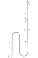
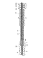
- FIG. 1 is a schematic configuration diagram of an optical medical device according to an embodiment of the present invention. It is a longitudinal direction sectional view showing a joined portion of a sheath body part and a sheath tip member when the imaging core is pushed most into the sheath body part (advance limit position). It is longitudinal direction sectional drawing of a hub. It is the schematic which shows a catheter when an imaging core is pushed most into a sheath main-body part (advance limit position). It is the schematic which shows a catheter when an imaging core is most pulled out from the sheath main-body part (rear end position). It is longitudinal direction sectional drawing with a unit connector and a relay connector.
- FIG. 9A is an image diagram of an optical coherent tomographic image of the sheath main body when the optical fiber is not contracted and deformed.
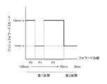
- FIG. 9B is an optical diagram of the sheath main body when the optical fiber is contracted and deformed. It is an image figure of a tomographic image. It is a longitudinal direction sectional view when an imaging core passes the curved position of a sheath main-body part. It is the schematic which shows the speed of push forward of embodiment of this invention. It is a longitudinal direction sectional view of an imaging core when arranged in an initial position.
- proximal end side the hand operating part side of the device
- distal end side the side inserted into the living body lumen
- FIG. 1 is a schematic configuration diagram of an optical medical device according to an embodiment of the present invention.
- FIG. 2 is a longitudinal sectional view showing a joint portion between the sheath body and the sheath tip member.
- an optical medical device 1 includes a bendable sheath 10 that is inserted into a body lumen such as a blood vessel and a vascular vessel, and a bendable sheath 10 that is mechanically inserted into the sheath 10.
- a drive shaft 22 that transmits driving force, an optical fiber 41 that is provided in the drive shaft 22 and guides light, and a distal end side of the drive shaft 22 that is inserted into the sheath 10 are connected to the optical fiber 41. Is connected to the proximal end of the drive shaft 22 and the imaging core 21 is connected to the sheath 10.
- a drive unit 60 that moves between an initial position located on the distal end side of the sheath 10 and a rear end position located on the proximal end side of the sheath 10, and a control unit 71 that controls the operation of the drive unit 60. That.
- the control unit 71 controls the driving unit 60 to continuously move the imaging core 21 from the initial position toward the rear end position (pullback), and continuously generate the optical coherence tomographic image in the living body lumen by the imaging core 21. To get to.
- the control unit 71 uses the imaging core 21 to light the optical coherence tomographic image of the sheath 10.
- the brightness distribution is acquired, and the operation of the drive unit 60 is controlled when a change of the acquired light brightness distribution due to contraction deformation in the axial direction of the optical fiber 41 is detected. Details will be described below.
- the sheath 10, the drive shaft 22, the optical fiber 41, and the imaging core 21 constitute an optical coherence tomography (OCT) catheter (hereinafter sometimes referred to as a catheter) 100.
- OCT optical coherence tomography
- the control unit 71 constitutes a control device 70.
- the catheter 100 is a long and bendable sheath 10 that is inserted into a living body lumen, an image acquisition means 20 for acquiring an optical coherence tomographic image in the living body lumen, and a living body lumen. And an operation unit 30 that is connected to the proximal end side of the sheath 10 and is operated by a user without being inserted into the sheath 10.
- the sheath 10 includes a sheath body 11 and a sheath tip member 12 and is configured by joining the sheath body 11 and the sheath tip member 12.
- the sheath body 11 has a working lumen 11L in which the image acquisition means 20 is incorporated so as to be movable in the axial direction of the sheath 10.
- the sheath tip member 12 has a guide wire lumen 12L through which the guide wire W is inserted.
- the guide wire W is inserted into the living body lumen in advance, and the catheter 100 is guided to the affected part while passing the guide wire W through the sheath tip member 12.
- an X-ray contrast marker 14 is provided in the vicinity of the distal end of the sheath distal end member 12 so that the distal end position of the catheter 100 can be confirmed under fluoroscopy when inserted into a living body lumen.
- the tube wall of the sheath 10 is formed such that the proximal end side of the sheath distal end member 12 transmits an optical signal.
- the catheter 100 according to the present embodiment is a catheter 100 that acquires an image by an optical signal using OCT, and an optical coherence tomographic image can be obtained by transmitting and receiving light through the tube wall of the sheath 10.
- the image acquisition means 20 has an imaging core (optical element) 21 that houses a side-illuminated lens 212 for transmitting and receiving light toward a living body tissue in a housing 211, and the imaging core 21 is attached to the tip. And a drive shaft 22 for transmitting rotational power.
- an imaging core optical element 21 that houses a side-illuminated lens 212 for transmitting and receiving light toward a living body tissue in a housing 211, and the imaging core 21 is attached to the tip.
- a drive shaft 22 for transmitting rotational power.
- the housing 211 is connected to the distal end side of the drive shaft 22, and the side irradiation type lens 212 is fixed to the distal end side of the optical fiber 41.
- the fixing method is not particularly limited, and for example, it can be bonded with an adhesive.
- the drive shaft 22 is flexible and has a characteristic capable of transmitting the mechanical driving force from the driving unit 60 transmitted through the optical connector 51 described later to the imaging core 21.
- the imaging core 21 rotates and the affected part in the living body lumen can be observed 360 degrees.
- the operation unit 30 is connected to the hub 31 on the proximal end side, the unit connector 33 connected to the hub 31 via the inner pipe 32, and the unit connector 33 via the outer pipe 34. And a relay connector 35 for connecting the sheath 10 and the operation unit 30.
- FIG. 3 is a longitudinal sectional view of the hub 31. As shown in FIG. 3, the hub 31 includes a first outer housing 40 and a second outer housing 50.
- the first outer housing 40 has a collar member 42 that defines the rotational axis of the drive shaft 22, and the drive shaft 22 and the optical fiber 41 are provided inside the second outer housing through the collar member 42. Connected to the optical connector 51.
- the second outer housing 50 holds a part of the first outer housing 40 and rotatably holds an optical connector that transmits a mechanical driving force from the driving unit 60 to the drive shaft 22.
- FIG. 4 is a schematic view showing the catheter 100 when the imaging core 21 is pushed most into the sheath body 11.
- FIG. 5 is a schematic view showing the catheter 100 when the imaging core 21 is most pulled out from the sheath body 11.
- the imaging core 21 when the imaging core 21 is pushed in most (hereinafter sometimes referred to as a forward limit position), that is, the imaging core 21 is in the sealing portion S on the distal end side of the sheath body 11.
- a forward limit position when abutting (see FIG. 2), a gap G is generated between the front end side of the hub 31 and the rear end side of the unit connector 33. This is because the imaging core 21 is arranged on the distal end side of the sheath body 11 as much as possible.
- the imaging core 21 is most pulled out from the sheath body 11, that is, when the inner tube 32 is most pulled out (hereinafter sometimes referred to as a rear end position), as shown in FIG.
- the stopper 32A formed at the tip is hooked on the inner wall of the unit connector 33, and the portions other than the vicinity of the hooked tip are exposed.
- the imaging core 21 is pulled back inside the sheath main body 11, and thus is positioned at a position facing the drive unit 60 by the amount of the inner tube 32 pulled out.
- an optical coherence tomographic image in the living body lumen can be continuously acquired, and a three-dimensional image can be acquired.
- FIG. 6 is a longitudinal sectional view of the unit connector 33 and the relay connector 35.
- the unit connector 33 includes a unit connector main body 331, a sealing member 332, and a packing 333.
- An outer tube 34 attached to the relay connector 35 is inserted into the unit connector body 331, and an inner tube 32 extending from the hub 31 is inserted into the outer tube 34.
- the sealing member 332 holds the packing 333 in combination with the unit connector main body 331.
- the inner pipe 32 extending from the hub 31 is formed with a stopper 32A at the tip, even when the hub 31 is most pulled, that is, when the inner pipe 32 is most pulled out from the outer pipe 34, the stopper 32A is The inner pipe 32 is not pulled out from the unit connector 33 by being caught on the inner wall of the connector main body 331.
- the relay connector 35 holds the outer tube 34.
- the proximal end of the sheath body 11 is connected to the inner surface of the relay connector 35, and a path for introducing the drive shaft 22 passing through the outer tube 34 into the sheath body 11 is formed.
- the protective tube 7 is fixed to the inner wall of the outlet member 36 through which the drive shaft 22 of the relay connector 35 passes.
- the protective tube 7 extends toward the inner tube 32 extending from the hub 31. Therefore, when the inner tube 32 is pushed into the outer tube 34, the protective tube 7 is pushed into the inner tube 32 in the direction opposite to the pushing direction. When the inner tube 32 is pushed into or pulled out from the outer tube 34, the protective tube 7 is also pushed into or pulled out from the inner tube 32 in the opposite direction. Therefore, even if the drive shaft 22 comes into contact with the inner tube 32 and friction occurs, and the force that bends to the drive shaft 22 is generated, the force that is deflected by the protective tube 7 can be suppressed, and bending or the like can be prevented.
- the drive unit 60 includes an external drive source M such as a motor and a scanner device 61 including a detection unit 61 ⁇ / b> A that detects a pulse signal of the external drive source M and detects the position of the imaging core 21; An axial movement device 62 that holds the scanner device 61 and moves it in the axial direction by an external drive source M.
- an external drive source M such as a motor
- a scanner device 61 including a detection unit 61 ⁇ / b> A that detects a pulse signal of the external drive source M and detects the position of the imaging core 21;
- An axial movement device 62 that holds the scanner device 61 and moves it in the axial direction by an external drive source M.
- the scanner device 61 By connecting to the optical connector 51, the scanner device 61 transmits and receives light from the imaging core 21 and transmits a driving force for rotating the drive shaft 22 and the optical fiber 41.
- the axial direction moving device 62 includes a scanner gripping portion 621 for gripping and fixing the scanner device 61, and a catheter support portion 622 that supports the sheath 10 so that it does not shift during movement.
- the control device 70 includes a control unit 71 that controls the scanner device 61 and the axial movement device 62, and a display unit 72 that displays an image obtained by the light from the imaging core 21.
- the optical coherence tomographic image is acquired by the optical medical device configured as described above by moving the imaging core 21 backward from the initial position toward the rear end position by the external drive source M in the scanner apparatus 61. This is done by rotating the imaging core 21 by an external drive source M in 61. Therefore, a cross-sectional image of 360 ° in the surrounding tissue body extending in the axial direction in the living body lumen can be obtained in a scanning manner up to an arbitrary position. Note that, at the forward limit position, the imaging core 21 abuts against the sealing portion S and a load is applied to the imaging core 21, so that the initial position is arranged at a position returned by, for example, 1 mm from the forward limit position to the base end side.
- the reflected light from the living body lumen received by the imaging core 21 is transmitted to the control unit 71 via the optical fiber 41 and the optical connector 51, subjected to appropriate processing, and displayed on the display unit 72 as an optical coherence tomographic image.
- the imaging core 21 After acquiring the optical coherence tomographic image, the imaging core 21 is returned from the rear end position to the initial position by the external drive source M in the scanner device 61 (push forward).
- FIG. 7 is a flowchart showing the procedure of the control method of the optical medical device 1.
- step S01 the control unit 71 controls the drive unit 60 to push the imaging core 21 forward from the rear end position toward the forward limit position at a speed of 10 mm / s, while the optical interference of the sheath main body 11 occurs.
- the light intensity distribution of the tomographic image is acquired.
- the drive unit 60 translates the drive shaft 22 along with the rotational motion, thereby acquiring the light intensity distribution in the radial direction of the optical coherence tomographic image as shown in FIG.
- FIG. 8 is an image diagram showing the light luminance distribution of the sheath body 11 and the side irradiation type lens 212.
- the horizontal axis indicates the radial distance
- the vertical axis indicates the light luminance.
- step S02 the rate of change a in the radial direction of the light luminance distribution of the sheath body 11 due to the contraction deformation in the axial direction of the optical fiber 41 is acquired.
- the solid line indicates the light intensity distribution when the optical fiber 41 is not contracted and the broken line indicates the light intensity distribution when the optical fiber 41 is contracted and deformed.
- the left side shows the side-illuminated lens 212
- the center shows the inner wall 11A
- the right side shows the outer wall 11B. From FIG. 8, the optical fiber is contracted and deformed so that the peak position of the light intensity is shifted to the left side, that is, the diameter is reduced.
- the rate of change a is a light intensity peak position indicating the inner wall 11A when the optical fiber 41 is not contracted and deformed in FIG. 8, and a light peak indicating the inner wall 11A when the optical fiber 41 is contracted and deformed.
- the position of intensity is ⁇ , it is obtained by ⁇ / ⁇ .
- the rate of change of the peak position of the light intensity of the inner wall 11A is used as the rate of change a. May be.
- the optical tomographic image as shown in FIG. 9 is displayed by the R ⁇ conversion by the control unit 71 based on the light luminance distribution obtained in FIG. 9A shows an optical coherence tomographic image of the sheath main body 11 and the imaging core 21 when the optical fiber 41 is not contracted and deformed, and FIG. 9B shows a sheath main body when the optical fiber 41 is contracted and deformed. 11 and optical core images of the imaging core 21 are shown.
- the inner ring is an optical coherence tomographic image of the side-illuminated lens 212
- the central ring is an optical coherence tomographic image of the inner wall 11 ⁇ / b> A of the sheath main body 11
- the outer ring is the outer wall of the sheath main body 11.
- 11B shows an optical coherence tomographic image of 11B, and an optical coherence tomographic image of the living body lumen L can be observed further outside.
- 9A and 9B when the optical fiber 41 contracts and deforms in the axial direction, the diameters of the optical coherence tomographic images of the imaging core 21, the inner wall 11A, and the outer wall 11B are reduced.
- the principle that the light intensity distribution changes when the optical fiber 41 contracts and deforms in the axial direction will be described. Since the optical coherence tomographic image is obtained by light interference between the measurement optical path and the reference optical path, when the axial contraction deformation occurs in the optical fiber 41, the distance of the measurement optical path changes, and the light luminance distribution Change. By using this principle to detect the contraction deformation of the optical fiber 41, it is possible to detect a catch on the sheath body 11 of the imaging core 21 or contact with the sealing portion S.
- step S03 it is determined whether or not the position of the imaging core 21 detected by the detection unit 61A exists in a section that includes the rear end position and does not include the initial position (hereinafter may be referred to as a first section).
- the first section is, for example, a case where the entire push-forward distance is 150 mm, and the range is from 150 mm to 10 mm when the forward limit position is the origin.
- a section other than the first section and including the forward limit position and not including the rear end position (hereinafter sometimes referred to as a second section) is in the range of 10 mm to 0 mm.
- step S04 the control unit sets the drive speed of the drive unit 60 to 10 mm / s. At this time, since the first push-forward speed is 10 mm / s, the driving speed of the driving unit 60 is maintained.
- step S05 it is determined whether or not the change rate a acquired in step S02 exceeds a preset threshold value. When it is determined that the change rate a does not exceed the threshold (step S05: NO), the process returns to step S01.
- step S05 the control unit sets the driving speed of the driving unit 60 to 1 mm / Slow down to s.
- the cause of the change in the change rate a in this case is that the imaging core 21 is generated when the imaging core 21 passes through an extremely curved position of the sheath main body 11 to the sheath main body 11. This is contraction deformation in the axial direction of the optical fiber 41 due to the catch. 1 is different from the shape of the sheath 10 in FIG. 1, but this is a simplified description of the sheath 10 in FIG. 1 and is actually arranged along the living body lumen L. As a result, the sheath 10 is bent into various shapes.
- step S06 After the control unit 71 sets the driving speed of the driving unit 60 to 1 mm / s in step S06, the light luminance distribution of the sheath main body 11 is acquired again in step S07, the rate of change a is acquired in step S08, and in step S05. Return to processing. Then, the process of step S06 is repeated until the change rate a does not exceed the threshold value. That is, the imaging core 21 is pushed forward at 1 mm / s. Then, after the imaging core 21 passes through the extremely curved position of the sheath main body 11, if the contraction deformation of the optical fiber 41 is lost, the change rate a does not exceed the threshold (step S05: NO), and again in step S01. Return to processing. When it is determined in step S03 that the imaging core 21 exists in the first section, in step S04, the control unit 71 sets the drive speed of the drive unit 60 to 10 mm / s.
- step S09 the control unit 71 sets the drive speed of the drive unit 60 to 1 mm / s. To do.
- step S10 it is determined whether or not the change rate a acquired in step S02 exceeds a preset threshold value.
- the process returns to step S01.
- the change rate a does not exceed the threshold value, the above process is repeated.
- step S10 When it is determined that the rate of change a exceeds the threshold (step S10: YES), the imaging core 21 is returned to the initial position in step S11 as shown in FIG.
- the cause of the change in the change rate a in this case is contraction deformation in the axial direction of the optical fiber 41 caused by the imaging core 21 coming into contact with the sealing portion S as shown in FIG.
- step S12 After returning the imaging core 21 to the initial position in step S11, the operation of the drive unit 60 is stopped and terminated in step S12.
- the control unit 71 performs light of the sheath main body 11 due to contraction deformation in the axial direction of the optical fiber 41.
- a change in the light luminance distribution of the coherent tomographic image can be detected to control the operation of the drive unit 60. For this reason, by appropriately controlling the operation of the drive unit 60, the load on the drive shaft 22 is reduced, and the imaging core 21 can be returned to the initial position.
- control unit 71 controls the operation of the driving unit 60 when the radial change rate a of the light luminance distribution exceeds a preset threshold value. For this reason, it is possible to automatically detect a change in the light luminance distribution of the sheath body 11 due to the contraction deformation of the optical fiber 41 in the axial direction. Therefore, it is possible to easily detect a change in the light luminance distribution of the sheath body 11 and control the operation of the drive unit 60, leading to an improvement in push forward workability.
- the contraction deformation in the axial direction of the optical fiber 41 is contraction deformation caused by a load when the imaging core 21 passes through the curved position of the sheath main body 11, and the control unit 71 controls the drive unit 60.
- the moving speed of the imaging core 21 is decreased. Therefore, a change in the light intensity distribution of the sheath main body 11 due to the contraction deformation in the axial direction of the optical fiber 41 that occurs when the imaging core 21 passes through the extremely curved position of the sheath main body 11 is detected, and the drive unit
- the movement of the imaging core 21 can be stopped or the moving speed of the imaging core 21 can be reduced by controlling the operation of 60. Therefore, the load on the drive shaft 22 is reduced, the drive shaft 22 is prevented from being damaged, and push forward is maintained.
- the controller 61A further detects whether or not the imaging core 21 is present in the first section, and the controller 71 detects that the imaging core 21 is present in the first section by the detector 61A.
- the operation of the drive unit 60 is controlled when a change in the light luminance distribution is detected. For this reason, when the detection unit 61A determines that the imaging core 21 is present in the first section, the operation of the driving unit 60 is controlled to stop the movement of the imaging core 21 or reduce the moving speed of the imaging core 21. Can do. Therefore, more accurate push forward is possible.
- the contraction deformation in the axial direction of the optical fiber 41 is contraction deformation caused by a load when the imaging core 21 abuts on the sealing portion S.
- the control unit 71 controls the operation of the drive unit 60,
- the imaging core 21 is stopped at an initial position set at a position separated from the forward limit position. For this reason, the change of the light intensity distribution of the sheath body 11 due to the contraction deformation in the axial direction of the optical fiber 41 caused by the imaging core 21 coming into contact with the sealing portion S is detected, and the operation of the drive unit 60 is controlled. Then, the imaging core 21 can be returned to the initial position set at a position separated from the forward limit position and stopped. Therefore, the load on the drive shaft 22 is reduced, and damage to the drive shaft 22 can be prevented.
- the controller 61A further detects whether or not the imaging core 21 is present in the second section, the controller 71 detects that the imaging core 21 is present in the second section by the detector 61A, and When the change of the light luminance distribution is detected, the operation of the drive unit 60 is controlled. For this reason, when the detection unit 61A determines that the imaging core 21 is present in the second section, the operation of the drive unit 60 is controlled to stop the imaging core 21 at the initial position set at a position separated from the forward limit position. be able to. Therefore, more accurate push forward is possible.
- the operation of the driving unit 60 is controlled when the rate of change a exceeds a preset threshold value, but the axial diameter of the optical coherence tomographic image exceeds the preset threshold value. Sometimes, the operation of the drive unit 60 may be controlled.
- the detection unit 61A is used as means for detecting the position of the imaging core 21, but a position sensor provided at an appropriate place may be used.
- the imaging core 21 is pushed forward at a speed of 1 mm / s, and the other positions P2 are pushed forward at a speed of 10 mm / s. It was done. However, these values can be arbitrarily set as appropriate.
- the driving speed of the driving unit 60 is set to 1 mm / s.
- the movement of the imaging core 21 may be stopped. At this time, it is inserted to a position where there is no resistance while being manually inserted and removed, and is automatically pushed forward again.
- the driving speed of the driving unit 60 when the rate of change a exceeds a preset threshold, the driving speed of the driving unit 60 is decreased, but the driving speed of the driving unit 60 is decreased and repeatedly moved back and forth. You may let them.
- Optical medical device 10 sheath, 11 sheath body, 21 Imaging core (optical element), 22 Drive shaft, 41 optical fiber, 60 drive unit, 61A detector, 71 control unit, 100 catheters, L biological lumen, S sealing part.
Landscapes
- Health & Medical Sciences (AREA)
- Life Sciences & Earth Sciences (AREA)
- Medical Informatics (AREA)
- Biophysics (AREA)
- Pathology (AREA)
- Engineering & Computer Science (AREA)
- Biomedical Technology (AREA)
- Heart & Thoracic Surgery (AREA)
- Physics & Mathematics (AREA)
- Molecular Biology (AREA)
- Surgery (AREA)
- Animal Behavior & Ethology (AREA)
- General Health & Medical Sciences (AREA)
- Public Health (AREA)
- Veterinary Medicine (AREA)
- Nuclear Medicine, Radiotherapy & Molecular Imaging (AREA)
- Radiology & Medical Imaging (AREA)
- Endoscopes (AREA)
- Investigating Or Analysing Materials By Optical Means (AREA)
Description
本発明は、光学医療用デバイス及び光学医療用デバイスの制御方法に関し、特に、血管及び脈管などの生体管腔内に挿入して用いられる光学医療用デバイス及び光学医療用デバイスの制御方法に関する。
従来から、撮像機能を有するカテーテルを心臓の冠状動脈などの血管、胆管などの脈管に挿入して、画像診断が行われている。
画像診断装置としては例えば、光干渉断層撮影(OCT:Optical Coherence Tomography)装置が挙げられる。光干渉断層撮影装置は、光ファイバによって導光された光を生体管腔内に照射する光学素子をシース内に移動自在に配置し、光学素子をシースの先端側に位置する初期位置からシースの基端側に位置する後端位置に向けて後退移動させつつ(以下、プルバックと称する場合がある)、光学素子によって生体管腔内の光干渉断層画像を連続的に取得するものである(例えば特許文献1参照)。さらに、最近では、次世代OCTといわれている光周波数領域画像化法(OFDI:optical frequency domain imaging)を用いる画像診断装置も提案されている。
光干渉断層撮影装置において、初期位置から後端位置にプルバックして光干渉断層画像を取得した後、光学素子を後端位置から初期位置に向けて前進移動させて初期位置に戻している(以下、プッシュフォワードと称する場合がある)。
プッシュフォワードする場合において、例えばシースの生体管腔に沿って極端に湾曲した位置を光学素子が通過するとき、光学素子はシースに引っ掛かり、プッシュフォワードを継続して光学素子を初期位置に戻すことが困難となる。
本発明は、上記課題を解決するためになされたものであり、プッシュフォワードする場合において、光学素子が確実に初期位置に戻り得る光学医療用デバイス及び光学医療用デバイスの制御方法を提供することを目的とする。
上記目的を達成する本発明に係る光学医療用デバイスは、生体管腔内に挿入される湾曲自在なシースと、前記シース内に挿入され、機械的駆動力を伝達するドライブシャフトと、前記ドライブシャフト内に設けられ、光を導光する光ファイバと、前記ドライブシャフトにおける前記シース内に挿入される先端側に連結され、前記光ファイバの光を前記生体管腔内に照射して前記生体管腔内の光干渉断層画像を取得する光学素子と、前記ドライブシャフトの基端側に接続され、前記光学素子を前記シースの先端側に位置する初期位置と前記シースの基端側に位置する後端位置との間で移動させる駆動部と、前記駆動部によって前記光学素子を前記初期位置から前記後端位置に向けて後退移動させつつ、前記光学素子によって前記生体管腔内の光干渉断層画像を連続的に取得する制御部と、を有し、前記制御部は、前記駆動部によって前記光学素子を前記後端位置から前記初期位置に向けて前進移動させて戻す場合に、前記光学素子によって前記シースの光干渉断層画像の光輝度分布を取得し、取得した前記光輝度分布の前記光ファイバの軸方向の変形による変化を検知したときに前記駆動部の作動を制御する光学医療用デバイスである。
また、上記目的を達成する本発明に係る光学医療用デバイスの制御方法は、光ファイバによって導光された光を生体管腔内に照射して前記生体管腔内の光干渉断層画像を取得する光学素子を湾曲自在なシース内に移動自在に配置し、駆動部によって前記光学素子を前記シースの先端側に位置する初期位置から前記シースの基端側に位置する後端位置に向けて後退移動させつつ、前記光学素子によって前記生体管腔内の光干渉断層画像を連続的に取得する光学医療用デバイスを制御する方法であって、前記駆動部によって前記光学素子を前記後端位置から前記初期位置に向けて前進移動させて戻す場合に、前記光学素子によって前記シースの光干渉断層画像の光輝度分布を連続的に取得するステップ(a)と、前記光輝度分布の前記光ファイバの軸方向の変形による変化を検知したときに前記駆動部の作動を制御するステップ(b)と、を有する光学医療用デバイスの制御方法である。
上記のように構成された光学医療用デバイスであれば、制御部は、光ファイバの軸方向の変形によるシースの光干渉断層画像の光輝度分布の変化を検知して駆動部の作動を制御することができる。このため、適切に駆動部の作動を制御することによって、ドライブシャフトへの負荷が軽減され、光学素子を初期位置に戻すことができる。
また上記のように構成された光学医療用デバイスの制御方法であれば、光ファイバの軸方向の変形によるシースの光干渉断層画像の光輝度分布の変化を検知して駆動部の作動を制御することができる。このため、適切に駆動部の作動を制御することによって、ドライブシャフトへの負荷が軽減され、光学素子を初期位置に戻すことができる。
以下、図面を参照して、本発明の実施の形態を説明する。なお、図面の寸法比率は、説明の都合上、誇張されて実際の比率とは異なる場合がある。また、以下の説明において、デバイスの手元操作部側を「基端側」、生体管腔内へ挿通される側を「先端側」と称する。
図1は本発明の実施形態に係る光学医療用デバイスの概略構成図である。図2はシース本体部とシース先端部材との接合部分を示す長手方向断面図である。
図1に示すように本発明の実施形態に係る光学医療用デバイス1は、血管及び脈管などの生体管腔内に挿入される湾曲自在なシース10と、シース10内に挿入され、機械的駆動力を伝達するドライブシャフト22と、ドライブシャフト22内に設けられ、光を導光する光ファイバ41と、ドライブシャフト22におけるシース10内に挿入される先端側に連結され、光ファイバ41の光を生体管腔内に照射して生体管腔内の光干渉断層画像を取得するイメージングコア21(光学素子に相当する)と、ドライブシャフト22の基端側に接続され、イメージングコア21をシース10の先端側に位置する初期位置とシース10の基端側に位置する後端位置との間で移動させる駆動部60と、駆動部60の作動を制御する制御部71と、を有する。制御部71は、駆動部60を制御して、イメージングコア21を初期位置から後端位置に向けて後退移動させつつ(プルバック)、イメージングコア21によって生体管腔内の光干渉断層画像を連続的に取得する。また、制御部71は、駆動部60によってイメージングコア21を後端位置から初期位置に向けて前進移動させて戻す場合(プッシュフォワード)には、イメージングコア21によってシース10の光干渉断層画像の光輝度分布を取得し、取得した光輝度分布の光ファイバ41の軸方向の収縮変形による変化を検知したときに駆動部60の作動を制御する。以下、詳述する。
シース10と、ドライブシャフト22と、光ファイバ41と、イメージングコア21とは、光干渉断層撮影(OCT)カテーテル(以下、カテーテルと称する場合がある)100を構成する。また、制御部71は制御装置70を構成する。
カテーテル100は、長尺状であり、かつ湾曲自在であり生体管腔内に挿入されるシース10と、生体管腔内の光干渉断層画像を取得するための画像取得手段20と、生体管腔内に挿入されずシース10の基端側に接続され使用者が操作するための操作部30と、を有する。
図2に示すように、シース10は、シース本体部11と、シース先端部材12と、を有し、シース本体部11及びシース先端部材12を接合することによって構成される。
シース本体部11は、内部に画像取得手段20がシース10の軸方向に移動可能に内蔵されているワーキングルーメン11Lを有する。
シース先端部材12は、内部にガイドワイヤWが挿通されるためのガイドワイヤルーメン12Lを有する。ガイドワイヤWは予め生体管腔内に挿入され、ガイドワイヤWをシース先端部材12に通しながら、カテーテル100が患部まで導かれる。
また、シース先端部材12の先端近傍にはX線造影マーカ14が設けられており、生体管腔内挿入時にX線透視下においてカテーテル100の先端位置が確認できるようになっている。
シース10の管壁は、シース先端部材12よりも基端側が、光信号を透過するように形成されている。本実施形態に係るカテーテル100は、OCTを利用した光信号により画像を取得するカテーテル100であり、シース10の管壁を介して光を送受信することで、光干渉断層画像を得ることができる。
画像取得手段20は、生体管腔内組織に向けて光を送受信するための側方照射型のレンズ212をハウジング211内に収容するイメージングコア(光学素子)21と、イメージングコア21を先端に取り付けるとともに回転動力を伝達するドライブシャフト22と、を有する。
ハウジング211は、ドライブシャフト22の先端側に連結され、側方照射型のレンズ212は、光ファイバ41の先端側に固定されている。固定方法は特に限定されず、たとえば、接着剤によって接着することができる。
ドライブシャフト22は柔軟で、後述する光コネクタ51を介して伝達される駆動部60からの機械的駆動力をイメージングコア21に伝達可能な特性をもっている。ドライブシャフト22が機械的駆動力を伝達することによって、イメージングコア21が回転し、生体管腔内の患部を360度観察することができる。
操作部30は、図1に示すように、基端側のハブ31と、内管32を介してハブ31と接続されるユニットコネクタ33と、外管34を介してユニットコネクタ33に接続されるとともにシース10及び操作部30を接続する中継コネクタ35と、を有する。
図3は、ハブ31の長手方向断面図である。図3に示すように、ハブ31は、第1の外側ハウジング40と、第2の外側ハウジング50と、を有する。
第1の外側ハウジング40は、ドライブシャフト22の回転軸を規定するカラー部材42を有し、ドライブシャフト22及び光ファイバ41はカラー部材42を通って、第2の外側ハウジングの内部に設けられた光コネクタ51に接続される。
第2の外側ハウジング50は、第1の外側ハウジング40の一部を保持し、駆動部60からの機械的駆動力をドライブシャフト22に伝達する光コネクタを回転可能に保持する。
ハブ31は、ドライブシャフト22及び内管32を保持する。また、図4に示すように、内管32がユニットコネクタ33及び外管34に押し込まれ、図5に示すように、引き出されることによって、ドライブシャフト22が連動してシース本体部11内を軸方向にスライドする。ここで、図4はイメージングコア21をシース本体部11に最も押し込んだときのカテーテル100を示す概略図である。図5はイメージングコア21をシース本体部11から最も引き抜いたときのカテーテル100を示す概略図である。
本発明の実施形態に係るカテーテル100は、イメージングコア21を最も押し込んだとき(以下、前進限位置と称する場合がある)、すなわちイメージングコア21がシース本体部11の先端側の封止部Sに当接するとき(図2参照)には、ハブ31の先端側とユニットコネクタ33の後端側との間には隙間Gが生じている。これは、イメージングコア21をできる限りシース本体部11の先端側に配置させるためである。
また、イメージングコア21をシース本体部11から最も引き抜いたとき、すなわち内管32を最も引き出したとき(以下、後端位置と称する場合がある)には、図5に示すように、内管32は、先端に形成されたストッパ32Aがユニットコネクタ33の内壁に引っかかり、引っかかった先端付近以外が露出する。そして、この状態では、イメージングコア21は、シース本体部11の内部を引き戻されていくので、内管32を引き出した分だけ駆動部60の方に向かった場所に位置する。イメージングコア21が回転しながら移動することによって、生体管腔内の光干渉断層画像を連続的に取得し、3次元画像を取得することができる。
図6は、ユニットコネクタ33及び中継コネクタ35の長手方向断面図である。ユニットコネクタ33は、ユニットコネクタ本体331と、封止部材332と、パッキン333と、を有する。
ユニットコネクタ本体331には、中継コネクタ35に取り付けられた外管34が挿入され、この外管34の内部にはハブ31から伸びた内管32が挿入される。封止部材332は、ユニットコネクタ本体331と組み合わさってパッキン333を保持する。
また、ハブ31から伸びる内管32は、先端にストッパ32Aが形成されているので、ハブ31を最も引っ張ったとき、すなわち、内管32を外管34から最も引き出したときでも、ストッパ32Aがユニットコネクタ本体331の内壁に引っ掛かってユニットコネクタ33から内管32が抜けることはない。
中継コネクタ35は、外管34を保持する。また、中継コネクタ35の内面には、シース本体部11の基端側端部が連結されており、外管34から通り抜けたドライブシャフト22をシース本体部11に導入する経路が形成されている。
中継コネクタ35のドライブシャフト22が通り抜ける出口部材36の内壁には、保護管7が固定されている。この保護管7は、ハブ31から伸びる内管32内に向かって伸びる。従って、外管34に内管32が押し込まれるときには、その押し込みの向きと反対向きに内管32に保護管7が押し込まれていくことになる。外管34に内管32が押し込まれたり引き出されたりする際に、反対方向から保護管7も内管32に相対的に押し込まれたり引き出されたりする。従って、ドライブシャフト22が内管32に接触して摩擦が起こり、ドライブシャフト22に撓む力が発生しても、保護管7によって撓む力を抑制し、折れ曲がりなどを防止することができる。
駆動部60は、図1に示すように、モータ等の外部駆動源M及び外部駆動源Mのパルス信号を検出してイメージングコア21の位置を検出する検出部61Aを内蔵するスキャナ装置61と、スキャナ装置61を把持し外部駆動源Mにより軸方向へ移動させる軸方向移動装置62と、を有する。
スキャナ装置61は、光コネクタ51に接続することによって、イメージングコア21からの光の投受光を行うと同時に、ドライブシャフト22及び光ファイバ41を回転させる駆動力を伝達する。
軸方向移動装置62は、スキャナ装置61を把持固定するスキャナ把持部621と、移動時にシース10がずれないように支えるカテーテル支持部622と、を有する。
制御装置70は、スキャナ装置61及び軸方向移動装置62を制御する制御部71と、イメージングコア21からの光によって得られた画像を表示する表示部72と、を有する。
以上のように構成される光学医療用デバイスによる光干渉断層画像の取得は、スキャナ装置61内の外部駆動源Mによってイメージングコア21を初期位置から後端位置に向けて後退移動させつつ、スキャナ装置61内の外部駆動源Mによってイメージングコア21を回転させることによって行われる。よって、生体管腔内の軸方向にわたる包囲組織体における360°の断面画像を任意の位置まで走査的に得ることができる。なお、前進限位置において、イメージングコア21が封止部Sに当接し、イメージングコア21に負荷がかかるため、初期位置は前進限位置より基端側に例えば1mm戻した位置に配置される。
イメージングコア21において受光した生体管腔からの反射光は、光ファイバ41及び光コネクタ51を介して制御部71に送信され、適切な処理が施され、光干渉断層画像として表示部72に表示される。
光干渉断層画像を取得した後、イメージングコア21はスキャナ装置61内の外部駆動源Mによって後端位置から初期位置に戻される(プッシュフォワード)。
次に、本発明の実施形態に係る光学医療用デバイス1の作用について図7~図12を参照して説明する。
図7は、光学医療用デバイス1の制御方法の手順を示すフローチャートである。
ステップS01では、制御部71が駆動部60を制御して、後端位置から前進限位置に向けて、イメージングコア21を10mm/sの速さでプッシュフォワードさせつつ、シース本体部11の光干渉断層画像の光輝度分布を取得する。このとき、駆動部60はドライブシャフト22を回転運動と共に並進運動させることによって、図8に示すように、光干渉断層画像の径方向の光輝度分布が取得される。図8はシース本体部11、側方照射型のレンズ212の光輝度分布を示すイメージ図である。図8において横軸は径方向の距離を、縦軸は光輝度をそれぞれ示している。
ステップS02では、光ファイバ41の軸方向の収縮変形によるシース本体部11の光輝度分布の径方向の変化率aを取得する。図8において、実線は光ファイバ41が収縮変形していないときの光輝度分布であって、破線は光ファイバ41が収縮変形したときの光輝度分布をそれぞれ示している。それぞれの分布においてピークが3本あるうち、左側が側方照射型のレンズ212を、中央が内壁11Aを、右側が外壁11Bを、それぞれ示している。図8から光ファイバが収縮変形することによって光輝度のピーク位置が左側すなわち径が縮小する側にシフトしている。
変化率aは具体的には、図8における光ファイバ41が収縮変形していないときの内壁11Aを示す光輝度のピーク位置をα、光ファイバ41が収縮変形したときの内壁11Aを示す光ピーク強度の位置をβとしたときに、β/αで求められる。なお、本実施形態では変化率aとして内壁11Aの光輝度のピーク位置の変化率を使用したが、側方照射型のレンズ212または外壁11Bの光干渉断層画像の光輝度分布の変化率を用いてもよい。
また、図8において得られた光輝度分布を元に制御部71にてRθ変換されることで、図9のような光断層画像が表示される。図9(A)は光ファイバ41が収縮変形していないときのシース本体部11及びイメージングコア21の光干渉断層画像を、図9(B)は光ファイバ41が収縮変形したときのシース本体部11及びイメージングコア21の光渉断層画像をそれぞれ示している。
図9において、内側の輪は側方照射型のレンズ212の光干渉断層画像を、中央の輪はシース本体部11の内壁11Aの光干渉断層画像を、外側の輪はシース本体部11の外壁11Bの光干渉断層画像をそれぞれ表しており、さらに外側には生体管腔Lの光干渉断層画像を観察することができる。図9(A)、(B)を比較すると、光ファイバ41が軸方向に収縮変形することによって、イメージングコア21、内壁11A及び外壁11Bの光干渉断層画像の径がそれぞれ小さくなっている。
ここで、光ファイバ41が軸方向に収縮変形したときに、光輝度分布が変化する原理について説明する。光干渉断層画像は、測定光路と参照光路との光の干渉によって得られるものであるため、光ファイバ41に軸方向の収縮変形が生じたとき、測定光路の距離が変化し、光輝度分布が変化する。この原理を用いて、光ファイバ41の収縮変形を検知することで、イメージングコア21のシース本体部11に引っ掛かりや封止部Sへの当接などを検知することができる。
ステップS03では、検出部61Aによって検出されるイメージングコア21の位置が、後端位置を含み初期位置を含まない区間(以下、第1区間と称する場合がある)に存在するか否かを判断する。第1区間は例えば、プッシュフォワード距離全体が150mmである場合であって、前進限位置を原点としたとき、150mm~10mmの範囲である。また、第1区間以外である前進限位置を含み後端位置を含まない区間(以下、第2区間と称する場合がある)は、10mm~0mmの範囲である。
イメージングコア21の位置が第1区間に存在すると判断された場合(ステップS03:YES)、ステップS04において制御部は、駆動部60の駆動速度を10mm/sにする。このとき、最初のプッシュフォワードの速度が10mm/sであるため、駆動部60の駆動速度は維持される。
ステップS05では、ステップS02において取得された変化率aが予め設定した閾値を超えるか否かを判断する。変化率aが閾値を超えないと判断される場合(ステップS05:NO)、ステップS01の処理に戻る。
イメージングコア21が第1区間に存在し、変化率aが閾値を超えない場合は上述の処理を繰り返す。イメージングコア21が第1区間に存在する場合であって、変化率aが閾値を超えると判断されるとき(ステップS05:YES)、ステップS06において制御部は、駆動部60の駆動速度を1mm/sに減速する。この場合における変化率aの変化の要因は、図10に示すように、シース本体部11の極端に湾曲した位置をイメージングコア21が通過するときに発生するイメージングコア21のシース本体部11への引っ掛かりに起因する光ファイバ41の軸方向の収縮変形である。なお、図10のシース10は図1のシース10の形状と異なっているが、これは図1のシース10を簡略して記載しているものであって、実際は生体管腔Lに沿って配置されているので、シース10はさまざまな形状に湾曲している。
ステップS06において制御部71が駆動部60の駆動速度を1mm/sにした後に、ステップS07において再度シース本体部11の光輝度分布を取得し、ステップS08において変化率aを取得し、ステップS05の処理に戻る。そして、変化率aが閾値を超えなくなるまでステップS06の処理が繰り返される。すなわち、イメージングコア21は1mm/sでプッシュフォワードされる。そして、イメージングコア21がシース本体部11の極端に湾曲した位置を通過した後に、光ファイバ41の収縮変形がなくなると、変化率aが閾値を超えなくなり(ステップS05:NO)、再度ステップS01の処理に戻る。そして、ステップS03でイメージングコア21が第1区間に存在すると判断された場合、ステップS04において、制御部71は駆動部60の駆動速度を10mm/sにする。
このように制御することによって第1区間において、図11に示すように、シース本体部11が極端に湾曲した位置P1を通過するときは、イメージングコア21は1mm/sの速度でプッシュフォワードされ、それ以外の位置P2を通過するときは、10mm/sの速度でプッシュフォワードされる。
次に、イメージングコア21が第2区間に存在すると判断される場合(ステップS03:NO)、図11に示すように、ステップS09において、制御部71は駆動部60の駆動速度を1mm/sにする。
ステップS10では、ステップS02において取得された変化率aが予め設定した閾値を超えるか否かを判断する。ステップS02において取得された変化率aが閾値を超えないと判断される場合(ステップS10:NO)、ステップS01の処理に戻る。変化率aが閾値を超えない場合は上述の処理を繰り返す。
そして、変化率aが閾値を超えると判断されるとき(ステップS10:YES)、ステップS11においてイメージングコア21を図12に示すように初期位置に戻す。この場合における変化率aの変化の要因は、図2に示すように、イメージングコア21が封止部Sに当接することに起因する光ファイバ41の軸方向の収縮変形である。
ステップS11においてイメージングコア21を初期位置に戻した後に、ステップS12において駆動部60の作動は停止して終了する。
以上説明したように、本実施形態に係る光学医療用デバイス1及び光学医療用デバイス1の制御方法によれば、制御部71は、光ファイバ41の軸方向の収縮変形によるシース本体部11の光干渉断層画像の光輝度分布の変化を検知して駆動部60の作動を制御することができる。このため、適切に駆動部60の作動を制御することによって、ドライブシャフト22への負荷が軽減され、イメージングコア21を初期位置に戻すことができる。
また、制御部71は、光輝度分布の径方向の変化率aが予め設定した閾値を超えたときに駆動部60の作動を制御する。このため、光ファイバ41の軸方向の収縮変形によるシース本体部11の光輝度分布の変化を自動で検知できる。よって、容易にシース本体部11の光輝度分布の変化を検知して、駆動部60の作動を制御でき、プッシュフォワードの作業性向上につながる。
また、光ファイバ41の軸方向の収縮変形は、イメージングコア21がシース本体部11の湾曲した位置を通過するときの負荷に起因して生じる収縮変形であり、制御部71は、駆動部60の作動を制御して、イメージングコア21の移動速度を低下させる。このため、シース本体部11の極端に湾曲した位置をイメージングコア21が通過するときに生じる光ファイバ41の軸方向の収縮変形によるシース本体部11の光輝度分布の変化を検知して、駆動部60の作動を制御して、イメージングコア21の移動を停止、またはイメージングコア21の移動速度を低下させることができる。よって、ドライブシャフト22への負荷が軽減され、ドライブシャフト22の破損を防止して、プッシュフォワードが維持される。
また、第1区間にイメージングコア21が存在するか否かを検出する検出部61Aをさらに有し、制御部71は、検出部61Aによってイメージングコア21が第1区間に存在することを検出し、かつ、光輝度分布の変化を検知したときに駆動部60の作動を制御する。このため、第1区間にイメージングコア21が存在すると検出部61Aが判断するとき、駆動部60の作動を制御して、イメージングコア21の移動を停止、またはイメージングコア21の移動速度を低下させることができる。よって、より正確なプッシュフォワードが可能となる。
光ファイバ41の軸方向の収縮変形は、イメージングコア21が封止部Sに当接するときの負荷に起因して生じる収縮変形であり、制御部71は、駆動部60の作動を制御して、前進限位置から離隔した位置に設定した初期位置にイメージングコア21を停止させる。このため、イメージングコア21が封止部Sに当接することに起因する光ファイバ41の軸方向の収縮変形によるシース本体部11の光輝度分布の変化を検知して、駆動部60の作動を制御して、前進限位置から離隔した位置に設定した初期位置にイメージングコア21を戻して停止させることができる。よって、ドライブシャフト22への負荷が軽減され、ドライブシャフト22の破損を防止できる。
第2区間にイメージングコア21が存在するか否かを検出する検出部61Aをさらに有し、制御部71は、検出部61Aによってイメージングコア21が第2区間に存在することを検出し、かつ、光輝度分布の変化を検知したときに駆動部60の作動を制御する。このため、第2区間にイメージングコア21が存在すると検出部61Aが判断するとき、駆動部60の作動を制御して、前進限位置から離隔した位置に設定した初期位置にイメージングコア21を停止させることができる。よって、より正確なプッシュフォワードが可能となる。
(改変例)
本発明に係る実施形態では、変化率aが予め設定された閾値を超えたときに駆動部60の作動を制御したが、光干渉断層画像の軸方向の径が予め設定された閾値を超えたときに駆動部60の作動を制御してもよい。
本発明に係る実施形態では、変化率aが予め設定された閾値を超えたときに駆動部60の作動を制御したが、光干渉断層画像の軸方向の径が予め設定された閾値を超えたときに駆動部60の作動を制御してもよい。
また、本発明に係る実施形態では、イメージングコア21の位置を検出する手段として検出部61Aを使用したが、適切な場所に設けられた位置センサーであってもよい。
また、本発明に係る実施形態では、シース本体部11が極端に湾曲した位置P1については、イメージングコア21は1mm/sの速度で、それ以外の位置P2については10mm/sの速度でプッシュフォワードされた。しかしながら、これらの速度は適宜任意の値を設定することができる。
また、本発明に係る実施形態では、シース本体部11が極端に湾曲した位置P1をイメージングコア21が通過する場合、駆動部60の駆動速度を1mm/sにした。しかしながらイメージングコア21の移動を停止させてもよい。このとき、手動にて抜き差ししながら抵抗が無い位置まで挿入して、再度自動にてプッシュフォワードする。
また、本発明に係る実施形態では、変化率aが予め設定した閾値を超えたとき、駆動部60の駆動速度を低下させたが、駆動部60の駆動速度を低速させて、前後に繰り返し移動させてもよい。
さらに、本出願は、2012年3月26日に出願された日本特許出願番号2012-070451号に基づいており、それらの開示内容は、参照され、全体として、組み入れられている。
1 光学医療用デバイス、
10 シース、
11 シース本体部、
21 イメージングコア(光学素子)、
22 ドライブシャフト、
41 光ファイバ、
60 駆動部、
61A 検出部、
71 制御部、
100 カテーテル、
L 生体管腔、
S 封止部。
10 シース、
11 シース本体部、
21 イメージングコア(光学素子)、
22 ドライブシャフト、
41 光ファイバ、
60 駆動部、
61A 検出部、
71 制御部、
100 カテーテル、
L 生体管腔、
S 封止部。
Claims (12)
- 生体管腔内に挿入される湾曲自在なシースと、
前記シース内に挿入され、機械的駆動力を伝達するドライブシャフトと、
前記ドライブシャフト内に設けられ、光を導光する光ファイバと、
前記ドライブシャフトにおける前記シース内に挿入される先端側に連結され、前記光ファイバの光を前記生体管腔内に照射して前記生体管腔内の光干渉断層画像を取得する光学素子と、
前記ドライブシャフトの基端側に接続され、前記光学素子を前記シースの先端側に位置する初期位置と前記シースの基端側に位置する後端位置との間で移動させる駆動部と、
前記駆動部によって前記光学素子を前記初期位置から前記後端位置に向けて後退移動させつつ、前記光学素子によって前記生体管腔内の光干渉断層画像を連続的に取得する制御部と、を有し、
前記制御部は、前記駆動部によって前記光学素子を前記後端位置から前記初期位置に向けて前進移動させて戻す場合に、前記光学素子によって前記シースの光干渉断層画像の光輝度分布を取得し、取得した前記光輝度分布の前記光ファイバの軸方向の変形による変化を検知したときに前記駆動部の作動を制御する光学医療用デバイス。 - 前記制御部は、前記光輝度分布の径方向の変化率が予め設定した閾値を超えたときに前記駆動部の作動を制御する請求項1に記載の光学医療用デバイス。
- 前記光ファイバの軸方向の変形は、前記光学素子が前記シースの湾曲した位置を通過するときの負荷に起因して生じる収縮変形であり、
前記制御部は、前記駆動部の作動を制御して、前記光学素子の移動を停止、または前記光学素子の移動速度を低下させる請求項1または2に記載の光学医療用デバイス。 - 前記後端位置を含み前記初期位置を含まない区間に前記光学素子が存在するか否かを検出する検出部をさらに有し、
前記制御部は、前記検出部によって前記光学素子が前記区間に存在することを検出し、かつ、前記光輝度分布の変化を検知したときに前記駆動部の作動を制御する請求項3に記載の光学医療用デバイス。 - 前記光ファイバの軸方向の変形は、前記光学素子が前記シースの先端側の封止部に当接するときの負荷に起因して生じる収縮変形であり、
前記制御部は、前記駆動部の作動を制御して、前記前進限位置から離隔した位置に設定した前記初期位置に前記光学素子を停止させる請求項1または2に記載の光学医療用デバイス。 - 前記前進限位置を含み前記後端位置を含まない区間に前記光学素子が存在するか否かを検出する検出部をさらに有し、
前記制御部は、前記検出部によって前記光学素子が前記区間に存在することを検出し、かつ、前記光輝度分布の変化を検知したときに前記駆動部の作動を制御する請求項5に記載の光学医療用デバイス。 - 光ファイバによって導光された光を生体管腔内に照射して前記生体管腔内の光干渉断層画像を取得する光学素子を湾曲自在なシース内に移動自在に配置し、駆動部によって前記光学素子を前記シースの先端側に位置する初期位置から前記シースの基端側に位置する後端位置に向けて後退移動させつつ、前記光学素子によって前記生体管腔内の光干渉断層画像を連続的に取得する光学医療用デバイスを制御する方法であって、
前記駆動部によって前記光学素子を前記後端位置から前記初期位置に向けて前進移動させて戻す場合に、前記光学素子によって前記シースの光干渉断層画像の光輝度分布を連続的に取得するステップ(a)と、
前記光輝度分布の前記光ファイバの軸方向の変形による変化を検知したときに前記駆動部の作動を制御するステップ(b)と、を有する光学医療用デバイスの制御方法。 - 前記ステップ(b)において、前記光輝度分布の径方向の変化率が予め設定した閾値を超えたときに前記駆動部の作動を制御する請求項7に記載の光学医療用デバイスの制御方法。
- 前記ステップ(b)において、前記光ファイバの軸方向の変形は前記光学素子が前記シースの湾曲した位置を通過するときの負荷に起因して生じる収縮変形であり、
前記駆動部の作動を制御して、前記光学素子の移動を停止、または前記光学素子の移動速度を低下させる請求項7または8に記載の光学医療用デバイスの制御方法。 - 前記後端位置を含み前記初期位置を含まない区間に前記光学素子が存在するか否かを検出するステップ(c)をさらに有し、
前記ステップ(c)において、前記光学素子が前記区間に存在すると検出され、
前記ステップ(b)において、前記光輝度分布の変化を検知したときに、前記駆動部の作動を制御する請求項9に記載の光学医療用デバイスの制御方法。 - 前記ステップ(b)において、前記光ファイバの軸方向の変形は前記光学素子が前記シースの先端側の封止部に当接するときの負荷に起因して生じる収縮変形であり、
前記駆動部の作動を制御して、前記前進限位置から離隔した位置に設定した前記初期位置に前記光学素子を停止させる請求項7または8に記載の光学医療用デバイスの制御方法。 - 前記前進限位置を含み前記後端位置を含まない区間に前記光学素子が存在するか否かを検出するステップ(c)をさらに有し、
前記ステップ(c)において、前記光学素子が前記区間に存在すると検出され、
前記ステップ(b)において、前記光輝度分布の変化を検知したときに、前記駆動部の作動を制御する請求項11に記載の光学医療用デバイスの制御方法。
Priority Applications (1)
| Application Number | Priority Date | Filing Date | Title |
|---|---|---|---|
| JP2014507642A JP6103775B2 (ja) | 2012-03-26 | 2013-03-13 | 光学医療用デバイス及び光学医療用デバイスの制御方法 |
Applications Claiming Priority (2)
| Application Number | Priority Date | Filing Date | Title |
|---|---|---|---|
| JP2012070451 | 2012-03-26 | ||
| JP2012-070451 | 2012-03-26 |
Publications (1)
| Publication Number | Publication Date |
|---|---|
| WO2013146259A1 true WO2013146259A1 (ja) | 2013-10-03 |
Family
ID=49259523
Family Applications (1)
| Application Number | Title | Priority Date | Filing Date |
|---|---|---|---|
| PCT/JP2013/056972 Ceased WO2013146259A1 (ja) | 2012-03-26 | 2013-03-13 | 光学医療用デバイス及び光学医療用デバイスの制御方法 |
Country Status (2)
| Country | Link |
|---|---|
| JP (1) | JP6103775B2 (ja) |
| WO (1) | WO2013146259A1 (ja) |
Cited By (3)
| Publication number | Priority date | Publication date | Assignee | Title |
|---|---|---|---|---|
| EP2823767A4 (en) * | 2012-03-09 | 2015-10-28 | Terumo Corp | CATHETER |
| JP2017510309A (ja) * | 2013-12-19 | 2017-04-13 | ノバルティス アーゲー | 前方走査光プローブ、円形走査パターン、オフセットファイバ |
| WO2019194313A1 (ja) * | 2018-04-06 | 2019-10-10 | 京セラ株式会社 | カテーテルシステム |
Citations (4)
| Publication number | Priority date | Publication date | Assignee | Title |
|---|---|---|---|---|
| JP2000262461A (ja) * | 1999-02-04 | 2000-09-26 | Univ Hospital Of Cleveland | 光イメージング装置 |
| JP2009240711A (ja) * | 2008-03-31 | 2009-10-22 | Terumo Corp | 生体内挿入用プローブ装置 |
| WO2010098014A1 (ja) * | 2009-02-24 | 2010-09-02 | テルモ株式会社 | 画像診断装置及びその制御方法 |
| JP2012013520A (ja) * | 2010-06-30 | 2012-01-19 | Fujifilm Corp | 光断層画像化装置、及び、その光プローブ押付力推定方法 |
-
2013
- 2013-03-13 JP JP2014507642A patent/JP6103775B2/ja active Active
- 2013-03-13 WO PCT/JP2013/056972 patent/WO2013146259A1/ja not_active Ceased
Patent Citations (4)
| Publication number | Priority date | Publication date | Assignee | Title |
|---|---|---|---|---|
| JP2000262461A (ja) * | 1999-02-04 | 2000-09-26 | Univ Hospital Of Cleveland | 光イメージング装置 |
| JP2009240711A (ja) * | 2008-03-31 | 2009-10-22 | Terumo Corp | 生体内挿入用プローブ装置 |
| WO2010098014A1 (ja) * | 2009-02-24 | 2010-09-02 | テルモ株式会社 | 画像診断装置及びその制御方法 |
| JP2012013520A (ja) * | 2010-06-30 | 2012-01-19 | Fujifilm Corp | 光断層画像化装置、及び、その光プローブ押付力推定方法 |
Cited By (8)
| Publication number | Priority date | Publication date | Assignee | Title |
|---|---|---|---|---|
| EP2823767A4 (en) * | 2012-03-09 | 2015-10-28 | Terumo Corp | CATHETER |
| US9872665B2 (en) | 2012-03-09 | 2018-01-23 | Terumo Kabushiki Kaisha | Catheter |
| US10130337B2 (en) | 2012-03-09 | 2018-11-20 | Terumo Kabushiki Kaisha | Catheter |
| US11076829B2 (en) | 2012-03-09 | 2021-08-03 | Terumo Kabushiki Kaisha | Catheter |
| JP2017510309A (ja) * | 2013-12-19 | 2017-04-13 | ノバルティス アーゲー | 前方走査光プローブ、円形走査パターン、オフセットファイバ |
| US10022187B2 (en) | 2013-12-19 | 2018-07-17 | Novartis Ag | Forward scanning-optical probes, circular scan patterns, offset fibers |
| WO2019194313A1 (ja) * | 2018-04-06 | 2019-10-10 | 京セラ株式会社 | カテーテルシステム |
| JPWO2019194313A1 (ja) * | 2018-04-06 | 2021-04-01 | 京セラ株式会社 | カテーテルシステム |
Also Published As
| Publication number | Publication date |
|---|---|
| JP6103775B2 (ja) | 2017-03-29 |
| JPWO2013146259A1 (ja) | 2015-12-10 |
Similar Documents
| Publication | Publication Date | Title |
|---|---|---|
| JP5662846B2 (ja) | カテーテル | |
| JP5985131B1 (ja) | 内視鏡用穿刺針及び生検システム | |
| US11259702B2 (en) | Fiber optic imaging probe having cladding mode pullback trigger, and control method therefor | |
| US8905936B2 (en) | Catheter having a biasing member | |
| JP7460662B2 (ja) | Oct管腔クリアランス用のレンジファインダ | |
| EP4151156A1 (en) | Rotational catheter with extended catheter body drive shaft support | |
| JP5864182B2 (ja) | モータ駆動装置及び画像診断装置 | |
| US9974526B2 (en) | Ultrasonic endoscope biopsy system with treatment tool having various rigidity sections | |
| JP7084468B2 (ja) | イメージングカテーテルの作動方法 | |
| JP2016059549A (ja) | カテーテルおよびガイドワイヤ | |
| JP6103775B2 (ja) | 光学医療用デバイス及び光学医療用デバイスの制御方法 | |
| JP6243769B2 (ja) | 断層撮影装置およびその作動方法 | |
| JP2011072680A (ja) | 画像診断用カテーテル | |
| JP2012217588A (ja) | 医療用デバイス | |
| JP6211874B2 (ja) | 診断用カテーテル | |
| EP2857057B1 (en) | Medical tube and method for producing same | |
| JP6430825B2 (ja) | 医療用チューブのマーキング部形成方法、医療用チューブ、及び医療用デバイス | |
| JP2011067537A (ja) | カテーテルおよび延長器具 | |
| JP2011067262A (ja) | 体腔内診断システム | |
| JP6786590B2 (ja) | 画像診断カテーテル、補助デバイス及び補助デバイスの製造方法 | |
| WO2013146196A1 (ja) | 医療用デバイス | |
| JP6612665B2 (ja) | カテーテル及び画像診断装置 | |
| JP6400586B2 (ja) | ガイドワイヤ | |
| JP6449693B2 (ja) | 画像診断用カテーテル | |
| JP2014014591A (ja) | 医療用デバイス |
Legal Events
| Date | Code | Title | Description |
|---|---|---|---|
| 121 | Ep: the epo has been informed by wipo that ep was designated in this application |
Ref document number: 13768767 Country of ref document: EP Kind code of ref document: A1 |
|
| ENP | Entry into the national phase |
Ref document number: 2014507642 Country of ref document: JP Kind code of ref document: A |
|
| NENP | Non-entry into the national phase |
Ref country code: DE |
|
| 122 | Ep: pct application non-entry in european phase |
Ref document number: 13768767 Country of ref document: EP Kind code of ref document: A1 |