WO2013145945A1 - 空気調和機 - Google Patents
空気調和機 Download PDFInfo
- Publication number
- WO2013145945A1 WO2013145945A1 PCT/JP2013/053997 JP2013053997W WO2013145945A1 WO 2013145945 A1 WO2013145945 A1 WO 2013145945A1 JP 2013053997 W JP2013053997 W JP 2013053997W WO 2013145945 A1 WO2013145945 A1 WO 2013145945A1
- Authority
- WO
- WIPO (PCT)
- Prior art keywords
- air
- temperature
- humidity
- display
- dried
- Prior art date
Links
Images


Classifications
-
- D—TEXTILES; PAPER
- D06—TREATMENT OF TEXTILES OR THE LIKE; LAUNDERING; FLEXIBLE MATERIALS NOT OTHERWISE PROVIDED FOR
- D06F—LAUNDERING, DRYING, IRONING, PRESSING OR FOLDING TEXTILE ARTICLES
- D06F58/00—Domestic laundry dryers
-
- F—MECHANICAL ENGINEERING; LIGHTING; HEATING; WEAPONS; BLASTING
- F24—HEATING; RANGES; VENTILATING
- F24F—AIR-CONDITIONING; AIR-HUMIDIFICATION; VENTILATION; USE OF AIR CURRENTS FOR SCREENING
- F24F11/00—Control or safety arrangements
- F24F11/30—Control or safety arrangements for purposes related to the operation of the system, e.g. for safety or monitoring
- F24F11/46—Improving electric energy efficiency or saving
-
- F—MECHANICAL ENGINEERING; LIGHTING; HEATING; WEAPONS; BLASTING
- F24—HEATING; RANGES; VENTILATING
- F24F—AIR-CONDITIONING; AIR-HUMIDIFICATION; VENTILATION; USE OF AIR CURRENTS FOR SCREENING
- F24F11/00—Control or safety arrangements
- F24F11/50—Control or safety arrangements characterised by user interfaces or communication
- F24F11/52—Indication arrangements, e.g. displays
- F24F11/523—Indication arrangements, e.g. displays for displaying temperature data
-
- F—MECHANICAL ENGINEERING; LIGHTING; HEATING; WEAPONS; BLASTING
- F24—HEATING; RANGES; VENTILATING
- F24F—AIR-CONDITIONING; AIR-HUMIDIFICATION; VENTILATION; USE OF AIR CURRENTS FOR SCREENING
- F24F11/00—Control or safety arrangements
- F24F11/70—Control systems characterised by their outputs; Constructional details thereof
- F24F11/72—Control systems characterised by their outputs; Constructional details thereof for controlling the supply of treated air, e.g. its pressure
- F24F11/74—Control systems characterised by their outputs; Constructional details thereof for controlling the supply of treated air, e.g. its pressure for controlling air flow rate or air velocity
- F24F11/77—Control systems characterised by their outputs; Constructional details thereof for controlling the supply of treated air, e.g. its pressure for controlling air flow rate or air velocity by controlling the speed of ventilators
-
- F—MECHANICAL ENGINEERING; LIGHTING; HEATING; WEAPONS; BLASTING
- F24—HEATING; RANGES; VENTILATING
- F24F—AIR-CONDITIONING; AIR-HUMIDIFICATION; VENTILATION; USE OF AIR CURRENTS FOR SCREENING
- F24F11/00—Control or safety arrangements
- F24F11/70—Control systems characterised by their outputs; Constructional details thereof
- F24F11/72—Control systems characterised by their outputs; Constructional details thereof for controlling the supply of treated air, e.g. its pressure
- F24F11/79—Control systems characterised by their outputs; Constructional details thereof for controlling the supply of treated air, e.g. its pressure for controlling the direction of the supplied air
-
- F—MECHANICAL ENGINEERING; LIGHTING; HEATING; WEAPONS; BLASTING
- F24—HEATING; RANGES; VENTILATING
- F24F—AIR-CONDITIONING; AIR-HUMIDIFICATION; VENTILATION; USE OF AIR CURRENTS FOR SCREENING
- F24F11/00—Control or safety arrangements
- F24F11/89—Arrangement or mounting of control or safety devices
-
- F—MECHANICAL ENGINEERING; LIGHTING; HEATING; WEAPONS; BLASTING
- F24—HEATING; RANGES; VENTILATING
- F24F—AIR-CONDITIONING; AIR-HUMIDIFICATION; VENTILATION; USE OF AIR CURRENTS FOR SCREENING
- F24F3/00—Air-conditioning systems in which conditioned primary air is supplied from one or more central stations to distributing units in the rooms or spaces where it may receive secondary treatment; Apparatus specially designed for such systems
- F24F3/12—Air-conditioning systems in which conditioned primary air is supplied from one or more central stations to distributing units in the rooms or spaces where it may receive secondary treatment; Apparatus specially designed for such systems characterised by the treatment of the air otherwise than by heating and cooling
- F24F3/14—Air-conditioning systems in which conditioned primary air is supplied from one or more central stations to distributing units in the rooms or spaces where it may receive secondary treatment; Apparatus specially designed for such systems characterised by the treatment of the air otherwise than by heating and cooling by humidification; by dehumidification
-
- F—MECHANICAL ENGINEERING; LIGHTING; HEATING; WEAPONS; BLASTING
- F26—DRYING
- F26B—DRYING SOLID MATERIALS OR OBJECTS BY REMOVING LIQUID THEREFROM
- F26B21/00—Arrangements or duct systems, e.g. in combination with pallet boxes, for supplying and controlling air or gases for drying solid materials or objects
- F26B21/06—Controlling, e.g. regulating, parameters of gas supply
- F26B21/08—Humidity
- F26B21/083—Humidity by using sorbent or hygroscopic materials, e.g. chemical substances, molecular sieves
-
- F—MECHANICAL ENGINEERING; LIGHTING; HEATING; WEAPONS; BLASTING
- F26—DRYING
- F26B—DRYING SOLID MATERIALS OR OBJECTS BY REMOVING LIQUID THEREFROM
- F26B21/00—Arrangements or duct systems, e.g. in combination with pallet boxes, for supplying and controlling air or gases for drying solid materials or objects
- F26B21/06—Controlling, e.g. regulating, parameters of gas supply
- F26B21/10—Temperature; Pressure
-
- F—MECHANICAL ENGINEERING; LIGHTING; HEATING; WEAPONS; BLASTING
- F26—DRYING
- F26B—DRYING SOLID MATERIALS OR OBJECTS BY REMOVING LIQUID THEREFROM
- F26B25/00—Details of general application not covered by group F26B21/00 or F26B23/00
- F26B25/22—Controlling the drying process in dependence on liquid content of solid materials or objects
- F26B25/225—Controlling the drying process in dependence on liquid content of solid materials or objects by repeated or continuous weighing of the material or a sample thereof
-
- F—MECHANICAL ENGINEERING; LIGHTING; HEATING; WEAPONS; BLASTING
- F26—DRYING
- F26B—DRYING SOLID MATERIALS OR OBJECTS BY REMOVING LIQUID THEREFROM
- F26B9/00—Machines or apparatus for drying solid materials or objects at rest or with only local agitation; Domestic airing cupboards
- F26B9/06—Machines or apparatus for drying solid materials or objects at rest or with only local agitation; Domestic airing cupboards in stationary drums or chambers
-
- D—TEXTILES; PAPER
- D06—TREATMENT OF TEXTILES OR THE LIKE; LAUNDERING; FLEXIBLE MATERIALS NOT OTHERWISE PROVIDED FOR
- D06F—LAUNDERING, DRYING, IRONING, PRESSING OR FOLDING TEXTILE ARTICLES
- D06F2103/00—Parameters monitored or detected for the control of domestic laundry washing machines, washer-dryers or laundry dryers
- D06F2103/02—Characteristics of laundry or load
- D06F2103/08—Humidity
-
- D—TEXTILES; PAPER
- D06—TREATMENT OF TEXTILES OR THE LIKE; LAUNDERING; FLEXIBLE MATERIALS NOT OTHERWISE PROVIDED FOR
- D06F—LAUNDERING, DRYING, IRONING, PRESSING OR FOLDING TEXTILE ARTICLES
- D06F2103/00—Parameters monitored or detected for the control of domestic laundry washing machines, washer-dryers or laundry dryers
- D06F2103/02—Characteristics of laundry or load
- D06F2103/12—Temperature
-
- D—TEXTILES; PAPER
- D06—TREATMENT OF TEXTILES OR THE LIKE; LAUNDERING; FLEXIBLE MATERIALS NOT OTHERWISE PROVIDED FOR
- D06F—LAUNDERING, DRYING, IRONING, PRESSING OR FOLDING TEXTILE ARTICLES
- D06F2103/00—Parameters monitored or detected for the control of domestic laundry washing machines, washer-dryers or laundry dryers
- D06F2103/28—Air properties
- D06F2103/32—Temperature
-
- D—TEXTILES; PAPER
- D06—TREATMENT OF TEXTILES OR THE LIKE; LAUNDERING; FLEXIBLE MATERIALS NOT OTHERWISE PROVIDED FOR
- D06F—LAUNDERING, DRYING, IRONING, PRESSING OR FOLDING TEXTILE ARTICLES
- D06F2103/00—Parameters monitored or detected for the control of domestic laundry washing machines, washer-dryers or laundry dryers
- D06F2103/28—Air properties
- D06F2103/34—Humidity
-
- D—TEXTILES; PAPER
- D06—TREATMENT OF TEXTILES OR THE LIKE; LAUNDERING; FLEXIBLE MATERIALS NOT OTHERWISE PROVIDED FOR
- D06F—LAUNDERING, DRYING, IRONING, PRESSING OR FOLDING TEXTILE ARTICLES
- D06F2103/00—Parameters monitored or detected for the control of domestic laundry washing machines, washer-dryers or laundry dryers
- D06F2103/28—Air properties
- D06F2103/36—Flow or velocity
-
- D—TEXTILES; PAPER
- D06—TREATMENT OF TEXTILES OR THE LIKE; LAUNDERING; FLEXIBLE MATERIALS NOT OTHERWISE PROVIDED FOR
- D06F—LAUNDERING, DRYING, IRONING, PRESSING OR FOLDING TEXTILE ARTICLES
- D06F2103/00—Parameters monitored or detected for the control of domestic laundry washing machines, washer-dryers or laundry dryers
- D06F2103/64—Radiation, e.g. microwaves
-
- D—TEXTILES; PAPER
- D06—TREATMENT OF TEXTILES OR THE LIKE; LAUNDERING; FLEXIBLE MATERIALS NOT OTHERWISE PROVIDED FOR
- D06F—LAUNDERING, DRYING, IRONING, PRESSING OR FOLDING TEXTILE ARTICLES
- D06F2105/00—Systems or parameters controlled or affected by the control systems of washing machines, washer-dryers or laundry dryers
- D06F2105/16—Air properties
- D06F2105/24—Flow or velocity
-
- D—TEXTILES; PAPER
- D06—TREATMENT OF TEXTILES OR THE LIKE; LAUNDERING; FLEXIBLE MATERIALS NOT OTHERWISE PROVIDED FOR
- D06F—LAUNDERING, DRYING, IRONING, PRESSING OR FOLDING TEXTILE ARTICLES
- D06F2105/00—Systems or parameters controlled or affected by the control systems of washing machines, washer-dryers or laundry dryers
- D06F2105/30—Blowers
-
- D—TEXTILES; PAPER
- D06—TREATMENT OF TEXTILES OR THE LIKE; LAUNDERING; FLEXIBLE MATERIALS NOT OTHERWISE PROVIDED FOR
- D06F—LAUNDERING, DRYING, IRONING, PRESSING OR FOLDING TEXTILE ARTICLES
- D06F2105/00—Systems or parameters controlled or affected by the control systems of washing machines, washer-dryers or laundry dryers
- D06F2105/58—Indications or alarms to the control system or to the user
-
- D—TEXTILES; PAPER
- D06—TREATMENT OF TEXTILES OR THE LIKE; LAUNDERING; FLEXIBLE MATERIALS NOT OTHERWISE PROVIDED FOR
- D06F—LAUNDERING, DRYING, IRONING, PRESSING OR FOLDING TEXTILE ARTICLES
- D06F34/00—Details of control systems for washing machines, washer-dryers or laundry dryers
- D06F34/28—Arrangements for program selection, e.g. control panels therefor; Arrangements for indicating program parameters, e.g. the selected program or its progress
- D06F34/32—Arrangements for program selection, e.g. control panels therefor; Arrangements for indicating program parameters, e.g. the selected program or its progress characterised by graphical features, e.g. touchscreens
-
- D—TEXTILES; PAPER
- D06—TREATMENT OF TEXTILES OR THE LIKE; LAUNDERING; FLEXIBLE MATERIALS NOT OTHERWISE PROVIDED FOR
- D06F—LAUNDERING, DRYING, IRONING, PRESSING OR FOLDING TEXTILE ARTICLES
- D06F58/00—Domestic laundry dryers
- D06F58/32—Control of operations performed in domestic laundry dryers
- D06F58/34—Control of operations performed in domestic laundry dryers characterised by the purpose or target of the control
- D06F58/36—Control of operational steps, e.g. for optimisation or improvement of operational steps depending on the condition of the laundry
- D06F58/38—Control of operational steps, e.g. for optimisation or improvement of operational steps depending on the condition of the laundry of drying, e.g. to achieve the target humidity
-
- F—MECHANICAL ENGINEERING; LIGHTING; HEATING; WEAPONS; BLASTING
- F24—HEATING; RANGES; VENTILATING
- F24F—AIR-CONDITIONING; AIR-HUMIDIFICATION; VENTILATION; USE OF AIR CURRENTS FOR SCREENING
- F24F11/00—Control or safety arrangements
- F24F11/30—Control or safety arrangements for purposes related to the operation of the system, e.g. for safety or monitoring
- F24F11/46—Improving electric energy efficiency or saving
- F24F11/47—Responding to energy costs
-
- F—MECHANICAL ENGINEERING; LIGHTING; HEATING; WEAPONS; BLASTING
- F24—HEATING; RANGES; VENTILATING
- F24F—AIR-CONDITIONING; AIR-HUMIDIFICATION; VENTILATION; USE OF AIR CURRENTS FOR SCREENING
- F24F11/00—Control or safety arrangements
- F24F11/50—Control or safety arrangements characterised by user interfaces or communication
- F24F11/52—Indication arrangements, e.g. displays
-
- F—MECHANICAL ENGINEERING; LIGHTING; HEATING; WEAPONS; BLASTING
- F24—HEATING; RANGES; VENTILATING
- F24F—AIR-CONDITIONING; AIR-HUMIDIFICATION; VENTILATION; USE OF AIR CURRENTS FOR SCREENING
- F24F3/00—Air-conditioning systems in which conditioned primary air is supplied from one or more central stations to distributing units in the rooms or spaces where it may receive secondary treatment; Apparatus specially designed for such systems
- F24F3/12—Air-conditioning systems in which conditioned primary air is supplied from one or more central stations to distributing units in the rooms or spaces where it may receive secondary treatment; Apparatus specially designed for such systems characterised by the treatment of the air otherwise than by heating and cooling
- F24F3/14—Air-conditioning systems in which conditioned primary air is supplied from one or more central stations to distributing units in the rooms or spaces where it may receive secondary treatment; Apparatus specially designed for such systems characterised by the treatment of the air otherwise than by heating and cooling by humidification; by dehumidification
- F24F2003/144—Air-conditioning systems in which conditioned primary air is supplied from one or more central stations to distributing units in the rooms or spaces where it may receive secondary treatment; Apparatus specially designed for such systems characterised by the treatment of the air otherwise than by heating and cooling by humidification; by dehumidification by dehumidification only
-
- F—MECHANICAL ENGINEERING; LIGHTING; HEATING; WEAPONS; BLASTING
- F24—HEATING; RANGES; VENTILATING
- F24F—AIR-CONDITIONING; AIR-HUMIDIFICATION; VENTILATION; USE OF AIR CURRENTS FOR SCREENING
- F24F2110/00—Control inputs relating to air properties
- F24F2110/10—Temperature
-
- F—MECHANICAL ENGINEERING; LIGHTING; HEATING; WEAPONS; BLASTING
- F24—HEATING; RANGES; VENTILATING
- F24F—AIR-CONDITIONING; AIR-HUMIDIFICATION; VENTILATION; USE OF AIR CURRENTS FOR SCREENING
- F24F2110/00—Control inputs relating to air properties
- F24F2110/20—Humidity
-
- Y—GENERAL TAGGING OF NEW TECHNOLOGICAL DEVELOPMENTS; GENERAL TAGGING OF CROSS-SECTIONAL TECHNOLOGIES SPANNING OVER SEVERAL SECTIONS OF THE IPC; TECHNICAL SUBJECTS COVERED BY FORMER USPC CROSS-REFERENCE ART COLLECTIONS [XRACs] AND DIGESTS
- Y02—TECHNOLOGIES OR APPLICATIONS FOR MITIGATION OR ADAPTATION AGAINST CLIMATE CHANGE
- Y02B—CLIMATE CHANGE MITIGATION TECHNOLOGIES RELATED TO BUILDINGS, e.g. HOUSING, HOUSE APPLIANCES OR RELATED END-USER APPLICATIONS
- Y02B30/00—Energy efficient heating, ventilation or air conditioning [HVAC]
- Y02B30/70—Efficient control or regulation technologies, e.g. for control of refrigerant flow, motor or heating
Definitions
- the present invention relates to an air conditioner that dehumidifies indoor moisture, and more particularly to an air conditioner that has a function of drying laundry that is to be dried in a room.
- the control means compares the temperature detection result by the infrared detection means and the indoor atmosphere temperature detection result by the temperature detection means, thereby recognizing a decrease in sensible heat due to moisture evaporation absorbed by the object to be dried.
- positioning range of a to-be-dried object for example, refer patent document 1.
- the present invention has been made to solve the above-described problems, and a user-friendly air conditioner that allows the user to easily confirm the progress of the dry state of the object to be dried by simply looking at the display is obtained. For the purpose.
- An air conditioner includes a dehumidifying unit that removes moisture contained in the air, and a motor and a blower fan that sucks indoor air and blows dry air obtained by passing the air through the dehumidifying unit.
- a display means for displaying information on one or both sides, a blower means, a temperature detection means, and a control means for controlling the display means, the control means such as clothing wet from the surface temperature detected by the surface temperature detection means It is detected within a predetermined range that the object to be dried is arranged, and the dry state of the object to be dried is displayed on the display means according to the detection result.
- the display since the dry state of the object to be dried is displayed on the display means according to the detection result of the temperature and humidity, the display can be viewed without the user touching and confirming the object to be dried. As a result, the progress of the dry state of the object to be dried can be easily confirmed, and the usability is improved.
- Step 19 It is a partial view showing Step 19, Step 20 and Step 31 to Step 38 of the flowchart showing the operation in the energy saving drying mode in the air conditioner according to Embodiment 1 of the present invention. It is a fragmentary figure which shows step 21 to step 30 of the flowchart which shows the operation
- FIG. 1 is an external perspective view showing an air conditioner according to Embodiment 1 of the present invention
- FIG. 2 is a top view of a display unit and an operation unit of the air conditioner according to Embodiment 1 of the present invention as viewed from above.
- 3 is a schematic configuration diagram showing the inside of the air conditioner according to Embodiment 1 of the present invention
- FIG. 4 is an enlarged schematic perspective view showing the wind direction changing means of FIG. 1
- FIG. 5 is Embodiment 1 of the present invention. It is a conceptual diagram which shows the detection range of the infrared sensor of the air conditioner which concerns on.
- An air conditioner according to Embodiment 1 of the present invention includes an air conditioner housing 100 configured to be independent as shown in FIG. 1, and a suction port for taking indoor air A into the air conditioner housing 100. 101, a water storage tank 102 for storing moisture removed from the air taken into the suction port 101, and an exhaust port 103 for discharging the dry air B from which moisture has been removed from the air conditioner housing 100 to the room. ing.
- the exhaust port 103 is provided with a wind direction varying means 1 capable of varying the wind direction of the dry air B.
- the wind direction varying means 1 varies the vertical direction louver 1a that varies the vertical direction and the horizontal direction. And a lateral louver 1b.
- the water storage tank 102 is detachably attached to the air conditioner housing 100.
- an operation unit 8 and display means 12 for displaying various information such as operation status, temperature, and humidity are provided on the upper surface of the air conditioner housing 100.
- a power switch 9, a dehumidifying mode switch 10, and a drying mode switch 11 are provided.
- the above-described air conditioner includes a blower that constitutes a blower that generates a series of airflows that sucks the indoor air A from the suction port 101 and discharges the dry air B from the exhaust port 103.
- Fan 2 fan motor 2 a that rotates blower fan 2
- temperature sensor 3 temperature detection means
- humidity sensor that detects the humidity of room air A 4 (humidity detecting means)
- dehumidifying means 5 for generating dry air B by removing moisture contained in the room air A.
- a longitudinal variable motor 1c that varies the vertical louver 1a constituting the wind direction varying means 1 in the vertical direction
- a lateral variable motor 1d that varies the lateral louver 1b constituting the wind direction varying means 1 in the horizontal direction
- An infrared sensor 6 serving as a surface temperature detecting means and a control circuit 7 including a control means for controlling the wind direction varying means 1 and controlling the infrared sensor 6 serving as a surface temperature detecting means are provided.
- Various sensors such as the temperature sensor 3, the humidity sensor 4, and the infrared sensor 6 described above are controlled by the control circuit 7 to detect various data, and the control circuit 7 further determines the dehumidifying means 5 based on the detection results. And drive of the fan motor 2a, the display means 12, and the like are controlled.
- the dehumidifying means 5 only needs to be capable of removing moisture in the air and condensing it.
- a method of constituting a heat pump circuit and condensing moisture in the air in an evaporator In addition, a desiccant method in which moisture in the air removed by the adsorbent is condensed by a heat exchanger is used.
- the water removed from the room air A by the dehumidifying means 5 is stored in the water storage tank 102 as condensed water C.
- the vertical louver 1a has a rectangular opening extending in the width direction of the air conditioner casing 100, and is variable in the vertical direction with the rotational axis of the vertical variable motor 1c described above as a substantial axis. It is configured to be possible.
- the horizontal louvers 1b are arranged at equal intervals in the vertical louver 1a, and are pivotally supported so as to be variable in the horizontal direction on the side opposite to the opening of the vertical louver 1a. It is configured to work together.
- the infrared sensor 6 is attached to one side of a substantially central lateral louver 1b disposed in the longitudinal louver 1a. Thereby, the detection range of the surface temperature by the infrared sensor 6 becomes substantially the same as the direction of the dry air B which is varied by the air direction varying means 1.
- the infrared sensor 6 is used for objects in all areas within the range in which the wind direction changing means 1 can blow air, such as wet clothes and towels after washing (hereinafter collectively referred to as “objects to be dried”).
- the surface temperature can be detected.
- the above-described infrared sensor 6 uses, for example, a thermoelectromotive force effect, and detects the temperature of the infrared absorption film 6a that receives thermal radiation (infrared rays) emitted from the surface of a predetermined region, and the temperature of the infrared absorption film 6a. And the thermistor 6b (see FIGS. 3 and 4).
- the infrared sensor 6 has a difference between the temperature of the heat-sensitive part of the infrared absorption film 6a that rises in temperature by absorbing thermal radiation (hot contact) and the temperature of the infrared absorption film 6a detected by the thermistor 6b (cold contact). Is converted into an electrical signal such as a voltage and input to the control circuit 7. The surface temperature of a predetermined region can be detected from the magnitude of this electrical signal.
- the entire scanning range 200 is a planar area that extends in the horizontal direction (horizontal direction) and the vertical direction (vertical direction). It becomes.
- This infrared sensor 6 divides the entire scanning range 200 into a plurality of horizontal and vertical directions. Thereby, a detailed temperature map can be created for a wide range of regions.
- the wind direction varying means 1 is driven so that the humidity becomes the optimum humidity so that air can be blown from the exhaust port 103, the fan motor 2a is driven to rotate the blower fan 2, and the dehumidifying means 5 is driven.
- control circuit 7 drives the vertical direction variable motor 1c and the horizontal direction variable motor 1d of the wind direction varying means 1 so that the air is blown in the direction of a desired area in the room.
- the indoor air A is taken into the air conditioner casing 100 from the suction port 101, and the indoor temperature and humidity are detected by the temperature sensor 3 and the humidity sensor 4, respectively, and then dehumidified by the dehumidifying means 5. It becomes dry air B and is blown out into the room from the exhaust port 103.
- control circuit 7 is started by an input of the power switch 9 shown in FIG. 2, and by operating a drying mode switch 11 provided in the operation unit 8, for example, to-be-dried typified by laundry such as clothes.
- a drying mode switch 11 provided in the operation unit 8 for example, to-be-dried typified by laundry such as clothes.
- control circuit 7 reads the indoor humidity from the indoor air A taken into the air conditioner casing 100 via the humidity sensor 4 and determines whether the humidity is higher than a predetermined humidity. judge.
- the predetermined humidity is numerical data set in advance corresponding to the indoor temperature detected by the temperature sensor 3, and is stored as numerical data in a storage means (not shown) included in the control circuit 7. It is read by the control circuit 7 as required.
- the fan motor 2a and the wind direction varying means are set so that the dehumidifying means 5 has the maximum dehumidifying capacity until the indoor humidity is reduced to the same value or less as the predetermined humidity. 1 is controlled.
- the control circuit 7 detects the surface temperature for each of the plurality of divided areas (201) using the infrared sensor 6 when the indoor humidity is reduced to the same value or less as the predetermined humidity by the control described above.
- the range in which the object to be dried is located is specified from the detection result of the surface temperature, and the vertical direction variable motor 1c and the horizontal direction variable motor 1d are controlled so that the dry air B hits the range, and each louver 1a, 1b is controlled. Direct toward the material to be dried.
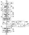
- FIG. 6 is a partial view showing steps 0 to 18 and 71 of the flowchart showing the operation in the energy saving drying mode in the air conditioner according to Embodiment 1 of the present invention
- FIG. 7 is Embodiment 1 of the present invention
- FIG. 8 is a partial view showing Step 19, Step 20 and Step S31 to Step 38 of the flowchart showing the operation in the energy saving drying mode in the air conditioner according to FIG. 8, and FIG. 8 shows energy saving in the air conditioner according to Embodiment 1 of the present invention.
- FIG. 6 is a partial view showing steps 0 to 18 and 71 of the flowchart showing the operation in the energy saving drying mode in the air conditioner according to Embodiment 1 of the present invention
- FIG. 7 is Embodiment 1 of the present invention
- FIG. 8 is a partial view showing Step 19, Step 20 and Step S31 to Step 38 of the flowchart showing the operation in the energy saving drying mode in the air conditioner according to FIG. 8, and FIG. 8 shows energy saving in the air conditioner according to Embodiment
- FIG. 9 is a partial view showing Step 21 to Step 30 of the flowchart showing the operation in the drying mode
- FIG. 9 is Step 39 of the flowchart showing the operation in the energy saving drying mode in the air conditioner according to Embodiment 1 of the present invention.
- FIG. 10 is a partial view showing steps 41 to 55 and steps 55 to 70.
- FIG. FIG. 11 (a) is a partial view showing steps 42 to 54 of the flowchart showing the operation in the energy-saving drying mode in the air conditioner according to Embodiment 1
- FIG. FIG. 11 (b) is a conceptual diagram showing another display example showing the degree of drying of the object to be dried in the air conditioner according to Embodiment 1 of the present invention.
- FIG. 10 is a partial view showing steps 41 to 55 and steps 55 to 70.
- FIG. FIG. 11 (a) is a partial view showing steps 42 to 54 of the flowchart showing the operation in the energy-saving drying mode in the air conditioner according to Embodiment 1
- FIG. 11 (b) is
- the dehumidifying means 5 In the standard drying mode, the dehumidifying means 5 is operated from the beginning of the operation, whereas in the energy saving drying mode, the dehumidifying means 5 is not operated at the beginning of the operation, and the fan motor 2a as the blowing means is operated to rotate the blowing fan 2. Only the air blowing operation is performed.
- the energy-saving drying mode it is not limited to this expression, and may be an expression representing suppression of power consumption, and may be, for example, a power saving mode or a power saving mode.
- the operation of the control circuit 7 is started by the input of the power switch 9, and the energy saving drying mode is selected from the drying modes of the object to be dried by operating the drying mode switch 11 provided in the operation unit 8. Is detected, the measurement of the total operation time T from the start of operation is started (S0), and the air direction variable means 1 is driven to enable the air to be blown from the exhaust port 103, and the fan motor 2a is driven to rotate the blower fan 2. Then, the blowing operation is started (S1). As described above, the operation of the dehumidifying means 5 is not started at this stage.
- the control circuit 7 operates the infrared sensor 6.
- the surface temperature detection range (full scanning range 200) by the infrared sensor 6 is substantially the same as the direction of the dry air B varied by the vertical direction louver 1a and the horizontal direction louver 1b, and each louver 1a, 1b. Is capable of detecting the surface temperature of the entire region within the air blowable range, and is divided into a plurality of areas (for example, the area of one section is 201) with respect to the entire scanning range 200 of the infrared sensor 6. The temperature is detected (S3 to S4).
- to-be-dried clothes such as wet clothing are evaporated by receiving air, and the surface temperature becomes lower than the ambient temperature.
- the infrared sensor 6 By detecting this low temperature range with the infrared sensor 6, it is detected that an object to be dried is arranged in that range.
- the initial drying degree of the object to be dried is displayed on the display means 12 as the object to be dried display mark 13 (S5), and the initial energy saving level is displayed on the display means 12 as the energy saving level display mark 14 (S6).
- the to-be-dried object display mark 13 displays the display 13a which shows the initial drying degree as a display at the time of starting, as shown to Fig.11 (a). 13a displays all three of the display areas divided into three.
- the shape of the to-be-dried object display mark 13 is not limited to this, What is necessary is just a shape which shows that to-be-dried object is shown, and it can display also with a figure or a character.
- the energy saving level display mark 14 is not limited to this shape as long as it can be understood that the energy saving level can be expressed. If the energy saving level changes during the process, the display changes accordingly. You may make it make it.
- control circuit 7 moves to an operation (S7) for determining the rotational speed of the blower fan 2, and counts the number of divided areas where the object to be dried is arranged ( S8) and the amount of the object to be dried is calculated (S9). If the number of counted areas is large, the amount of the object to be dried is large, and if it is small, it can be determined that the amount of the object to be dried is small.
- the control circuit 7 changes the rotation speed of the blower fan 2 according to the counted number of areas (S10a to S10d), and suppresses power consumption.
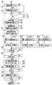
- the process of measuring the temperature and humidity of the indoor air A is entered.
- the determination of the initial humidity is performed until a predetermined time elapses (S11 to S12) so that the temperature and humidity can be stably detected. Do not move to.
- the indoor air A is taken into the air conditioner casing 100 from the suction port 101 by the rotation of the blower fan 2 described above for the initial environment determination (S13).
- the control circuit 7 reads the room temperature RT detected by the temperature sensor 3, and reads the room humidity RH1 detected by the humidity sensor 4 (S14).
- the control circuit 7 compares the detected temperature RT of the indoor air A with a predetermined temperature set in advance (S15).
- the predetermined temperature is set to 15 ° C., for example.
- RT is 15 ° C. or lower in S15
- the process proceeds to S71 to start the dehumidifying operation, and when RT is 15 ° C. or higher in S15, the process proceeds to S16. Transition.
- the control circuit 7 compares the detected humidity RH1 of the indoor air A with a predetermined humidity set in advance (S16).
- the predetermined humidity is set to 80%, for example.
- RH1 is 80% or more in S16
- the process proceeds to S71 to start the dehumidifying operation, and when RH1 is 80% or less in S16, the process proceeds to S17. Transition.
- the state of the indoor air A in the state of transition from S16 to S17 is a state in which the humidity is low and the temperature is high, so that it can be said that, for example, a wet object to be dried is relatively easy to dry.
- the process moves directly to the dehumidifying operation without continuing the blowing operation, and the object to be dried is not dried.
- the control is switched to the control for promoting the drying so that the material to be dried can be dried at the end of the operation.
- the control circuit 7 executes control to detect the maximum value RHMax (S17 to S18).
- the control circuit 7 proceeds to S33, and when the maximum humidity value RHMax is not detected, the control circuit 7 proceeds to S22.
- the maximum humidity value RHMax is detected based on whether or not the average humidity RHAve for a predetermined time, eg, 10 minutes, starts to decrease (S19 to S20). When it is detected (S31 to S32), it is determined that the maximum humidity value RHMax has been detected.
- the highest humidity value among the detected humidity values RH1 may be set as the maximum humidity value RHMax, and the humidity value RHMax when the humidity value RH1 changes from rising to falling may be used.
- the maximum value RHMax may be used.
- the process for determining the air blowing operation time is entered from S33, the control circuit 7 determines the maximum value RHMax of the humidity, measures the temperature RT of the indoor air A at that time (S34), and the object to be dried is arranged. The number of divided areas is counted again (S35). A variable H for setting the air blowing operation time is determined from the counted number of areas according to the rotational speed (S36a to S36d).
- This is a process for setting the air blowing operation time according to the rotation speed so that the drying progress is different in the same air blowing operation time when the rotation speed is lowered and the air blowing operation time is the same. is there.
- the control circuit 7 detects the change state of the maximum humidity value RHMax (S37), calculates the remaining blowing operation time Tf (S38), and proceeds to S39.
- the air blowing time Tf is set to be longer as the maximum humidity value RHMax is larger. This makes it possible to shorten the time of the dehumidifying operation which consumes a large amount of power even when the humidity is high, and thus energy saving. The effect can be obtained.
- control circuit 7 proceeds to S55, starts the dehumidifying operation, operates the blower fan 2 and the dehumidifying means 5, starts the measurement of the dehumidifying operation time TJ from the start of the dehumidifying operation (S56), and proceeds to S57. To do.
- control circuit 7 changes the display of the energy saving level display mark 14 on the display means 12 according to the rotation speed change of the blower fan 2, for example, increases or decreases the number of marks as the energy saving level becomes higher.
- the display is also changed (S61a to S61c).
- the energy saving level display mark 14 is displayed by setting the energy saving level of each operation mode in advance when each operation mode is selected, and displaying the energy saving level display mark 14 in accordance with the energy saving level. It is also possible to set a standard for selecting an energy saving operation.
- control circuit 7 determines whether or not the humidity RH1 of the indoor air A has become 50% or less after 10 minutes have passed since the start of the dehumidifying operation (S62) (S63), and the humidity RH1 of the indoor air A is 50%. If it is below, the process proceeds to S64.
- the process proceeds to S64 to enter the step of calculating the end time Y of the dehumidifying operation, and the end time Y is calculated from the dehumidifying operation time TJ from the start of the dehumidifying operation and the room temperature RT (S65), and the process proceeds to S66 and the remaining operating time of the dehumidifying operation TY is measured.
- the drying state of the object to be dried is displayed according to the progress of the operation for drying the object to be dried. Therefore, it is not necessary to move to the place where the object to be dried is placed and touch it to confirm the dry state, so that the convenience of the user can be improved.
- the display area of the object to be dried display mark 13 as shown in FIG. 11A is reduced in accordance with the progress of drying.
- the display method is not limited to this display method.
- the display area may be increased to 13e, 13f, and 13g according to the progress of drying from the state that is not displayed as 13d shown in FIG. The usability can be improved as well.
- the numerical values such as the predetermined time, temperature, and humidity, which are the reference of the control used in the description of the first embodiment, are examples, and are not limited to these numerical values.
- the predetermined numerical values serving as these standards can be appropriately set within a range that does not depart from the scope of the present invention in accordance with the environment in which the air conditioner is used and the user's preference.
- the present invention can be used for an air conditioner that dehumidifies indoor moisture, and in particular, an air conditioner that has a function of drying laundry that is dried to be dried indoors.
- 1 Wind direction varying means 1a Longitudinal louver, 1b Lateral louver, 1c Longitudinal variable motor, 1d Lateral variable motor, 2 Blower fan, 2a Fan motor, 3 Temperature sensor, 4 Humidity sensor, 5 Dehumidifying means, 6 Infrared sensor , 6a Infrared absorbing film, 6b Thermistor, 7 Control circuit, 8 Operation unit, 9 Power switch, 10 Dehumidification mode switch, 11 Drying mode switch, 12 Display means, 13 Drying object display mark, 13a-13g Drying object display mark Display example, 14 energy saving level display mark, 100 air conditioner housing, 101 suction port, 102 water storage tank, 103 exhaust port, 200 full scanning range, 201 divided area, A room air, B dry air.
Priority Applications (4)
| Application Number | Priority Date | Filing Date | Title |
|---|---|---|---|
| JP2014507518A JP5904272B2 (ja) | 2012-03-29 | 2013-02-19 | 空気調和機 |
| CN201380014912.8A CN104246059B (zh) | 2012-03-29 | 2013-02-19 | 空气调节机 |
| EP13768677.0A EP2832920A4 (en) | 2012-03-29 | 2013-02-19 | AIR CONDITIONING APPARATUS |
| HK15101696.8A HK1201302A1 (zh) | 2012-03-29 | 2015-02-13 | 空氣調節機 |
Applications Claiming Priority (2)
| Application Number | Priority Date | Filing Date | Title |
|---|---|---|---|
| JP2012-076287 | 2012-03-29 | ||
| JP2012076287 | 2012-03-29 |
Publications (1)
| Publication Number | Publication Date |
|---|---|
| WO2013145945A1 true WO2013145945A1 (ja) | 2013-10-03 |
Family
ID=49259227
Family Applications (1)
| Application Number | Title | Priority Date | Filing Date |
|---|---|---|---|
| PCT/JP2013/053997 WO2013145945A1 (ja) | 2012-03-29 | 2013-02-19 | 空気調和機 |
Country Status (6)
| Country | Link |
|---|---|
| EP (1) | EP2832920A4 (zh) |
| JP (1) | JP5904272B2 (zh) |
| CN (1) | CN104246059B (zh) |
| HK (1) | HK1201302A1 (zh) |
| TW (1) | TWI608196B (zh) |
| WO (1) | WO2013145945A1 (zh) |
Cited By (4)
| Publication number | Priority date | Publication date | Assignee | Title |
|---|---|---|---|---|
| JP2016166708A (ja) * | 2015-03-10 | 2016-09-15 | ジョンソンコントロールズ ヒタチ エア コンディショニング テクノロジー(ホンコン)リミテッド | 空気調和機 |
| WO2018155291A1 (ja) * | 2017-02-24 | 2018-08-30 | パナソニックIpマネジメント株式会社 | 水分量センサ及び衣類乾燥装置 |
| CN109883159A (zh) * | 2019-03-25 | 2019-06-14 | 杨鑫 | 一种对流加压风式热泵除湿烘干一体机 |
| CN114811834A (zh) * | 2021-04-14 | 2022-07-29 | 宁波奥克斯电气股份有限公司 | 带烘干功能的空调控制方法、装置、空调器和计算机可读存储介质 |
Families Citing this family (4)
| Publication number | Priority date | Publication date | Assignee | Title |
|---|---|---|---|---|
| WO2017197612A1 (zh) * | 2016-05-18 | 2017-11-23 | 友隆电器工业(深圳)有限公司 | 干衣机的烘干控制方法及系统 |
| WO2021212458A1 (en) | 2020-04-24 | 2021-10-28 | Midea Group Co., Ltd. | Dehumidifier with condensate tank |
| CN114754478B (zh) * | 2022-04-29 | 2022-12-20 | 南通东帝纺织品有限公司 | 一种纺织厂温湿度自动控制系统 |
| CN115013933B (zh) * | 2022-07-01 | 2024-04-02 | 珠海格力电器股份有限公司 | 空调的除菌方法、控制器、空调和除菌系统 |
Citations (6)
| Publication number | Priority date | Publication date | Assignee | Title |
|---|---|---|---|---|
| JPH10170050A (ja) * | 1996-12-10 | 1998-06-26 | Kusatsu Denki Kk | 浴室換気乾燥機 |
| JP2004226050A (ja) * | 2003-01-27 | 2004-08-12 | Lg Electronics Inc | 空調機器 |
| JP2006068196A (ja) * | 2004-09-01 | 2006-03-16 | Matsushita Electric Ind Co Ltd | 浴室衣類乾燥装置 |
| JP2007181585A (ja) * | 2006-01-10 | 2007-07-19 | Matsushita Electric Ind Co Ltd | 除湿機 |
| JP2007240100A (ja) | 2006-03-10 | 2007-09-20 | Matsushita Electric Ind Co Ltd | 除湿機 |
| JP2009219582A (ja) * | 2008-03-14 | 2009-10-01 | Panasonic Corp | 除湿装置 |
Family Cites Families (10)
| Publication number | Priority date | Publication date | Assignee | Title |
|---|---|---|---|---|
| JPH11156097A (ja) * | 1997-11-29 | 1999-06-15 | Toto Ltd | 浴室衣類乾燥装置 |
| JP2003075370A (ja) * | 2001-09-07 | 2003-03-12 | Toto Ltd | 乾燥状態測定装置 |
| JP2009089995A (ja) * | 2007-10-11 | 2009-04-30 | Panasonic Corp | 除湿装置 |
| CN102839525B (zh) * | 2008-03-13 | 2015-04-01 | 松下电器产业株式会社 | 衣物干燥机以及衣物干燥机的风向变更装置 |
| JP5256794B2 (ja) * | 2008-03-13 | 2013-08-07 | パナソニック株式会社 | 衣類乾燥の制御方法および衣類乾燥機 |
| JP2009247469A (ja) * | 2008-04-03 | 2009-10-29 | Panasonic Corp | 除湿装置 |
| JP4685913B2 (ja) * | 2008-11-05 | 2011-05-18 | 三菱電機株式会社 | 除湿機 |
| JP5310653B2 (ja) * | 2009-11-09 | 2013-10-09 | 三菱電機株式会社 | 除湿機および除湿機の制御方法 |
| JP5387462B2 (ja) * | 2010-03-15 | 2014-01-15 | 三菱電機株式会社 | 除湿機 |
| EP2813775B1 (en) * | 2012-01-31 | 2019-03-27 | Mitsubishi Electric Corporation | Dehumidifier |
-
2013
- 2013-02-19 WO PCT/JP2013/053997 patent/WO2013145945A1/ja active Application Filing
- 2013-02-19 JP JP2014507518A patent/JP5904272B2/ja active Active
- 2013-02-19 EP EP13768677.0A patent/EP2832920A4/en not_active Withdrawn
- 2013-02-19 CN CN201380014912.8A patent/CN104246059B/zh not_active Expired - Fee Related
- 2013-03-06 TW TW102107802A patent/TWI608196B/zh not_active IP Right Cessation
-
2015
- 2015-02-13 HK HK15101696.8A patent/HK1201302A1/zh not_active IP Right Cessation
Patent Citations (6)
| Publication number | Priority date | Publication date | Assignee | Title |
|---|---|---|---|---|
| JPH10170050A (ja) * | 1996-12-10 | 1998-06-26 | Kusatsu Denki Kk | 浴室換気乾燥機 |
| JP2004226050A (ja) * | 2003-01-27 | 2004-08-12 | Lg Electronics Inc | 空調機器 |
| JP2006068196A (ja) * | 2004-09-01 | 2006-03-16 | Matsushita Electric Ind Co Ltd | 浴室衣類乾燥装置 |
| JP2007181585A (ja) * | 2006-01-10 | 2007-07-19 | Matsushita Electric Ind Co Ltd | 除湿機 |
| JP2007240100A (ja) | 2006-03-10 | 2007-09-20 | Matsushita Electric Ind Co Ltd | 除湿機 |
| JP2009219582A (ja) * | 2008-03-14 | 2009-10-01 | Panasonic Corp | 除湿装置 |
Non-Patent Citations (1)
| Title |
|---|
| See also references of EP2832920A4 |
Cited By (7)
| Publication number | Priority date | Publication date | Assignee | Title |
|---|---|---|---|---|
| JP2016166708A (ja) * | 2015-03-10 | 2016-09-15 | ジョンソンコントロールズ ヒタチ エア コンディショニング テクノロジー(ホンコン)リミテッド | 空気調和機 |
| WO2018155291A1 (ja) * | 2017-02-24 | 2018-08-30 | パナソニックIpマネジメント株式会社 | 水分量センサ及び衣類乾燥装置 |
| JPWO2018155291A1 (ja) * | 2017-02-24 | 2019-11-07 | パナソニックIpマネジメント株式会社 | 水分量センサ及び衣類乾燥装置 |
| CN109883159A (zh) * | 2019-03-25 | 2019-06-14 | 杨鑫 | 一种对流加压风式热泵除湿烘干一体机 |
| CN109883159B (zh) * | 2019-03-25 | 2024-03-29 | 甘肃一德新能源设备有限公司 | 一种对流加压风式热泵除湿烘干一体机 |
| CN114811834A (zh) * | 2021-04-14 | 2022-07-29 | 宁波奥克斯电气股份有限公司 | 带烘干功能的空调控制方法、装置、空调器和计算机可读存储介质 |
| CN114811834B (zh) * | 2021-04-14 | 2023-07-18 | 宁波奥克斯电气股份有限公司 | 带烘干功能的空调控制方法、装置、空调器 |
Also Published As
| Publication number | Publication date |
|---|---|
| TWI608196B (zh) | 2017-12-11 |
| CN104246059B (zh) | 2017-05-31 |
| TW201400770A (zh) | 2014-01-01 |
| CN104246059A (zh) | 2014-12-24 |
| JP5904272B2 (ja) | 2016-04-13 |
| JPWO2013145945A1 (ja) | 2015-12-10 |
| EP2832920A1 (en) | 2015-02-04 |
| HK1201302A1 (zh) | 2015-08-28 |
| EP2832920A4 (en) | 2015-12-23 |
Similar Documents
| Publication | Publication Date | Title |
|---|---|---|
| JP5904272B2 (ja) | 空気調和機 | |
| JP6138112B2 (ja) | 空気調和機 | |
| JP5843001B2 (ja) | 除湿機 | |
| JP6104303B2 (ja) | 空気調和機 | |
| JP5839051B2 (ja) | 除湿機 | |
| JP5839113B2 (ja) | 空気調和機 | |
| JPWO2011111514A1 (ja) | 除湿機 | |
| JP5610797B2 (ja) | 除湿機 | |
| NZ625338B2 (en) | Dehumidifier | |
| NZ613995B2 (en) | Air-conditioning apparatus |
Legal Events
| Date | Code | Title | Description |
|---|---|---|---|
| 121 | Ep: the epo has been informed by wipo that ep was designated in this application |
Ref document number: 13768677 Country of ref document: EP Kind code of ref document: A1 |
|
| ENP | Entry into the national phase |
Ref document number: 2014507518 Country of ref document: JP Kind code of ref document: A |
|
| WWE | Wipo information: entry into national phase |
Ref document number: 2013768677 Country of ref document: EP |
|
| NENP | Non-entry into the national phase |
Ref country code: DE |