WO2013145945A1 - Air conditioner - Google Patents
Air conditioner Download PDFInfo
- Publication number
- WO2013145945A1 WO2013145945A1 PCT/JP2013/053997 JP2013053997W WO2013145945A1 WO 2013145945 A1 WO2013145945 A1 WO 2013145945A1 JP 2013053997 W JP2013053997 W JP 2013053997W WO 2013145945 A1 WO2013145945 A1 WO 2013145945A1
- Authority
- WO
- WIPO (PCT)
- Prior art keywords
- air
- temperature
- humidity
- display
- dried
- Prior art date
Links
Images


Classifications
-
- D—TEXTILES; PAPER
- D06—TREATMENT OF TEXTILES OR THE LIKE; LAUNDERING; FLEXIBLE MATERIALS NOT OTHERWISE PROVIDED FOR
- D06F—LAUNDERING, DRYING, IRONING, PRESSING OR FOLDING TEXTILE ARTICLES
- D06F58/00—Domestic laundry dryers
-
- F—MECHANICAL ENGINEERING; LIGHTING; HEATING; WEAPONS; BLASTING
- F24—HEATING; RANGES; VENTILATING
- F24F—AIR-CONDITIONING; AIR-HUMIDIFICATION; VENTILATION; USE OF AIR CURRENTS FOR SCREENING
- F24F11/00—Control or safety arrangements
- F24F11/30—Control or safety arrangements for purposes related to the operation of the system, e.g. for safety or monitoring
- F24F11/46—Improving electric energy efficiency or saving
-
- F—MECHANICAL ENGINEERING; LIGHTING; HEATING; WEAPONS; BLASTING
- F24—HEATING; RANGES; VENTILATING
- F24F—AIR-CONDITIONING; AIR-HUMIDIFICATION; VENTILATION; USE OF AIR CURRENTS FOR SCREENING
- F24F11/00—Control or safety arrangements
- F24F11/50—Control or safety arrangements characterised by user interfaces or communication
- F24F11/52—Indication arrangements, e.g. displays
- F24F11/523—Indication arrangements, e.g. displays for displaying temperature data
-
- F—MECHANICAL ENGINEERING; LIGHTING; HEATING; WEAPONS; BLASTING
- F24—HEATING; RANGES; VENTILATING
- F24F—AIR-CONDITIONING; AIR-HUMIDIFICATION; VENTILATION; USE OF AIR CURRENTS FOR SCREENING
- F24F11/00—Control or safety arrangements
- F24F11/70—Control systems characterised by their outputs; Constructional details thereof
- F24F11/72—Control systems characterised by their outputs; Constructional details thereof for controlling the supply of treated air, e.g. its pressure
- F24F11/74—Control systems characterised by their outputs; Constructional details thereof for controlling the supply of treated air, e.g. its pressure for controlling air flow rate or air velocity
- F24F11/77—Control systems characterised by their outputs; Constructional details thereof for controlling the supply of treated air, e.g. its pressure for controlling air flow rate or air velocity by controlling the speed of ventilators
-
- F—MECHANICAL ENGINEERING; LIGHTING; HEATING; WEAPONS; BLASTING
- F24—HEATING; RANGES; VENTILATING
- F24F—AIR-CONDITIONING; AIR-HUMIDIFICATION; VENTILATION; USE OF AIR CURRENTS FOR SCREENING
- F24F11/00—Control or safety arrangements
- F24F11/70—Control systems characterised by their outputs; Constructional details thereof
- F24F11/72—Control systems characterised by their outputs; Constructional details thereof for controlling the supply of treated air, e.g. its pressure
- F24F11/79—Control systems characterised by their outputs; Constructional details thereof for controlling the supply of treated air, e.g. its pressure for controlling the direction of the supplied air
-
- F—MECHANICAL ENGINEERING; LIGHTING; HEATING; WEAPONS; BLASTING
- F24—HEATING; RANGES; VENTILATING
- F24F—AIR-CONDITIONING; AIR-HUMIDIFICATION; VENTILATION; USE OF AIR CURRENTS FOR SCREENING
- F24F11/00—Control or safety arrangements
- F24F11/89—Arrangement or mounting of control or safety devices
-
- F—MECHANICAL ENGINEERING; LIGHTING; HEATING; WEAPONS; BLASTING
- F24—HEATING; RANGES; VENTILATING
- F24F—AIR-CONDITIONING; AIR-HUMIDIFICATION; VENTILATION; USE OF AIR CURRENTS FOR SCREENING
- F24F3/00—Air-conditioning systems in which conditioned primary air is supplied from one or more central stations to distributing units in the rooms or spaces where it may receive secondary treatment; Apparatus specially designed for such systems
- F24F3/12—Air-conditioning systems in which conditioned primary air is supplied from one or more central stations to distributing units in the rooms or spaces where it may receive secondary treatment; Apparatus specially designed for such systems characterised by the treatment of the air otherwise than by heating and cooling
- F24F3/14—Air-conditioning systems in which conditioned primary air is supplied from one or more central stations to distributing units in the rooms or spaces where it may receive secondary treatment; Apparatus specially designed for such systems characterised by the treatment of the air otherwise than by heating and cooling by humidification; by dehumidification
-
- F—MECHANICAL ENGINEERING; LIGHTING; HEATING; WEAPONS; BLASTING
- F26—DRYING
- F26B—DRYING SOLID MATERIALS OR OBJECTS BY REMOVING LIQUID THEREFROM
- F26B21/00—Arrangements or duct systems, e.g. in combination with pallet boxes, for supplying and controlling air or gases for drying solid materials or objects
- F26B21/06—Controlling, e.g. regulating, parameters of gas supply
- F26B21/08—Humidity
- F26B21/083—Humidity by using sorbent or hygroscopic materials, e.g. chemical substances, molecular sieves
-
- F—MECHANICAL ENGINEERING; LIGHTING; HEATING; WEAPONS; BLASTING
- F26—DRYING
- F26B—DRYING SOLID MATERIALS OR OBJECTS BY REMOVING LIQUID THEREFROM
- F26B21/00—Arrangements or duct systems, e.g. in combination with pallet boxes, for supplying and controlling air or gases for drying solid materials or objects
- F26B21/06—Controlling, e.g. regulating, parameters of gas supply
- F26B21/10—Temperature; Pressure
-
- F—MECHANICAL ENGINEERING; LIGHTING; HEATING; WEAPONS; BLASTING
- F26—DRYING
- F26B—DRYING SOLID MATERIALS OR OBJECTS BY REMOVING LIQUID THEREFROM
- F26B25/00—Details of general application not covered by group F26B21/00 or F26B23/00
- F26B25/22—Controlling the drying process in dependence on liquid content of solid materials or objects
- F26B25/225—Controlling the drying process in dependence on liquid content of solid materials or objects by repeated or continuous weighing of the material or a sample thereof
-
- F—MECHANICAL ENGINEERING; LIGHTING; HEATING; WEAPONS; BLASTING
- F26—DRYING
- F26B—DRYING SOLID MATERIALS OR OBJECTS BY REMOVING LIQUID THEREFROM
- F26B9/00—Machines or apparatus for drying solid materials or objects at rest or with only local agitation; Domestic airing cupboards
- F26B9/06—Machines or apparatus for drying solid materials or objects at rest or with only local agitation; Domestic airing cupboards in stationary drums or chambers
-
- D—TEXTILES; PAPER
- D06—TREATMENT OF TEXTILES OR THE LIKE; LAUNDERING; FLEXIBLE MATERIALS NOT OTHERWISE PROVIDED FOR
- D06F—LAUNDERING, DRYING, IRONING, PRESSING OR FOLDING TEXTILE ARTICLES
- D06F2103/00—Parameters monitored or detected for the control of domestic laundry washing machines, washer-dryers or laundry dryers
- D06F2103/02—Characteristics of laundry or load
- D06F2103/08—Humidity
-
- D—TEXTILES; PAPER
- D06—TREATMENT OF TEXTILES OR THE LIKE; LAUNDERING; FLEXIBLE MATERIALS NOT OTHERWISE PROVIDED FOR
- D06F—LAUNDERING, DRYING, IRONING, PRESSING OR FOLDING TEXTILE ARTICLES
- D06F2103/00—Parameters monitored or detected for the control of domestic laundry washing machines, washer-dryers or laundry dryers
- D06F2103/02—Characteristics of laundry or load
- D06F2103/12—Temperature
-
- D—TEXTILES; PAPER
- D06—TREATMENT OF TEXTILES OR THE LIKE; LAUNDERING; FLEXIBLE MATERIALS NOT OTHERWISE PROVIDED FOR
- D06F—LAUNDERING, DRYING, IRONING, PRESSING OR FOLDING TEXTILE ARTICLES
- D06F2103/00—Parameters monitored or detected for the control of domestic laundry washing machines, washer-dryers or laundry dryers
- D06F2103/28—Air properties
- D06F2103/32—Temperature
-
- D—TEXTILES; PAPER
- D06—TREATMENT OF TEXTILES OR THE LIKE; LAUNDERING; FLEXIBLE MATERIALS NOT OTHERWISE PROVIDED FOR
- D06F—LAUNDERING, DRYING, IRONING, PRESSING OR FOLDING TEXTILE ARTICLES
- D06F2103/00—Parameters monitored or detected for the control of domestic laundry washing machines, washer-dryers or laundry dryers
- D06F2103/28—Air properties
- D06F2103/34—Humidity
-
- D—TEXTILES; PAPER
- D06—TREATMENT OF TEXTILES OR THE LIKE; LAUNDERING; FLEXIBLE MATERIALS NOT OTHERWISE PROVIDED FOR
- D06F—LAUNDERING, DRYING, IRONING, PRESSING OR FOLDING TEXTILE ARTICLES
- D06F2103/00—Parameters monitored or detected for the control of domestic laundry washing machines, washer-dryers or laundry dryers
- D06F2103/28—Air properties
- D06F2103/36—Flow or velocity
-
- D—TEXTILES; PAPER
- D06—TREATMENT OF TEXTILES OR THE LIKE; LAUNDERING; FLEXIBLE MATERIALS NOT OTHERWISE PROVIDED FOR
- D06F—LAUNDERING, DRYING, IRONING, PRESSING OR FOLDING TEXTILE ARTICLES
- D06F2103/00—Parameters monitored or detected for the control of domestic laundry washing machines, washer-dryers or laundry dryers
- D06F2103/64—Radiation, e.g. microwaves
-
- D—TEXTILES; PAPER
- D06—TREATMENT OF TEXTILES OR THE LIKE; LAUNDERING; FLEXIBLE MATERIALS NOT OTHERWISE PROVIDED FOR
- D06F—LAUNDERING, DRYING, IRONING, PRESSING OR FOLDING TEXTILE ARTICLES
- D06F2105/00—Systems or parameters controlled or affected by the control systems of washing machines, washer-dryers or laundry dryers
- D06F2105/16—Air properties
- D06F2105/24—Flow or velocity
-
- D—TEXTILES; PAPER
- D06—TREATMENT OF TEXTILES OR THE LIKE; LAUNDERING; FLEXIBLE MATERIALS NOT OTHERWISE PROVIDED FOR
- D06F—LAUNDERING, DRYING, IRONING, PRESSING OR FOLDING TEXTILE ARTICLES
- D06F2105/00—Systems or parameters controlled or affected by the control systems of washing machines, washer-dryers or laundry dryers
- D06F2105/30—Blowers
-
- D—TEXTILES; PAPER
- D06—TREATMENT OF TEXTILES OR THE LIKE; LAUNDERING; FLEXIBLE MATERIALS NOT OTHERWISE PROVIDED FOR
- D06F—LAUNDERING, DRYING, IRONING, PRESSING OR FOLDING TEXTILE ARTICLES
- D06F2105/00—Systems or parameters controlled or affected by the control systems of washing machines, washer-dryers or laundry dryers
- D06F2105/58—Indications or alarms to the control system or to the user
-
- D—TEXTILES; PAPER
- D06—TREATMENT OF TEXTILES OR THE LIKE; LAUNDERING; FLEXIBLE MATERIALS NOT OTHERWISE PROVIDED FOR
- D06F—LAUNDERING, DRYING, IRONING, PRESSING OR FOLDING TEXTILE ARTICLES
- D06F34/00—Details of control systems for washing machines, washer-dryers or laundry dryers
- D06F34/28—Arrangements for program selection, e.g. control panels therefor; Arrangements for indicating program parameters, e.g. the selected program or its progress
- D06F34/32—Arrangements for program selection, e.g. control panels therefor; Arrangements for indicating program parameters, e.g. the selected program or its progress characterised by graphical features, e.g. touchscreens
-
- D—TEXTILES; PAPER
- D06—TREATMENT OF TEXTILES OR THE LIKE; LAUNDERING; FLEXIBLE MATERIALS NOT OTHERWISE PROVIDED FOR
- D06F—LAUNDERING, DRYING, IRONING, PRESSING OR FOLDING TEXTILE ARTICLES
- D06F58/00—Domestic laundry dryers
- D06F58/32—Control of operations performed in domestic laundry dryers
- D06F58/34—Control of operations performed in domestic laundry dryers characterised by the purpose or target of the control
- D06F58/36—Control of operational steps, e.g. for optimisation or improvement of operational steps depending on the condition of the laundry
- D06F58/38—Control of operational steps, e.g. for optimisation or improvement of operational steps depending on the condition of the laundry of drying, e.g. to achieve the target humidity
-
- F—MECHANICAL ENGINEERING; LIGHTING; HEATING; WEAPONS; BLASTING
- F24—HEATING; RANGES; VENTILATING
- F24F—AIR-CONDITIONING; AIR-HUMIDIFICATION; VENTILATION; USE OF AIR CURRENTS FOR SCREENING
- F24F11/00—Control or safety arrangements
- F24F11/30—Control or safety arrangements for purposes related to the operation of the system, e.g. for safety or monitoring
- F24F11/46—Improving electric energy efficiency or saving
- F24F11/47—Responding to energy costs
-
- F—MECHANICAL ENGINEERING; LIGHTING; HEATING; WEAPONS; BLASTING
- F24—HEATING; RANGES; VENTILATING
- F24F—AIR-CONDITIONING; AIR-HUMIDIFICATION; VENTILATION; USE OF AIR CURRENTS FOR SCREENING
- F24F11/00—Control or safety arrangements
- F24F11/50—Control or safety arrangements characterised by user interfaces or communication
- F24F11/52—Indication arrangements, e.g. displays
-
- F—MECHANICAL ENGINEERING; LIGHTING; HEATING; WEAPONS; BLASTING
- F24—HEATING; RANGES; VENTILATING
- F24F—AIR-CONDITIONING; AIR-HUMIDIFICATION; VENTILATION; USE OF AIR CURRENTS FOR SCREENING
- F24F3/00—Air-conditioning systems in which conditioned primary air is supplied from one or more central stations to distributing units in the rooms or spaces where it may receive secondary treatment; Apparatus specially designed for such systems
- F24F3/12—Air-conditioning systems in which conditioned primary air is supplied from one or more central stations to distributing units in the rooms or spaces where it may receive secondary treatment; Apparatus specially designed for such systems characterised by the treatment of the air otherwise than by heating and cooling
- F24F3/14—Air-conditioning systems in which conditioned primary air is supplied from one or more central stations to distributing units in the rooms or spaces where it may receive secondary treatment; Apparatus specially designed for such systems characterised by the treatment of the air otherwise than by heating and cooling by humidification; by dehumidification
- F24F2003/144—Air-conditioning systems in which conditioned primary air is supplied from one or more central stations to distributing units in the rooms or spaces where it may receive secondary treatment; Apparatus specially designed for such systems characterised by the treatment of the air otherwise than by heating and cooling by humidification; by dehumidification by dehumidification only
-
- F—MECHANICAL ENGINEERING; LIGHTING; HEATING; WEAPONS; BLASTING
- F24—HEATING; RANGES; VENTILATING
- F24F—AIR-CONDITIONING; AIR-HUMIDIFICATION; VENTILATION; USE OF AIR CURRENTS FOR SCREENING
- F24F2110/00—Control inputs relating to air properties
- F24F2110/10—Temperature
-
- F—MECHANICAL ENGINEERING; LIGHTING; HEATING; WEAPONS; BLASTING
- F24—HEATING; RANGES; VENTILATING
- F24F—AIR-CONDITIONING; AIR-HUMIDIFICATION; VENTILATION; USE OF AIR CURRENTS FOR SCREENING
- F24F2110/00—Control inputs relating to air properties
- F24F2110/20—Humidity
-
- Y—GENERAL TAGGING OF NEW TECHNOLOGICAL DEVELOPMENTS; GENERAL TAGGING OF CROSS-SECTIONAL TECHNOLOGIES SPANNING OVER SEVERAL SECTIONS OF THE IPC; TECHNICAL SUBJECTS COVERED BY FORMER USPC CROSS-REFERENCE ART COLLECTIONS [XRACs] AND DIGESTS
- Y02—TECHNOLOGIES OR APPLICATIONS FOR MITIGATION OR ADAPTATION AGAINST CLIMATE CHANGE
- Y02B—CLIMATE CHANGE MITIGATION TECHNOLOGIES RELATED TO BUILDINGS, e.g. HOUSING, HOUSE APPLIANCES OR RELATED END-USER APPLICATIONS
- Y02B30/00—Energy efficient heating, ventilation or air conditioning [HVAC]
- Y02B30/70—Efficient control or regulation technologies, e.g. for control of refrigerant flow, motor or heating
Definitions
- the present invention relates to an air conditioner that dehumidifies indoor moisture, and more particularly to an air conditioner that has a function of drying laundry that is to be dried in a room.
- the control means compares the temperature detection result by the infrared detection means and the indoor atmosphere temperature detection result by the temperature detection means, thereby recognizing a decrease in sensible heat due to moisture evaporation absorbed by the object to be dried.
- positioning range of a to-be-dried object for example, refer patent document 1.
- the present invention has been made to solve the above-described problems, and a user-friendly air conditioner that allows the user to easily confirm the progress of the dry state of the object to be dried by simply looking at the display is obtained. For the purpose.
- An air conditioner includes a dehumidifying unit that removes moisture contained in the air, and a motor and a blower fan that sucks indoor air and blows dry air obtained by passing the air through the dehumidifying unit.
- a display means for displaying information on one or both sides, a blower means, a temperature detection means, and a control means for controlling the display means, the control means such as clothing wet from the surface temperature detected by the surface temperature detection means It is detected within a predetermined range that the object to be dried is arranged, and the dry state of the object to be dried is displayed on the display means according to the detection result.
- the display since the dry state of the object to be dried is displayed on the display means according to the detection result of the temperature and humidity, the display can be viewed without the user touching and confirming the object to be dried. As a result, the progress of the dry state of the object to be dried can be easily confirmed, and the usability is improved.
- Step 19 It is a partial view showing Step 19, Step 20 and Step 31 to Step 38 of the flowchart showing the operation in the energy saving drying mode in the air conditioner according to Embodiment 1 of the present invention. It is a fragmentary figure which shows step 21 to step 30 of the flowchart which shows the operation
- FIG. 1 is an external perspective view showing an air conditioner according to Embodiment 1 of the present invention
- FIG. 2 is a top view of a display unit and an operation unit of the air conditioner according to Embodiment 1 of the present invention as viewed from above.
- 3 is a schematic configuration diagram showing the inside of the air conditioner according to Embodiment 1 of the present invention
- FIG. 4 is an enlarged schematic perspective view showing the wind direction changing means of FIG. 1
- FIG. 5 is Embodiment 1 of the present invention. It is a conceptual diagram which shows the detection range of the infrared sensor of the air conditioner which concerns on.
- An air conditioner according to Embodiment 1 of the present invention includes an air conditioner housing 100 configured to be independent as shown in FIG. 1, and a suction port for taking indoor air A into the air conditioner housing 100. 101, a water storage tank 102 for storing moisture removed from the air taken into the suction port 101, and an exhaust port 103 for discharging the dry air B from which moisture has been removed from the air conditioner housing 100 to the room. ing.
- the exhaust port 103 is provided with a wind direction varying means 1 capable of varying the wind direction of the dry air B.
- the wind direction varying means 1 varies the vertical direction louver 1a that varies the vertical direction and the horizontal direction. And a lateral louver 1b.
- the water storage tank 102 is detachably attached to the air conditioner housing 100.
- an operation unit 8 and display means 12 for displaying various information such as operation status, temperature, and humidity are provided on the upper surface of the air conditioner housing 100.
- a power switch 9, a dehumidifying mode switch 10, and a drying mode switch 11 are provided.
- the above-described air conditioner includes a blower that constitutes a blower that generates a series of airflows that sucks the indoor air A from the suction port 101 and discharges the dry air B from the exhaust port 103.
- Fan 2 fan motor 2 a that rotates blower fan 2
- temperature sensor 3 temperature detection means
- humidity sensor that detects the humidity of room air A 4 (humidity detecting means)
- dehumidifying means 5 for generating dry air B by removing moisture contained in the room air A.
- a longitudinal variable motor 1c that varies the vertical louver 1a constituting the wind direction varying means 1 in the vertical direction
- a lateral variable motor 1d that varies the lateral louver 1b constituting the wind direction varying means 1 in the horizontal direction
- An infrared sensor 6 serving as a surface temperature detecting means and a control circuit 7 including a control means for controlling the wind direction varying means 1 and controlling the infrared sensor 6 serving as a surface temperature detecting means are provided.
- Various sensors such as the temperature sensor 3, the humidity sensor 4, and the infrared sensor 6 described above are controlled by the control circuit 7 to detect various data, and the control circuit 7 further determines the dehumidifying means 5 based on the detection results. And drive of the fan motor 2a, the display means 12, and the like are controlled.
- the dehumidifying means 5 only needs to be capable of removing moisture in the air and condensing it.
- a method of constituting a heat pump circuit and condensing moisture in the air in an evaporator In addition, a desiccant method in which moisture in the air removed by the adsorbent is condensed by a heat exchanger is used.
- the water removed from the room air A by the dehumidifying means 5 is stored in the water storage tank 102 as condensed water C.
- the vertical louver 1a has a rectangular opening extending in the width direction of the air conditioner casing 100, and is variable in the vertical direction with the rotational axis of the vertical variable motor 1c described above as a substantial axis. It is configured to be possible.
- the horizontal louvers 1b are arranged at equal intervals in the vertical louver 1a, and are pivotally supported so as to be variable in the horizontal direction on the side opposite to the opening of the vertical louver 1a. It is configured to work together.
- the infrared sensor 6 is attached to one side of a substantially central lateral louver 1b disposed in the longitudinal louver 1a. Thereby, the detection range of the surface temperature by the infrared sensor 6 becomes substantially the same as the direction of the dry air B which is varied by the air direction varying means 1.
- the infrared sensor 6 is used for objects in all areas within the range in which the wind direction changing means 1 can blow air, such as wet clothes and towels after washing (hereinafter collectively referred to as “objects to be dried”).
- the surface temperature can be detected.
- the above-described infrared sensor 6 uses, for example, a thermoelectromotive force effect, and detects the temperature of the infrared absorption film 6a that receives thermal radiation (infrared rays) emitted from the surface of a predetermined region, and the temperature of the infrared absorption film 6a. And the thermistor 6b (see FIGS. 3 and 4).
- the infrared sensor 6 has a difference between the temperature of the heat-sensitive part of the infrared absorption film 6a that rises in temperature by absorbing thermal radiation (hot contact) and the temperature of the infrared absorption film 6a detected by the thermistor 6b (cold contact). Is converted into an electrical signal such as a voltage and input to the control circuit 7. The surface temperature of a predetermined region can be detected from the magnitude of this electrical signal.
- the entire scanning range 200 is a planar area that extends in the horizontal direction (horizontal direction) and the vertical direction (vertical direction). It becomes.
- This infrared sensor 6 divides the entire scanning range 200 into a plurality of horizontal and vertical directions. Thereby, a detailed temperature map can be created for a wide range of regions.
- the wind direction varying means 1 is driven so that the humidity becomes the optimum humidity so that air can be blown from the exhaust port 103, the fan motor 2a is driven to rotate the blower fan 2, and the dehumidifying means 5 is driven.
- control circuit 7 drives the vertical direction variable motor 1c and the horizontal direction variable motor 1d of the wind direction varying means 1 so that the air is blown in the direction of a desired area in the room.
- the indoor air A is taken into the air conditioner casing 100 from the suction port 101, and the indoor temperature and humidity are detected by the temperature sensor 3 and the humidity sensor 4, respectively, and then dehumidified by the dehumidifying means 5. It becomes dry air B and is blown out into the room from the exhaust port 103.
- control circuit 7 is started by an input of the power switch 9 shown in FIG. 2, and by operating a drying mode switch 11 provided in the operation unit 8, for example, to-be-dried typified by laundry such as clothes.
- a drying mode switch 11 provided in the operation unit 8 for example, to-be-dried typified by laundry such as clothes.
- control circuit 7 reads the indoor humidity from the indoor air A taken into the air conditioner casing 100 via the humidity sensor 4 and determines whether the humidity is higher than a predetermined humidity. judge.
- the predetermined humidity is numerical data set in advance corresponding to the indoor temperature detected by the temperature sensor 3, and is stored as numerical data in a storage means (not shown) included in the control circuit 7. It is read by the control circuit 7 as required.
- the fan motor 2a and the wind direction varying means are set so that the dehumidifying means 5 has the maximum dehumidifying capacity until the indoor humidity is reduced to the same value or less as the predetermined humidity. 1 is controlled.
- the control circuit 7 detects the surface temperature for each of the plurality of divided areas (201) using the infrared sensor 6 when the indoor humidity is reduced to the same value or less as the predetermined humidity by the control described above.
- the range in which the object to be dried is located is specified from the detection result of the surface temperature, and the vertical direction variable motor 1c and the horizontal direction variable motor 1d are controlled so that the dry air B hits the range, and each louver 1a, 1b is controlled. Direct toward the material to be dried.
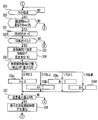
- FIG. 6 is a partial view showing steps 0 to 18 and 71 of the flowchart showing the operation in the energy saving drying mode in the air conditioner according to Embodiment 1 of the present invention
- FIG. 7 is Embodiment 1 of the present invention
- FIG. 8 is a partial view showing Step 19, Step 20 and Step S31 to Step 38 of the flowchart showing the operation in the energy saving drying mode in the air conditioner according to FIG. 8, and FIG. 8 shows energy saving in the air conditioner according to Embodiment 1 of the present invention.
- FIG. 6 is a partial view showing steps 0 to 18 and 71 of the flowchart showing the operation in the energy saving drying mode in the air conditioner according to Embodiment 1 of the present invention
- FIG. 7 is Embodiment 1 of the present invention
- FIG. 8 is a partial view showing Step 19, Step 20 and Step S31 to Step 38 of the flowchart showing the operation in the energy saving drying mode in the air conditioner according to FIG. 8, and FIG. 8 shows energy saving in the air conditioner according to Embodiment
- FIG. 9 is a partial view showing Step 21 to Step 30 of the flowchart showing the operation in the drying mode
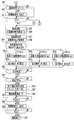
- FIG. 9 is Step 39 of the flowchart showing the operation in the energy saving drying mode in the air conditioner according to Embodiment 1 of the present invention.
- FIG. 10 is a partial view showing steps 41 to 55 and steps 55 to 70.
- FIG. FIG. 11 (a) is a partial view showing steps 42 to 54 of the flowchart showing the operation in the energy-saving drying mode in the air conditioner according to Embodiment 1
- FIG. FIG. 11 (b) is a conceptual diagram showing another display example showing the degree of drying of the object to be dried in the air conditioner according to Embodiment 1 of the present invention.
- FIG. 10 is a partial view showing steps 41 to 55 and steps 55 to 70.
- FIG. FIG. 11 (a) is a partial view showing steps 42 to 54 of the flowchart showing the operation in the energy-saving drying mode in the air conditioner according to Embodiment 1
- FIG. 11 (b) is
- the dehumidifying means 5 In the standard drying mode, the dehumidifying means 5 is operated from the beginning of the operation, whereas in the energy saving drying mode, the dehumidifying means 5 is not operated at the beginning of the operation, and the fan motor 2a as the blowing means is operated to rotate the blowing fan 2. Only the air blowing operation is performed.
- the energy-saving drying mode it is not limited to this expression, and may be an expression representing suppression of power consumption, and may be, for example, a power saving mode or a power saving mode.
- the operation of the control circuit 7 is started by the input of the power switch 9, and the energy saving drying mode is selected from the drying modes of the object to be dried by operating the drying mode switch 11 provided in the operation unit 8. Is detected, the measurement of the total operation time T from the start of operation is started (S0), and the air direction variable means 1 is driven to enable the air to be blown from the exhaust port 103, and the fan motor 2a is driven to rotate the blower fan 2. Then, the blowing operation is started (S1). As described above, the operation of the dehumidifying means 5 is not started at this stage.
- the control circuit 7 operates the infrared sensor 6.
- the surface temperature detection range (full scanning range 200) by the infrared sensor 6 is substantially the same as the direction of the dry air B varied by the vertical direction louver 1a and the horizontal direction louver 1b, and each louver 1a, 1b. Is capable of detecting the surface temperature of the entire region within the air blowable range, and is divided into a plurality of areas (for example, the area of one section is 201) with respect to the entire scanning range 200 of the infrared sensor 6. The temperature is detected (S3 to S4).
- to-be-dried clothes such as wet clothing are evaporated by receiving air, and the surface temperature becomes lower than the ambient temperature.
- the infrared sensor 6 By detecting this low temperature range with the infrared sensor 6, it is detected that an object to be dried is arranged in that range.
- the initial drying degree of the object to be dried is displayed on the display means 12 as the object to be dried display mark 13 (S5), and the initial energy saving level is displayed on the display means 12 as the energy saving level display mark 14 (S6).
- the to-be-dried object display mark 13 displays the display 13a which shows the initial drying degree as a display at the time of starting, as shown to Fig.11 (a). 13a displays all three of the display areas divided into three.
- the shape of the to-be-dried object display mark 13 is not limited to this, What is necessary is just a shape which shows that to-be-dried object is shown, and it can display also with a figure or a character.
- the energy saving level display mark 14 is not limited to this shape as long as it can be understood that the energy saving level can be expressed. If the energy saving level changes during the process, the display changes accordingly. You may make it make it.
- control circuit 7 moves to an operation (S7) for determining the rotational speed of the blower fan 2, and counts the number of divided areas where the object to be dried is arranged ( S8) and the amount of the object to be dried is calculated (S9). If the number of counted areas is large, the amount of the object to be dried is large, and if it is small, it can be determined that the amount of the object to be dried is small.
- the control circuit 7 changes the rotation speed of the blower fan 2 according to the counted number of areas (S10a to S10d), and suppresses power consumption.
- the process of measuring the temperature and humidity of the indoor air A is entered.
- the determination of the initial humidity is performed until a predetermined time elapses (S11 to S12) so that the temperature and humidity can be stably detected. Do not move to.
- the indoor air A is taken into the air conditioner casing 100 from the suction port 101 by the rotation of the blower fan 2 described above for the initial environment determination (S13).
- the control circuit 7 reads the room temperature RT detected by the temperature sensor 3, and reads the room humidity RH1 detected by the humidity sensor 4 (S14).
- the control circuit 7 compares the detected temperature RT of the indoor air A with a predetermined temperature set in advance (S15).
- the predetermined temperature is set to 15 ° C., for example.
- RT is 15 ° C. or lower in S15
- the process proceeds to S71 to start the dehumidifying operation, and when RT is 15 ° C. or higher in S15, the process proceeds to S16. Transition.
- the control circuit 7 compares the detected humidity RH1 of the indoor air A with a predetermined humidity set in advance (S16).
- the predetermined humidity is set to 80%, for example.
- RH1 is 80% or more in S16
- the process proceeds to S71 to start the dehumidifying operation, and when RH1 is 80% or less in S16, the process proceeds to S17. Transition.
- the state of the indoor air A in the state of transition from S16 to S17 is a state in which the humidity is low and the temperature is high, so that it can be said that, for example, a wet object to be dried is relatively easy to dry.
- the process moves directly to the dehumidifying operation without continuing the blowing operation, and the object to be dried is not dried.
- the control is switched to the control for promoting the drying so that the material to be dried can be dried at the end of the operation.
- the control circuit 7 executes control to detect the maximum value RHMax (S17 to S18).
- the control circuit 7 proceeds to S33, and when the maximum humidity value RHMax is not detected, the control circuit 7 proceeds to S22.
- the maximum humidity value RHMax is detected based on whether or not the average humidity RHAve for a predetermined time, eg, 10 minutes, starts to decrease (S19 to S20). When it is detected (S31 to S32), it is determined that the maximum humidity value RHMax has been detected.
- the highest humidity value among the detected humidity values RH1 may be set as the maximum humidity value RHMax, and the humidity value RHMax when the humidity value RH1 changes from rising to falling may be used.
- the maximum value RHMax may be used.
- the process for determining the air blowing operation time is entered from S33, the control circuit 7 determines the maximum value RHMax of the humidity, measures the temperature RT of the indoor air A at that time (S34), and the object to be dried is arranged. The number of divided areas is counted again (S35). A variable H for setting the air blowing operation time is determined from the counted number of areas according to the rotational speed (S36a to S36d).
- This is a process for setting the air blowing operation time according to the rotation speed so that the drying progress is different in the same air blowing operation time when the rotation speed is lowered and the air blowing operation time is the same. is there.
- the control circuit 7 detects the change state of the maximum humidity value RHMax (S37), calculates the remaining blowing operation time Tf (S38), and proceeds to S39.
- the air blowing time Tf is set to be longer as the maximum humidity value RHMax is larger. This makes it possible to shorten the time of the dehumidifying operation which consumes a large amount of power even when the humidity is high, and thus energy saving. The effect can be obtained.
- control circuit 7 proceeds to S55, starts the dehumidifying operation, operates the blower fan 2 and the dehumidifying means 5, starts the measurement of the dehumidifying operation time TJ from the start of the dehumidifying operation (S56), and proceeds to S57. To do.
- control circuit 7 changes the display of the energy saving level display mark 14 on the display means 12 according to the rotation speed change of the blower fan 2, for example, increases or decreases the number of marks as the energy saving level becomes higher.
- the display is also changed (S61a to S61c).
- the energy saving level display mark 14 is displayed by setting the energy saving level of each operation mode in advance when each operation mode is selected, and displaying the energy saving level display mark 14 in accordance with the energy saving level. It is also possible to set a standard for selecting an energy saving operation.
- control circuit 7 determines whether or not the humidity RH1 of the indoor air A has become 50% or less after 10 minutes have passed since the start of the dehumidifying operation (S62) (S63), and the humidity RH1 of the indoor air A is 50%. If it is below, the process proceeds to S64.
- the process proceeds to S64 to enter the step of calculating the end time Y of the dehumidifying operation, and the end time Y is calculated from the dehumidifying operation time TJ from the start of the dehumidifying operation and the room temperature RT (S65), and the process proceeds to S66 and the remaining operating time of the dehumidifying operation TY is measured.
- the drying state of the object to be dried is displayed according to the progress of the operation for drying the object to be dried. Therefore, it is not necessary to move to the place where the object to be dried is placed and touch it to confirm the dry state, so that the convenience of the user can be improved.
- the display area of the object to be dried display mark 13 as shown in FIG. 11A is reduced in accordance with the progress of drying.
- the display method is not limited to this display method.
- the display area may be increased to 13e, 13f, and 13g according to the progress of drying from the state that is not displayed as 13d shown in FIG. The usability can be improved as well.
- the numerical values such as the predetermined time, temperature, and humidity, which are the reference of the control used in the description of the first embodiment, are examples, and are not limited to these numerical values.
- the predetermined numerical values serving as these standards can be appropriately set within a range that does not depart from the scope of the present invention in accordance with the environment in which the air conditioner is used and the user's preference.
- the present invention can be used for an air conditioner that dehumidifies indoor moisture, and in particular, an air conditioner that has a function of drying laundry that is dried to be dried indoors.
- 1 Wind direction varying means 1a Longitudinal louver, 1b Lateral louver, 1c Longitudinal variable motor, 1d Lateral variable motor, 2 Blower fan, 2a Fan motor, 3 Temperature sensor, 4 Humidity sensor, 5 Dehumidifying means, 6 Infrared sensor , 6a Infrared absorbing film, 6b Thermistor, 7 Control circuit, 8 Operation unit, 9 Power switch, 10 Dehumidification mode switch, 11 Drying mode switch, 12 Display means, 13 Drying object display mark, 13a-13g Drying object display mark Display example, 14 energy saving level display mark, 100 air conditioner housing, 101 suction port, 102 water storage tank, 103 exhaust port, 200 full scanning range, 201 divided area, A room air, B dry air.
Abstract
Obtained is an air conditioner that has favorable usability and whereby it is possible to easily confirm the progress of the state of drying of an object to be dried merely by looking at a display. Thus, the present invention is provided with: a dehumidification means (5) that eliminates moisture contained within air; a blower means (2a) that comprises a motor and a blower fan and that sucks in-room air and blows into the room dried air obtained by passing through the dehumidification means (5); a humidity detection means (3) that detects the humidity of in-room air; a temperature detection means (4) that detects the temperature of in-room air; a surface temperature detection means (6) that detects the surface temperature in the room within a predetermined range; a display means (12) that displays information by means of text and/or graphics; and a control means (7) that controls the blower means (2a), the temperature detection means (4), and the display means (12). The control means (7) detects within the predetermined range that an object to be dried such as wet clothing has been disposed from the surface temperature detected by the surface temperature detection means (6), and displays the state of drying of the object to be dried at the display means (12) in accordance with the detection results.
Description
本発明は、室内の湿気を除湿する空気調和機、特に室内に干された被乾燥物である洗濯物を乾燥する機能を有する空気調和機に関するものである。
The present invention relates to an air conditioner that dehumidifies indoor moisture, and more particularly to an air conditioner that has a function of drying laundry that is to be dried in a room.
従来の空気調和機として、赤外線検出手段による温度検出結果と、温度検出手段による室内雰囲気温度検出結果を制御手段が比較することで、被乾燥物の吸収した水分蒸発による顕熱低下を認識し、被乾燥物の顕熱低下による室内温度より低い温度分布の所在を被乾燥物の配置範囲と判断するものがある(例えば、特許文献1参照)。
As a conventional air conditioner, the control means compares the temperature detection result by the infrared detection means and the indoor atmosphere temperature detection result by the temperature detection means, thereby recognizing a decrease in sensible heat due to moisture evaporation absorbed by the object to be dried. There exists a thing which judges the location of temperature distribution lower than the room temperature by the sensible heat fall of a to-be-dried object as the arrangement | positioning range of a to-be-dried object (for example, refer patent document 1).
前述した従来の空気調和機においては、被乾燥物の乾燥状態がどれだけ進んだかという情報を使用者に提供できず、使用者が被乾燥物を触ったりして進み具合を確認しなければならない、という課題があった。
また、使用者が被乾燥物の乾燥運転終了が近いのかどうかを判断することもできない、という課題があった。 In the conventional air conditioner described above, it is impossible to provide the user with information on how much the drying state of the object to be dried has progressed, and the user must check the progress by touching the object to be dried. There was a problem.
Further, there is a problem that the user cannot determine whether the drying operation of the object to be dried is almost finished.
本発明は、前述のような課題を解決するためになされたものであり、使用者は表示を見るだけで被乾燥物の乾燥状態の進み具合を容易に確認できる使い勝手のよい空気調和機を得ることを目的とする。
The present invention has been made to solve the above-described problems, and a user-friendly air conditioner that allows the user to easily confirm the progress of the dry state of the object to be dried by simply looking at the display is obtained. For the purpose.
本発明に係る空気調和機は、空気中に含まれる水分を除去する除湿手段と、室内の空気を吸気し前記除湿手段に通過させて得られた乾燥空気を室内に吹き出す、モーターと送風ファンからなる送風手段と、室内空気の湿度を検出する湿度検出手段と、室内空気の温度を検出する温度検出手段と、所定範囲内で室内の表面温度を検出する表面温度検出手段と、文字または図形の一方または両方で情報を表示する表示手段と、送風手段、温度検出手段、表示手段を制御する制御手段とを備え、制御手段は、表面温度検出手段により検出された表面温度から濡れた衣類等の被乾燥物が配置されていることを所定範囲内において検知し、その検知結果に応じて被乾燥物の乾燥状態を表示手段に表示するものである。
An air conditioner according to the present invention includes a dehumidifying unit that removes moisture contained in the air, and a motor and a blower fan that sucks indoor air and blows dry air obtained by passing the air through the dehumidifying unit. The air blowing means, the humidity detecting means for detecting the humidity of the indoor air, the temperature detecting means for detecting the temperature of the indoor air, the surface temperature detecting means for detecting the indoor surface temperature within a predetermined range, and a character or figure A display means for displaying information on one or both sides, a blower means, a temperature detection means, and a control means for controlling the display means, the control means such as clothing wet from the surface temperature detected by the surface temperature detection means It is detected within a predetermined range that the object to be dried is arranged, and the dry state of the object to be dried is displayed on the display means according to the detection result.
本発明によれば、温度や湿度の検出結果に応じて、表示手段に被乾燥物の乾燥状態を表示するようにしたので、使用者が被乾燥物に触れて確認することなく、表示を見ることにより被乾燥物の乾燥状態の進み具合を容易に確認でき、使い勝手が向上する。
According to the present invention, since the dry state of the object to be dried is displayed on the display means according to the detection result of the temperature and humidity, the display can be viewed without the user touching and confirming the object to be dried. As a result, the progress of the dry state of the object to be dried can be easily confirmed, and the usability is improved.
実施の形態1.
図1は本発明の実施の形態1に係る空気調和機を示す外観斜視図、図2は本発明の実施の形態1に係る空気調和機の表示手段及び操作部を上方からみた上面図、図3は本発明の実施の形態1に係る空気調和機の内部を示す概略構成図、図4は図1の風向変更手段を拡大して示す概略斜視図、図5は本発明の実施の形態1に係る空気調和機の赤外線センサーの検出範囲を示す概念図である。Embodiment 1 FIG.
1 is an external perspective view showing an air conditioner according toEmbodiment 1 of the present invention, and FIG. 2 is a top view of a display unit and an operation unit of the air conditioner according to Embodiment 1 of the present invention as viewed from above. 3 is a schematic configuration diagram showing the inside of the air conditioner according to Embodiment 1 of the present invention, FIG. 4 is an enlarged schematic perspective view showing the wind direction changing means of FIG. 1, and FIG. 5 is Embodiment 1 of the present invention. It is a conceptual diagram which shows the detection range of the infrared sensor of the air conditioner which concerns on.
図1は本発明の実施の形態1に係る空気調和機を示す外観斜視図、図2は本発明の実施の形態1に係る空気調和機の表示手段及び操作部を上方からみた上面図、図3は本発明の実施の形態1に係る空気調和機の内部を示す概略構成図、図4は図1の風向変更手段を拡大して示す概略斜視図、図5は本発明の実施の形態1に係る空気調和機の赤外線センサーの検出範囲を示す概念図である。
1 is an external perspective view showing an air conditioner according to
本発明の実施の形態1の空気調和機は、図1に示すように自立可能に構成された空気調和機筐体100と、空気調和機筐体100内に室内空気Aを取り込むための吸込口101と、吸込口101に取り込まれた空気から除去された水分を溜める貯水タンク102と、水分が除去された乾燥空気Bを空気調和機筐体100から室内へ排出する排気口103とで構成されている。
An air conditioner according to Embodiment 1 of the present invention includes an air conditioner housing 100 configured to be independent as shown in FIG. 1, and a suction port for taking indoor air A into the air conditioner housing 100. 101, a water storage tank 102 for storing moisture removed from the air taken into the suction port 101, and an exhaust port 103 for discharging the dry air B from which moisture has been removed from the air conditioner housing 100 to the room. ing.
排気口103は、乾燥空気Bの風向を可変可能な風向可変手段1が設けられていて、風向可変手段1は、鉛直方向の風向を可変する縦方向ルーバー1aと、水平方向の風向を可変する横方向ルーバー1bとによって構成されている。貯水タンク102は、空気調和機筐体100に着脱可能に取り付けられている。
The exhaust port 103 is provided with a wind direction varying means 1 capable of varying the wind direction of the dry air B. The wind direction varying means 1 varies the vertical direction louver 1a that varies the vertical direction and the horizontal direction. And a lateral louver 1b. The water storage tank 102 is detachably attached to the air conditioner housing 100.
さらに、図2に示すように空気調和機筐体100の上面には操作部8と操作状況や温度、湿度等の各種情報を表示する表示手段12が設けられており、操作部8には例えば電源スイッチ9と除湿モードスイッチ10、乾燥モードスイッチ11が設けられている。
Further, as shown in FIG. 2, an operation unit 8 and display means 12 for displaying various information such as operation status, temperature, and humidity are provided on the upper surface of the air conditioner housing 100. A power switch 9, a dehumidifying mode switch 10, and a drying mode switch 11 are provided.
また、前述の空気調和機には、図3に示すように、吸込口101から室内空気Aを吸い込んで排気口103から乾燥空気Bを排出するという一連の気流を発生させる送風手段を構成する送風ファン2と、送風ファン2を回転させるファンモーター2aと、吸込口101から吸引された室内空気Aの温度を検出する温度センサー3(温度検出手段)と、室内空気Aの湿度を検出する湿度センサー4(湿度検出手段)と、室内空気Aに含まれる水分を除去して乾燥空気Bを生成する除湿手段5が備えられている。
Further, as shown in FIG. 3, the above-described air conditioner includes a blower that constitutes a blower that generates a series of airflows that sucks the indoor air A from the suction port 101 and discharges the dry air B from the exhaust port 103. Fan 2, fan motor 2 a that rotates blower fan 2, temperature sensor 3 (temperature detection means) that detects the temperature of indoor air A sucked from suction port 101, and humidity sensor that detects the humidity of room air A 4 (humidity detecting means) and a dehumidifying means 5 for generating dry air B by removing moisture contained in the room air A.
さらに、風向可変手段1を構成する縦方向ルーバー1aを鉛直方向に可変する縦方向可変モーター1cと、風向可変手段1を構成する横方向ルーバー1bを水平方向に可変する横方向可変モーター1dと、表面温度検出手段である赤外線センサー6と、風向可変手段1を制御する制御手段を内包し、表面温度検出手段である赤外線センサー6などを制御する制御回路7とが備えられている。
Furthermore, a longitudinal variable motor 1c that varies the vertical louver 1a constituting the wind direction varying means 1 in the vertical direction, a lateral variable motor 1d that varies the lateral louver 1b constituting the wind direction varying means 1 in the horizontal direction, An infrared sensor 6 serving as a surface temperature detecting means and a control circuit 7 including a control means for controlling the wind direction varying means 1 and controlling the infrared sensor 6 serving as a surface temperature detecting means are provided.
前述の温度センサー3、湿度センサー4、赤外線センサー6などの各種センサーは、制御回路7で制御され各種データを検出するようになっていて、さらに制御回路7は、それらの検出結果により除湿手段5やファンモーター2a、表示手段12などの駆動を制御している。
Various sensors such as the temperature sensor 3, the humidity sensor 4, and the infrared sensor 6 described above are controlled by the control circuit 7 to detect various data, and the control circuit 7 further determines the dehumidifying means 5 based on the detection results. And drive of the fan motor 2a, the display means 12, and the like are controlled.
除湿手段5は、空気中の水分を除去して凝縮させることができるものであれば良く、例えば、最も一般的なものとして、ヒートポンプ回路を構成し蒸発器において空気中の水分を凝縮させる方式や、吸着剤によって除去された空気中の水分を熱交換器で凝縮させるデシカント方式などが用いられている。除湿手段5によって室内空気Aから除去された水分は、凝縮水Cとして貯水タンク102に貯留される。
The dehumidifying means 5 only needs to be capable of removing moisture in the air and condensing it. For example, as a most general one, a method of constituting a heat pump circuit and condensing moisture in the air in an evaporator, In addition, a desiccant method in which moisture in the air removed by the adsorbent is condensed by a heat exchanger is used. The water removed from the room air A by the dehumidifying means 5 is stored in the water storage tank 102 as condensed water C.
縦方向ルーバー1aは、図4に示すように、空気調和機筐体100の幅方向に延びる長方形状の開口を有し、前述した縦方向可変モーター1cの回転軸をほぼ軸として鉛直方向に可変可能に構成されている。横方向ルーバー1bは、縦方向ルーバー1a内に等間隔に配置され、縦方向ルーバー1aの開口の反対側の奧に水平方向に可変可能に軸支され、前述した横方向可変モーター1dの駆動に連動するように構成されている。
As shown in FIG. 4, the vertical louver 1a has a rectangular opening extending in the width direction of the air conditioner casing 100, and is variable in the vertical direction with the rotational axis of the vertical variable motor 1c described above as a substantial axis. It is configured to be possible. The horizontal louvers 1b are arranged at equal intervals in the vertical louver 1a, and are pivotally supported so as to be variable in the horizontal direction on the side opposite to the opening of the vertical louver 1a. It is configured to work together.
赤外線センサー6は、縦方向ルーバー1a内に配置されたほぼ中央の横方向ルーバー1bの片面に取り付けられている。これにより、赤外線センサー6による表面温度の検出範囲は、風向可変手段1によって可変される乾燥空気Bの方向とほぼ同一となる。
The infrared sensor 6 is attached to one side of a substantially central lateral louver 1b disposed in the longitudinal louver 1a. Thereby, the detection range of the surface temperature by the infrared sensor 6 becomes substantially the same as the direction of the dry air B which is varied by the air direction varying means 1.
つまり、赤外線センサー6は、風向可変手段1が送風可能な範囲内の全領域にある物体、例えば洗濯後の濡れた衣類やタオル等(以下、これらを総称して「被乾燥物」という)の表面温度を検出することができる。
In other words, the infrared sensor 6 is used for objects in all areas within the range in which the wind direction changing means 1 can blow air, such as wet clothes and towels after washing (hereinafter collectively referred to as “objects to be dried”). The surface temperature can be detected.
前述の赤外線センサー6は、例えば熱起電力効果を利用したものが用いられており、所定領域の表面から発せられる熱放射(赤外線)を受ける赤外線吸収膜6aと、赤外線吸収膜6aの温度を検出するサーミスタ6bとで構成されている(図3、図4参照)。
The above-described infrared sensor 6 uses, for example, a thermoelectromotive force effect, and detects the temperature of the infrared absorption film 6a that receives thermal radiation (infrared rays) emitted from the surface of a predetermined region, and the temperature of the infrared absorption film 6a. And the thermistor 6b (see FIGS. 3 and 4).
この赤外線センサー6は、熱放射を吸収することによって昇温する赤外線吸収膜6aの感熱部分の温度(温接点)と、サーミスタ6bによって検出される赤外線吸収膜6aの温度(冷接点)との差を電圧等の電気信号に変換し、制御回路7に入力する。この電気信号の大きさから所定領域の表面温度を検出できる。
The infrared sensor 6 has a difference between the temperature of the heat-sensitive part of the infrared absorption film 6a that rises in temperature by absorbing thermal radiation (hot contact) and the temperature of the infrared absorption film 6a detected by the thermistor 6b (cold contact). Is converted into an electrical signal such as a voltage and input to the control circuit 7. The surface temperature of a predetermined region can be detected from the magnitude of this electrical signal.
ここで、所定領域の表面温度の検出方法について図5を用いて説明する。
図5に示すように、赤外線センサー6が検出可能な全領域を全走査範囲200とした場合、全走査範囲200は、横方向(水平方向)、縦方向(鉛直方向)に拡がる面状の範囲となる。 Here, a method for detecting the surface temperature of the predetermined region will be described with reference to FIG.
As shown in FIG. 5, when the entire area that can be detected by theinfrared sensor 6 is the entire scanning range 200, the entire scanning range 200 is a planar area that extends in the horizontal direction (horizontal direction) and the vertical direction (vertical direction). It becomes.
図5に示すように、赤外線センサー6が検出可能な全領域を全走査範囲200とした場合、全走査範囲200は、横方向(水平方向)、縦方向(鉛直方向)に拡がる面状の範囲となる。 Here, a method for detecting the surface temperature of the predetermined region will be described with reference to FIG.
As shown in FIG. 5, when the entire area that can be detected by the
この赤外線センサー6は、全走査範囲200を水平方向と鉛直方向に対して、複数に分割る。これにより、広範囲の領域に対して詳細な温度マップを作成することができる。
This infrared sensor 6 divides the entire scanning range 200 into a plurality of horizontal and vertical directions. Thereby, a detailed temperature map can be created for a wide range of regions.
制御回路7は、図2に示す電源スイッチ9の入力により動作が開始され、操作部8に設けられた除湿モードスイッチ10を操作することにより、除湿モードが選択されたことを検知すると、室内の湿度が最適湿度となるように風向可変手段1を駆動して排気口103から送風可能にし、ファンモーター2aを駆動して送風ファン2を回転させ、除湿手段5を駆動する。
When the control circuit 7 starts operating by the input of the power switch 9 shown in FIG. 2 and operates the dehumidifying mode switch 10 provided in the operation unit 8 to detect that the dehumidifying mode is selected, The wind direction varying means 1 is driven so that the humidity becomes the optimum humidity so that air can be blown from the exhaust port 103, the fan motor 2a is driven to rotate the blower fan 2, and the dehumidifying means 5 is driven.
また、制御回路7は、室内の所望領域の方向に送風されるように、風向可変手段1の縦方向可変モーター1cと横方向可変モーター1dを駆動する。これにより、室内空気Aは、吸込口101から空気調和機筐体100内に取り込まれ、温度センサー3及び湿度センサー4によりそれぞれ室内の温度と湿度が検出された後、除湿手段5により除湿されて乾燥空気Bとなり、排気口103から室内に吹き出される。
Further, the control circuit 7 drives the vertical direction variable motor 1c and the horizontal direction variable motor 1d of the wind direction varying means 1 so that the air is blown in the direction of a desired area in the room. As a result, the indoor air A is taken into the air conditioner casing 100 from the suction port 101, and the indoor temperature and humidity are detected by the temperature sensor 3 and the humidity sensor 4, respectively, and then dehumidified by the dehumidifying means 5. It becomes dry air B and is blown out into the room from the exhaust port 103.
さらに制御回路7は、図2に示す電源スイッチ9の入力により動作が開始され、操作部8に設けられた乾燥モードスイッチ11を操作することにより、例えば衣類等の洗濯物に代表される被乾燥物の乾燥モードの中から標準乾燥モードが選択されたことを検知すると、風向可変手段1を駆動して排気口103から送風可能にし、ファンモーター2aを駆動して送風ファン2を回転させ、除湿手段5を駆動する。
Further, the operation of the control circuit 7 is started by an input of the power switch 9 shown in FIG. 2, and by operating a drying mode switch 11 provided in the operation unit 8, for example, to-be-dried typified by laundry such as clothes. When it is detected that the standard drying mode has been selected from among the drying modes of the objects, the air direction varying means 1 is driven to allow air to be blown from the exhaust port 103, the fan motor 2a is driven to rotate the blower fan 2, and dehumidification The means 5 is driven.
その後、制御回路7は、空気調和機筐体100内に取り込まれた室内空気Aから、室内の湿度を湿度センサー4を介して読み込み、その湿度があらかじめ設定された所定の湿度より高いかどうかを判定する。
Thereafter, the control circuit 7 reads the indoor humidity from the indoor air A taken into the air conditioner casing 100 via the humidity sensor 4 and determines whether the humidity is higher than a predetermined humidity. judge.
ここで所定の湿度とは、温度センサー3によって検出される室内の温度に対応してあらかじめ設定されている数値データのことであり、数値データとして制御回路7に内包された図示しない記憶手段に収容されていて、必要に応じて制御回路7に読み出されるようになっている。
Here, the predetermined humidity is numerical data set in advance corresponding to the indoor temperature detected by the temperature sensor 3, and is stored as numerical data in a storage means (not shown) included in the control circuit 7. It is read by the control circuit 7 as required.
湿度判定の結果、室内の湿度が所定の湿度より高いときには、室内の湿度が所定の湿度と同じ値以下に低下するまで除湿手段5の除湿能力が最大となるようにファンモーター2a及び風向可変手段1を制御する。
As a result of the humidity determination, when the indoor humidity is higher than the predetermined humidity, the fan motor 2a and the wind direction varying means are set so that the dehumidifying means 5 has the maximum dehumidifying capacity until the indoor humidity is reduced to the same value or less as the predetermined humidity. 1 is controlled.
制御回路7は、前述の制御によって室内の湿度が所定の湿度と同じ値以下まで低下したときには、赤外線センサー6を用いて前述の複数に分割されたエリア(201)毎に表面温度を検出し、表面温度の検出結果から被乾燥物が配置されている範囲を特定し、その範囲に乾燥空気Bが当たるように縦方向可変モーター1cと横方向可変モーター1dを制御し、各ルーバー1a、1bを被乾燥物の方向に向ける。
The control circuit 7 detects the surface temperature for each of the plurality of divided areas (201) using the infrared sensor 6 when the indoor humidity is reduced to the same value or less as the predetermined humidity by the control described above. The range in which the object to be dried is located is specified from the detection result of the surface temperature, and the vertical direction variable motor 1c and the horizontal direction variable motor 1d are controlled so that the dry air B hits the range, and each louver 1a, 1b is controlled. Direct toward the material to be dried.
次に、乾燥モードの中から消費電力を抑制しながら被乾燥物を乾燥させる省エネ乾燥モードが選択されたときの動作について図6から図11を用いて説明する。
図6は本発明の実施の形態1に係る空気調和機における省エネ乾燥モードのときの動作を示すフローチャートのステップ0からステップ18及びステップ71を示す部分図、図7は本発明の実施の形態1に係る空気調和機における省エネ乾燥モードのときの動作を示すフローチャートのステップ19、ステップ20及びステップS31からステップ38を示す部分図、図8は本発明の実施の形態1に係る空気調和機における省エネ乾燥モードのときの動作を示すフローチャートのステップ21からステップ30を示す部分図、図9は、本発明の実施の形態1に係る空気調和機における省エネ乾燥モードのときの動作を示すフローチャートのステップ39からステップ41及びステップ55からステップ70を示す部分図、図10は本発明の実施の形態1に係る空気調和機における省エネ乾燥モードのときの動作を示すフローチャートのステップ42からステップ54を示す部分図、図11(a)は本発明の実施の形態1に係る空気調和機における被乾燥物の乾燥度合いを表す1つの表示例を示す概念図、図11(b)は本発明の実施の形態1に係る空気調和機における被乾燥物の乾燥度合いを表す他の表示例を示す概念図である。 Next, an operation when an energy saving drying mode for drying an object to be dried while suppressing power consumption is selected from the drying modes will be described with reference to FIGS. 6 to 11.
FIG. 6 is a partial view showing steps 0 to 18 and 71 of the flowchart showing the operation in the energy saving drying mode in the air conditioner according toEmbodiment 1 of the present invention, and FIG. 7 is Embodiment 1 of the present invention. FIG. 8 is a partial view showing Step 19, Step 20 and Step S31 to Step 38 of the flowchart showing the operation in the energy saving drying mode in the air conditioner according to FIG. 8, and FIG. 8 shows energy saving in the air conditioner according to Embodiment 1 of the present invention. FIG. 9 is a partial view showing Step 21 to Step 30 of the flowchart showing the operation in the drying mode, and FIG. 9 is Step 39 of the flowchart showing the operation in the energy saving drying mode in the air conditioner according to Embodiment 1 of the present invention. FIG. 10 is a partial view showing steps 41 to 55 and steps 55 to 70. FIG. FIG. 11 (a) is a partial view showing steps 42 to 54 of the flowchart showing the operation in the energy-saving drying mode in the air conditioner according to Embodiment 1, and FIG. FIG. 11 (b) is a conceptual diagram showing another display example showing the degree of drying of the object to be dried in the air conditioner according to Embodiment 1 of the present invention. FIG.
図6は本発明の実施の形態1に係る空気調和機における省エネ乾燥モードのときの動作を示すフローチャートのステップ0からステップ18及びステップ71を示す部分図、図7は本発明の実施の形態1に係る空気調和機における省エネ乾燥モードのときの動作を示すフローチャートのステップ19、ステップ20及びステップS31からステップ38を示す部分図、図8は本発明の実施の形態1に係る空気調和機における省エネ乾燥モードのときの動作を示すフローチャートのステップ21からステップ30を示す部分図、図9は、本発明の実施の形態1に係る空気調和機における省エネ乾燥モードのときの動作を示すフローチャートのステップ39からステップ41及びステップ55からステップ70を示す部分図、図10は本発明の実施の形態1に係る空気調和機における省エネ乾燥モードのときの動作を示すフローチャートのステップ42からステップ54を示す部分図、図11(a)は本発明の実施の形態1に係る空気調和機における被乾燥物の乾燥度合いを表す1つの表示例を示す概念図、図11(b)は本発明の実施の形態1に係る空気調和機における被乾燥物の乾燥度合いを表す他の表示例を示す概念図である。 Next, an operation when an energy saving drying mode for drying an object to be dried while suppressing power consumption is selected from the drying modes will be described with reference to FIGS. 6 to 11.
FIG. 6 is a partial view showing steps 0 to 18 and 71 of the flowchart showing the operation in the energy saving drying mode in the air conditioner according to
標準乾燥モードが運転開始当初から除湿手段5を動作させるのに対し、省エネ乾燥モードは運転開始当初除湿手段5を動作させず、送風手段であるファンモーター2aを動作させ送風ファン2を回転させて送風運転のみ行うようになっている。
なお、ここでは省エネ乾燥モードとしているがこの表現に限定されるものではなく、消費電力を抑制することを表す表現であればよいので、例えば節電モードや省電力モードとしてもよい。 In the standard drying mode, the dehumidifying means 5 is operated from the beginning of the operation, whereas in the energy saving drying mode, the dehumidifying means 5 is not operated at the beginning of the operation, and thefan motor 2a as the blowing means is operated to rotate the blowing fan 2. Only the air blowing operation is performed.
In addition, although it is set as the energy-saving drying mode here, it is not limited to this expression, and may be an expression representing suppression of power consumption, and may be, for example, a power saving mode or a power saving mode.
なお、ここでは省エネ乾燥モードとしているがこの表現に限定されるものではなく、消費電力を抑制することを表す表現であればよいので、例えば節電モードや省電力モードとしてもよい。 In the standard drying mode, the dehumidifying means 5 is operated from the beginning of the operation, whereas in the energy saving drying mode, the dehumidifying means 5 is not operated at the beginning of the operation, and the
In addition, although it is set as the energy-saving drying mode here, it is not limited to this expression, and may be an expression representing suppression of power consumption, and may be, for example, a power saving mode or a power saving mode.
制御回路7は、電源スイッチ9の入力により動作が開始され、操作部8に設けられた乾燥モードスイッチ11を操作することにより、被乾燥物の乾燥モードの中から省エネ乾燥モードが選択されたことを検知すると、運転開始からの総運転時間Tの測定を開始する(S0)と共に、風向可変手段1を駆動して排気口103から送風可能にし、ファンモーター2aを駆動して送風ファン2を回転させて送風運転を開始する(S1)。前述の通り、この段階では除湿手段5の運転は開始されていない。
The operation of the control circuit 7 is started by the input of the power switch 9, and the energy saving drying mode is selected from the drying modes of the object to be dried by operating the drying mode switch 11 provided in the operation unit 8. Is detected, the measurement of the total operation time T from the start of operation is started (S0), and the air direction variable means 1 is driven to enable the air to be blown from the exhaust port 103, and the fan motor 2a is driven to rotate the blower fan 2. Then, the blowing operation is started (S1). As described above, the operation of the dehumidifying means 5 is not started at this stage.
送風運転の開始にあわせ、被乾燥物の配置を検知するための準備に入り、縦方向可変モーター1cと横方向可変モーター1dを制御し、各ルーバー1a、1bを可動し送風方向を調整する(S2)。
Along with the start of the air blowing operation, preparations for detecting the arrangement of the object to be dried are entered, the longitudinal variable motor 1c and the lateral variable motor 1d are controlled, and the louvers 1a and 1b are moved to adjust the air blowing direction ( S2).
その後、制御回路7は赤外線センサー6を作動する。赤外線センサー6による表面温度の検出範囲(全走査範囲200)は、前述したように、縦方向ルーバー1aと横方向ルーバー1bによって可変される乾燥空気Bの方向とほぼ同一で、各ルーバー1a、1bが送風可能な範囲内の全領域の表面温度を検出できるようになっていて、赤外線センサー6の全走査範囲200に対して複数に分割されたエリア(例えば一区画のエリアが201)毎の表面温度を検出する(S3~S4)。
Thereafter, the control circuit 7 operates the infrared sensor 6. As described above, the surface temperature detection range (full scanning range 200) by the infrared sensor 6 is substantially the same as the direction of the dry air B varied by the vertical direction louver 1a and the horizontal direction louver 1b, and each louver 1a, 1b. Is capable of detecting the surface temperature of the entire region within the air blowable range, and is divided into a plurality of areas (for example, the area of one section is 201) with respect to the entire scanning range 200 of the infrared sensor 6. The temperature is detected (S3 to S4).
例えば濡れた衣類のような被乾燥物は、送風を受けることにより水分が気化し表面温度が周囲の温度より低くなる。この低くなった温度の範囲を赤外線センサー6で検知することにより、その範囲に被乾燥物が配置されていることを検知している。
For example, to-be-dried clothes such as wet clothing are evaporated by receiving air, and the surface temperature becomes lower than the ambient temperature. By detecting this low temperature range with the infrared sensor 6, it is detected that an object to be dried is arranged in that range.
被乾燥物の初期の乾燥度合いが、表示手段12に被乾燥物表示マーク13として表示(S5)され、初期の省エネレベルが表示手段12に省エネレベル表示マーク14として表示(S6)される。
The initial drying degree of the object to be dried is displayed on the display means 12 as the object to be dried display mark 13 (S5), and the initial energy saving level is displayed on the display means 12 as the energy saving level display mark 14 (S6).
被乾燥物表示マーク13は図11(a)に示すように、スタート時の表示として初期の乾燥度合いを示す表示13aを表示する。13aは3つに分割された表示領域の3つ全てを表示している。なお、被乾燥物表示マーク13の形状はこれに限定されるものではなく、被乾燥物を示すことが分かる形状であればよく、図形または文字によっても表示可能である。
The to-be-dried object display mark 13 displays the display 13a which shows the initial drying degree as a display at the time of starting, as shown to Fig.11 (a). 13a displays all three of the display areas divided into three. In addition, the shape of the to-be-dried object display mark 13 is not limited to this, What is necessary is just a shape which shows that to-be-dried object is shown, and it can display also with a figure or a character.
省エネレベル表示マーク14も同様この形状に、限定されるものではなく、省エネレベルを表すことが分かる形状であればよく、工程の途中で省エネレベルが変わるような場合にはそれに応じて表示を変化させるようにしてもよい。
The energy saving level display mark 14 is not limited to this shape as long as it can be understood that the energy saving level can be expressed. If the energy saving level changes during the process, the display changes accordingly. You may make it make it.
制御回路7は被乾燥物の位置が検出できた段階で、送風ファン2の回転数を決定するための動作(S7)に移り、被乾燥物が配置されている分割されたエリア数をカウント(S8)し、被乾燥物の量を算出する(S9)。カウントされたエリア数が多ければ被乾燥物の量が多く、少なければ被乾燥物の量は少ないと判断できる。
When the position of the object to be dried is detected, the control circuit 7 moves to an operation (S7) for determining the rotational speed of the blower fan 2, and counts the number of divided areas where the object to be dried is arranged ( S8) and the amount of the object to be dried is calculated (S9). If the number of counted areas is large, the amount of the object to be dried is large, and if it is small, it can be determined that the amount of the object to be dried is small.
制御回路7は、カウントされたエリア数に応じて送風ファン2の回転数を変化(S10a~S10d)させ、消費電力の抑制を行う。送風ファン2の回転数は、例えば検出可能な範囲の全分割エリア数をX1、被乾燥物が配置されているとしてカウントされた分割エリア数をX2、最大風量をQ、あらかじめ用意された補正係数m及びnから、被乾燥物に必要な風量、F=m×(X1/X2)×Q+nの式により算出された風量Fを満足する送風量を発生する回転数として設定される。
The control circuit 7 changes the rotation speed of the blower fan 2 according to the counted number of areas (S10a to S10d), and suppresses power consumption. The number of rotations of the blower fan 2 is, for example, X1 as the total number of divided areas in the detectable range, X2 as the number of divided areas counted as objects to be dried, Q as the maximum air volume, and a correction coefficient prepared in advance. From m and n, it is set as the number of revolutions that generates an air volume that satisfies the air volume F calculated by the formula: F = m × (X1 / X2) × Q + n.
次に、室内空気Aの温度と湿度を測定する工程に入るが、温度と湿度を安定的に検出できるように、あらかじめ設定された所定の時間が経過(S11~S12)するまで初期湿度の判定に移行しない。
Next, the process of measuring the temperature and humidity of the indoor air A is entered. The determination of the initial humidity is performed until a predetermined time elapses (S11 to S12) so that the temperature and humidity can be stably detected. Do not move to.
例えば10分で設定された所定の時間が経過した後、初期環境判定(S13)のため、前述の送風ファン2の回転により室内空気Aが吸込口101から空気調和機筐体100内に取り込まれ、この時に制御回路7は、温度センサー3により検出された室内の温度RTを読み込み、湿度センサー4により検出された室内の湿度RH1を読み込む(S14)。
For example, after a predetermined time set in 10 minutes elapses, the indoor air A is taken into the air conditioner casing 100 from the suction port 101 by the rotation of the blower fan 2 described above for the initial environment determination (S13). At this time, the control circuit 7 reads the room temperature RT detected by the temperature sensor 3, and reads the room humidity RH1 detected by the humidity sensor 4 (S14).
次に制御回路7は、検知した室内空気Aの温度RTとあらかじめ設定されている所定の温度と比較する(S15)。所定の温度は、例えば15℃に設定されていて、S15でRTが15℃以下のときはS71に移行して除湿運転を開始するようになり、S15でRTが15℃以上のときはS16へ移行する。
Next, the control circuit 7 compares the detected temperature RT of the indoor air A with a predetermined temperature set in advance (S15). The predetermined temperature is set to 15 ° C., for example. When RT is 15 ° C. or lower in S15, the process proceeds to S71 to start the dehumidifying operation, and when RT is 15 ° C. or higher in S15, the process proceeds to S16. Transition.
S16へ移行すると制御回路7は、検知した室内空気Aの湿度RH1とあらかじめ設定されている所定の湿度と比較する(S16)。所定の湿度は、例えば80%に設定されていて、S16でRH1が80%以上のときはS71に移行して除湿運転を開始するようになり、S16でRH1が80%以下のときはS17へ移行する。
When the process proceeds to S16, the control circuit 7 compares the detected humidity RH1 of the indoor air A with a predetermined humidity set in advance (S16). The predetermined humidity is set to 80%, for example. When RH1 is 80% or more in S16, the process proceeds to S71 to start the dehumidifying operation, and when RH1 is 80% or less in S16, the process proceeds to S17. Transition.
このS16からS17に移行する状況における室内空気Aの状態は、湿度が低くかつ温度が高い状態であるので、例えば濡れているような被乾燥物が比較的乾燥しやすい状態であるといえる。
The state of the indoor air A in the state of transition from S16 to S17 is a state in which the humidity is low and the temperature is high, so that it can be said that, for example, a wet object to be dried is relatively easy to dry.
また、S15及びS16においてS71に移行する状況における室内空気Aの状態は、送風では十分に乾燥できない状態であるので、送風運転を継続せず直接除湿運転に移行し、被乾燥物が未乾燥とならないよう乾燥を促進する制御に切り換え、運転終了時には被乾燥物を乾燥させることができるようにしている。
In addition, since the state of the room air A in the situation where the process proceeds to S71 in S15 and S16 is a state where the air cannot be sufficiently dried by blowing, the process moves directly to the dehumidifying operation without continuing the blowing operation, and the object to be dried is not dried. The control is switched to the control for promoting the drying so that the material to be dried can be dried at the end of the operation.
次に制御回路7は、湿度RH1が所定湿度より低く、かつ、温度RTが所定温度より高い場合は、湿度の最大値RHMaxを検出する制御を実行する(S17~S18)。そして制御回路7は、湿度の最大値RHMaxを検出した場合はS33へ移行し、湿度の最大値RHMaxを検出していない場合はS22に移行する。
Next, when the humidity RH1 is lower than the predetermined humidity and the temperature RT is higher than the predetermined temperature, the control circuit 7 executes control to detect the maximum value RHMax (S17 to S18). When the maximum humidity value RHMax is detected, the control circuit 7 proceeds to S33, and when the maximum humidity value RHMax is not detected, the control circuit 7 proceeds to S22.
湿度の最大値RHMaxの検出は、あらかじめ設定された所定の時間、例えば10分間の平均湿度RHAveが下降しはじめた否かで検知(S19~S20)していて、その下降状態が2回連続して検知(S31~S32)されると湿度の最大値RHMaxを検出したと判断している。
The maximum humidity value RHMax is detected based on whether or not the average humidity RHAve for a predetermined time, eg, 10 minutes, starts to decrease (S19 to S20). When it is detected (S31 to S32), it is determined that the maximum humidity value RHMax has been detected.
なお、湿度の最大値RHMaxの検出方法としては、検知した湿度RH1の内、最も大きい湿度を湿度の最大値RHMaxとしてもよく、また、湿度RH1が上昇から下降に転じたときの湿度RHMaxを湿度の最大値RHMaxとしてもよい。
As a method for detecting the maximum humidity value RHMax, the highest humidity value among the detected humidity values RH1 may be set as the maximum humidity value RHMax, and the humidity value RHMax when the humidity value RH1 changes from rising to falling may be used. The maximum value RHMax may be used.
S22に移行した場合は、湿度の最大値RHMaxが検出できるまで温度や湿度を測定しながら室内空気Aの状態を確認(S22~S30)し送風運転を継続する。但し、その過程で制御回路7が送風運転を継続せず直接除湿運転に移行した方が良いと判断(S24、S25)するとS71に移行して除湿運転を開始する。
When the process proceeds to S22, the state of the indoor air A is confirmed while measuring the temperature and humidity until the maximum humidity value RHMax can be detected (S22 to S30), and the air blowing operation is continued. However, if the control circuit 7 determines that it is better to shift directly to the dehumidifying operation without continuing the blowing operation in the process (S24, S25), the process proceeds to S71 and the dehumidifying operation is started.
次に、S33から送風運転時間を決定する工程に入り、制御回路7は湿度の最大値RHMaxを確定し、その時の室内空気Aの温度RTを測定(S34)、被乾燥物が配置されている分割されたエリア数を再度カウント(S35)する。このカウントされたエリア数から回転数に応じて送風運転時間を設定するための変数Hを決定(S36a~S36d)する。
Next, the process for determining the air blowing operation time is entered from S33, the control circuit 7 determines the maximum value RHMax of the humidity, measures the temperature RT of the indoor air A at that time (S34), and the object to be dried is arranged. The number of divided areas is counted again (S35). A variable H for setting the air blowing operation time is determined from the counted number of areas according to the rotational speed (S36a to S36d).
変数Hは、S35でカウントされたエリア数から設定され、例えば検出されたエリア数が全分割エリア数の3/4以上であればH=1.0、2/4(1/2)以上であればH=1.1というようにカウントされたエリア数が多いほど変数Hの値を小さくなるように設定される。
これは、回転数を下げて送風運転した場合に同じ送風運転時間では乾燥の進行具合が異なるため、乾燥状態に不具合が生じないよう、回転数に応じて送風運転時間を設定するための工程である。 The variable H is set from the number of areas counted in S35. For example, if the number of detected areas is 3/4 or more of the total number of divided areas, H = 1.0, 2/4 (1/2) or more. If so, the value of the variable H is set to be smaller as the number of counted areas is larger, such as H = 1.1.
This is a process for setting the air blowing operation time according to the rotation speed so that the drying progress is different in the same air blowing operation time when the rotation speed is lowered and the air blowing operation time is the same. is there.
次に制御回路7は、湿度の最大値RHMaxの変化状態を検知(S37)して残りの送風運転時間Tfの計算を行い(S38)、S39に移行する。ここで送風時間Tfは、湿度の最大値RHMaxが大きいほど長く設定されるようになっていて、これにより、湿度が高くても電力消費の大きい除湿運転の時間を短くすることができ、より省エネ効果を得られるようになっている。
Next, the control circuit 7 detects the change state of the maximum humidity value RHMax (S37), calculates the remaining blowing operation time Tf (S38), and proceeds to S39. Here, the air blowing time Tf is set to be longer as the maximum humidity value RHMax is larger. This makes it possible to shorten the time of the dehumidifying operation which consumes a large amount of power even when the humidity is high, and thus energy saving. The effect can be obtained.
その後、S38で計算されたTfの1/2以上送風時間が経過(S39)していたら、被乾燥物の乾燥度合いが進んだとして、図11(a)に示す13bのように3つの表示の内、1つを消した2つの点灯状態の表示に変更する(S40)。そして残りの送風運転時間が終了するまで送風運転(S41)を継続した後、除湿運転(S55)へ移行する。
After that, if the blowing time of 1/2 or more of Tf calculated in S38 has elapsed (S39), it is determined that the degree of drying of the object to be dried has progressed, and three displays are displayed as shown in 13b in FIG. 11 (a). Among them, the display is changed to the display of two lighting states in which one is turned off (S40). Then, after continuing the air blowing operation (S41) until the remaining air blowing operation time ends, the process proceeds to the dehumidifying operation (S55).
なお、S41で残りの送風運転時間が終了するまで送風運転を続けることにより、湿度が高い状態に保たれ、住空間に湿害を発生させる可能性がある。これを回避するため、前述の送風運転時間には、最大500分の上限時間が設定されている。
It should be noted that by continuing the air blowing operation until the remaining air blowing operation time ends in S41, the humidity is kept high, and there is a possibility of causing moisture damage in the living space. In order to avoid this, an upper limit time of 500 minutes at the maximum is set for the above-described air blowing operation time.
送風運転時間中において、湿度が高くなるほど湿害が発生しやすくなるため、湿度に応じて送風運転時間を短縮することが必要となり、湿度が高くなるほど送風運転時間を短縮するために湿度を細かく測定(S42~S50)し、送風を行っている間、カウントされたエリア数から送風ファン2の回転数を変化させる制御を続けて行っている(S54a~S54d)。
During the air blowing operation time, moisture damage is more likely to occur as the humidity increases, so it is necessary to shorten the air operation time according to the humidity, and the humidity is measured in detail to shorten the air operation time as the humidity increases. (S42 to S50) During the air blowing, the control for changing the rotation speed of the blower fan 2 from the counted number of areas is continued (S54a to S54d).
次に、制御回路7はS55に移行し除湿運転を開始して送風ファン2と除湿手段5を動作させ、除湿運転開始からの除湿運転時間TJの計測を開始(S56)して、S57に移行する。
Next, the control circuit 7 proceeds to S55, starts the dehumidifying operation, operates the blower fan 2 and the dehumidifying means 5, starts the measurement of the dehumidifying operation time TJ from the start of the dehumidifying operation (S56), and proceeds to S57. To do.
送風ファン2の回転数を決定するための動作(S57)に移り、被乾燥物が配置されている分割されたエリア数をカウント(S58)し、被乾燥物の量を算出する(S59)。制御回路7は、カウントされたエリア数に応じて送風ファン2の回転数を変化(S60a~S60c)させ、消費電力の抑制を行う。
It moves to the operation | movement (S57) for determining the rotation speed of the ventilation fan 2, counts the number of the divided areas where the to-be-dried object is arrange | positioned (S58), and calculates the quantity of to-be-dried object (S59). The control circuit 7 changes the rotational speed of the blower fan 2 according to the counted number of areas (S60a to S60c), and suppresses power consumption.
送風ファン2の回転数は、送風運転のときと同様、検出可能な範囲の全分割エリア数をX1、被乾燥物が配置されているとしてカウントされた分割エリア数をX2、最大風量をQ、あらかじめ用意された補正係数m及びnから、被乾燥物に必要な風量、F=m×(X1/X2)×Q+nの式により算出された風量Fを満足する送風量を発生する回転数として設定される。
The number of rotations of the blower fan 2 is X1, the total number of divided areas in the detectable range, X2, the number of divided areas counted as the objects to be dried are arranged, X, From the correction factors m and n prepared in advance, set as the number of rotations that generates the air volume necessary for the material to be dried, the air volume that satisfies the air volume F calculated by the formula F = m × (X1 / X2) × Q + n Is done.
それから、制御回路7は送風ファン2の回転数変化に応じて、表示手段12に省エネレベル表示マーク14の表示を変化、例えば、省エネレベルが高くなるにつれてマークの数を増やす、または減らすというように表示も変化させる(S61a~S61c)。
Then, the control circuit 7 changes the display of the energy saving level display mark 14 on the display means 12 according to the rotation speed change of the blower fan 2, for example, increases or decreases the number of marks as the energy saving level becomes higher. The display is also changed (S61a to S61c).
なお、省エネレベル表示マーク14の表示は、各運転モードの選択時にあらかじめ各運転モードの省エネレベルを設定しておき、省エネレベルに応じて省エネレベル表示マーク14を増減して表示することでユーザーが省エネ運転を選択する際の基準とすることも可能である。
The energy saving level display mark 14 is displayed by setting the energy saving level of each operation mode in advance when each operation mode is selected, and displaying the energy saving level display mark 14 in accordance with the energy saving level. It is also possible to set a standard for selecting an energy saving operation.
次に制御回路7は、除湿運転開始から10分経過(S62)した後室内空気Aの湿度RH1が50%以下になったか否かを判定(S63)し、室内空気Aの湿度RH1が50%以下になっていたらS64に移行する。
Next, the control circuit 7 determines whether or not the humidity RH1 of the indoor air A has become 50% or less after 10 minutes have passed since the start of the dehumidifying operation (S62) (S63), and the humidity RH1 of the indoor air A is 50%. If it is below, the process proceeds to S64.
S64に移行し除湿運転の終了時間Yを算出する工程に入り、終了時間Yを除湿運転開始からの除湿運転時間TJと室温RTより算出(S65)、S66に移行し除湿運転の残りの運転時間TYを計測する。
The process proceeds to S64 to enter the step of calculating the end time Y of the dehumidifying operation, and the end time Y is calculated from the dehumidifying operation time TJ from the start of the dehumidifying operation and the room temperature RT (S65), and the process proceeds to S66 and the remaining operating time of the dehumidifying operation TY is measured.
除湿運転の残りの運転時間TYが除湿運転の終了時間Yの1/2以上(S67)になったら、被乾燥物の乾燥度合いが終了に近づいたとして、図11(a)に示す13cのように3つの表示の内、2つを消した1つの点灯状態の表示に変更する(S68)。これにより乾燥が進んで終了が近いことを使用者に知らせることができる。
When the remaining operation time TY of the dehumidifying operation becomes ½ or more of the end time Y of the dehumidifying operation (S67), it is determined that the degree of drying of the object to be dried is close to the end as shown in 13c in FIG. Of these three displays, the display is changed to one lighting state display in which two are turned off (S68). As a result, the user can be informed that the drying is progressing and the end is near.
そして、運転を継続し除湿運転の残りの運転時間TYが除湿運転の終了時間Y以上(S69)となったらS70へ移行し運転を終了、省エネ乾燥モードの運転が完了する。
Then, the operation is continued, and when the remaining operation time TY of the dehumidifying operation becomes equal to or longer than the end time Y of the dehumidifying operation (S69), the process proceeds to S70, the operation is ended, and the operation in the energy saving drying mode is completed.
以上のように本発明の実施の形態1によれば、被乾燥物を乾燥させる運転の進行に応じて被乾燥物の乾燥状態を表示するようにしたので、使用者が被乾燥物の乾燥状態を容易に確認できるので、いちいち被乾燥物の置いてある場所まで移動し、触って乾燥状態を確認する必要がなく使用者の利便性を向上させることができる。
As described above, according to the first embodiment of the present invention, the drying state of the object to be dried is displayed according to the progress of the operation for drying the object to be dried. Therefore, it is not necessary to move to the place where the object to be dried is placed and touch it to confirm the dry state, so that the convenience of the user can be improved.
なお、本実施の形態1では図11(a)に示したような被乾燥物表示マーク13を乾燥の進捗にあわせ表示領域を減らしていくようにしたが、この表示方法に限定されるものではなく、図11(b)に示す13dのように表示されていない状態から被乾燥物表示マーク13を乾燥の進捗にあわせ13e、13f、13gと表示領域を増加させていってもよく、使用者の使い勝手を同様に向上させることができる。
In the first embodiment, the display area of the object to be dried display mark 13 as shown in FIG. 11A is reduced in accordance with the progress of drying. However, the display method is not limited to this display method. In addition, the display area may be increased to 13e, 13f, and 13g according to the progress of drying from the state that is not displayed as 13d shown in FIG. The usability can be improved as well.
また、本実施の形態1の説明に用いた制御の基準となる所定の時間、温度、湿度等の数値は一例であり、これらの数値に限定されるものではない。これらの基準となる所定数値は、空気調和機を使用する環境や使用者の好みに応じて、本発明の範囲を逸脱しない範囲で適宜設定することが可能である。
Further, the numerical values such as the predetermined time, temperature, and humidity, which are the reference of the control used in the description of the first embodiment, are examples, and are not limited to these numerical values. The predetermined numerical values serving as these standards can be appropriately set within a range that does not depart from the scope of the present invention in accordance with the environment in which the air conditioner is used and the user's preference.
本発明は、室内の湿気を除湿する空気調和機、特に室内に干された被乾燥物である洗濯物を乾燥する機能を有する空気調和機に利用できる。
The present invention can be used for an air conditioner that dehumidifies indoor moisture, and in particular, an air conditioner that has a function of drying laundry that is dried to be dried indoors.
1 風向可変手段、1a 縦方向ルーバー、1b 横方向ルーバー、1c 縦方向可変モーター、1d 横方向可変モーター、2 送風ファン、2a ファンモーター、3 温度センサー、4 湿度センサー、5 除湿手段、6 赤外線センサー、6a 赤外線吸収膜、6b サーミスタ、7 制御回路、8 操作部、9 電源スイッチ、10 除湿モードスイッチ、11 乾燥モードスイッチ、12 表示手段、13 被乾燥物表示マーク、13a~13g 被乾燥物表示マークの表示例、14 省エネレベル表示マーク、100 空気調和機筐体、101 吸込口、102 貯水タンク、103 排気口、200 全走査範囲、201 分割エリア、A 室内空気、B 乾燥空気。
1 Wind direction varying means, 1a Longitudinal louver, 1b Lateral louver, 1c Longitudinal variable motor, 1d Lateral variable motor, 2 Blower fan, 2a Fan motor, 3 Temperature sensor, 4 Humidity sensor, 5 Dehumidifying means, 6 Infrared sensor , 6a Infrared absorbing film, 6b Thermistor, 7 Control circuit, 8 Operation unit, 9 Power switch, 10 Dehumidification mode switch, 11 Drying mode switch, 12 Display means, 13 Drying object display mark, 13a-13g Drying object display mark Display example, 14 energy saving level display mark, 100 air conditioner housing, 101 suction port, 102 water storage tank, 103 exhaust port, 200 full scanning range, 201 divided area, A room air, B dry air.
Claims (14)
- 空気中に含まれる水分を除去する除湿手段と、
室内の空気を吸気し前記除湿手段に通過させて得られた乾燥空気を室内に吹き出す、モーターと送風ファンからなる送風手段と、
室内空気の湿度を検出する湿度検出手段と、
室内空気の温度を検出する温度検出手段と、
所定範囲内で室内の表面温度を検出する表面温度検出手段と、
文字または図形の一方または両方で情報を表示する表示手段と、
前記送風手段、前記温度検出手段、前記表示手段を制御する制御手段と、を備え、
前記制御手段は、前記表面温度検出手段により検出された表面温度から濡れた衣類等の被乾燥物が配置されていることを前記所定範囲内において検知し、その検知結果に応じて該被乾燥物の乾燥状態を前記表示手段に表示するようにしたことを特徴とする空気調和機。 A dehumidifying means for removing moisture contained in the air;
A blower unit comprising a motor and a blower fan, which sucks indoor air and blows dry air obtained by passing it through the dehumidifying unit;
Humidity detecting means for detecting the humidity of the indoor air;
Temperature detecting means for detecting the temperature of indoor air;
Surface temperature detecting means for detecting the indoor surface temperature within a predetermined range;
Display means for displaying information in one or both of characters and figures,
Control means for controlling the air blowing means, the temperature detection means, and the display means,
The control means detects that an object to be dried such as clothing wet from the surface temperature detected by the surface temperature detecting means is disposed within the predetermined range, and the object to be dried is determined according to the detection result. An air conditioner characterized in that the dry state is displayed on the display means. - 空気中に含まれる水分を除去する除湿手段と、
室内の空気を吸気し前記除湿手段に通過させて得られた乾燥空気を室内に吹き出す、モーターと送風ファンからなる送風手段と、
室内空気の湿度を検出する湿度検出手段と、
室内空気の温度を検出する温度検出手段と、
所定範囲内で室内の表面温度を検出する表面温度検出手段と、
文字または図形の一方または両方で情報を表示する表示手段と、
前記送風手段、前記温度検出手段、前記表示手段を制御する制御手段と、を備え、
前記制御手段は、前記送風手段を所定時間動作させる送風運転を行い、前記表面温度検出手段により検出された表面温度から濡れた衣類等の被乾燥物が配置されていることを前記所定範囲内において検知し、その検知結果に応じて前記送風手段の運転中に、前記送風ファンの回転数を変更し、さらに前記検知結果に応じて該被乾燥物の乾燥状態を前記表示手段に表示するようにしたことを特徴とする空気調和機。 A dehumidifying means for removing moisture contained in the air;
A blower unit comprising a motor and a blower fan, which sucks indoor air and blows dry air obtained by passing it through the dehumidifying unit;
Humidity detecting means for detecting the humidity of the indoor air;
Temperature detecting means for detecting the temperature of indoor air;
Surface temperature detecting means for detecting the indoor surface temperature within a predetermined range;
Display means for displaying information in one or both of characters and figures,
Control means for controlling the air blowing means, the temperature detection means, and the display means,
The control means performs a blowing operation for operating the blowing means for a predetermined time, and within the predetermined range that an object to be dried such as clothes wet from the surface temperature detected by the surface temperature detecting means is disposed. Detecting and changing the rotational speed of the blower fan during operation of the blower means according to the detection result, and further displaying the dry state of the material to be dried on the display means according to the detection result An air conditioner characterized by - 前記制御手段は、前記送風手段を所定時間動作させて送風運転を行った後、前記除湿手段を動作させ除湿運転を行うことを特徴とする請求項1または請求項2何れかに記載の空気調和機。 3. The air conditioning according to claim 1, wherein the control unit operates the blowing unit for a predetermined time to perform a blowing operation, and then operates the dehumidifying unit to perform the dehumidifying operation. Machine.
- 空気中に含まれる水分を除去する除湿手段と、
室内の空気を吸気し前記除湿手段に通過させて得られた乾燥空気を室内に吹き出す、モーターと送風ファンからなる送風手段と、
室内空気の湿度を検出する湿度検出手段と、
室内空気の温度を検出する温度検出手段と、
所定範囲内で室内の表面温度を検出する表面温度検出手段と、
文字または図形の一方または両方で情報を表示する表示手段と、
前記送風手段、前記温度検出手段、前記表示手段を制御する制御手段と、を備え、
前記制御手段は、前記送風手段を所定時間動作させて送風運転を行った後、前記除湿手段を動作させ除湿運転を行い、前記表面温度検出手段により検出された表面温度から濡れた衣類等の被乾燥物が配置されていることを前記所定範囲内において検知し、その検知結果に応じて前記送風手段及び前記除湿手段の運転中に、前記送風ファンの回転数を変更し、さらに前記検知結果に応じて該被乾燥物の乾燥状態を前記表示手段に表示するようにしたことを特徴とする空気調和機。 A dehumidifying means for removing moisture contained in the air;
A blower unit comprising a motor and a blower fan, which sucks indoor air and blows dry air obtained by passing it through the dehumidifying unit;
Humidity detecting means for detecting the humidity of the indoor air;
Temperature detecting means for detecting the temperature of indoor air;
Surface temperature detecting means for detecting the indoor surface temperature within a predetermined range;
Display means for displaying information in one or both of characters and figures,
Control means for controlling the air blowing means, the temperature detection means, and the display means,
The control means operates the air blowing means for a predetermined time to perform the air blowing operation, then operates the dehumidifying means to perform the dehumidifying operation, and covers the clothes such as clothes wet from the surface temperature detected by the surface temperature detecting means. It is detected within the predetermined range that a dry matter is arranged, and the rotational speed of the blower fan is changed during the operation of the blowing means and the dehumidifying means according to the detection result, and further, the detection result is changed. Accordingly, the air conditioner is characterized in that the dry state of the material to be dried is displayed on the display means. - 前記制御手段は、前記送風手段の運転を行うと共に前記湿度検出手段により検出された室内空気の湿度があらかじめ設定された所定の湿度より高いか否かを判定し、室内空気の湿度が前記所定の湿度より高い場合には、直ちに前記除湿手段の運転を開始することを特徴とする請求項3または請求項4何れかに記載の空気調和機。 The control means determines whether or not the humidity of the room air detected by the humidity detection means is higher than a predetermined humidity set in advance while operating the air blowing means. The air conditioner according to claim 3 or 4, wherein when the humidity is higher, the operation of the dehumidifying means is immediately started.
- 前記制御手段は、前記送風手段の運転を行うと共に前記温度検出手段により検出された室内空気の温度があらかじめ設定された所定の温度より低いか否かを判定し、室内空気の温度が前記所定の温度より低い場合には、直ちに前記除湿手段の運転を開始することを特徴とする請求項3または請求項4何れかに記載の空気調和機。 The control means operates the air blowing means and determines whether the temperature of the indoor air detected by the temperature detecting means is lower than a predetermined temperature set in advance, and the temperature of the indoor air is determined as the predetermined air temperature. The air conditioner according to any one of claims 3 and 4, wherein when the temperature is lower than the temperature, the operation of the dehumidifying means is immediately started.
- 前記制御手段は、前記湿度検出手段により検出された室内空気の湿度から、前記除湿手段の運転が開始される前の前記送風手段の運転時間を決定することを特徴とする請求項3乃至請求項6何れかに記載の空気調和機。 The said control means determines the operation time of the said ventilation means before the driving | operation of the said dehumidification means is started from the humidity of the indoor air detected by the said humidity detection means. 6. The air conditioner according to any one of 6.
- 前記制御手段は、前記送風ファンの回転数を変更したとき、変更した回転数に応じて前記送風手段の運転時間を変更することを特徴とする請求項2または請求項4または請求項5または請求項6または請求項7何れかに記載の空気調和機。 The said control means changes the operating time of the said ventilation means according to the changed rotation speed, when changing the rotation speed of the said ventilation fan, The claim 2 or Claim 4 or Claim 5 characterized by the above-mentioned. The air conditioner according to claim 6 or 7.
- 前記制御手段は、前記温度検出手段により検出された室内空気の温度あるいは前記湿度検出手段により検出された室内空気の湿度あるいは当該温度及び湿度の両方の検出結果によって、前記除湿手段の運転が開始される前の前記送風手段の最大運転時間を変更することを特徴とする請求項2または請求項4または請求項5または請求項6または請求項7または請求項8何れかに記載の空気調和機。 The control means starts the operation of the dehumidifying means based on the temperature of the indoor air detected by the temperature detecting means, the humidity of the indoor air detected by the humidity detecting means, or the detection result of both the temperature and humidity. The air conditioner according to any one of claims 2, 4 and 5, 6 or 7 or 8, wherein the maximum operating time of the blower before being changed is changed.
- 前記制御手段は、前記被乾燥物の乾燥状態を前記表示手段に表示し、乾燥状態の進行に応じて前記表示手段の表示形態を変更することを特徴とする請求項1乃至請求項9何れかに記載の空気調和機。 The said control means displays the dry state of the said to-be-dried object on the said display means, The display form of the said display means is changed according to progress of a dry state, The any one of Claim 1 thru | or 9 characterized by the above-mentioned. Air conditioner as described in.
- 前記表示手段は、前記被乾燥物の乾燥状態を表示する複数の表示領域を備え、
前記制御手段は、乾燥状態の進行に応じて、複数の前記表示領域が表示可能な最大の表示領域数は表示された状態から1つ以上の表示領域数を減らして表示することを特徴とする請求項1乃至請求項10何れかに記載の空気調和機。 The display means includes a plurality of display areas for displaying a dry state of the object to be dried,
The control means displays the maximum number of display areas that can be displayed in a plurality of the display areas by reducing one or more display areas from the displayed state according to the progress of the dry state. The air conditioner according to any one of claims 1 to 10. - 前記表示手段は、前記被乾燥物の乾燥状態を表示する複数の表示領域を備え、
前記制御手段は、乾燥状態の進行に応じて、複数の前記表示領域が表示可能な最小の表示領域数または表示されていない状態から1つ以上の表示領域数を増加して表示することを特徴とする請求項1乃至請求項10何れかに記載の空気調和機。 The display means includes a plurality of display areas for displaying a dry state of the object to be dried,
The control means displays a plurality of the display areas with a minimum number of display areas that can be displayed or one or more display areas from an undisplayed state according to the progress of the dry state. The air conditioner according to any one of claims 1 to 10. - 前記所定範囲は、直交する2つの軸線方向において互いに隣接する複数個のエリアに分割され、
前記表面温度検出手段は、前記制御手段によって前記各エリアの一方端部から他方端部までの温度を個々に検出するように順次検知方向が変更されることによって、前記エリア全体の表面温度分布を検出することを特徴とする請求項1乃至請求項12何れかに記載の空気調和機。 The predetermined range is divided into a plurality of areas adjacent to each other in two orthogonal axial directions,
The surface temperature detection means sequentially changes the detection direction so as to individually detect the temperature from one end to the other end of each area by the control means, thereby determining the surface temperature distribution of the entire area. The air conditioner according to any one of claims 1 to 12, wherein the air conditioner is detected. - 乾燥空気の吹き出し方向を、少なくとも鉛直方向と水平方向に変更可能な風向可変手段を備え、
前記所定範囲は、垂直方向と水平方向において互いに隣接する複数個のエリアに分割され、
前記表面温度検出手段は、当該風向可変手段の吹き出し方向が順次変更されることに対応して、当該吹き出し方向に温度検出面が向くように前記制御手段によって方向が制御されることを特徴とする請求項1乃至請求項12何れかに記載の空気調和機。 Provided with a wind direction variable means capable of changing the blowing direction of the dry air at least in the vertical direction and the horizontal direction,
The predetermined range is divided into a plurality of areas adjacent to each other in the vertical direction and the horizontal direction,
The surface temperature detection means is controlled by the control means so that the temperature detection surface faces the blowing direction in response to the sequential change of the blowing direction of the wind direction varying means. The air conditioner according to any one of claims 1 to 12.
Priority Applications (4)
| Application Number | Priority Date | Filing Date | Title |
|---|---|---|---|
| CN201380014912.8A CN104246059B (en) | 2012-03-29 | 2013-02-19 | Air conditioner |
| EP13768677.0A EP2832920A4 (en) | 2012-03-29 | 2013-02-19 | Air conditioner |
| JP2014507518A JP5904272B2 (en) | 2012-03-29 | 2013-02-19 | Air conditioner |
| HK15101696.8A HK1201302A1 (en) | 2012-03-29 | 2015-02-13 | Air conditioner |
Applications Claiming Priority (2)
| Application Number | Priority Date | Filing Date | Title |
|---|---|---|---|
| JP2012-076287 | 2012-03-29 | ||
| JP2012076287 | 2012-03-29 |
Publications (1)
| Publication Number | Publication Date |
|---|---|
| WO2013145945A1 true WO2013145945A1 (en) | 2013-10-03 |
Family
ID=49259227
Family Applications (1)
| Application Number | Title | Priority Date | Filing Date |
|---|---|---|---|
| PCT/JP2013/053997 WO2013145945A1 (en) | 2012-03-29 | 2013-02-19 | Air conditioner |
Country Status (6)
| Country | Link |
|---|---|
| EP (1) | EP2832920A4 (en) |
| JP (1) | JP5904272B2 (en) |
| CN (1) | CN104246059B (en) |
| HK (1) | HK1201302A1 (en) |
| TW (1) | TWI608196B (en) |
| WO (1) | WO2013145945A1 (en) |
Cited By (4)
| Publication number | Priority date | Publication date | Assignee | Title |
|---|---|---|---|---|
| JP2016166708A (en) * | 2015-03-10 | 2016-09-15 | ジョンソンコントロールズ ヒタチ エア コンディショニング テクノロジー(ホンコン)リミテッド | Air conditioner |
| WO2018155291A1 (en) * | 2017-02-24 | 2018-08-30 | パナソニックIpマネジメント株式会社 | Water content sensor and clothes-drying apparatus |
| CN109883159A (en) * | 2019-03-25 | 2019-06-14 | 杨鑫 | A kind of convection current pressurization wind formula thermal pump dehumidification drying all-in-one machine |
| CN114811834A (en) * | 2021-04-14 | 2022-07-29 | 宁波奥克斯电气股份有限公司 | Air conditioner control method and device with drying function, air conditioner and computer readable storage medium |
Families Citing this family (4)
| Publication number | Priority date | Publication date | Assignee | Title |
|---|---|---|---|---|
| CN107849797B (en) * | 2016-05-18 | 2019-11-26 | 友隆电器工业(深圳)有限公司 | The drying control method and system of dryer |
| WO2021212458A1 (en) | 2020-04-24 | 2021-10-28 | Midea Group Co., Ltd. | Dehumidifier with condensate tank |
| CN114754478B (en) * | 2022-04-29 | 2022-12-20 | 南通东帝纺织品有限公司 | Automatic temperature and humidity control system for textile mill |
| CN115013933B (en) * | 2022-07-01 | 2024-04-02 | 珠海格力电器股份有限公司 | Air conditioner sterilization method, controller, air conditioner and sterilization system |
Citations (6)
| Publication number | Priority date | Publication date | Assignee | Title |
|---|---|---|---|---|
| JPH10170050A (en) * | 1996-12-10 | 1998-06-26 | Kusatsu Denki Kk | Bath room ventilation drying machine |
| JP2004226050A (en) * | 2003-01-27 | 2004-08-12 | Lg Electronics Inc | Air-conditioner |
| JP2006068196A (en) * | 2004-09-01 | 2006-03-16 | Matsushita Electric Ind Co Ltd | Bathroom clothes drying apparatus |
| JP2007181585A (en) * | 2006-01-10 | 2007-07-19 | Matsushita Electric Ind Co Ltd | Dehumidifier |
| JP2007240100A (en) | 2006-03-10 | 2007-09-20 | Matsushita Electric Ind Co Ltd | Dehumidifier |
| JP2009219582A (en) * | 2008-03-14 | 2009-10-01 | Panasonic Corp | Dehumidifying dryer |
Family Cites Families (10)
| Publication number | Priority date | Publication date | Assignee | Title |
|---|---|---|---|---|
| JPH11156097A (en) * | 1997-11-29 | 1999-06-15 | Toto Ltd | Bathroom clothes drier |
| JP2003075370A (en) * | 2001-09-07 | 2003-03-12 | Toto Ltd | Measuring instrument for measuring dried condition |
| JP2009089995A (en) * | 2007-10-11 | 2009-04-30 | Panasonic Corp | Dehumidifier |
| US8695231B2 (en) * | 2008-03-13 | 2014-04-15 | Panasonic Corporation | Method for controlling drying of clothes and dryer for clothes |
| JP5256794B2 (en) * | 2008-03-13 | 2013-08-07 | パナソニック株式会社 | Clothes drying control method and clothes dryer |
| JP2009247469A (en) * | 2008-04-03 | 2009-10-29 | Panasonic Corp | Dehumidifier |
| JP4685913B2 (en) * | 2008-11-05 | 2011-05-18 | 三菱電機株式会社 | Dehumidifier |
| JP5310653B2 (en) * | 2009-11-09 | 2013-10-09 | 三菱電機株式会社 | Dehumidifier and control method of dehumidifier |
| JP5387462B2 (en) * | 2010-03-15 | 2014-01-15 | 三菱電機株式会社 | Dehumidifier |
| CN104053953B (en) * | 2012-01-31 | 2017-08-29 | 三菱电机株式会社 | Dehumidifier |
-
2013
- 2013-02-19 EP EP13768677.0A patent/EP2832920A4/en not_active Withdrawn
- 2013-02-19 WO PCT/JP2013/053997 patent/WO2013145945A1/en active Application Filing
- 2013-02-19 CN CN201380014912.8A patent/CN104246059B/en not_active Expired - Fee Related
- 2013-02-19 JP JP2014507518A patent/JP5904272B2/en active Active
- 2013-03-06 TW TW102107802A patent/TWI608196B/en not_active IP Right Cessation
-
2015
- 2015-02-13 HK HK15101696.8A patent/HK1201302A1/en not_active IP Right Cessation
Patent Citations (6)
| Publication number | Priority date | Publication date | Assignee | Title |
|---|---|---|---|---|
| JPH10170050A (en) * | 1996-12-10 | 1998-06-26 | Kusatsu Denki Kk | Bath room ventilation drying machine |
| JP2004226050A (en) * | 2003-01-27 | 2004-08-12 | Lg Electronics Inc | Air-conditioner |
| JP2006068196A (en) * | 2004-09-01 | 2006-03-16 | Matsushita Electric Ind Co Ltd | Bathroom clothes drying apparatus |
| JP2007181585A (en) * | 2006-01-10 | 2007-07-19 | Matsushita Electric Ind Co Ltd | Dehumidifier |
| JP2007240100A (en) | 2006-03-10 | 2007-09-20 | Matsushita Electric Ind Co Ltd | Dehumidifier |
| JP2009219582A (en) * | 2008-03-14 | 2009-10-01 | Panasonic Corp | Dehumidifying dryer |
Non-Patent Citations (1)
| Title |
|---|
| See also references of EP2832920A4 |
Cited By (7)
| Publication number | Priority date | Publication date | Assignee | Title |
|---|---|---|---|---|
| JP2016166708A (en) * | 2015-03-10 | 2016-09-15 | ジョンソンコントロールズ ヒタチ エア コンディショニング テクノロジー(ホンコン)リミテッド | Air conditioner |
| WO2018155291A1 (en) * | 2017-02-24 | 2018-08-30 | パナソニックIpマネジメント株式会社 | Water content sensor and clothes-drying apparatus |
| JPWO2018155291A1 (en) * | 2017-02-24 | 2019-11-07 | パナソニックIpマネジメント株式会社 | Moisture content sensor and clothes drying device |
| CN109883159A (en) * | 2019-03-25 | 2019-06-14 | 杨鑫 | A kind of convection current pressurization wind formula thermal pump dehumidification drying all-in-one machine |
| CN109883159B (en) * | 2019-03-25 | 2024-03-29 | 甘肃一德新能源设备有限公司 | Convection pressurized air type heat pump dehumidification and drying integrated machine |
| CN114811834A (en) * | 2021-04-14 | 2022-07-29 | 宁波奥克斯电气股份有限公司 | Air conditioner control method and device with drying function, air conditioner and computer readable storage medium |
| CN114811834B (en) * | 2021-04-14 | 2023-07-18 | 宁波奥克斯电气股份有限公司 | Air conditioner control method and device with drying function and air conditioner |
Also Published As
| Publication number | Publication date |
|---|---|
| EP2832920A1 (en) | 2015-02-04 |
| CN104246059A (en) | 2014-12-24 |
| EP2832920A4 (en) | 2015-12-23 |
| TWI608196B (en) | 2017-12-11 |
| JP5904272B2 (en) | 2016-04-13 |
| JPWO2013145945A1 (en) | 2015-12-10 |
| CN104246059B (en) | 2017-05-31 |
| TW201400770A (en) | 2014-01-01 |
| HK1201302A1 (en) | 2015-08-28 |
Similar Documents
| Publication | Publication Date | Title |
|---|---|---|
| JP5904272B2 (en) | Air conditioner | |
| JP6138112B2 (en) | Air conditioner | |
| JP5843001B2 (en) | Dehumidifier | |
| JP6104303B2 (en) | Air conditioner | |
| JP5839051B2 (en) | Dehumidifier | |
| JP5839113B2 (en) | Air conditioner | |
| JPWO2011111514A1 (en) | Dehumidifier | |
| JP5610797B2 (en) | Dehumidifier | |
| NZ625338B2 (en) | Dehumidifier | |
| NZ613995B2 (en) | Air-conditioning apparatus |
Legal Events
| Date | Code | Title | Description |
|---|---|---|---|
| 121 | Ep: the epo has been informed by wipo that ep was designated in this application |
Ref document number: 13768677 Country of ref document: EP Kind code of ref document: A1 |
|
| ENP | Entry into the national phase |
Ref document number: 2014507518 Country of ref document: JP Kind code of ref document: A |
|
| WWE | Wipo information: entry into national phase |
Ref document number: 2013768677 Country of ref document: EP |
|
| NENP | Non-entry into the national phase |
Ref country code: DE |