WO2013145503A1 - Hdd用ガラス基板の製造方法 - Google Patents
Hdd用ガラス基板の製造方法 Download PDFInfo
- Publication number
- WO2013145503A1 WO2013145503A1 PCT/JP2013/000125 JP2013000125W WO2013145503A1 WO 2013145503 A1 WO2013145503 A1 WO 2013145503A1 JP 2013000125 W JP2013000125 W JP 2013000125W WO 2013145503 A1 WO2013145503 A1 WO 2013145503A1
- Authority
- WO
- WIPO (PCT)
- Prior art keywords
- glass
- glass substrate
- blanks
- heat treatment
- polishing
- Prior art date
- Legal status (The legal status is an assumption and is not a legal conclusion. Google has not performed a legal analysis and makes no representation as to the accuracy of the status listed.)
- Ceased
Links
Images

Classifications
-
- C—CHEMISTRY; METALLURGY
- C03—GLASS; MINERAL OR SLAG WOOL
- C03B—MANUFACTURE, SHAPING, OR SUPPLEMENTARY PROCESSES
- C03B25/00—Annealing glass products
- C03B25/02—Annealing glass products in a discontinuous way
-
- C—CHEMISTRY; METALLURGY
- C03—GLASS; MINERAL OR SLAG WOOL
- C03B—MANUFACTURE, SHAPING, OR SUPPLEMENTARY PROCESSES
- C03B32/00—Thermal after-treatment of glass products not provided for in groups C03B19/00, C03B25/00 - C03B31/00 or C03B37/00, e.g. crystallisation, eliminating gas inclusions or other impurities; Hot-pressing vitrified, non-porous, shaped glass products
-
- C—CHEMISTRY; METALLURGY
- C03—GLASS; MINERAL OR SLAG WOOL
- C03B—MANUFACTURE, SHAPING, OR SUPPLEMENTARY PROCESSES
- C03B32/00—Thermal after-treatment of glass products not provided for in groups C03B19/00, C03B25/00 - C03B31/00 or C03B37/00, e.g. crystallisation, eliminating gas inclusions or other impurities; Hot-pressing vitrified, non-porous, shaped glass products
- C03B32/005—Hot-pressing vitrified, non-porous, shaped glass products
-
- G—PHYSICS
- G11—INFORMATION STORAGE
- G11B—INFORMATION STORAGE BASED ON RELATIVE MOVEMENT BETWEEN RECORD CARRIER AND TRANSDUCER
- G11B5/00—Recording by magnetisation or demagnetisation of a record carrier; Reproducing by magnetic means; Record carriers therefor
- G11B5/84—Processes or apparatus specially adapted for manufacturing record carriers
- G11B5/8404—Processes or apparatus specially adapted for manufacturing record carriers manufacturing base layers
-
- C—CHEMISTRY; METALLURGY
- C03—GLASS; MINERAL OR SLAG WOOL
- C03B—MANUFACTURE, SHAPING, OR SUPPLEMENTARY PROCESSES
- C03B2215/00—Press-moulding glass
- C03B2215/40—Product characteristics
- C03B2215/44—Flat, parallel-faced disc or plate products
Definitions
- the present invention relates to a method for manufacturing a glass substrate for HDD.
- the methods for improving the shape quality of the glass substrate there is a method of correcting warpage in the heat treatment process of glass blanks. Specifically, in order to correct the warp generated in the glass blanks when the molten glass is press-molded, the glass blanks after press molding are softened by applying heat, and in that state the flatness is better than the glass blanks There is a method of correcting the warp by sandwiching both main surfaces of the glass blanks with a setter (flatness of about several ⁇ m) and applying pressure.
- thermal assist heat resistance is required for the glass substrate. Therefore, it is necessary to use a glass material having a high glass transition temperature (Tg) as a raw material, and in order to correct the flatness of glass blanks made of such a glass material, it is necessary to perform heat treatment at a higher temperature than before. .
- Tg glass transition temperature
- Patent Document 1 discloses a method of correcting warpage of a glass blank by applying pressure to the main surface of the glass blank at a temperature below the yield point of the glass material and exceeding the strain point in the heat treatment step.
- the manufacturing method described in Patent Document 1 does not take into account the surface shape of the setter that contacts the glass blanks. Therefore, the glass blanks that have been heat-treated by the manufacturing method described in Patent Document 1 are partly fused with the setter and peeled off, and the surface properties deteriorate. Since the glass blanks with deteriorated surface properties cause undulation in a grinding process or the like, there is a problem that the obtained glass substrate easily causes a subsequent error and cannot be used as a recent large-capacity medium.
- the present invention has been made in view of such conventional problems, and can prevent fusion between glass blanks and setters in a heat treatment step, and the glass substrate for HDD having high shape quality of the obtained glass substrate.
- An object is to provide a manufacturing method.
- a method for producing a glass substrate according to one aspect of the present invention is a method for producing a glass substrate having a recording density of 500 GB / sheet or more, and a glass melting step for melting a glass material, and forming glass blanks by forming molten glass And a heat treatment step of heat-treating the glass blanks, wherein the heat treatment is performed by sandwiching both main surfaces of the glass blanks with a setter having a surface roughness of 0.1 to 10 ⁇ m. To do.
- FIG. 1 is an explanatory diagram for explaining a glass melting step, a press forming step, and a heat treatment step in the method for manufacturing a glass substrate according to an embodiment of the present invention.
- the glass substrate is, for example, a glass melting step, a molding step, a heat treatment step, a coring step, a grinding step (lapping step), a first polishing step (rough polishing step), or a second polishing. It is manufactured through a process (precision polishing process) and a final cleaning process.
- This embodiment is characterized by a heat treatment process. In the heat treatment step, glass blanks produced through the glass melting step and the forming step are heat treated.
- each process is demonstrated in order.
- the glass melting step is a step of melting a glass material.
- the glass material include aluminosilicate glass, soda lime glass, borosilicate glass, Li 2 O—SiO 2 glass, Li 2 O—Al 2 O 3 —SiO 2 glass, R′O—Al 2 O 3.
- R ′ Mg, Ca, Sr, Ba
- this embodiment since the surface roughness of the setter used in the heat treatment step described later is adjusted to 0.1 to 10 ⁇ m, even when glass blanks made of such a high Tg glass material are heat treated. The fusion of the glass blanks and the setter can be prevented. Therefore, this embodiment can produce glass blanks with high shape quality, and can employ a heat assist method in which heat treatment is performed at a high temperature in the magnetic film forming step described later. Moreover, since the glass substrate produced by this embodiment has high shape quality, it can be used as a medium with a large capacity such as 500 GB / sheet or more with a small flying height.
- FIG. 1 is an explanatory diagram for explaining a glass melting step, a forming step, and a heat treatment step in the glass substrate manufacturing method of the present embodiment.
- a glass melting step a method of suspending a glass material (molten glass 2) melted in a melting furnace 1 onto a lower mold 3 of a press used in a molding step described later is illustrated.
- Reference numeral 4 indicates a suspended molten glass (glass gob).
- the glass gob refers to a molten glass lump obtained by cutting molten glass with a blade.
- the obtained molten glass (glass gob 4) is molded by a molding process.
- the forming step is a step of obtaining glass blanks from molten glass.
- the method of forming the glass gob in the forming step is not particularly limited.
- a method (press forming) in which a molten glass material is poured into a lower mold and press-formed with an upper mold to obtain a disk-shaped glass blank can be adopted. it can.
- the glass gob 4 is pressurized from the upper and lower sides with the press machine 5, and the method of producing the intermediate molded object (glass blanks 6) is illustrated.
- the obtained glass blanks 6 are subjected to heat treatment by a heat treatment step.
- the glass blanks are not limited to press molding, and may be produced by cutting out sheet glass formed by, for example, a downdraw method or a float method with a grinding wheel. In this molding process, foreign matter and bubbles are mixed in or near the surface of the glass blanks, and defects are generated.
- the size of the glass blank is not particularly limited, and glass blanks having various sizes such as an outer diameter of 2.5 inches, 1.8 inches, 1 inch, and 0.8 inches can be manufactured. In particular, when 2.5-inch glass blanks are produced, they can be used in portable devices such as notebook computers that have excellent impact resistance and are less likely to cause subsequent errors.
- the thickness of the glass blanks is not particularly limited, and for example, glass blanks having various thicknesses such as 2 mm, 1 mm, 0.8 mm, and 0.63 mm can be produced.
- the heat treatment process (hereinafter sometimes referred to as the annealing process) is performed in a high-temperature heating furnace while pressing both main surfaces of the glass blanks produced through the glass melting process and the molding process with a setter made of a heat-resistant member. It is the process of reducing the curvature of glass blanks and improving shape quality by heating by.
- the glass blanks 6 are heated in a heating furnace 8 with both main surfaces sandwiched between setters 7 in a heat treatment step.
- the number of glass blanks 6 alternately sandwiched between setters 7 is not particularly limited, and may be one or more. For example, 30 glass blanks 6 can be alternately sandwiched between setters 7 to produce a bundle of laminated glass blanks 6. The bundle of produced glass blanks 6 can be carried into the heating furnace 8 and subjected to heat treatment.
- the setter 7 is not particularly limited as long as the setter 7 has better flatness than the glass blank 6 and has heat resistance.
- raw materials constituting the setter 7 include stainless steel (austenitic and martensitic), castings (FC (Ferrum Casting), FCD (Ferrum Casting Ductile)), heat resistant alloys (Co and Ni), ceramics, and the like. (Al 2 O 3 , ZrO 2 , SiC, SiN 3 ) or the like can be used. Further, the surface of the setter 7 can be subjected to treatment such as Cr plating and Ni—P electroless plating which are hard and difficult to oxidize.
- the surface roughness of the main surface of the setter 7 that comes into contact with the glass blanks 6 is preferably 0.1 to 10 ⁇ m, and more preferably 0.5 to 5 ⁇ m.
- the surface roughness of the setter 7 is less than 0.1 ⁇ m, the contact area between the glass blanks 6 and the setter 7 becomes large, and therefore the glass blanks 6 and the setter 7 may be fused.
- the surface roughness of the setter 7 exceeds 10 ⁇ m, the surface properties of the glass blanks 6 may deteriorate, and the surface roughness of the resulting glass substrate may deteriorate.
- the surface roughness of the setter in this embodiment means arithmetic mean roughness Ra defined in JIS B0601.
- the method of pressurizing the glass blanks 6 sandwiched between the setters 7 is not particularly limited, and for example, a method using a weight load, a spring, an air cylinder, or the like can be employed.
- the pressure at the time of pressurization is not particularly limited, and can be, for example, 0.01 to 10 kg / cm 2 .
- the size of the main surface of the setter 7 is not particularly limited as long as it is larger than the area of the main surface of the glass blanks 6 after the heat treatment.
- the heat treatment step can be roughly divided into a heat retention step for maintaining the glass blanks 6 at a predetermined heat treatment temperature and a temperature lowering step for cooling from the heat treatment temperature.
- the time required for the heat insulation process can be, for example, 3 minutes to 10 hours. By setting the heat retention time within this range, warpage of the glass blanks 6 can be reduced.
- the temperature (heat treatment temperature) of the glass blanks 6 during the heat retention is not particularly limited as long as it is equal to or higher than Tg of the glass material constituting the glass blanks 6 and lower than the softening point.
- the heat treatment temperature can be, for example, Tg to Tg + 70 ° C. of the glass material.
- the heat treatment temperature can be set to 530 ° C. or 560 ° C.
- heat processing temperature can be set to 620 degreeC.
- the surface roughness of the main surface of the setter 7 is adjusted to be 0.1 to 10 ⁇ m. Therefore, even when the heat treatment temperature is set to a high temperature such as Tg + 70 ° C., the glass blanks 6 and the setter 7 are hardly fused. As a result, a glass material having a high Tg can be used as a raw material, and a glass substrate having a high shape quality can be obtained even if such a glass material having a high Tg is used.
- the time required for the temperature lowering step is preferably 5 to 30 hours, more preferably 10 to 20 hours, from the viewpoint of suppressing internal strain.
- the temperature is lowered until the temperature of the glass blanks 6 reaches the temperature of the strain point of the glass.
- the cooling rate can be, for example, 2 to 12 ° C./hour.
- the internal strain can be sufficiently suppressed by cooling to the strain point of the glass material by setting the temperature drop time to 10 hours or more.
- the glass blanks 6 that have undergone the above heat treatment process are adjusted to have a thickness of, for example, 0.5 to 2 mm.
- the glass substrate obtained according to the present embodiment can be used as a large-capacity medium having a recording density of 500 GB / sheet or more by forming a magnetic film by a magnetic film forming process described later.
- the manufacturing method of the glass substrate of this embodiment is not specifically limited about the process after a heat treatment process. Therefore, the process described below is an example, and the design can be changed as appropriate.
- the coring step is a step of making a circular hole (center hole) in the center of the glass blank.
- the coring step is a step of forming an annular glass blank by forming an inner hole in the center of the glass blank using, for example, a cylindrical diamond drill.
- the grinding process is a process of preliminarily adjusting the parallelism, flatness, and thickness by grinding (lapping) both main surfaces of the glass blanks.
- Grinding can be performed using alumina free abrasive grains by a double-sided lapping device using a planetary gear mechanism. Specifically, the grinding process is performed by pressing the lapping platen from the top and bottom on both main surfaces of the glass blanks, supplying a grinding liquid containing free abrasive grains onto the main surface of the plate glass, and moving these relatively. Can be adopted. By this grinding process, glass blanks having a flat main surface can be obtained.
- the glass blanks that have undergone the grinding process can employ a process of polishing the inner peripheral end face and the outer peripheral end face before the first polishing process.
- the inner peripheral polishing step is a step of alternately laminating glass blanks and spacers one by one to create a laminate, and polishing the inner peripheral end surface with an inner peripheral end surface polishing machine.
- the spacer is not particularly limited.
- a spacer made of polypropylene having a thickness of 0.3 mm, an inner diameter of 21 mm, and an outer diameter of 64 mm can be employed.
- nylon fibers having a diameter of 0.2 mm can be used for the brush bristles of the polishing machine.
- the number of rotations of the rotating brush can be set to 10,000 rpm, for example.
- As the polishing liquid for inner circumference polishing for example, a polishing liquid containing a hydrofluoric acid solvent can be used, and as the polishing agent, for example, cerium oxide having an average primary particle diameter of 3 ⁇ m can be used.
- the outer peripheral polishing step is a step of alternately laminating glass blanks and spacers one by one to create a laminate, and polishing the outer peripheral end surface with an outer peripheral end surface polishing machine.
- the polishing conditions of the spacer and the polishing machine used are the same as those used in the inner peripheral polishing step.
- First polishing step (rough polishing step)>
- both main surfaces of the glass blanks (glass substrate) are polished with an abrasive slurry so that the final surface roughness required in the second polishing step (precision polishing step) described later can be efficiently obtained.
- polishing pad to be used when the hardness of the polishing pad decreases due to heat generated by polishing, the change in the shape of the polishing surface increases, so that a hard pad can be used, for example, urethane foam can be used.
- a hard pad for example, urethane foam
- the polishing liquid cerium oxide having an average primary particle diameter of 0.6 to 2.5 ⁇ m can be used, and a slurry obtained by dispersing cerium oxide in a solvent can be used. It does not specifically limit as a solvent, Water can be employ
- the mixing ratio of the solvent and cerium oxide is about 1: 9 to 3: 7.
- the polishing pad tends to fail to polish both main surfaces well.
- the polishing pad may deteriorate the flatness of the end face or generate scratches.
- the addition amount of the abrasive slurry is not particularly limited, and is, for example, 1000 to 9000 mL / min.
- the amount of polishing of the glass substrate in the first polishing step can be, for example, about 25 to 40 ⁇ m.
- the polishing amount of the glass substrate is less than 25 ⁇ m, scratches and defects tend not to be sufficiently removed.
- the polishing amount of the glass substrate exceeds 40 ⁇ m, the glass substrate is polished more than necessary, and the production efficiency tends to decrease.
- the glass substrate that has undergone the first polishing step is preferably washed with a neutral detergent, pure water, isopropyl alcohol (IPA), or the like.
- a neutral detergent pure water, isopropyl alcohol (IPA), or the like.
- the glass substrate that has undergone the first polishing step can be subjected to a chemical strengthening step before the second polishing step.
- the chemical strengthening step is a step of immersing the glass substrate in a strengthening treatment solution to improve the impact resistance, vibration resistance, heat resistance, and the like of the glass substrate.
- the chemical strengthening step is a step of chemically strengthening the glass substrate.
- the strengthening treatment liquid used for chemical strengthening include a mixed solution of potassium nitrate (60%) and sodium nitrate (40%).
- Chemical strengthening can be performed by heating the strengthening treatment liquid to 300 to 400 ° C., preheating the glass substrate to 200 to 300 ° C., and immersing in the strengthening treatment liquid for 3 to 4 hours. During the immersion, the glass substrates can be stored in a holder that holds the end surfaces of the plurality of glass substrates so that both the main surfaces of the glass substrates are chemically strengthened.
- a standby process for waiting the glass substrate in the air and a water immersion process are adopted to remove the strengthening treatment liquid adhering to the surface of the glass substrate and to homogenize the surface of the glass substrate. be able to.
- the chemically strengthened layer is formed uniformly, the compressive strain is uniform, deformation is difficult to occur, the flatness is good, and the mechanical strength is also good.
- the waiting time and the water temperature in the water soaking process are not particularly limited, and can be, for example, kept in the air for 1 to 60 seconds and soaked in water at about 35 to 100 ° C., and may be appropriately determined in consideration of production efficiency.
- the second polishing step is a step of polishing both main surfaces of the glass substrate more precisely.
- a double-side polishing machine similar to the double-side polishing machine used in the first polishing step can be used.
- a soft pad having a hardness lower than that of the polishing pad used in the first polishing step can be used.
- urethane foam or suede can be used.
- the same slurry containing cerium oxide or the like as in the first polishing step can be used.
- an abrasive slurry having a finer grain size and less variation can be used.
- a slurry prepared by dispersing colloidal silica having an average particle diameter of 20 to 80 nm in a solvent and using it as a slurry can be used. It does not specifically limit as a solvent, Water can be employ
- a surfactant or a dispersant can be added to these solvents.
- the mixing ratio of the solvent and colloidal silica can be about 1: 9 to 3: 7.
- the addition amount of the abrasive slurry is not particularly limited, and can be, for example, 100 to 600 mL / min.
- the polishing amount in the precision polishing step can be about 2 to 5 ⁇ m.
- the obtained glass substrate can remove fine defects such as minute roughness and waviness generated on the surface of the glass substrate, or minute scratches generated in the previous process. Is done.
- the glass substrate manufacturing method of the present embodiment can improve the flatness of the obtained glass substrate, and can manufacture a glass substrate on which the magnetic head can float more stably in the end region. .
- the flatness of both main surfaces of the glass substrate can be reduced to 3 ⁇ m or less, and the surface roughness Ra of both main surfaces of the glass substrate can be reduced to 0.1 nm.
- the final cleaning step is a step of cleaning the glass substrate.
- the cleaning method is not particularly limited, and any cleaning method may be used as long as it can clean the surface of the glass substrate after the precision polishing step. In the present embodiment, scrub cleaning can be employed.
- the drying step is a step of drying the surface of the glass substrate after removing the cleaning liquid remaining on the surface of the glass substrate by IPA or the like. For example, a water rinse cleaning process is performed on the glass substrate after scrub cleaning for 2 minutes to remove the cleaning liquid residue. Next, an IPA cleaning process is performed for 2 minutes, and water remaining on the surface of the glass substrate is removed by IPA. Finally, the IPA vapor drying step is performed for 2 minutes, and the liquid IPA adhering to the surface of the glass substrate is dried while being removed by the IPA vapor.
- the glass substrate drying step is not particularly limited, and a known drying method such as spin drying or air knife drying may be employed.
- the inspection step is a step of inspecting the glass substrate for the presence or absence of scratches, cracks, adhesion of foreign matters, and the like.
- the inspection can be performed visually or using an optical surface analyzer (for example, “OSA6300” manufactured by KLA-TENCOL).
- OSA6300 manufactured by KLA-TENCOL
- the glass substrate can be stored in a dedicated storage cassette in a clean environment so that foreign matter or the like does not adhere to the surface, and can be shipped after vacuum packing.
- a magnetic film formation process is a process of forming a magnetic film on a glass substrate using a vapor deposition apparatus.
- the method for forming the magnetic film is not particularly limited, and a conventionally known method can be employed.
- a method of forming a thermosetting resin in which magnetic particles are dispersed by spin coating on a substrate, or a method of forming by sputtering or electroless plating can be employed.
- the film thickness by spin coating is about 0.3 to 1.2 ⁇ m
- the film thickness by sputtering is about 0.04 to 0.08 ⁇ m
- the film thickness by electroless plating is 0.05 to 0.1 ⁇ m. Degree.
- the glass substrate is held at about 250 to 350 ° C.
- the magnetic material used for the magnetic film is not particularly limited, and a conventionally known magnetic material can be used.
- a Co-based alloy based on Co having a high crystal anisotropy and added with Ni or Cr for the purpose of adjusting the residual magnetic flux density.
- an alloy composed of a transition metal element and a noble metal element such as a Co—Pt alloy, which includes a transition metal element (Co) and a noble metal element (Pt). Alloys having substantially the same atomic content, or Co— in which the atomic content of the transition metal element (Co) and the noble metal element (Pt) is substantially equal, and the atomic content of Ni is 0.1% or more and 50% or less.
- a soft magnetic layer (a material having a small coercive force, a Co-based amorphous material, etc.) is preferably laminated below the thin film.
- a soft magnetic layer a material having a small coercive force, a Co-based amorphous material, etc.
- a thin film containing an Fe—Pt alloy and Cu oxide is used will be described.
- a thin film containing an Fe—Pt alloy and Cu oxide is formed by a sputtering method, for example, it can be produced by co-sputtering film formation using Fe, Pt and Cu oxide as targets.
- a sputtering film may be formed using an Fe—Pt alloy as a target.
- the composition ratio of Fe—Pt is easily fixed.
- the Cu oxide is not particularly limited as long as it is an oxide of Cu, and CuO, CuO 2 , or a mixture thereof can be used.
- the method of adding Cu oxide is not particularly limited, and for example, sputtering film formation may be performed using a material mixed with Cu oxide in advance as a target, or simultaneous sputtering film formation with another target using Cu oxide as a target. May be.
- the Cu content is preferably an amount that is 10% by volume or more and 20% by volume or less in terms of CuO with respect to the total amount of the Fe—Pt alloy and the Cu oxide.
- the glass substrate after film formation is heated.
- the thin film can function as a magnetic recording layer.
- the heating rate in the heating step is preferably 30 ° C./second or more, more preferably 50 ° C./second or more. When the heating rate is increased, the coercive force tends to decrease.
- the heating method in the heating process is not particularly limited.
- An example of the heating method is infrared heating.
- the glass substrate is preferably held for a predetermined time after being heated to 550 to 650 ° C., for example.
- the holding time is, for example, 15 minutes to 1 hour.
- the curvature of glass blanks is reduced in a heat treatment process, and a glass substrate with high shape quality is obtained.
- the glass substrate obtained according to the present embodiment is less likely to be distorted or cracked even when heated to a high temperature when the magnetic film is formed by the heat assist method.
- the glass substrate manufacturing method of the present embodiment is useful for producing a large-capacity medium.
- a magnetic film can be formed on the glass substrate.
- the surface of the magnetic film may be coated with a lubricant.
- the magnetic film may be provided with an underlayer or a protective layer. The underlayer and the protective layer are selected according to the type of the magnetic film.
- the grinding process is sequentially performed by dividing it into two processes, or the chemical strengthening process is performed after any of the coring process, the grinding process, the first polishing process, and the precision polishing process.
- the design may be changed as appropriate.
- the glass substrate may be subjected to a hydrogen fluoride immersion treatment as an edge mitigation treatment for scratches generated on the glass substrate.
- the shape quality of the glass substrate obtained is high, and the manufacturing method of the glass substrate which can be used for a high capacity
- a method for producing a glass substrate according to one aspect of the present invention is a method for producing a glass substrate having a recording density of 500 GB / sheet or more, and a glass melting step for melting a glass material, and forming glass blanks by forming molten glass And a heat treatment step of heat-treating the glass blanks, wherein the heat treatment is performed by sandwiching both main surfaces of the glass blanks with a setter having a surface roughness of 0.1 to 10 ⁇ m. To do.
- both main surfaces of the glass blanks are sandwiched between setters having a surface roughness of 0.1 to 10 ⁇ m and heat treatment is performed.
- melting with a glass blank and a setter can be prevented in a heat treatment process, and the shape quality of the glass substrate obtained is improved.
- Tg of the glass material constituting the glass blanks is 550 ° C. or higher.
- Tg of the glass material constituting the glass blank is 550 ° C. or higher, it is necessary to perform heat treatment at a high temperature in order to suppress internal distortion.
- the glass blanks and the setter are hardly fused because the setter has the above-described surface roughness.
- the present invention is usually easy to fuse with a setter and easily causes internal distortion and undulation, even when a glass substrate is produced using a glass material having a Tg of 550 ° C. or higher. Swelling can be sufficiently suppressed, and a glass substrate having high shape quality can be obtained.
- the obtained glass substrate for HDD is a glass substrate for HDD used in the HDD for assist recording.
- the assist recording method requires heat resistance for the glass substrate.
- the glass blanks and the setter are hardly fused even when heat treatment is performed at a high temperature, a glass material having excellent heat resistance can be used as a raw material.
- the magnetic film can be formed by the assist recording method, and a large-capacity medium can be manufactured.
- the method for producing a glass substrate of the present invention will be described in detail with reference to examples.
- the manufacturing method of the glass substrate of this invention is not limited to the Example shown below at all.
- a glass substrate was prepared by the following method.
- Glass melting process As a glass material, 66 mol% SiO 2 , 10 mol% Al 2 O 3 , 7 mol% Li 2 O, 12 mol% Na 2 O, 1 mol% K 2 O, 4 mol% MgO are used. The aluminosilicate glass contained was melted to produce molten glass (Tg: 510 ° C., softening point: 570 ° C., strain point: 470 ° C.).
- the molten glass was discharged from the melting nozzle at 1300 ° C. With a pair of blades, the molten glass was cut every 10 g to obtain a glass gob. A blade having a V shape in plan view was selected, and the inner angle of the V shape was set to 80 °. An arc shape was used as a planar view shape of the portion where the V-shaped crosses. Molding was performed by press molding, and an upper mold was used in which the glass gob supplied to the center of the lower mold molding surface was opposed to the lower mold. A tungsten-based material having a thermal conductivity of 150 W / m ⁇ K was used for the upper mold and the lower mold. The pressing time was 1 second, and butt molding was performed so that the thickness of the glass blanks after molding was uniform.
- the holding temperature in the heat treatment step was 530 ° C. (Tg + 20 ° C.).
- the temperature was held at the holding temperature for 5 hours, and then the temperature was lowered to 470 ° C., which is the strain point, over 20 hours.
- Both main surfaces of the glass substrate were subjected to rough polishing using a double-side polishing machine (manufactured by Hamai Sangyo Co., Ltd., 16B type).
- the polishing pad was a urethane foam pad
- the abrasive grains were cerium oxide abrasive grains having an average primary particle size of 1 ⁇ m
- the mixing ratio of water and cerium oxide was 80:20.
- pH was adjusted with the adjustment liquid containing a sulfuric acid.
- the load was 100 g / cm 2 .
- the supply amount of the abrasive slurry was 5 to 10 L / min.
- the glass substrate was scrubbed.
- a cleaning liquid a liquid obtained by diluting KOH and NaOH mixed at a mass ratio of 1: 1 with ultrapure water (DI water) and adding a nonionic surfactant to enhance the cleaning performance is obtained.
- DI water ultrapure water
- the cleaning liquid was supplied by spraying. After scrub cleaning, in order to remove the cleaning liquid remaining on the surface of the glass substrate, a water rinse cleaning process is performed in an ultrasonic bath for 2 minutes, an IPA cleaning process is performed in an ultrasonic bath for 2 minutes, and finally the glass substrate is cleaned with IPA vapor. The surface of was dried.
- a glass substrate was formed from a Fe—Pt alloy by a sputtering method, and then a heat treatment (600 ° C., 1 hour) was performed to form a magnetic film, thereby producing an assist recording medium.
- Example 2 A medium on which a glass substrate and a magnetic film were formed was prepared in the same manner as in Example 1 except that the surface roughness of the setter was 1.05 ⁇ m in the heat treatment step.
- Example 3 A medium having a glass substrate and a magnetic film formed thereon was produced in the same manner as in Example 1 except that the setter surface roughness was 9.82 ⁇ m in the heat treatment step.
- Example 1 A medium on which a glass substrate and a magnetic film were formed was produced in the same manner as in Example 1 except that the setter had a surface roughness of 0.01 ⁇ m in the heat treatment step.
- ⁇ Comparative example 2> A medium having a glass substrate and a magnetic film formed thereon was produced by the same method as in Example 1 except that the surface roughness of the setter was changed to 0.09 ⁇ m in the heat treatment step.
- Example 3 A medium having a glass substrate and a magnetic film formed thereon was produced by the same method as in Example 1 except that the surface roughness of the setter was 10.2 ⁇ m in the heat treatment step.
- a medium on which a glass substrate and a magnetic film were formed was produced in the same manner as in Example 1 except that the surface roughness of the setter was 100 ⁇ m.
- Example 4 A medium having a glass substrate and a magnetic film formed thereon was produced in the same manner as in Example 1 except that the temperature lowering time was 5 hours in the heat treatment step.
- Example 6 In the glass melting step, 67 mol% SiO 2 , 9 mol% Al 2 O 3 , 5 mol% Li 2 O, 12 mol% Na 2 O, 1 mol% K 2 O, 6 mol as a glass material. % Aluminosilicate glass containing MgO is melted to produce molten glass (Tg: 550 ° C., softening point: 610 ° C., strain point: 510 ° C.), and in the heat treatment step, the holding temperature is 570 ° C. (Tg + 20 ° C.).
- a medium having a glass substrate and a magnetic film formed thereon was prepared in the same manner as in Example 1 except that the temperature was held at the holding temperature for 5 hours, and then the temperature was lowered to 510 ° C., which is the strain point, over 20 hours.
- Example 7 In the glass melting step, 67 mol% SiO 2 , 10 mol% Al 2 O 3 , 3 mol% Li 2 O, 10 mol% Na 2 O, 1 mol% K 2 O, 9 mol as a glass material % Aluminosilicate glass containing MgO is melted to produce molten glass (Tg: 600 ° C., softening point: 670 ° C., strain point: 560 ° C.), and the holding temperature is 620 ° C. (Tg + 20 ° C.) in the heat treatment step. A medium having a glass substrate and a magnetic film formed thereon was prepared in the same manner as in Example 1 except that the temperature was held at the holding temperature for 5 hours, and then the temperature was lowered to 560 ° C. as the strain point over 20 hours.
- microwaviness was measured for the glass substrates obtained in Examples 1 to 7 and Comparative Examples 1 to 4, and the obtained media were subjected to an HDD test.
- the test method is shown below, and the results are shown in Tables 1 to 4.
- Examples 1 to 3 in which the glass blanks were subjected to heat treatment using a setter having a surface roughness in the range of 0.1 to 10 ⁇ m, the setter having a surface roughness outside the range was used.
- Comparative Examples 1 to 4 in which the glass blanks were subjected to heat treatment it was found that a glass substrate with a small undulation and high shape quality was obtained.
- the media in which the magnetic film was formed on the glass substrates obtained in Examples 1 to 3 had a low occurrence frequency of reading errors and hardly caused a subsequent error.
- a glass substrate that can be used as a medium with a large capacity of, for example, 500 GB / sheet or more can be obtained.
- Example 4 a glass substrate was produced with a shorter temperature drop time than in Example 2. As shown in Table 2, in Example 4, it was found that, although the temperature drop time was shortened, the fine waviness of the obtained glass substrate can be suppressed, and a glass substrate with high shape quality can be obtained. As a result, it has been found that the media of Example 4 in which the magnetic film is formed can reduce the frequency of occurrence of read errors and can prevent the occurrence of subsequent errors. As a result, it was found that a glass substrate that can be used as a medium with a large capacity of, for example, 500 GB / sheet or more can be obtained.
- Example 5 a glass substrate was produced at a higher heat treatment temperature than in Example 2. As shown in Table 3, in Example 5, although the heat treatment temperature was set to 50 ° C. higher than Tg, fusion between the glass blanks and the setter can be prevented, micro-waviness can be suppressed, and the shape quality can be suppressed. It was found that a high glass substrate can be obtained. As a result, it was found that the medium of Example 5 on which the magnetic film was formed can reduce the frequency of occurrence of read errors and can prevent the occurrence of subsequent errors. As a result, it was found that a glass substrate that can be used as a medium with a large capacity of, for example, 500 GB / sheet or more can be obtained.
- Example 6 and Example 7 a glass substrate was produced using a glass material having a Tg higher than that of Example 2.
- the Tg of the glass material was 550 ° C. or 600 ° C., and although heat treatment higher than that in Example 2 was required, It has been found that a glass substrate with high shape quality can be obtained because fusion with the setter can be prevented, minute waviness can be suppressed. As a result, it was found that the media of Example 6 and Example 7 on which the magnetic film was formed can reduce the frequency of occurrence of read errors and can prevent the occurrence of subsequent errors.
- Example 6 and Example 7 can withstand high-temperature heat treatment, it was found that the heat assist method can be adopted when forming the magnetic film. As a result, it was found that a glass substrate that can be used as a medium with a large capacity of, for example, 500 GB / sheet or more can be obtained.
Landscapes
- Chemical & Material Sciences (AREA)
- Engineering & Computer Science (AREA)
- Materials Engineering (AREA)
- Organic Chemistry (AREA)
- Physics & Mathematics (AREA)
- Thermal Sciences (AREA)
- Manufacturing & Machinery (AREA)
- Manufacturing Of Magnetic Record Carriers (AREA)
- Magnetic Record Carriers (AREA)
- Re-Forming, After-Treatment, Cutting And Transporting Of Glass Products (AREA)
Description
本発明は、HDD用ガラス基板の製造方法に関する。
近年、情報記録媒体を搭載したディスク装置(たとえばハードディスクドライブ HDD)の高性能化に伴い、使用されるメディアに求められる品質水準が高まっている。
最近では、記録容量が500GB以上、すなわち面記録密度が630Gb/平方インチ以上の記録密度を有する大容量のメディアがある。このようなメディアは、磁気ヘッドと磁気ディスクとの間の距離(フライングハイト)が小さい。一般に、フライングハイト小さくなるにつれて、ガラス基板の形状品質(たとえば表面粗さ、反り、うねり等)を原因とするヘッドクラッシュが発生しやすくなる。そのため、HDD用ガラス基板(以下、単にガラス基板という場合がある)の形状品質に対する要求が厳しくなりつつある。
ガラス基板の形状品質を向上させる方法の1つとして、ガラスブランクスの熱処理工程において反りを矯正する方法がある。具体的には、溶融ガラスをプレス成形した際にガラスブランクスに生じた反りを矯正するために、プレス成形後のガラスブランクスに熱を加えて軟化させ、その状態で平坦度がガラスブランクスよりも良好であるセッター(平坦度数μm程度)でガラスブランクスの両主表面を挟み、圧力を加えることで反りを矯正する方法がある。
しかしながら、最近では、HDDの記録密度向上に伴い、形状品質や耐衝撃性をさらに向上させるために、熱処理を長時間行うことにより内部歪みを抑制することが試みられている。この際、長時間の熱処理では、セッターとガラスブランクスとが融着することによってガラスブランクスの一部がセッターに残り、熱処理後のガラスブランクスの一部が除去されることが問題となっている。ガラスブランクスの一部が除去される結果、熱処理後のガラスブランクスを研削した後にうねり形状が悪化し、最終のガラス基板にうねりが残存してしまいHDDの読み書きエラー(後発エラー)を引き起こすという問題がある。
さらに、記録密度の向上に伴い、アシスト記録方式(熱アシスト)という記録方式が注目されている。アシスト記録方式では、ガラス基板に耐熱性が必要とされる。そのため、ガラス転移温度(Tg)が高いガラス素材を原料とする必要があり、このようなガラス素材からなるガラスブランクスの平坦度を修正するためには、従来よりも高温で熱処理を行う必要がある。従来よりも高温で熱処理を行う場合、セッターとガラスブランクスとの融着がさらに顕著になるという問題がある。
特許文献1には、熱処理工程において、ガラス素材の屈伏点以下で、かつ、歪点を超える温度でガラスブランクスの主表面に圧力を加え、ガラスブランクスの反りを修正する方法が開示されている。
しかしながら、特許文献1に記載の製造方法は、ガラスブランクスと接するセッターの表面形状についてなんら考慮されていない。そのため、特許文献1に記載の製造方法により熱処理を行ったガラスブランクスは、主表面の一部がセッターと融着して剥がれ、表面性状が悪化する。このように表面性状の悪化したガラスブランクスは、研削工程等においてうねりを生じるため、得られるガラス基板は後発エラーを起こしやすく、最近の大容量のメディアとして使用できないという問題がある。
本発明は、このような従来の問題に鑑みてなされたものであり、熱処理工程においてガラスブランクスとセッターとの融着を防ぐことができ、得られるガラス基板の形状品質が高いHDD用ガラス基板の製造方法を提供することを目的とする。
本発明の一局面によるガラス基板の製造方法は、記録密度が500GB/枚以上のガラス基板の製造方法であって、ガラス素材を溶融するガラス溶融工程と、溶融ガラスを成形してガラスブランクスを作製する成形工程と、ガラスブランクスを熱処理する熱処理工程とを含み、前記熱処理工程において、表面粗さが0.1~10μmのセッターで前記ガラスブランクスの両主表面を挟み、熱処理を行うことを特徴とする。
本発明の目的、特徴および利点は、以下の詳細な説明と添付図面とによって、より明白となる。
以下、本実施形態のガラス基板の製造方法について、詳細に説明する。本実施形態のガラス基板の製造方法において、ガラス基板は、たとえばガラス溶融工程、成形工程、熱処理工程、コアリング工程、研削工程(ラッピング工程)、第一研磨工程(粗研磨工程)、第二研磨工程(精密研磨工程)、最終洗浄工程を経て作製される。本実施形態は、熱処理工程に特徴を有する。熱処理工程では、ガラス溶融工程および成形工程を経て作製されたガラスブランクスを熱処理する。以下、各工程について順に説明する。
<ガラス溶融工程>
ガラス溶融工程は、ガラス素材を溶融する工程である。ガラス素材の材料としては、アルミノシリケートガラス、ソーダライムガラス、ボロシリケートガラス、Li2O-SiO2系ガラス、Li2O-Al2O3-SiO2系ガラス、R’O-Al2O3-SiO2系ガラス(R’=Mg、Ca、Sr、Ba)等を使用することができる。これらの中でも、本実施形態では、Tgが400~750℃であるガラス素材を使用することが好ましく、Tgが550℃以上のガラス素材を使用することができる。本実施形態では、後述する熱処理工程で使用するセッターの表面粗さが0.1~10μmに調整されているため、このような高Tgのガラス素材からなるガラスブランクスを熱処理した場合であっても、ガラスブランクスとセッターとの融着を防ぐことができる。そのため、本実施形態は、形状品質が高いガラスブランクスを作製することができるとともに、後述する磁性膜形成工程において、高温で熱処理を施す熱アシスト方式を採用することができる。また、本実施形態により作製されるガラス基板は、形状品質が高いため、フライングハイトが小さい500GB/枚以上のような大容量のメディアとして利用することができる。
ガラス溶融工程は、ガラス素材を溶融する工程である。ガラス素材の材料としては、アルミノシリケートガラス、ソーダライムガラス、ボロシリケートガラス、Li2O-SiO2系ガラス、Li2O-Al2O3-SiO2系ガラス、R’O-Al2O3-SiO2系ガラス(R’=Mg、Ca、Sr、Ba)等を使用することができる。これらの中でも、本実施形態では、Tgが400~750℃であるガラス素材を使用することが好ましく、Tgが550℃以上のガラス素材を使用することができる。本実施形態では、後述する熱処理工程で使用するセッターの表面粗さが0.1~10μmに調整されているため、このような高Tgのガラス素材からなるガラスブランクスを熱処理した場合であっても、ガラスブランクスとセッターとの融着を防ぐことができる。そのため、本実施形態は、形状品質が高いガラスブランクスを作製することができるとともに、後述する磁性膜形成工程において、高温で熱処理を施す熱アシスト方式を採用することができる。また、本実施形態により作製されるガラス基板は、形状品質が高いため、フライングハイトが小さい500GB/枚以上のような大容量のメディアとして利用することができる。
ガラス素材の溶融方法としては特に限定されず、通常は上記ガラス素材を公知の温度、時間にて高温で溶融する方法を採用することができる。図1は、本実施形態のガラス基板の製造方法において、ガラス溶融工程、成形工程、熱処理工程を説明する説明図である。図1では、ガラス溶融工程として、溶融炉1にて溶融したガラス素材(溶融ガラス2)を、後述する成形工程で使用するプレス機の下型3に垂下する方法を例示している。参照符号4は、垂下された溶融ガラス(ガラスゴブ)を示している。なお、本明細書において、ガラスゴブとは、溶融ガラスがブレードにより切断された溶融ガラス塊をいう。
得られた溶融ガラス(ガラスゴブ4)は、成形工程により成形される。
<成形工程>
成形工程は、溶融ガラスからガラスブランクスを得る工程である。成形工程においてガラスゴブを成形する方法は特に限定されず、たとえば溶融したガラス素材を下型に流し込み、上型によってプレス成形して円板状のガラスブランクスを得る方法(プレス成形)を採用することができる。図1では、ガラスゴブ4を、プレス機5により上下から加圧して、中間成形体(ガラスブランクス6)を作製する方法を例示している。
成形工程は、溶融ガラスからガラスブランクスを得る工程である。成形工程においてガラスゴブを成形する方法は特に限定されず、たとえば溶融したガラス素材を下型に流し込み、上型によってプレス成形して円板状のガラスブランクスを得る方法(プレス成形)を採用することができる。図1では、ガラスゴブ4を、プレス機5により上下から加圧して、中間成形体(ガラスブランクス6)を作製する方法を例示している。
得られたガラスブランクス6は、熱処理工程により熱処理に供される。
なお、ガラスブランクスは、プレス成形に限られず、たとえばダウンドロー法やフロート法等で形成したシートガラスを研削砥石で切り出して作製してもよい。この成形工程において、ガラスブランクスの表面近傍には、異物や気泡が混入し、あるいはキズがついて、欠陥が発生することとなる。
ガラスブランクスの大きさとして特に限定されず、たとえば、外径が2.5インチ、1.8インチ、1インチ、0.8インチ等の種々の大きさのガラスブランクスを作製することができる。なかでも、2.5インチのガラスブランクスを作製した場合には、耐衝撃性に優れ、後発エラーの発生頻度が少ないノート型パソコン等の携帯機器に使用することができる。ガラスブランクスの厚みについても特に限定されず、たとえば、2mm、1mm、0.8mm、0.63mm等の種々の厚みのガラスブランクスを作製することができる。
<熱処理工程>
熱処理工程(以下、アニール工程という場合がある)は、ガラス溶融工程および成形工程を経て作製されたガラスブランクスの両主表面を、耐熱部材からなるセッターで挟んで加圧しながら、高温の加熱炉内で加熱することにより、ガラスブランクスの反りを低減させ、形状品質を向上させる工程である。
熱処理工程(以下、アニール工程という場合がある)は、ガラス溶融工程および成形工程を経て作製されたガラスブランクスの両主表面を、耐熱部材からなるセッターで挟んで加圧しながら、高温の加熱炉内で加熱することにより、ガラスブランクスの反りを低減させ、形状品質を向上させる工程である。
図1に示されるように、ガラスブランクス6は、熱処理工程において、セッター7により両主表面が挟まれた状態で、加熱炉8内で加熱される。
セッター7に交互に挟まれるガラスブランクス6の数としては特に限定されず、1枚であってもよく、複数枚であってもよい。たとえば、30枚のガラスブランクス6を、セッター7でそれぞれ交互に挟んで、積層されたガラスブランクス6の束を作製することができる。作製されたガラスブランクス6の束は、加熱炉8内に搬入して熱処理を施すことができる。
セッター7は、ガラスブランクス6よりも平坦度が優れており、耐熱性を有するものであれば特に限定されない。セッター7を構成する原料としては、たとえば、ステンレス(オーステナイト系、マルテンサイト系)、鋳物(FC(Ferrum Casting)系、FCD(Ferrum Casting Ductile)系)、耐熱合金(Co系やNi系)、セラミックス(Al2O3、ZrO2,SiC、SiN3)等を使用することができる。また、セッター7の表面には、硬度が高く酸化しにくいCrメッキ、Ni-P無電解メッキ等の処理を行うことができる。
ガラスブランクス6と接触するセッター7の主表面の表面粗さは、0.1~10μmであることが好ましく、より好ましくは、0.5~5μmである。セッター7の表面粗さが0.1μm未満の場合、ガラスブランクス6とセッター7との接触面積が大きくなるため、ガラスブランクス6とセッター7とが融着する可能性がある。一方、セッター7の表面粗さが10μmを超える場合、ガラスブランクス6の表面性状が悪くなり、得られるガラス基板の表面粗さが悪くなる可能性がある。なお、本実施形態におけるセッターの表面粗さは、JIS B0601に定義される算術平均粗さRaを意味する。
セッター7に挟まれたガラスブランクス6を加圧する方法としては特に限定されず、たとえば、錘による荷重、スプリング、エアーシリンダー等を使用する方法を採用することができる。
加圧時の圧力としては特に限定されず、たとえば、0.01~10kg/cm2とすることができる。
セッター7の主表面の大きさは、熱処理後のガラスブランクス6の主表面の面積よりも大きければよく、特に限定されない。
熱処理工程は、ガラスブランクス6を所定の熱処理温度で維持する保温工程、熱処理温度から冷却する降温工程、とに大別することができる。
保温工程の所要時間(保温時間)は、たとえば、3分~10時間とすることができる。保温時間をこの範囲内とすることにより、ガラスブランクス6の反りを低減することができる。
保温中のガラスブランクス6の温度(熱処理温度)としては、ガラスブランクス6を構成するガラス素材のTg以上であり、軟化点以下であれば特に限定されない。熱処理温度は、たとえば、ガラス素材のTg~Tg+70℃とすることができる。具体的には、たとえば、ガラスブランクス6を構成するガラス素材のTgが510℃であり、軟化点が570℃である場合、熱処理温度を530℃や560℃に設定することができる。また、ガラスブランクス6を構成するガラス素材のTgが600℃であり、軟化点が670℃である場合、熱処理温度を620℃に設定することができる。
セッター7の主表面の表面粗さは、0.1~10μmとなるよう調整されている。そのため、熱処理温度をTg+70℃のような高温とした場合であっても、ガラスブランクス6とセッター7とは融着しにくい。その結果、Tgの高いガラス素材を原料として使用することできるとともに、そのような高Tgのガラス素材を用いても、形状品質の高いガラス基板を得ることができる。
降温工程の所要時間(降温時間)は、内部歪みを抑制する観点から、5~30時間とすることが好ましく、より好ましくは、10~20時間である。降温は、ガラスブランクス6の温度がガラスの歪み点の温度となるまで行う。
降温速度としては、たとえば、2~12℃/時間とすることができる。本実施形態では、特に、降温時間を10時間以上としてガラス素材の歪み点まで冷却することにより、内部歪みを充分に抑制することができる。
以上の熱処理工程を経たガラスブランクス6は、厚みが、たとえば0.5~2mmとなるよう調整されている。
ガラスブランクス6は、表面粗さが上記範囲内であるセッター7に挟まれた状態で加圧されながら熱処理に供されるため、ガラスブランクス6とセッター7との接触面積が小さく、高温の熱処理が施された場合であっても、ガラスブランクス6とセッター7とが融着しにくい。そのため、後続する工程において、ガラスブランクス6のうねりが悪化しにくく、得られるガラス基板は、後発エラーを起こしにくい。その結果、本実施形態により得られたガラス基板は、後述する磁性膜形成工程により磁性膜を形成して、記録密度が500GB/枚以上の大容量のメディアとして使用し得る。
次に、本実施形態が採用し得る熱処理工程後の工程について説明する。なお、本実施形態のガラス基板の製造方法は、熱処理工程後の工程については特に限定されない。そのため、以下に説明する工程は例示であり、適宜設計変更を行うことができる。
<コアリング工程>
コアリング工程は、ガラスブランクス中心部に円形の孔(中心孔)を開ける工程である。具体的には、コアリング工程は、たとえば円筒状のダイヤモンドドリルを用いて、ガラスブランクスの中心部に内孔を形成し、円環状のガラスブランクスを成形する工程である。
コアリング工程は、ガラスブランクス中心部に円形の孔(中心孔)を開ける工程である。具体的には、コアリング工程は、たとえば円筒状のダイヤモンドドリルを用いて、ガラスブランクスの中心部に内孔を形成し、円環状のガラスブランクスを成形する工程である。
<研削工程(ラッピング工程)>
研削工程は、ガラスブランクスの両主表面を研削(ラッピング)加工し、平行度、平坦度および厚みを予備調整する工程である。
研削工程は、ガラスブランクスの両主表面を研削(ラッピング)加工し、平行度、平坦度および厚みを予備調整する工程である。
研削加工は、遊星歯車機構を利用した両面ラッピング装置により、アルミナ系遊離砥粒を用いて行うことができる。具体的には、研削加工は、ガラスブランクスの両主表面に上下からラップ定盤を押圧させ、遊離砥粒を含む研削液を板状ガラスの主表面上に供給し、これらを相対的に移動させる方法を採用することができる。この研削加工により、平坦な主表面を有するガラスブランクスを得ることができる。
本実施形態において、研削工程を経たガラスブランクスは、第一研磨工程の前に、内周端面や外周端面を研磨する工程を採用することができる。
<内周研磨工程>
内周研磨工程は、ガラスブランクスとスペーサとを1枚ずつ交互に重ねて積層体を作成し、内周端面研磨機により内周端面を研磨する工程である。スペーサとしては特に限定されないが、たとえばポリプロピレン製で厚さ0.3mm、内径21mm、外径64mmのものを採用することができる。研磨機のブラシ毛は、たとえば直径0.2mmのナイロン繊維を採用することができる。回転ブラシの回転数は、たとえば10000rpmとすることができる。内周研磨用研磨液は、たとえばフッ酸系溶剤を含むものを用いることができ、研磨剤としてはたとえば平均一次粒子径3μmの酸化セリウムを用いることができる。
内周研磨工程は、ガラスブランクスとスペーサとを1枚ずつ交互に重ねて積層体を作成し、内周端面研磨機により内周端面を研磨する工程である。スペーサとしては特に限定されないが、たとえばポリプロピレン製で厚さ0.3mm、内径21mm、外径64mmのものを採用することができる。研磨機のブラシ毛は、たとえば直径0.2mmのナイロン繊維を採用することができる。回転ブラシの回転数は、たとえば10000rpmとすることができる。内周研磨用研磨液は、たとえばフッ酸系溶剤を含むものを用いることができ、研磨剤としてはたとえば平均一次粒子径3μmの酸化セリウムを用いることができる。
<外周研磨工程>
外周研磨工程は、ガラスブランクスとスペーサとを1枚ずつ交互に重ねて積層体を作成し、外周端面研磨機により外周端面を研磨する工程である。スペーサ、使用する研磨機の研磨条件は、内周研磨工程で採用した条件と同様である。
外周研磨工程は、ガラスブランクスとスペーサとを1枚ずつ交互に重ねて積層体を作成し、外周端面研磨機により外周端面を研磨する工程である。スペーサ、使用する研磨機の研磨条件は、内周研磨工程で採用した条件と同様である。
<第一研磨工程(粗研磨工程)>
第一研磨工程は、後述する第二研磨工程(精密研磨工程)において最終的に必要とされる面粗さが効率よく得られるように、ガラスブランクス(ガラス基板)の両主表面を研磨剤スラリーを用いて研磨加工する工程である。この工程で採用される研磨方法としては特に限定されず、両面研磨機を用いて研磨することが可能である。
第一研磨工程は、後述する第二研磨工程(精密研磨工程)において最終的に必要とされる面粗さが効率よく得られるように、ガラスブランクス(ガラス基板)の両主表面を研磨剤スラリーを用いて研磨加工する工程である。この工程で採用される研磨方法としては特に限定されず、両面研磨機を用いて研磨することが可能である。
使用する研磨パッドは、研磨パッドの硬度が研磨による発熱により低下すると研磨面の形状変化が大きくなるため、硬質パッドを使用することができ、たとえば発泡ウレタンを使用することができる。研磨液は、平均一次粒子径が0.6~2.5μmの酸化セリウムを使用し、酸化セリウムを溶媒に分散させてスラリー状にしたものを使用できる。溶媒としては特に限定されず、水を採用することができる。また、これら溶媒には、界面活性剤や分散剤を添加することができる。溶媒と酸化セリウムとの混合比率は、1:9~3:7程度である。平均一次粒子径が0.6μm未満の場合には、研磨パッドは、両主表面を良好に研磨できない傾向がある。一方、平均一次粒子径が2.5μmを超える場合には、研磨パッドは、端面の平坦度を悪化させたり、傷を発生する可能性がある。
研磨剤スラリーの添加量としては特に限定されず、たとえば、1000~9000mL/分である。
第一研磨工程におけるガラス基板の研磨量は、たとえば25~40μm程度とすることができる。ガラス基板の研磨量が25μm未満の場合には、キズや欠陥が充分に除去されない傾向がある。一方、ガラス基板の研磨量が40μmを超える場合には、ガラス基板は、必要以上に研磨されることになり、製造効率が低下する傾向がある。
第一研磨工程を経たガラス基板は、中性洗剤、純水、イソプロピルアルコール(IPA)等で洗浄することが好ましい。
第一研磨工程を経たガラス基板は、第二研磨工程の前に、化学強化工程に供することができる。
<化学強化工程>
化学強化工程は、ガラス基板を強化処理液に浸漬し、ガラス基板の耐衝撃性、耐振動性および耐熱性等を向上させる工程である。
化学強化工程は、ガラス基板を強化処理液に浸漬し、ガラス基板の耐衝撃性、耐振動性および耐熱性等を向上させる工程である。
化学強化工程は、ガラス基板に化学強化を施す工程である。化学強化に用いる強化処理液としては、たとえば、硝酸カリウム(60%)と硝酸ナトリウム(40%)の混合溶液などを挙げることができる。化学強化においては、強化処理液を300~400℃に加熱し、ガラス基板を200~300℃に予熱し、強化処理液中に3~4時間浸漬することによって行うことができる。この浸漬の際に、ガラス基板の両主表面全体が化学強化されるように、複数のガラス基板の端面を保持するホルダに収納した状態で行うことができる。
なお、化学強化工程後に、ガラス基板を大気中に待機させる待機工程や、水浸漬工程を採用して、ガラス基板の表面に付着した強化処理液を除去するとともに、ガラス基板の表面を均質化することができる。このような工程を採用することにより、化学強化層が均質に形成され圧縮歪が均質となり変形が生じ難く平坦度が良好で、機械的強度も良好となる。待機時間や水浸漬工程の水温は特に限定されず、たとえば大気中に1~60秒待機させ、35~100℃程度の水に浸漬させることができ、製造効率を考慮して適宜決めればよい。
<第二研磨工程(精密研磨工程)>
第二研磨工程は、ガラス基板の両主表面をさらに精密に研磨加工する工程である。第二研磨工程では、第一研磨工程で使用する両面研磨機と同様の両面研磨機を使用することができる。
第二研磨工程は、ガラス基板の両主表面をさらに精密に研磨加工する工程である。第二研磨工程では、第一研磨工程で使用する両面研磨機と同様の両面研磨機を使用することができる。
研磨パッドは、第一研磨工程で使用する研磨パッドよりも低硬度の軟質パッドを使用することができ、たとえば発泡ウレタンやスウェードを使用することができる。
研磨剤スラリーとしては、第一研磨工程と同様の酸化セリウム等を含有するスラリーを用いることができる。ガラス基板の表面をより滑らかにするためには、砥粒の粒径がより細かくバラツキが少ない研磨剤スラリーを用いることができる。たとえば、平均粒径が20~80nmのコロイダルシリカを溶媒に分散させてスラリー状にしたものを研磨剤スラリーとして用いることができる。溶媒としては特に限定されず、水を採用することができる。また、これら溶媒には、界面活性材や分散剤を添加することができる。溶媒とコロイダルシリカとの混合比率は、1:9~3:7程度とすることができる。
研磨剤スラリーの添加量としては特に限定されず、たとえば、100~600mL/分とすることができる。
精密研磨工程での研磨量は、2~5μm程度とすることができる。研磨量をこのような範囲とすることにより、得られるガラス基板は、ガラス基板の表面に発生した微小な荒れやうねり、あるいはこれまでの工程で発生した微小なキズ痕といった微小欠陥が良好に除去される。その結果、本実施形態のガラス基板の製造方法は、得られるガラス基板の平坦度を向上させることができ、端部領域において磁気ヘッドがより安定して浮上し得るガラス基板を作製することができる。
また、精密研磨工程の研磨条件を適宜調整することにより、ガラス基板の両主表面の平坦度を3μm以下、ガラス基板の両主表面の面粗さRaを0.1nmまで小さくすることができる。
<最終洗浄工程>
最終洗浄工程は、ガラス基板を洗浄する工程である。洗浄方法としては特に限定されず、精密研磨工程後のガラス基板の表面を清浄にできる洗浄方法であればいずれの洗浄方法でも構わない。本実施形態では、スクラブ洗浄を採用することができる。
最終洗浄工程は、ガラス基板を洗浄する工程である。洗浄方法としては特に限定されず、精密研磨工程後のガラス基板の表面を清浄にできる洗浄方法であればいずれの洗浄方法でも構わない。本実施形態では、スクラブ洗浄を採用することができる。
スクラブ洗浄されたガラス基板には、必要に応じて超音波による洗浄および乾燥工程を行う。乾燥工程は、ガラス基板の表面に残る洗浄液をIPA等により除去した後、ガラス基板の表面を乾燥させる工程である。たとえば、スクラブ洗浄後のガラス基板に水リンス洗浄工程を2分間行ない、洗浄液の残渣を除去する。次いで、IPA洗浄工程を2分間行い、ガラス基板の表面に残る水をIPAにより除去する。最後に、IPA蒸気乾燥工程を2分間行い、ガラス基板の表面に付着している液状のIPAをIPA蒸気により除去しつつ乾燥させる。
ガラス基板の乾燥工程としては特に限定されず、たとえばスピン乾燥、エアーナイフ乾燥などの、ガラス基板の乾燥方法として公知の乾燥方法を採用することができる。
<検査工程>
検査工程は、ガラス基板のキズ、割れ、異物の付着等の有無を検査する工程である。検査は、目視や光学表面アナライザ(たとえば、KLA-TENCOL社製の「OSA6300」)を用いて行うことができる。検査後、ガラス基板は、異物等が表面に付着しないように、清浄な環境中で専用収納カセットに収納し、真空パックした後に出荷することができる。
検査工程は、ガラス基板のキズ、割れ、異物の付着等の有無を検査する工程である。検査は、目視や光学表面アナライザ(たとえば、KLA-TENCOL社製の「OSA6300」)を用いて行うことができる。検査後、ガラス基板は、異物等が表面に付着しないように、清浄な環境中で専用収納カセットに収納し、真空パックした後に出荷することができる。
<磁性膜形成工程>
磁性膜形成工程は、蒸着装置を用いてガラス基板に磁性膜を形成する工程である。磁性膜の形成方法としては特に限定されず、従来公知の方法を採用することができる。たとえば、磁性粒子を分散させた熱硬化性樹脂を基板上にスピンコートして形成する方法や、スパッタリング、無電解めっきにより形成する方法を採用することができる。スピンコート法での膜厚は約0.3~1.2μm程度、スパッタリング法での膜厚は0.04~0.08μm程度、無電解めっき法での膜厚は0.05~0.1μm程度である。これらの形成方法により磁性膜を成膜する場合、ガラス基板は、250~350℃程度に保持される。
磁性膜形成工程は、蒸着装置を用いてガラス基板に磁性膜を形成する工程である。磁性膜の形成方法としては特に限定されず、従来公知の方法を採用することができる。たとえば、磁性粒子を分散させた熱硬化性樹脂を基板上にスピンコートして形成する方法や、スパッタリング、無電解めっきにより形成する方法を採用することができる。スピンコート法での膜厚は約0.3~1.2μm程度、スパッタリング法での膜厚は0.04~0.08μm程度、無電解めっき法での膜厚は0.05~0.1μm程度である。これらの形成方法により磁性膜を成膜する場合、ガラス基板は、250~350℃程度に保持される。
磁性膜に用いる磁性材料としては特に限定されず、従来公知の磁性材料を用いることができる。高い保磁力を得るために、結晶異方性の高いCoを基本とし、残留磁束密度を調整する目的でNiやCrを加えたCo系合金などを用いることができる。
また、アシスト記録用のメディアを作製する場合には、Co-Pt合金のように、遷移金属元素と貴金属元素とからなる合金であって、遷移金属元素(Co)と貴金属元素(Pt)との原子含有量がほぼ等しい合金や、遷移金属元素(Co)と貴金属元素(Pt)との原子含有量がほぼ等しく、かつ、Niの原子含有量が0.1%以上50%以下であるCo-Ni-Pt合金や、遷移金属元素(CoおよびNi)と貴金属元素(Pt)との原子含有量がほぼ等しいCo-Ni-Pt合金を含有した薄膜や、Fe-Pt-Ag合金、Fe-Pt合金と、Cu酸化物とを含有した薄膜を形成することが好ましい。この場合、薄膜の下部には、ソフト磁性層(保磁力の小さな材料、Co系アモルファスなど)を積層することが好ましい。以下、たとえばFe-Pt合金とCu酸化物とを含有した薄膜を使用する場合について説明する。
Fe-Pt合金と、Cu酸化物とを含有した薄膜において、薄膜中のFeとPtとの含有比率は、モル比でFe:Pt=45~55:55~45程度であることが好ましい。
また、Fe-Pt合金とCu酸化物とを含有した薄膜をスパッタリング法で成膜する場合、たとえば、Fe、PtおよびCu酸化物をそれぞれターゲットとした同時スパッタリング製膜によって作製することができる。この際、FeおよびPtに代えてFe-Pt合金をターゲットとしてスパッタリング製膜してもよい。Fe-Pt合金をターゲットとしてスパッタリング製膜する場合は、Fe-Ptの組成比を固定しやすい。
Cu酸化物は、Cuの酸化物であれば特に限定されず、CuOやCuO2、またはこれらの混合物を用いることができる。Fe-Pt合金にCu酸化物を添加することによって、製膜時の結晶粒サイズを低下させることができる。さらに、製膜時の結晶粒サイズを抑制し、結晶粒間に作用する引っ張り応力を誘起することによって、急速加熱による高配向、高規則化を促進することができる。Cu酸化物を添加する方法は特に限定されず、たとえば、あらかじめCu酸化物を混合した材料をターゲットとしてスパッタリング製膜してもよく、別途Cu酸化物をターゲットとしてその他のターゲットと同時スパッタリング製膜してもよい。
薄膜を構成する材料のうち、Cu含有量は、Fe-Pt合金とCu酸化物との合計量に対して、CuO換算で10体積%以上20体積%以下となる量であることが好ましい。
アシスト記録用のメディアを作製する場合、成膜後のガラス基板は、加熱される。加熱により、薄膜は磁気記録層として機能し得る。
加熱工程における加熱速度は、30℃/秒以上であることが好ましく、より好ましくは50℃/秒以上である。加熱速度を速くすると、保磁力が減少する傾向がある。
加熱工程における加熱方法は特に限定されない。加熱方法としては、たとえば、赤外線加熱を挙げることができる。
加熱工程では、ガラス基板は、たとえば550~650℃に加熱された後に、所定の時間保持することが好ましい。保持時間としては、たとえば15分~1時間である。本実施形態では、上記のとおり、熱処理工程においてガラスブランクスの反りが低減され、形状品質の高いガラス基板が得られる。そのため、本実施形態により得られたガラス基板は、熱アシスト方式により磁性膜を形成する際に高温に加熱された場合であっても、歪みや割れを生じにくい。その結果、本実施形態のガラス基板の製造方法は、大容量のメディアを作製する上で有用である。
以上の方法により、ガラス基板に磁性膜を形成することができる。なお、磁気ヘッドの滑りをよくするために、磁性膜の表面に潤滑剤をコーティングしてもよい。さらに必要に応じて、磁性膜には、下地層や保護層を設けてもよい。下地層および保護層は、磁性膜の種類に応じて選択される。
また、本実施形態は、必要に応じて、研削工程を2つの工程に分けて順次行ったり、化学強化工程をコアリング工程、研削工程、第一研磨工程、精密研磨工程のいずれの工程の後に行ってもよく、適宜設計変更が可能である。
さらに、本実施形態は、ガラス基板に生じた傷のエッジ緩和処理として、ガラス基板をフッ化水素浸漬処理に供してもよい。
以上、本実施形態のガラス基板の製造方法によれば、得られるガラス基板の形状品質が高く、記録密度が500GB/枚以上の大容量のディスクに使用できるガラス基板の製造方法を提供することができる。
上記HDD用ガラス基板の製造方法の技術的特徴を下記にまとめる。
本発明の一局面によるガラス基板の製造方法は、記録密度が500GB/枚以上のガラス基板の製造方法であって、ガラス素材を溶融するガラス溶融工程と、溶融ガラスを成形してガラスブランクスを作製する成形工程と、ガラスブランクスを熱処理する熱処理工程とを含み、前記熱処理工程において、表面粗さが0.1~10μmのセッターで前記ガラスブランクスの両主表面を挟み、熱処理を行うことを特徴とする。
本発明では、表面粗さが0.1~10μmのセッターでガラスブランクスの両主表面を挟み、熱処理を行う。これにより、熱処理工程においてガラスブランクスとセッターとの融着を防ぐことができ、得られるガラス基板の形状品質が高められる。
上記製造方法において、前記ガラスブランクスを構成するガラス素材のTgが、550℃以上であることが好ましい。
ガラスブランクスを構成するガラス素材のTgが550℃以上である場合、内部歪みを抑制するために、高温で熱処理を行う必要がある。本発明は、高温で熱処理を行った場合であっても、セッターが上記表面粗さを有しているため、ガラスブランクスとセッターとが融着しにくい。その結果、本発明は、通常であればセッターと融着しやすく内部歪みやうねりを生じやすい、Tgが550℃以上のガラス素材を用いてガラス基板を製造する場合であっても、内部歪みやうねりを充分に抑制することができ、高い形状品質を備えたガラス基板が得られる。
上記製造方法において、得られたHDD用ガラス基板が、アシスト記録用HDDに使用されるHDD用ガラス基板であることが好ましい。
上記のとおり、アシスト記録方式では、ガラス基板に耐熱性が必要とされる。本発明は、高温で熱処理を行ってもガラスブランクスとセッターとが融着しにくいため、優れた耐熱性を有するガラス素材を原料として使用することができる。その結果、アシスト記録方式により磁性膜を形成することができ、大容量のメディアを作製することができる。
以下、本発明のガラス基板の製造方法について実施例により詳述する。なお、本発明のガラス基板の製造方法は、以下に示す実施例になんら限定されるものではない。
<実施例1>
以下の方法によりガラス基板を作製した。
以下の方法によりガラス基板を作製した。
[ガラス溶融工程]
ガラス素材として、66モル%のSiO2、10モル%のAl2O3、7モル%のLi2O、12モル%のNa2O、1モル%のK2O、4モル%のMgOを含むアルミノシリケートガラスを溶融させて、溶融ガラス(Tg:510℃、軟化点:570℃、歪み点:470℃)を作製した。
ガラス素材として、66モル%のSiO2、10モル%のAl2O3、7モル%のLi2O、12モル%のNa2O、1モル%のK2O、4モル%のMgOを含むアルミノシリケートガラスを溶融させて、溶融ガラス(Tg:510℃、軟化点:570℃、歪み点:470℃)を作製した。
[成形工程]
溶融ガラスを1300℃で溶融ノズルより流出させた。一対のブレードで、10gごとに溶融ガラスを切断し、ガラスゴブを得た。ブレードは平面視形状がV字形状となっているものを選択し、V字の内角を80°とした。V字が交わる部分の平面視形状は円弧形状のものを用いた。成形はプレス成形により行い、下型成形面の中央に供給したガラスゴブを下型に対向する上型を用いた。上型および下型の金型には熱伝導率が150W/m・Kのタングステン系材料を用いた。またプレス時間は1秒間とし、成形後のガラスブランクスの板厚が均等となるように突き当て成形を行った。
溶融ガラスを1300℃で溶融ノズルより流出させた。一対のブレードで、10gごとに溶融ガラスを切断し、ガラスゴブを得た。ブレードは平面視形状がV字形状となっているものを選択し、V字の内角を80°とした。V字が交わる部分の平面視形状は円弧形状のものを用いた。成形はプレス成形により行い、下型成形面の中央に供給したガラスゴブを下型に対向する上型を用いた。上型および下型の金型には熱伝導率が150W/m・Kのタングステン系材料を用いた。またプレス時間は1秒間とし、成形後のガラスブランクスの板厚が均等となるように突き当て成形を行った。
[熱処理工程]
30枚のガラスブランクスをセッターと交互に積み重ねてガラスブランクスの束を作製した。同様に、ガラスブランクスの束を合計10束(計300枚のガラスブランクスを使用)作製し、加熱炉により熱処理を行った。セッターは、アルミナを主成分とするセラミックス製のセッター(表面粗さ:0.11μm)を使用した。
30枚のガラスブランクスをセッターと交互に積み重ねてガラスブランクスの束を作製した。同様に、ガラスブランクスの束を合計10束(計300枚のガラスブランクスを使用)作製し、加熱炉により熱処理を行った。セッターは、アルミナを主成分とするセラミックス製のセッター(表面粗さ:0.11μm)を使用した。
熱処理工程における保持温度は、530℃(Tg+20℃)とした。保持温度にて5時間保持し、その後、歪み点である470℃まで20時間かけて降温させた。
[コアリング工程]
円筒状のダイヤモンド砥石を備えたコアドリルを用いてガラスブランクスの中心部に直径が約19.6mmの円形の中心孔を開けた。鼓状のダイヤモンド砥石を用いて、ガラスブランクスの外周端面および内周端面を、外径65mm、内径20mmに内・外径加工した。
円筒状のダイヤモンド砥石を備えたコアドリルを用いてガラスブランクスの中心部に直径が約19.6mmの円形の中心孔を開けた。鼓状のダイヤモンド砥石を用いて、ガラスブランクスの外周端面および内周端面を、外径65mm、内径20mmに内・外径加工した。
[研削工程]
得られたガラスブランクスの両主表面を、両面研削機(浜井産業(株)製、16Bタイプ)を用いて研削加工した。研削条件として、ダイヤモンドペレットは#1700メッシュのものを用い、加重は100g/cm2とし、上定盤の回転数は20rpmとし、下定盤の回転数は30rpmとした。
得られたガラスブランクスの両主表面を、両面研削機(浜井産業(株)製、16Bタイプ)を用いて研削加工した。研削条件として、ダイヤモンドペレットは#1700メッシュのものを用い、加重は100g/cm2とし、上定盤の回転数は20rpmとし、下定盤の回転数は30rpmとした。
[第一研磨工程]
ガラス基板(ガラスブランクス)の両主表面を、両面研磨機(浜井産業(株)製、16Bタイプ)を用いて粗研磨加工した。研磨パッドには発泡ウレタンパッドを、砥粒には平均一次粒子径1μmの酸化セリウム砥粒を用い、水と酸化セリウムとの混合比率は、80:20とした。さらに硫酸を含有する調整液でpHを調整した。また、加重は100g/cm2とした。研磨剤スラリーの供給量は、5~10L/分とした。
ガラス基板(ガラスブランクス)の両主表面を、両面研磨機(浜井産業(株)製、16Bタイプ)を用いて粗研磨加工した。研磨パッドには発泡ウレタンパッドを、砥粒には平均一次粒子径1μmの酸化セリウム砥粒を用い、水と酸化セリウムとの混合比率は、80:20とした。さらに硫酸を含有する調整液でpHを調整した。また、加重は100g/cm2とした。研磨剤スラリーの供給量は、5~10L/分とした。
[第二研磨工程]
ガラス基板の両主表面を、両面研磨機(浜井産業(株)製、16Bタイプ)を用いてさらに精密に研磨加工した。研磨剤スラリーは、平均一次粒子径が20nmのコロイダルシリカを砥粒として水に分散させてスラリー状にしたものを用い、水とコロイダルシリカとの混合比率は、80:20とした。さらに硫酸を含有する調整液でpHを調整した。また、加重は120g/cm2とした。研磨剤スラリーの供給量は、0.5~1L/分とした。本工程では、ガラス基板100枚を1バッチとし、5バッチずつ加工した。
ガラス基板の両主表面を、両面研磨機(浜井産業(株)製、16Bタイプ)を用いてさらに精密に研磨加工した。研磨剤スラリーは、平均一次粒子径が20nmのコロイダルシリカを砥粒として水に分散させてスラリー状にしたものを用い、水とコロイダルシリカとの混合比率は、80:20とした。さらに硫酸を含有する調整液でpHを調整した。また、加重は120g/cm2とした。研磨剤スラリーの供給量は、0.5~1L/分とした。本工程では、ガラス基板100枚を1バッチとし、5バッチずつ加工した。
[化学強化工程]
硝酸カリウムを400℃にて溶融し、ガラス基板を1時間浸漬させた。
硝酸カリウムを400℃にて溶融し、ガラス基板を1時間浸漬させた。
[最終洗浄工程]
ガラス基板をスクラブ洗浄した。洗浄液として、KOHとNaOHとを質量比で1:1に混合したものを超純水(DI水)で希釈し、洗浄能力を高めるために非イオン界面活性剤を添加して得られた液体を用いた。洗浄液の供給は、スプレー噴霧によって行った。スクラブ洗浄後、ガラス基板の表面に残る洗浄液を除去するために、水リンス洗浄工程を超音波槽で2分間行い、IPA洗浄工程を超音波槽で2分間行い、最後に、IPA蒸気によりガラス基板の表面を乾燥させた。
ガラス基板をスクラブ洗浄した。洗浄液として、KOHとNaOHとを質量比で1:1に混合したものを超純水(DI水)で希釈し、洗浄能力を高めるために非イオン界面活性剤を添加して得られた液体を用いた。洗浄液の供給は、スプレー噴霧によって行った。スクラブ洗浄後、ガラス基板の表面に残る洗浄液を除去するために、水リンス洗浄工程を超音波槽で2分間行い、IPA洗浄工程を超音波槽で2分間行い、最後に、IPA蒸気によりガラス基板の表面を乾燥させた。
[磁性膜形成工程]
Fe-Pt合金をスパッタリング法によりガラス基板を成膜し、その後、熱処理(600℃、1時間)を行って磁性膜を形成し、アシスト記録用のメディアを作製した。
Fe-Pt合金をスパッタリング法によりガラス基板を成膜し、その後、熱処理(600℃、1時間)を行って磁性膜を形成し、アシスト記録用のメディアを作製した。
<実施例2>
熱処理工程において、セッターの表面粗さを1.05μmとした以外は、実施例1と同様の方法によりガラス基板および磁性膜を形成したメディアを作製した。
熱処理工程において、セッターの表面粗さを1.05μmとした以外は、実施例1と同様の方法によりガラス基板および磁性膜を形成したメディアを作製した。
<実施例3>
熱処理工程において、セッターの表面粗さを9.82μmとした以外は、実施例1と同様の方法によりガラス基板および磁性膜を形成したメディアを作製した。
熱処理工程において、セッターの表面粗さを9.82μmとした以外は、実施例1と同様の方法によりガラス基板および磁性膜を形成したメディアを作製した。
<比較例1>
熱処理工程において、セッターの表面粗さを0.01μmとした以外は、実施例1と同様の方法によりガラス基板および磁性膜を形成したメディアを作製した。
熱処理工程において、セッターの表面粗さを0.01μmとした以外は、実施例1と同様の方法によりガラス基板および磁性膜を形成したメディアを作製した。
<比較例2>
熱処理工程において、セッターの表面粗さを0.09μmとした以外は、実施例1と同様の方法によりガラス基板および磁性膜を形成したメディアを作製した。
熱処理工程において、セッターの表面粗さを0.09μmとした以外は、実施例1と同様の方法によりガラス基板および磁性膜を形成したメディアを作製した。
<比較例3>
熱処理工程において、セッターの表面粗さを10.2μmとした以外は、実施例1と同様の方法によりガラス基板および磁性膜を形成したメディアを作製した。
熱処理工程において、セッターの表面粗さを10.2μmとした以外は、実施例1と同様の方法によりガラス基板および磁性膜を形成したメディアを作製した。
<比較例4>
熱処理工程において、セッターの表面粗さを100μmとした以外は、実施例1と同様の方法によりガラス基板および磁性膜を形成したメディアを作製した。
熱処理工程において、セッターの表面粗さを100μmとした以外は、実施例1と同様の方法によりガラス基板および磁性膜を形成したメディアを作製した。
<実施例4>
熱処理工程において、降温時間を5時間とした以外は、実施例1と同様の方法によりガラス基板および磁性膜を形成したメディアを作製した。
熱処理工程において、降温時間を5時間とした以外は、実施例1と同様の方法によりガラス基板および磁性膜を形成したメディアを作製した。
<実施例5>
熱処理工程において、保持温度を560℃(Tg+50℃)とした以外は、実施例1と同様の方法によりガラス基板および磁性膜を形成したメディアを作製した。
熱処理工程において、保持温度を560℃(Tg+50℃)とした以外は、実施例1と同様の方法によりガラス基板および磁性膜を形成したメディアを作製した。
<実施例6>
ガラス溶融工程において、ガラス素材として67モル%のSiO2、9モル%のAl2O3、5モル%のLi2O、12モル%のNa2O、1モル%のK2O、6モル%のMgOを含むアルミノシリケートガラスを溶融させて、溶融ガラス(Tg:550℃、軟化点:610℃、歪み点:510℃)を作製し、熱処理工程において、保持温度を570℃(Tg+20℃)とし、保持温度にて5時間保持し、その後、歪み点である510℃まで20時間かけて降温した以外は、実施例1と同様の方法によりガラス基板および磁性膜を形成したメディアを作製した。
ガラス溶融工程において、ガラス素材として67モル%のSiO2、9モル%のAl2O3、5モル%のLi2O、12モル%のNa2O、1モル%のK2O、6モル%のMgOを含むアルミノシリケートガラスを溶融させて、溶融ガラス(Tg:550℃、軟化点:610℃、歪み点:510℃)を作製し、熱処理工程において、保持温度を570℃(Tg+20℃)とし、保持温度にて5時間保持し、その後、歪み点である510℃まで20時間かけて降温した以外は、実施例1と同様の方法によりガラス基板および磁性膜を形成したメディアを作製した。
<実施例7>
ガラス溶融工程において、ガラス素材として67モル%のSiO2、10モル%のAl2O3、3モル%のLi2O、10モル%のNa2O、1モル%のK2O、9モル%のMgOを含むアルミノシリケートガラスを溶融させて、溶融ガラス(Tg:600℃、軟化点:670℃、歪み点:560℃)を作製し、熱処理工程において、保持温度を620℃(Tg+20℃)とし、保持温度にて5時間保持し、その後、歪み点である560℃まで20時間かけて降温した以外は、実施例1と同様の方法によりガラス基板および磁性膜を形成したメディアを作製した。
ガラス溶融工程において、ガラス素材として67モル%のSiO2、10モル%のAl2O3、3モル%のLi2O、10モル%のNa2O、1モル%のK2O、9モル%のMgOを含むアルミノシリケートガラスを溶融させて、溶融ガラス(Tg:600℃、軟化点:670℃、歪み点:560℃)を作製し、熱処理工程において、保持温度を620℃(Tg+20℃)とし、保持温度にて5時間保持し、その後、歪み点である560℃まで20時間かけて降温した以外は、実施例1と同様の方法によりガラス基板および磁性膜を形成したメディアを作製した。
実施例1~7および比較例1~4で得られたガラス基板について微小うねりを測定し、得られたメディアについてHDDテストを行った。試験方法を以下に示すとともに、結果を表1~4に示す。
[微小うねり]
光学式表面解析装置(OSA6300、KLA-TENCOL社製)により、ガラス基板の孔の中心から半径20mmの位置において波長領域が750μm~950μmのうねりの大きさを測定した。
(評価基準)
◎:3.0Å以下
○:3.0Å~4.0Å以下
×:4.0Å~5.0Å以下
××:5.0Å~
光学式表面解析装置(OSA6300、KLA-TENCOL社製)により、ガラス基板の孔の中心から半径20mmの位置において波長領域が750μm~950μmのうねりの大きさを測定した。
(評価基準)
◎:3.0Å以下
○:3.0Å~4.0Å以下
×:4.0Å~5.0Å以下
××:5.0Å~
[HDDテスト]
磁気ヘッドとメディアとの距離が2nmとなるようにHDDに搭載し、60分間動作させた際の読み取りエラー発生の回数を測定した。
(評価基準)
◎:エラー0回
○:エラー1回
×:エラー2、3回
××:エラー4回以上
磁気ヘッドとメディアとの距離が2nmとなるようにHDDに搭載し、60分間動作させた際の読み取りエラー発生の回数を測定した。
(評価基準)
◎:エラー0回
○:エラー1回
×:エラー2、3回
××:エラー4回以上

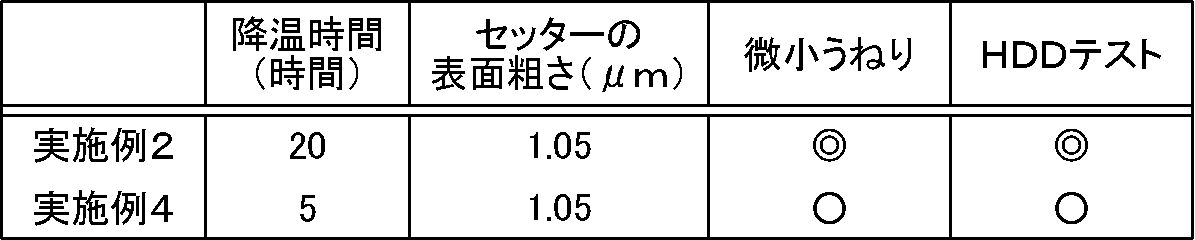

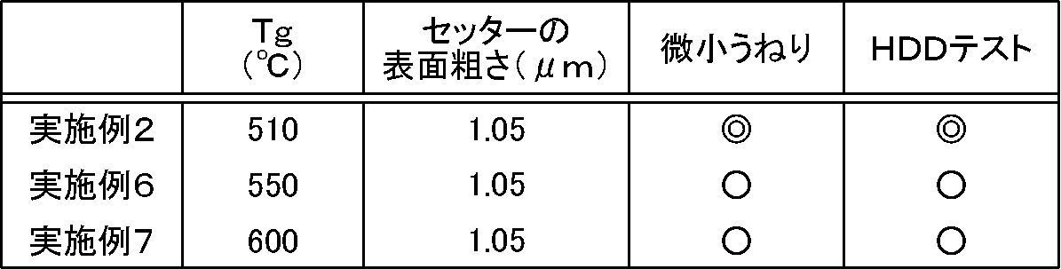
表1に示されるように、表面粗さが0.1~10μmの範囲内であるセッターを用いてガラスブランクスを熱処理に供した実施例1~3は、当該範囲を外れる表面粗さのセッターを用いてガラスブランクスを熱処理に供した比較例1~4と比べて、微小うねりが小さく形状品質の高いガラス基板が得られることが判った。また、これら実施例1~3で得られたガラス基板に磁性膜を形成したメディアは、読み取りエラーの発生頻度が小さく、後発エラーを生じにくいことが判った。その結果、たとえば500GB/枚以上の大容量のメディアとして使用し得るガラス基板が得られることが判った。
実施例4では、実施例2よりも降温時間を短くしてガラス基板を作製した。表2に示されるように、実施例4では、降温時間を短くしたにもかかわらず、得られるガラス基板の微小うねりを抑制でき、形状品質の高いガラス基板が得られることが判った。その結果、磁性膜を形成した実施例4のメディアは、読み取りエラーの発生頻度を小さくすることが可能となり、後発エラーの発生を防止し得ることが判った。その結果、たとえば500GB/枚以上の大容量のメディアとして使用し得るガラス基板が得られることが判った。
実施例5では、実施例2よりも熱処理温度を高くしてガラス基板を作製した。表3に示されるように、実施例5は、熱処理温度をTgよりも50℃も高くしたにもかかわらず、ガラスブランクスとセッターとの融着を防止でき、微小うねりを抑制でき、形状品質の高いガラス基板が得られることが判った。その結果、磁性膜を形成した実施例5のメディアは、読み取りエラーの発生頻度を小さくすることが可能となり、後発エラーの発生を防止し得ることが判った。その結果、たとえば500GB/枚以上の大容量のメディアとして使用し得るガラス基板が得られることが判った。
実施例6や実施例7では、実施例2よりもTgが高いガラス素材を用いてガラス基板を作製した。表4に示されるように、実施例6や実施例7は、ガラス素材のTgが550℃や600℃であり、実施例2よりも高温の熱処理を必要としたにもかかわらず、ガラスブランクスとセッターとの融着を防止でき、微小うねりを抑制でき、形状品質の高いガラス基板が得られることが判った。その結果、磁性膜を形成した実施例6や実施例7のメディアは、読み取りエラーの発生頻度を低くすることが可能となり、後発エラーの発生を防止し得ることが判った。また、実施例6や実施例7のメディアは、高温の熱処理にも耐え得ることが判ったため、磁性膜を形成する際に熱アシスト方式を採用できることが判った。その結果、たとえば500GB/枚以上の大容量のメディアとして使用し得るガラス基板が得られることが判った。
1 溶融炉
2 溶融ガラス
3 下型
4 ガラスゴブ
5 プレス機
6 ガラスブランクス
7 加熱炉
2 溶融ガラス
3 下型
4 ガラスゴブ
5 プレス機
6 ガラスブランクス
7 加熱炉
Claims (3)
- 記録密度が500GB/枚以上のガラス基板の製造方法であって、
ガラス素材を溶融するガラス溶融工程と、溶融ガラスを成形してガラスブランクスを作製する成形工程と、ガラスブランクスを熱処理する熱処理工程とを含み、
前記熱処理工程において、表面粗さが0.1~10μmのセッターで前記ガラスブランクスの両主表面を挟み、熱処理を行う、HDD用ガラス基板の製造方法。 - 前記ガラスブランクスを構成するガラス素材のガラス転移温度(Tg)が、550℃以上である、請求項1記載のHDD用ガラス基板の製造方法。
- 得られたHDD用ガラス基板が、アシスト記録用HDDに使用されるHDD用ガラス基板である、請求項1または2記載のHDD用ガラス基板の製造方法。
Applications Claiming Priority (2)
| Application Number | Priority Date | Filing Date | Title |
|---|---|---|---|
| JP2012075779 | 2012-03-29 | ||
| JP2012-075779 | 2012-03-29 |
Publications (1)
| Publication Number | Publication Date |
|---|---|
| WO2013145503A1 true WO2013145503A1 (ja) | 2013-10-03 |
Family
ID=49258832
Family Applications (1)
| Application Number | Title | Priority Date | Filing Date |
|---|---|---|---|
| PCT/JP2013/000125 Ceased WO2013145503A1 (ja) | 2012-03-29 | 2013-01-15 | Hdd用ガラス基板の製造方法 |
Country Status (2)
| Country | Link |
|---|---|
| JP (1) | JPWO2013145503A1 (ja) |
| WO (1) | WO2013145503A1 (ja) |
Cited By (6)
| Publication number | Priority date | Publication date | Assignee | Title |
|---|---|---|---|---|
| JP2016532235A (ja) * | 2013-10-31 | 2016-10-13 | ホーヤ ガラスディスク ベトナム Ii リミテッド | 磁気ディスク用ガラス基板、及び、熱アシスト磁気記録用磁気ディスク |
| WO2017104513A1 (ja) * | 2015-12-17 | 2017-06-22 | 日本電気硝子株式会社 | 支持ガラス基板の製造方法 |
| KR20170102315A (ko) * | 2014-12-31 | 2017-09-08 | 코닝 인코포레이티드 | 유리 제품을 처리하는 방법 |
| CN109415251A (zh) * | 2016-06-30 | 2019-03-01 | 康宁股份有限公司 | 具有加工的应力分布的玻璃基制品及其制造方法 |
| US10710920B2 (en) | 2014-12-31 | 2020-07-14 | Corning Incorporated | Methods for thermally treating glass articles |
| US20220157340A1 (en) * | 2017-09-29 | 2022-05-19 | Hoya Corporation | Method for manufacturing ring-shaped glass spacer |
Citations (3)
| Publication number | Priority date | Publication date | Assignee | Title |
|---|---|---|---|---|
| JPH08231233A (ja) * | 1994-12-28 | 1996-09-10 | Hoya Corp | 板ガラスの平坦化方法、および該方法を用いた磁気記録媒体の製造方法 |
| JPH09102125A (ja) * | 1995-10-05 | 1997-04-15 | Ngk Insulators Ltd | 磁気ディスク用結晶化ガラス基板の製造方法 |
| JP2008226377A (ja) * | 2007-03-14 | 2008-09-25 | Konica Minolta Opto Inc | ブランク材の残留応力を低減する方法及びブランク材 |
-
2013
- 2013-01-15 WO PCT/JP2013/000125 patent/WO2013145503A1/ja not_active Ceased
- 2013-01-15 JP JP2014507345A patent/JPWO2013145503A1/ja active Pending
Patent Citations (3)
| Publication number | Priority date | Publication date | Assignee | Title |
|---|---|---|---|---|
| JPH08231233A (ja) * | 1994-12-28 | 1996-09-10 | Hoya Corp | 板ガラスの平坦化方法、および該方法を用いた磁気記録媒体の製造方法 |
| JPH09102125A (ja) * | 1995-10-05 | 1997-04-15 | Ngk Insulators Ltd | 磁気ディスク用結晶化ガラス基板の製造方法 |
| JP2008226377A (ja) * | 2007-03-14 | 2008-09-25 | Konica Minolta Opto Inc | ブランク材の残留応力を低減する方法及びブランク材 |
Cited By (21)
| Publication number | Priority date | Publication date | Assignee | Title |
|---|---|---|---|---|
| US9728217B2 (en) | 2013-10-31 | 2017-08-08 | Hoya Glass Disk Vietnam Ii Ltd. | Glass substrate for magnetic disk and magnetic disk for heat assisted magnetic recording |
| JP2016532235A (ja) * | 2013-10-31 | 2016-10-13 | ホーヤ ガラスディスク ベトナム Ii リミテッド | 磁気ディスク用ガラス基板、及び、熱アシスト磁気記録用磁気ディスク |
| KR102152978B1 (ko) * | 2014-12-31 | 2020-09-08 | 코닝 인코포레이티드 | 유리 제품을 처리하는 방법 |
| KR20170102315A (ko) * | 2014-12-31 | 2017-09-08 | 코닝 인코포레이티드 | 유리 제품을 처리하는 방법 |
| JP2018505836A (ja) * | 2014-12-31 | 2018-03-01 | コーニング インコーポレイテッド | ガラス物品の処理方法 |
| US10669196B2 (en) | 2014-12-31 | 2020-06-02 | Corning Incorporated | Methods for treating glass articles |
| US10710920B2 (en) | 2014-12-31 | 2020-07-14 | Corning Incorporated | Methods for thermally treating glass articles |
| CN108367961A (zh) * | 2015-12-17 | 2018-08-03 | 日本电气硝子株式会社 | 支承玻璃基板的制造方法 |
| KR20180095513A (ko) * | 2015-12-17 | 2018-08-27 | 니폰 덴키 가라스 가부시키가이샤 | 지지 유리 기판의 제조 방법 |
| JPWO2017104513A1 (ja) * | 2015-12-17 | 2018-10-04 | 日本電気硝子株式会社 | 支持ガラス基板の製造方法 |
| KR102588111B1 (ko) | 2015-12-17 | 2023-10-12 | 니폰 덴키 가라스 가부시키가이샤 | 지지 유리 기판의 제조 방법 |
| TWI701221B (zh) * | 2015-12-17 | 2020-08-11 | 日商日本電氣硝子股份有限公司 | 支持玻璃基板的製造方法及半導體封裝體的製造方法 |
| WO2017104513A1 (ja) * | 2015-12-17 | 2017-06-22 | 日本電気硝子株式会社 | 支持ガラス基板の製造方法 |
| JP2019524618A (ja) * | 2016-06-30 | 2019-09-05 | コーニング インコーポレイテッド | 操作された応力分布を有するガラス系物品及びその作製方法 |
| KR20190027369A (ko) * | 2016-06-30 | 2019-03-14 | 코닝 인코포레이티드 | 공학적 응력 분포를 갖는 유리계 제품 및 이의 제조 방법 |
| KR102440332B1 (ko) | 2016-06-30 | 2022-09-06 | 코닝 인코포레이티드 | 공학적 응력 분포를 갖는 유리계 제품 및 이의 제조 방법 |
| CN109415251A (zh) * | 2016-06-30 | 2019-03-01 | 康宁股份有限公司 | 具有加工的应力分布的玻璃基制品及其制造方法 |
| JP7405506B2 (ja) | 2016-06-30 | 2023-12-26 | コーニング インコーポレイテッド | 操作された応力分布を有するガラス系物品及びその作製方法 |
| US12040183B2 (en) | 2016-06-30 | 2024-07-16 | Corning Incorporated | Glass-based article with engineered stress distribution and method of making same |
| US20220157340A1 (en) * | 2017-09-29 | 2022-05-19 | Hoya Corporation | Method for manufacturing ring-shaped glass spacer |
| US11705158B2 (en) * | 2017-09-29 | 2023-07-18 | Hoya Corporation | Method for manufacturing ring-shaped glass spacer |
Also Published As
| Publication number | Publication date |
|---|---|
| JPWO2013145503A1 (ja) | 2015-12-10 |
Similar Documents
| Publication | Publication Date | Title |
|---|---|---|
| JP6313314B2 (ja) | 磁気ディスク用ガラス基板の製造方法、ガラス基板の製造方法及び磁気ディスクの製造方法、並びに研削工具 | |
| JPWO2013145503A1 (ja) | Hdd用ガラス基板の製造方法 | |
| JP5321594B2 (ja) | ガラス基板の製造方法、および磁気記録媒体の製造方法 | |
| JP6009194B2 (ja) | 磁気ディスク用板状ガラス素材の製造方法、磁気ディスク用ガラス基板の製造方法 | |
| JP5577290B2 (ja) | 磁気情報記録媒体用ガラス基板の製造方法 | |
| JPWO2010041537A1 (ja) | ガラス基板の製造方法、および磁気記録媒体の製造方法 | |
| JP5536481B2 (ja) | 情報記録媒体用ガラス基板の製造方法及び情報記録媒体の製造方法 | |
| JP2014188668A (ja) | ガラス基板の製造方法 | |
| JP5636508B2 (ja) | ガラス基板、該ガラス基板を用いた情報記録媒体および当該ガラス基板の製造方法 | |
| JP6059739B2 (ja) | ハードディスク用ガラス基板の製造方法 | |
| JP5036323B2 (ja) | 磁気ディスク用ガラス基板の製造方法、磁気ディスクの製造方法およびガラス基板ホルダ | |
| JP5859757B2 (ja) | Hdd用ガラス基板の製造方法 | |
| JP5719030B2 (ja) | 研磨パッドおよび該研磨パッドを用いたガラス基板の製造方法 | |
| JP2014191851A (ja) | 情報記録媒体用ガラス基板の製造方法 | |
| JP5897959B2 (ja) | 情報記録媒体用ガラス基板の製造方法 | |
| JP2008226407A (ja) | 磁気ディスク用基板の製造方法および化学強化装置ならびに磁気ディスクの製造方法 | |
| US20100247976A1 (en) | Glass substrate for a magnetic disk and method of manufacturing the same | |
| CN109285565B (zh) | 磁盘用玻璃基板的制造方法和磁盘的制造方法 | |
| JP6034636B2 (ja) | 磁気記録媒体用基板の製造方法 | |
| JP2013077348A (ja) | Hdd用ガラス基板および該hdd用ガラス基板の製造方法 | |
| JP2010257563A (ja) | 磁気ディスク用ガラス基板及びその製造方法 | |
| JP2008262675A (ja) | 磁気ディスク用ガラス基板 | |
| JP2013133249A (ja) | Hdd用ガラス基板の製造方法、該製造方法により得られるhdd用ガラスブランクスならびにhdd用ガラス基板 | |
| CN105684080A (zh) | 磁盘用玻璃基板以及热辅助磁记录用磁盘 | |
| JP2008140498A (ja) | 記録媒体用ガラス基板の製造方法、記録媒体用ガラス基板及び記録媒体 |
Legal Events
| Date | Code | Title | Description |
|---|---|---|---|
| 121 | Ep: the epo has been informed by wipo that ep was designated in this application |
Ref document number: 13770340 Country of ref document: EP Kind code of ref document: A1 |
|
| ENP | Entry into the national phase |
Ref document number: 2014507345 Country of ref document: JP Kind code of ref document: A |
|
| NENP | Non-entry into the national phase |
Ref country code: DE |
|
| 122 | Ep: pct application non-entry in european phase |
Ref document number: 13770340 Country of ref document: EP Kind code of ref document: A1 |