WO2013145408A1 - 内視鏡装置 - Google Patents
内視鏡装置 Download PDFInfo
- Publication number
- WO2013145408A1 WO2013145408A1 PCT/JP2012/078742 JP2012078742W WO2013145408A1 WO 2013145408 A1 WO2013145408 A1 WO 2013145408A1 JP 2012078742 W JP2012078742 W JP 2012078742W WO 2013145408 A1 WO2013145408 A1 WO 2013145408A1
- Authority
- WO
- WIPO (PCT)
- Prior art keywords
- band
- image signal
- light
- wavelength
- image
- Prior art date
Links
Images


Classifications
-
- A—HUMAN NECESSITIES
- A61—MEDICAL OR VETERINARY SCIENCE; HYGIENE
- A61B—DIAGNOSIS; SURGERY; IDENTIFICATION
- A61B1/00—Instruments for performing medical examinations of the interior of cavities or tubes of the body by visual or photographical inspection, e.g. endoscopes; Illuminating arrangements therefor
- A61B1/06—Instruments for performing medical examinations of the interior of cavities or tubes of the body by visual or photographical inspection, e.g. endoscopes; Illuminating arrangements therefor with illuminating arrangements
-
- A—HUMAN NECESSITIES
- A61—MEDICAL OR VETERINARY SCIENCE; HYGIENE
- A61B—DIAGNOSIS; SURGERY; IDENTIFICATION
- A61B1/00—Instruments for performing medical examinations of the interior of cavities or tubes of the body by visual or photographical inspection, e.g. endoscopes; Illuminating arrangements therefor
- A61B1/00002—Operational features of endoscopes
- A61B1/00004—Operational features of endoscopes characterised by electronic signal processing
- A61B1/00009—Operational features of endoscopes characterised by electronic signal processing of image signals during a use of endoscope
- A61B1/000094—Operational features of endoscopes characterised by electronic signal processing of image signals during a use of endoscope extracting biological structures
-
- A—HUMAN NECESSITIES
- A61—MEDICAL OR VETERINARY SCIENCE; HYGIENE
- A61B—DIAGNOSIS; SURGERY; IDENTIFICATION
- A61B1/00—Instruments for performing medical examinations of the interior of cavities or tubes of the body by visual or photographical inspection, e.g. endoscopes; Illuminating arrangements therefor
- A61B1/00002—Operational features of endoscopes
- A61B1/00043—Operational features of endoscopes provided with output arrangements
- A61B1/00045—Display arrangement
- A61B1/0005—Display arrangement combining images e.g. side-by-side, superimposed or tiled
-
- A—HUMAN NECESSITIES
- A61—MEDICAL OR VETERINARY SCIENCE; HYGIENE
- A61B—DIAGNOSIS; SURGERY; IDENTIFICATION
- A61B1/00—Instruments for performing medical examinations of the interior of cavities or tubes of the body by visual or photographical inspection, e.g. endoscopes; Illuminating arrangements therefor
- A61B1/04—Instruments for performing medical examinations of the interior of cavities or tubes of the body by visual or photographical inspection, e.g. endoscopes; Illuminating arrangements therefor combined with photographic or television appliances
- A61B1/044—Instruments for performing medical examinations of the interior of cavities or tubes of the body by visual or photographical inspection, e.g. endoscopes; Illuminating arrangements therefor combined with photographic or television appliances for absorption imaging
-
- A—HUMAN NECESSITIES
- A61—MEDICAL OR VETERINARY SCIENCE; HYGIENE
- A61B—DIAGNOSIS; SURGERY; IDENTIFICATION
- A61B1/00—Instruments for performing medical examinations of the interior of cavities or tubes of the body by visual or photographical inspection, e.g. endoscopes; Illuminating arrangements therefor
- A61B1/06—Instruments for performing medical examinations of the interior of cavities or tubes of the body by visual or photographical inspection, e.g. endoscopes; Illuminating arrangements therefor with illuminating arrangements
- A61B1/0638—Instruments for performing medical examinations of the interior of cavities or tubes of the body by visual or photographical inspection, e.g. endoscopes; Illuminating arrangements therefor with illuminating arrangements providing two or more wavelengths
-
- A—HUMAN NECESSITIES
- A61—MEDICAL OR VETERINARY SCIENCE; HYGIENE
- A61B—DIAGNOSIS; SURGERY; IDENTIFICATION
- A61B1/00—Instruments for performing medical examinations of the interior of cavities or tubes of the body by visual or photographical inspection, e.g. endoscopes; Illuminating arrangements therefor
- A61B1/06—Instruments for performing medical examinations of the interior of cavities or tubes of the body by visual or photographical inspection, e.g. endoscopes; Illuminating arrangements therefor with illuminating arrangements
- A61B1/0646—Instruments for performing medical examinations of the interior of cavities or tubes of the body by visual or photographical inspection, e.g. endoscopes; Illuminating arrangements therefor with illuminating arrangements with illumination filters
-
- A—HUMAN NECESSITIES
- A61—MEDICAL OR VETERINARY SCIENCE; HYGIENE
- A61B—DIAGNOSIS; SURGERY; IDENTIFICATION
- A61B1/00—Instruments for performing medical examinations of the interior of cavities or tubes of the body by visual or photographical inspection, e.g. endoscopes; Illuminating arrangements therefor
- A61B1/06—Instruments for performing medical examinations of the interior of cavities or tubes of the body by visual or photographical inspection, e.g. endoscopes; Illuminating arrangements therefor with illuminating arrangements
- A61B1/0655—Control therefor
-
- A—HUMAN NECESSITIES
- A61—MEDICAL OR VETERINARY SCIENCE; HYGIENE
- A61B—DIAGNOSIS; SURGERY; IDENTIFICATION
- A61B1/00—Instruments for performing medical examinations of the interior of cavities or tubes of the body by visual or photographical inspection, e.g. endoscopes; Illuminating arrangements therefor
- A61B1/06—Instruments for performing medical examinations of the interior of cavities or tubes of the body by visual or photographical inspection, e.g. endoscopes; Illuminating arrangements therefor with illuminating arrangements
- A61B1/0661—Endoscope light sources
- A61B1/0684—Endoscope light sources using light emitting diodes [LED]
-
- A—HUMAN NECESSITIES
- A61—MEDICAL OR VETERINARY SCIENCE; HYGIENE
- A61B—DIAGNOSIS; SURGERY; IDENTIFICATION
- A61B1/00—Instruments for performing medical examinations of the interior of cavities or tubes of the body by visual or photographical inspection, e.g. endoscopes; Illuminating arrangements therefor
Definitions
- the present invention relates to an endoscope apparatus, and more particularly to an endoscope apparatus capable of displaying blood vessels inside a subject.
- the endoscope apparatus includes an endoscope, an image processing apparatus connected to the endoscope, and an observation monitor.
- the lesioned part is imaged by an imaging element provided at the distal end of the endoscope insertion part, and the image is displayed on the monitor. The surgeon can perform diagnosis or necessary treatment while looking at the image displayed on the monitor.
- Some endoscope apparatuses can perform not only normal light observation using white light but also special light observation using special light such as infrared light in order to observe internal blood vessels.
- infrared endoscope apparatus for example, indocyanine green (ICG) having absorption peak characteristics in near-infrared light having a wavelength of around 805 nm is injected into a patient's blood as a drug. Then, the subject is irradiated with infrared light having wavelengths of about 805 nm and about 930 nm in a time division manner from the light source device. The signal of the subject image captured by the CCD is input to the processor of the infrared endoscope apparatus.
- ICG indocyanine green
- the processor converts an image around a wavelength of 805 nm into a green signal (G) and an image around a wavelength of 930 nm.
- G green signal
- B blue signal
- ESD Endoscopic Submucosal Dissection
- ESD Endoscopic Submucosal Dissection
- ESD Endoscopic Submucosal Dissection
- the operator confirms the position of such a blood vessel and performs treatment such as incision. Blood vessels that can cause severe bleeding run from the submucosa to the intrinsic muscle layer. When severe bleeding occurs in procedures such as ESD, the operation time becomes longer because hemostasis must be performed each time.
- the present invention has been made in view of the above-described problems, and provides an endoscope apparatus that can clearly display blood vessels in the deep mucosa without performing a complicated operation of drug administration. Objective.
- an illumination unit that irradiates a subject with at least one illumination light having a predetermined wavelength band, and imaging the return light from the subject based on the illumination of the illumination unit And the first image signal having the peak wavelength of the spectral characteristic between the wavelength band including the maximum value and the wavelength band including the maximum value in the absorption characteristics of the living tissue after imaging by the imaging unit, Based on a predetermined first band image signal among a plurality of band image signals obtained by performing the decomposition process on the plurality of spatial frequency bands, and a band decomposition processing unit obtained by performing the decomposition process on the band decomposition processing unit, It is possible to provide an endoscope apparatus that includes an image processing unit that generates an image signal that has been subjected to enhancement processing and has undergone enhancement correction, and a display unit that displays the image signal that has undergone enhancement correction.
- FIG. 1 is a configuration diagram showing a configuration of an endoscope apparatus according to a first embodiment of the present invention. It is a figure which shows the structure of the rotation filter 14 in connection with 1st Embodiment. It is a figure for demonstrating the flow of the whole process in the narrow-band light observation in connection with 1st Embodiment. A process of generating an image of a plurality of frequency bands from one wavelength image related to the first embodiment and performing an enhancement process on one of the generated images of the plurality of frequency bands It is a figure for demonstrating. It is a figure which shows the light absorption characteristic of the venous blood in connection with 1st Embodiment.
- FIG. It is a schematic diagram of the image which image
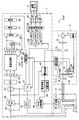
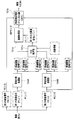
- FIG. 1 is a configuration diagram showing a configuration of an endoscope apparatus according to the present embodiment.
- an endoscope apparatus 1 includes an electronic device having a CCD 2 that is an imaging device as a biological image information acquisition unit or a biological image information acquisition unit that is inserted into a body cavity and images tissue in the body cavity.
- the endoscope apparatus 1 has two modes, a normal light observation mode and a narrow band light observation mode. In the following description, since the normal light observation mode of the endoscope apparatus 1 is the same as the conventional normal light observation mode, description of the configuration of the normal light observation mode is omitted, and mainly the narrowband light observation mode. explain.
- the CCD 2 constitutes an imaging unit or imaging means that receives the return light of the illumination light applied to the subject and images the subject.
- the light source device 4 as an illuminating means or an illuminating unit includes a xenon lamp 11 that emits illumination light (white light), a heat ray cut filter 12 that blocks heat rays of white light, and a light amount of white light that passes through the heat ray cut filter 12.
- the xenon lamp 11, the rotary filter 14, and the light guide 15 constitute an irradiation unit or irradiation means for illuminating the subject with illumination light.
- FIG. 2 is a diagram showing the configuration of the rotary filter 14.
- the rotary filter 14 is a filter that transmits light from the xenon lamp 11 that is a light source.
- the rotary filter 14 as a wavelength band limiting unit or wavelength band limiting means is configured in a disc shape and has a structure with the center as a rotation axis, and has two filter groups. .
- R (red) filter units 14 r and G (green) filter units that constitute a filter set for outputting surface-sequential light having spectral characteristics for normal light observation along the circumferential direction.
- the 14g, B (blue) filter unit 14b is arranged as the first filter group.
- three filters 14-600, 14-630, and 14-540 that transmit light of a predetermined narrowband wavelength along the circumferential direction are used as a second filter group. Has been placed.
- the filter 14-600 is configured to transmit light having a wavelength near 600 nm ( ⁇ 1) as narrowband light.
- the filter 14-630 is configured to transmit light having a wavelength near 630 nm ( ⁇ 2) as narrowband light.
- the filter 14-540 is configured to transmit light in the vicinity of a wavelength of 540 nm ( ⁇ 3) as narrowband light.
- near means a distribution having a central wavelength of 600 nm and a width in the range of, for example, 20 nm (that is, wavelengths from 590 nm to 610 nm before and after the wavelength of 600 nm) when the wavelength is near 600 nm. It means that it has narrow band light. The same applies to the other wavelengths, wavelength 630 nm and wavelength 540 nm described later.
- the rotary filter 14 is disposed on an optical path from the xenon lamp 11 that is an emission part of the illumination light to the imaging surface of the CCD 2, and at least one of a plurality of wavelength bands of illumination light (here, three) in each mode.
- the wavelength band is limited to be narrowed.
- the control circuit 17 controls the motor 18 for rotating the rotary filter 14 to control the rotation of the rotary filter 14.
- a rack 19a is connected to the motor 18, a motor (not shown) is connected to the pinion 19b, and the rack 19a is attached so as to be screwed to the pinion 19b.
- the control circuit 17 can move the rotary filter 14 in the direction indicated by the arrow d by controlling the rotation of the motor connected to the pinion 19b. Therefore, the control circuit 17 puts the first filter group on the optical path in the normal light observation mode and the second filter group on the optical path in the narrow-band light observation mode according to a mode switching operation by the user described later.
- the motor connected to the pinion 19b is controlled so as to be positioned.
- electric power is supplied from the power supply unit 10 to a motor (not shown) connected to the xenon lamp 11, the diaphragm device 13, the rotary filter motor 18, and the pinion 19b.
- the illumination unit or the illumination unit irradiates the subject with at least one illumination light having a predetermined wavelength band (here, three narrow-band lights).
- a predetermined wavelength band here, three narrow-band lights.
- two of the three illumination lights are narrowband light for highlighting a blood vessel in a depth of 1 to 2 mm from the surface layer, and the remaining one is a predetermined distance from the surface layer of the subject.
- it is narrowband light as the third illumination light that can be transmitted only in the vicinity of the surface layer.
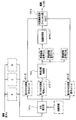
- the video processor 7 includes a CCD driver circuit 20 that is a CCD driver, an amplifier 22, a process circuit 23, an A / D converter 24, a white balance circuit (hereinafter referred to as WB) 25, a selector 100, an image processing unit 101, and a selector. 102, ⁇ correction circuit 26, enlargement circuit 27, enhancement circuit 28, selector 29, synchronization memories 30, 31, 32, image processing circuit 33, D / A converters 34, 35, 36, timing generator (hereinafter referred to as T.30).
- G) 37 a mode switching circuit 42, a dimming circuit 43, a dimming control parameter switching circuit 44, a control circuit 200, and a combining circuit 201 as a display image generating means or a display image generating unit.
- the CCD drive circuit 20 drives the CCD 2 provided in the electronic endoscope 3 and outputs to the CCD 2 a frame sequential imaging signal synchronized with the rotation of the rotary filter 14.
- the amplifier 22 amplifies a surface sequential imaging signal obtained by imaging the tissue in the body cavity by the CCD 2 via the objective optical system 21 provided at the tip of the electronic endoscope 3.
- the process circuit 23 performs correlated double sampling, noise removal, and the like on the frame sequential imaging signal via the amplifier 22.
- the A / D converter 24 converts the frame sequential imaging signal that has passed through the process circuit 23 into a digital sequential frame sequential image signal.
- W. B25 is equivalent to the brightness of the R signal of the image signal and the B signal of the image signal with respect to the G signal of the image signal, for example, with respect to the frame sequential image signal digitized by the A / D converter 24.
- the gain is adjusted as described above, and white balance processing is executed.
- the white balance adjustment in B25 is performed on the basis of the brightness of the return light of the narrow band light near the wavelength of 600 nm.
- the selector 100 is a W.W.
- the frame sequential image signal from B25 is distributed to each unit in the image processing unit 101 and output.
- the image processing unit 101 is an image signal processing unit or image signal processing means for converting the RGB image signals for normal light observation or the three image signals for narrow band light observation from the selector 100 into display image signals. It is.
- the image processing unit 101 outputs image signals in the normal light observation mode and the narrow band light observation mode to the selector 102 in accordance with the selection signal SS from the control circuit 200 based on the mode signal.
- the selector 102 sequentially outputs the frame sequential image signals of the normal light observation image signal and the narrowband light observation image signal from the image processing unit 101 to the ⁇ correction circuit 26 and the synthesis circuit 201.
- the ⁇ correction circuit 26 performs ⁇ correction processing on the frame sequential image signal from the selector 102 or the synthesis circuit 201.
- the enlargement circuit 27 enlarges the frame sequential image signal that has been subjected to the ⁇ correction processing by the ⁇ correction circuit 26.
- the enhancement circuit 28 performs edge enhancement processing on the frame sequential image signal that has been enlarged by the enlargement circuit 27.
- the selector 29 and the synchronization memories 30, 31, and 32 are for synchronizing the frame sequential image signals from the enhancement circuit 28.
- the image processing circuit 33 reads out the frame sequential image signals stored in the synchronization memories 30, 31, 32, and performs a moving image color misregistration correction process.
- the D / A converters 34, 35, 36 convert the image signal from the image processing circuit 33 into an RGB analog video signal and output it to the observation monitor 5.
- T.A. G 37 receives a synchronization signal synchronized with the rotation of the rotary filter 14 from the control circuit 17 of the light source device 4, and outputs various timing signals to each circuit in the video processor 7.
- the electronic endoscope 2 is provided with a mode switching switch 41 for switching between the normal light observation mode and the narrow-band light observation mode, and the output of the mode switching switch 41 is the mode switching in the video processor 7. It is output to the circuit 42.
- the mode switching circuit 42 of the video processor 7 outputs a control signal to the dimming control parameter switching circuit 44 and the control circuit 200.
- the dimming circuit 43 controls the diaphragm device 13 of the light source device 4 and performs appropriate brightness control based on the dimming control parameter from the dimming control parameter switching circuit 44 and the imaging signal passed through the process circuit 23. ing.
- Each circuit in the video processor 7 executes a predetermined process according to the designated mode. Processing corresponding to each of the normal light observation mode and the narrow band light observation mode is executed, and the normal monitor image or the narrow band light observation image is displayed on the observation monitor 5.
- the observation monitor 5 is a display unit or a display unit that displays the image signal subjected to the enhancement correction.
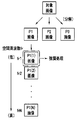
- FIG. 3 is a diagram for explaining the overall processing flow in the narrow-band light observation according to the present embodiment.
- the surgeon inserts the insertion portion of the endoscope into the body cavity and positions the distal end portion of the insertion portion of the endoscope near the lesioned portion under the normal light observation mode.
- the operator operates the mode switch 41 to observe a relatively thick blood vessel that travels from the submucosal layer to the intrinsic muscle layer and has a diameter of, for example, 1 to 2 mm. Then, the endoscope apparatus 1 is switched to the narrow band light observation mode.
- control circuit 17 of the endoscope apparatus 1 controls the motor connected to the pinion 19b so that the light transmitted through the second filter group is emitted from the light source device 4. The position of the rotary filter 14 is moved. Further, the control circuit 200 also controls various circuits in the video processor 7 so as to perform image processing for observation with a narrow band wavelength.
- illumination light of a narrow-band wavelength is emitted from the distal end portion of the insertion portion of the endoscope 3 from the illumination light generation unit 51, passes through the mucosa layer, The blood vessel 61 traveling through the submucosa and the proper muscle layer is irradiated.
- the illumination light generation part 51 is comprised including the light source device 4, the rotation filter 14, the light guide 15, etc., and radiate
- narrowband light having a wavelength of about 600 nm, narrowband light having a wavelength of about 630 nm, and narrowband light having a wavelength of about 540 nm are emitted from the light source device 4 sequentially and sequentially to irradiate the subject. Is done.
- Reflected light of narrowband light having a wavelength of about 600 nm, narrowband light having a wavelength of about 630 nm, and narrowband light having a wavelength of about 540 nm is received by the reflected light receiving unit 52 that is a CCD 2.
- the CCD 2 outputs an imaging signal of each reflected light and is supplied to the selector 100 via the amplifier 22 and the like.
- the selector 100 is a T.W. According to a predetermined timing from G37, the first image signal P1 near the wavelength of 600 nm, the second image signal P2 near the wavelength of 630 nm, and the third image signal P3 near the wavelength of 540 nm are held, and an image processing unit 101.
- the image processing unit 101 includes a band separation processing unit 104, an enhancement processing unit 101a, and a color conversion processing unit 101b for the narrow band light observation mode.
- an endoscopic device 1 is used to incision and exfoliate the submucosal layer on the inner wall of the digestive tract such as the stomach, esophagus, large intestine, etc. You must not cut the thick blood vessels.
- the surgeon can clearly draw a blood vessel below the surface of the living tissue.
- FIG. 4 is a diagram for explaining processing for generating an image of a plurality of frequency bands from one wavelength image and performing enhancement processing on one of the generated images of the plurality of frequency bands. It is.
- the band resolution processing unit 104 performs N (N is a natural number of 1 or more) of the first image signal P1 near the wavelength of 600 nm by spatial frequency analysis, for example, by spatial frequency division processing.
- the image signal is divided into spatial frequency band image signals (hereinafter referred to as band image signals).
- band image signals spatial frequency band image signals
- the first image signal P1 is between the wavelength band including the maximum value ACmax and the wavelength band at the minimum value ACmin in the absorption characteristics of the living tissue after imaging by the imaging device 2. It is an image signal having a peak wavelength of spectral characteristics.
- the band resolution processing unit 104 after imaging by the imaging device 2, has an image signal P1 having a peak wavelength of spectral characteristics between the wavelength band including the maximum value ACmax and the wavelength band of the minimum value ACmin in the absorption characteristics of the living tissue.
- a band decomposition processing means or a band decomposition processing unit for performing the decomposition processing into a plurality of spatial frequency bands is configured.
- the band resolution processing unit 104 may be configured to divide the second image signal P2 near the wavelength of 630 nm into N band image signals. That is, the band resolution processing unit 104 may generate two or more N band images for each of m (m is a natural number of 1 or more) wavelength images. 4, m is 1, and N band image signals P1 (1), P1 (2),... P1 (N) are generated from the first image signal P1. In that case, after the imaging by the imaging device 2, the band resolution processing unit 104 has a second spectral wavelength peak wavelength between the wavelength band including the maximum value ACmax and the wavelength band at the minimum value ACmin in the absorption characteristics of the living tissue.
- the image signal P2 is also decomposed into a plurality of spatial frequency bands, and the enhancement processing unit 101a performs the decomposition process on the second image signal P2 in addition to the band image signal related to the first image signal P1.
- enhancement processing is performed to generate an image signal subjected to enhancement correction.
- the band decomposition processing unit 104 performs a decomposition process on at least one wavelength band of the medical image into a plurality of spatial frequency bands to generate a plurality of band images, or a band decomposition processing unit or a space.
- a frequency division processing means or a spatial frequency division processing unit is configured.
- the N spatial frequency bands are bands of the spatial frequencies fr1, fr2,..., FrN.
- the spatial frequency is lowest at fr1 and higher in order from fr2 to frN. Therefore, among the N band image signals P1 (1), P1 (2),... P1 (N), the band image signal P1 (1) is the image signal with the lowest spatial frequency.
- the band image signal in the vicinity of P1 (1) has information on a biological structure such as a thicker blood vessel).
- the band image signal P1 (N) is the image signal with the highest spatial frequency (for example, P1 ( N)
- the band image signal in the vicinity has information on the surface uneven structure such as blood vessels and glandular structures on the thinner mucosal surface layer. It is generated by performing a spatial frequency filtering process using a mask corresponding to the frequency frk.
- the enhancement processing unit 101 a performs image processing to be described later for enhancing the image of the blood vessel 61, and the color conversion processing unit 101 b assigns each image signal to each RGB channel of the observation monitor 5 and supplies it to the selector 102.
- the screen 5a of the observation monitor 5 a relatively thick blood vessel 61 in the deep mucosa is displayed with high contrast. Therefore, the surgeon can perform ESD on the lesioned part while paying attention to the blood vessel 61 displayed on the observation monitor 5 and traveling through the submucosa and the proper muscle layer.
- FIG. 5 is a diagram showing light absorption characteristics of venous blood. The vertical axis in FIG.
- the illumination light of the three narrow-band lights is also affected by the scattering characteristics of the living tissue itself. However, since the scattering characteristics of the living tissue itself are substantially monotonously decreased with respect to the increase in wavelength, FIG. This will be explained as the tissue absorption characteristics.
- venous blood contains oxygenated hemoglobin (HbO 2 ) and reduced hemoglobin (Hb) (hereinafter simply referred to as hemoglobin) in a ratio of approximately 60:40 to 80:20.
- HbO 2 oxygenated hemoglobin
- Hb reduced hemoglobin
- FIG. 5 shows the absorption characteristics of venous blood light for each wavelength from 400 nm to about 800 nm. In the range from 550 nm to 750 nm, the absorption coefficient shows a maximum value at a point of about a wavelength of 576 nm, and a point at a wavelength of 730 nm. Indicates the minimum value.
- Narrow band light in the vicinity of a wavelength of 600 nm (hereinafter, referred to as first narrow band light NL1) has a maximum value ACmin (here, absorption coefficient at a wavelength of 576 nm) to a minimum value ACmin (here, absorption coefficient at a wavelength of 730 nm) of absorption characteristics of hemoglobin. )
- ACmin absorption coefficient at a wavelength of 576 nm
- ACmin absorption coefficient at a wavelength of 730 nm
- Narrow band light having a wavelength of around 630 nm (hereinafter referred to as second narrow band light NL2) is also light within the wavelength band R from the maximum value ACmax to the minimum value ACmin of the absorption characteristic of hemoglobin, but the first narrowband light. It is light in a wavelength band that is longer than the wavelength of NL1, has a low absorption coefficient, and suppresses the scattering characteristics of living tissue. Suppressing the scattering characteristic means that the scattering coefficient is lowered toward the long wavelength side.
- the light source device 4 includes the first illumination light NL1 having the peak wavelength of the spectral characteristics between the wavelength band including the maximum value ACmax and the wavelength band including the minimum value ACmin in the absorption characteristics of the living tissue, and the first illumination light.
- Second illumination light NL2 having a peak wavelength of a spectral characteristic in which the value of the absorption characteristic is lower than the image signal P1 by NL1 and the scattering characteristic of the living tissue is suppressed is irradiated.
- Narrow band light with a wavelength of around 540 nm (hereinafter referred to as third narrow band light NL3) is light in a wavelength band outside the wavelength band R from the maximum value ACmax to the minimum value ACmin of the absorption characteristic of hemoglobin. Illumination light that can be transmitted by a predetermined distance from the surface layer portion of the surface.
- the CCD 2 outputs an imaging signal for each image of the three narrow band lights. Therefore, each image includes a plurality of pixel signals based on the return lights of the first, second, and third narrowband lights NL1, NL2, and NL3.
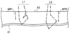
- FIG. 6 is a diagram for explaining the light propagation volume in the living tissue of the first narrowband light NL1 ( ⁇ 1) and the second narrowband light NL2 ( ⁇ 2).
- Each of the first narrowband light NL1 and the second narrowband light NL2 repeats the multiple scattering process in the living tissue, and as a result, is emitted from the mucosal surface as return light.
- the first narrowband light NL1 and the second narrowband light NL2 have mean free paths MFP1 and MFP2, respectively.
- the mean free path MFP1 of the first narrowband light NL1 is shorter than the mean free path MFP2 of the second narrowband light NL2.
- the first narrowband light NL1 having a wavelength of 600 nm ( ⁇ 1) reaches the vicinity of the blood vessel 61, and the second narrowband light NL2 having a wavelength of 630 nm ( ⁇ 2) is slightly smaller than the blood vessel 61. To a deep position.
- the mean free path of the third narrowband light NL3 near the wavelength of 540 nm is shorter than the mean free paths MFP1 and MFP2 of the two narrowband lights NL1 and NL2.
- Narrow-band light NL3 reaches only a relatively shallow region of the surface layer of the mucosal surface.
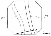
- FIG. 17 is a schematic diagram of an image obtained by photographing the abdominal cavity of an animal using a spectroscopic endoscope apparatus capable of irradiating narrow-band illumination light in a time series with a center wavelength of 10 nm.
- the blood vessel V1 and the blood vessel V2 in the image are thick blood vessels that run from the upper left direction to the lower right direction in the image.
- the blood vessel V1 is located deeper from the mucosal surface than the blood vessel V2.
- a total of 15 patterns of monochrome images were taken in 10 nm steps from 540 nm to 680 nm.
- FIG. 18 is a graph in which the vertical axis represents the intensity (logarithmically displayed pixel values) on Line-A in each of the plurality of monochrome images in FIG.
- the horizontal axis in FIG. 18 represents the position of the pixel on Line-A in each image.
- the blood vessel V1 has a pixel position in the vicinity of 25 to 50
- the blood vessel V2 has a pixel position in the vicinity of 75 to 110.
- the illumination wavelength at which the intensity is attenuated in both the blood vessel V2 present in the relatively shallow portion and the blood vessel V1 located in the deep portion that is, the wavelength at which the illumination light is strongly absorbed in the blood vessel V1 and the blood vessel V2, From FIG. 18, it can be seen that it is approximately 590 nm to 620 nm.
- narrow-band light of about 590 nm to 620 nm is important wavelength information.
- the blood vessel V1 exists in a portion about 1 mm to 2 mm deep from the mucosal surface.
- the result of this experiment is substantially the same as the theoretical calculation result by Beer-Lambert (a relatively thick blood vessel can be displayed with high contrast by using narrow-band light between 15 nm before and after a wavelength of 600 nm). .
- the illuminating means or the illuminating unit including the light source device 4 has illumination light having a peak wavelength of spectral characteristics between the wavelength band including the maximum value ACmax and the wavelength band of the minimum value ACmin in the absorption characteristics of living tissue.
- Narrow-band light NL1 and illumination light NL2 that has a peak wavelength of spectral characteristics with a low value in the absorption characteristic of the return light by the narrow-band light NL1 and suppressed scattering characteristics of living tissue To do.
- the illuminating means or illuminating unit including the light source device 4 also irradiates the third illuminating light NL3 that can be transmitted by a predetermined distance from the surface layer of the subject.
- An image of narrowband light NL1 having a wavelength of 600 nm ( ⁇ 1) is composed of a plurality of lines, and each line includes a plurality of pixels.
- the enhancement processing unit 101a is a band image signal P1 (1) having the lowest spatial frequency among a plurality of band images obtained by performing band decomposition processing on the image signal of the narrowband light NL1 having a wavelength of 600 nm ( ⁇ 1).
- the pixel value of each pixel is multiplied by a predetermined gain coefficient to perform enhancement processing, and the enhancement corrected image signal BEP1 ( ⁇ 1) subjected to enhancement correction is output to the color conversion unit 101b.
- the enhancement processing unit 101a generates an image signal that is enhanced and corrected by performing enhancement processing based on a predetermined band image signal among a plurality of band image signals obtained by the decomposition processing by the band decomposition processing unit 104.
- An image processing means or an image processing unit is configured.
- the enhancement processing unit 101a performs the enhancement correction image signal BEP1 (enhanced and corrected by performing the process of enhancing only the band image signal having the lowest spatial frequency among the plurality of band image signals obtained by the band decomposition process. ⁇ 1) is generated.
- the enhancement processing unit 101a emphasizes only the band image signal having the lowest spatial frequency among the plurality of band image signals obtained by the band decomposition process, but the band image having the lowest spatial frequency. Emphasis processing may be performed on signals other than signals (for example, the band image signal P1 (2) having the second lowest spatial frequency may be emphasized). Note that enhancement processing may be performed on two or more band image signals having a low spatial frequency among a plurality of spatial frequency bands.
- the color conversion processing unit 101b receives the second image signal P2 ( ⁇ 2), the third image signal P3 ( ⁇ 3), and the enhanced corrected image signal BEP1 ( ⁇ 1). In the color conversion processing unit 101b, a process of assigning the second image signal P2 ( ⁇ 2), the third image signal P3 ( ⁇ 3), and the enhanced corrected image signal BEP1 ( ⁇ 1) to the RGB channel is performed.
- the luminance value Im ( ⁇ 3) of the signal P3 ( ⁇ 3) is assigned to the RGB channel.
- the relatively thick blood vessel 61 in the deep part is displayed in a slightly reddish color, so that it is easy for the operator to understand. Further, since narrow band light having a wavelength of about 540 nm is used as the third narrow band light NL3, capillaries and hemorrhages existing in a relatively shallow region from the surface of the living tissue are displayed in substantially yellow.
- the deep blood vessel 61 is displayed in a slightly blue or blue-green color, and the capillaries in the surface layer are also displayed in red to brown, so that it is easy for the operator to understand.
- ⁇ is a numerical value of approximately 1.0 to 1.5
- ⁇ is approximately 2.0 to 2.6
- the color tone of the deep blood vessel is blue-green
- the color tone of the mucous membrane is similar to that of normal observation, so that the operator can easily observe without stress.
- ⁇ is a numerical value of approximately 2.3 to 2.7
- ⁇ is approximately 2.3 to 2.7
- narrowband light near a wavelength of 540 nm is used as a B channel
- narrowband light near a wavelength of 630 nm is used as a G channel
- narrowband light near a wavelength of 600 nm that is, an enhanced correction image.
- the signal BEP1 ( ⁇ 1)) may be assigned to the R channel.
- narrowband light having a wavelength of about 540 nm may be assigned to the B channel and G channel, and narrowband light having a wavelength of about 600 nm or narrowband light having a wavelength of about 630 nm may be assigned to the R channel.
- the color balance adjustment when assigning narrowband light near the wavelength of 540 nm to the B channel, narrowband light near the wavelength of 600 nm to the G channel, and narrowband light near the wavelength of 630 nm to the R channel, the R channel It is desirable to amplify the B channel signal with respect to the above signal.
- the signal intensity of the narrow band light near the wavelength of 600 nm is not corrected, and the signal intensity of the narrow band light near the wavelength of 540 nm assigned to the B channel is 0. 0 of the signal intensity of the narrow band light near the wavelength of 630 nm assigned to the R channel.
- the two signals are adjusted to be 7 to 2.5 times.
- the color conversion process may be performed after the color balance adjustment, or the color balance process may be performed after the color conversion process.
- the difference in color tone between the mucous membrane, white-colored fibrous tissue, yellow bleeding, black carbonized region, and blood vessels whose color tone is red to magenta is thicker. It is possible to obtain a display image that is easier to perform.
- Such a color balance adjustment circuit for color balance adjustment is disclosed in W.W. You may provide in the front
- the color balance adjustment circuit outputs the signal of the narrow band light near the wavelength of 540 nm allocated to the B channel.
- the signal of the narrowband light near the wavelength of 630 nm to be assigned to the R channel is about 0.6 to 1.0 times.
- the color balance adjustment may be performed in the color conversion processing unit 101b, or may be performed by adjusting the intensity of illumination light in the light source device 4, or for each color of the color filter of the image sensor.
- the transmission may be adjusted.
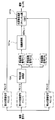
- FIG. 7 is a diagram for explaining a flow of processing for an image obtained from the image sensor 2 in the image processing unit 101.
- the three images from the image sensor 2 are input to the image processing unit 101 as first to third image signals P1, P2, and P3.
- band decomposition processing by the band decomposition processing unit 104 is performed on the image signal P1.
- the band decomposition processing unit 104 decomposes the image signal P1 into a plurality of predetermined spatial frequencies, here, N bands of spatial frequencies fr1 to frN, and N band image signals P1 (1), P1 (2),... P1 (N) is generated.
- the enhancement processing unit 101a performs enhancement processing by, for example, multiplying the band image signal P1 (1), which is the image having the lowest spatial frequency, among N band image signals by a predetermined gain coefficient. . That is, the brightness is adjusted so that only the band image signal P1 (1), which is the image having the lowest spatial frequency, is enhanced. Therefore, only the band image signal P1 (1) including only a relatively thick blood vessel image is enhanced.
- the color conversion processing unit 101b applies color to the second image signal P2, the third image signal P3, and the enhancement-corrected image signal BEP1 ( ⁇ 1) obtained by the enhancement process by the channel assignment as described above. A conversion process is performed and output to the observation monitor 5.
- the return light image is subjected to band decomposition processing for band decomposition into a plurality of band image signals. Then, by performing enhancement processing on at least one band image signal having a low spatial frequency among the obtained plurality of band image signals, relatively thick blood vessels in a relatively deep part of the biological mucous membrane are emphasized. Displayed on the screen of the observation monitor 5. Therefore, the surgeon can confirm a relatively thick blood vessel and perform a desired treatment such as ESD.
- band decomposition processing by spatial frequency division processing is performed on the first image signal P1 near the wavelength of 600 nm, and enhancement processing is performed on the band image signal having the lowest spatial frequency.
- the space for the second image signal P2 near the wavelength of 630 nm Frequency division processing may be performed, and enhancement processing may be performed on a band image signal having the lowest spatial frequency.
- narrowband light near the wavelength of 540 nm is assigned to the B channel
- narrowband light near the wavelength of 600 nm is assigned to the G channel
- narrowband light near the wavelength of 630 nm is assigned to the R channel.
- a thick blood vessel is displayed in blue to blue-green.
- band decomposition processing is performed on one image signal. For example, both the first image signal P1 near the wavelength of 600 nm and the second image signal P2 near the wavelength of 630 nm are processed.
- the band resolution processing is performed to select a band image having a low spatial frequency (for example, the lowest spatial frequency) from each of the two band resolution processings, and both are enhanced to obtain an enhanced corrected image signal. You may do it.
- narrowband light having a wavelength of about 540 nm is assigned to the B channel
- narrowband light having a wavelength of about 600 nm is assigned to the G channel
- narrowband light having a wavelength of about 630 nm is assigned to the R channel.
- a thick blood vessel is displayed in a bluish color.
- the enhancement processing is performed on the band image signal with the lowest spatial frequency.
- the enhancement processing is performed on the band image signal with the second or third lowest spatial frequency instead of the lowest band image signal. Processing may be performed.
- the endoscope apparatus 1 it is possible to display blood vessels in a portion close to the surface layer portion of the biological mucosa using the third narrowband light NL3.
- the third narrow-band light NL3 near the wavelength of 540 nm is used, the state of the capillary blood vessel in the surface layer portion is displayed on the screen of the observation monitor 5 simultaneously with the thick blood vessel. Therefore, the surgeon uses the endoscopic image on the screen of the observation monitor 5 not only for the treatment but also for the diagnosis of living tissue, for example, cancer, from the state of the capillary blood vessels, for example, the degree of concentration or dispersion of the blood capillaries.
- the present invention can be used for the presence diagnosis of cancer, the range diagnosis for specifying the range of cancer, and the differential diagnosis for determining benign or malignant of the affected part. Furthermore, it is also possible to perform a depth of diagnosis that is conscious of deeper blood vessels.
- the light source device 4 described above generates illumination light in a desired wavelength band using the xenon lamp 11, the rotary filter 14, and the like.
- the light source device 4 Consists of a plurality of light emitting diodes (LEDs) that emit desired wavelengths, for example, RGB wavelengths corresponding to the first filter group, and wavelengths near 600 nm and 630 nm corresponding to the second filter group. You may comprise so that the light emission part 11A which has the light emitting diode group 11a may be included. In that case, the light emitting unit 11A and the light guide 15 constitute an irradiation unit that irradiates the subject with illumination light.
- LEDs light emitting diodes
- a light emitting unit 11 ⁇ / b> A indicated by a dotted line is provided in the light source device 4 instead of the xenon lamp 11, the heat ray cut filter 12, the aperture device 13, the rotary filter 14, and the like. Furthermore, the light source device 4 is provided with a drive circuit 11b for driving each light emitting diode of the light emitting unit 11A at a predetermined timing according to each mode.
- a light emitting unit 11A having a plurality of LEDs 11a receives power from the power supply 10 and is controlled and driven by the drive circuit 11b under a control signal from the control circuit 17. Even if such a light source device is used or the endoscope device 1 described above is configured, the same effect as described above can be obtained.
- the light emitting unit 11A may use a laser diode (LD) that emits a predetermined plurality of narrowband lights.
- LD laser diode
- the CCD 2 is not only a monochrome image pickup device but also an RGB color filter or a complementary color system as a wavelength band limiting unit or wavelength band limiting unit. Even if a color filter is provided, an effect equivalent to the effect described above can be obtained.
- the second narrow-band light NL2 shown in FIG. 5 may be light in a wavelength band longer than the minimum value ACmin (here, the absorption coefficient at a wavelength of 730 nm) of hemoglobin absorption characteristics. That is, the wavelength of the second narrowband light NL2 is a wavelength band in which the absorption coefficient is lower than that of the first narrowband light NL1, and the scattering characteristics of the living tissue are suppressed, for example, 740 nm, 770 nm, Even when 805 nm, 810 nm, 850 nm, 870 nm, 880 nm, 910 nm, 940 nm, 1020 nm, and 1300 nm are used, the same effect as described above can be obtained (for example, the narrowband light NL2 is set to any wavelength of 740 nm to 1300 nm) In the case of setting, the narrowband light NL1 is set to a wavelength of 576 nm or more and at least 630
- the biological tissue is actually irradiated with at least one narrowband light as illumination light, and the above-described band decomposition processing is performed on the image of the return light, and the band decomposition processing is performed.
- at least one band image signal is enhanced, in the present embodiment, at least one narrow band light is not actually irradiated onto the living tissue, and the return light of each narrow band light is not subjected to so-called spectroscopic estimation.
- At least one narrow band light is generated by an illumination device having a light emitting element such as a rotary filter or a light emitting diode, and a band resolving process is performed on the image of the return light.
- image signals corresponding to three narrow-band lights are obtained by spectral estimation processing, and band resolution processing is performed on the spectral estimation image signal obtained by the spectral estimation. .
- FIG. 8 is a configuration diagram showing the configuration of the endoscope apparatus 1A according to the second embodiment.
- the light source device 4 ⁇ / b> A includes a lamp 11 ⁇ / b> B that emits white light, a heat ray cut filter 12, and a diaphragm device 13. Illumination light from the light source device 4A is irradiated to the subject via the light guide 15.
- the lamp 11B may emit light other than white light.
- the image sensor 2A provided at the distal end of the insertion portion of the endoscope 3 is a color image sensor.
- the imaging device 2A is, for example, a color CCD, and has an RGB color filter on the imaging surface.
- the return light from the subject is received by each pixel unit on the imaging surface via an RGB color filter, which is a wavelength band limiting unit or wavelength band limiting unit, and RGB image signals of three colors are output from the image sensor 2A. Is done.
- the selector 100A outputs the three RGB image signals to the image processing unit 101A.
- the image processing unit 101A has a spectral estimation unit, and generates a spectral estimation image signal near a wavelength of 600 nm, a spectral estimation image signal near a wavelength of 630 nm, and a spectral estimation image signal near a wavelength of 540 nm in the narrow-band light observation mode. To do.
- FIG. 9 is a diagram for explaining the overall processing flow in the narrow-band light observation according to the present embodiment.
- the image processing unit 101A includes a spectral estimation unit 101c in addition to the enhancement processing unit 101a, the color conversion processing unit 101b, and the band decomposition processing unit 104.
- the spectral estimation unit 101c from the three RGB images, the first spectral estimation image signal e1 near the wavelength 600nm, the second spectral estimation image signal e2 near the wavelength 630nm, and the third spectral estimation near the wavelength 540nm.
- the image signal e3 is extracted by spectral estimation processing and output to the band resolution processing unit 104.
- the spectral estimation unit 101c calculates an n-dimensional spectral image by matrix calculation based on a priori information given in advance from three inputs, and calculates the calculated n-dimensional spectral estimated image signal. E1, e2, e3 are output selectively from among them.
- the spectral estimation unit 101c calculates and outputs a spectral estimation image signal e1 near a wavelength of 600 nm, a spectral estimation image signal e2 near a wavelength of 630 nm, and a spectral estimation image signal e3 near a wavelength of 540 nm using matrix calculation or the like. It is configured.
- the first, second and third spectral estimation image signals output from the spectral estimation unit 101 c are subjected to band decomposition in the band decomposition processing unit 104.
- the processing of the band decomposition processing unit 104, the enhancement processing unit 101a, and the color conversion processing unit 101b in the subsequent stage of the spectral estimation unit 101c is the same as the processing described in the first embodiment.
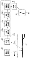
- FIG. 10 is a diagram showing spectral characteristics for explaining a case where three narrow-band light spectral image signals e1, e2, and e3 are estimated from three wide-band light image signals B, G, and R.
- the three broadband lights B, G, and R in FIG. 10 are obtained by the color filter of the image sensor 2A, and the image signals of the three broadband lights B, G, and R are input to the spectral estimation unit 101c.
- the spectral estimation unit 101c estimates the spectral estimation image signals e1, e2, and e3 of the narrowband light from the image signals B, G, and R of the three broadband lights by spectral estimation processing. From spectral signals B, G, and R of broadband light having a wavelength band as shown in FIG. 10, spectral estimated image signal e1 of narrowband light near wavelength 600 nm, spectrally estimated image signal e2 of narrowband light near wavelength 630 nm, and A spectral estimation image signal e3 of narrowband light in the vicinity of a wavelength of 540 nm is obtained by spectral estimation processing.
- spectral estimation image signals e1 and e2 of two narrowband lights between the wavelength band R of the maximum value ACmax and the minimum value ACmin in FIG. 5, and spectral estimation image signals e3 of the narrowband light outside the wavelength band R and Is obtained by spectral estimation, and the spectral estimated image signals e1, e2, e3 are supplied to the band resolution processing unit 104.
- three spectral image signals e1, e2, e3 may be obtained by spectral estimation processing from image signals of two broadband lights out of the three broadband lights, for example, image signals of the broadband lights G, R. .
- three (or two) broadband light image signals are not obtained by using the color filter of the color image sensor, but the light source device obtains an image signal having spectral characteristics as shown in FIG.
- the return light of the three (or two) illumination lights generated by arranging the first group of filters having the sensitivity characteristics on the optical path may be applied to the monochrome image pickup device to obtain it.
- the spectral estimation unit 101c generates and outputs three spectral estimation image signals e1, e2, and e3 by spectral estimation processing based on at least two imaging signals of return light from the subject. Furthermore, the spectral estimation unit 101c also performs spectral estimation processing on the spectral estimation image signal e3 corresponding to the return light based on the irradiation of illumination light that can be transmitted by a predetermined distance from the surface layer portion of the subject based on the at least two imaging signals. Generates and outputs. As described above, the processes in the band separation processing unit 104, the enhancement processing unit 101a, and the color conversion processing unit 101b are the same as those in the first embodiment. Therefore, the effect similar to that of the endoscope apparatus 1 described above can be obtained also by the endoscope apparatus 1A of the present embodiment.
- a modified example of spectral estimation will be described.
- a plurality of narrowband light spectral image signals are estimated from a plurality of wideband light image signals.
- the present invention is not limited to this method, and the following method may be used.
- the first method is to estimate three spectral image signals from two wideband light image signals and one narrowband light image signal. Since an image signal of narrowband light is used, the accuracy of spectral estimation can be increased.
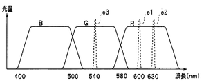
- FIG. 11 is a diagram showing spectral characteristics for explaining a case where three narrowband light spectral image signals are estimated from two wideband light image signals and one narrowband light image signal.
- B and G are broadband light
- R is narrowband light.
- three spectral estimated image signals e1, e2, and e3 are estimated from the two broadband light image signals B and G and one narrowband light image signal Rn.
- Three image signals of two broadband lights B and G and one narrowband light Rn may be obtained by a color filter of the image sensor 2A having spectral characteristics as shown in FIG.
- a return filter of three illumination lights that is, illumination lights of two broadband lights B and G and one narrowband light Rn
- You may try to get it.
- three image signals of two broadband light and one narrowband light may be obtained by the color filter of the image sensor 2A, or the light source device emits two or more illumination lights.
- the wavelength band of at least one illumination light (Rn) of the two or more illumination lights may be narrower than the wavelength bands of the other illumination lights (B, G).
- the spectral estimation unit 101c estimates the spectral estimation image signals e1, e2, and e3 of the three narrowband lights from the image signals Rn of the two broadband lights B and G and the image signal Rn of the single narrowband light by spectral estimation processing. . From two wideband light B and G image signals having a wavelength band as shown in FIG. 11 and one narrowband light image signal Rn, a spectrally estimated image signal e1 of narrowband light near a wavelength of 600 nm, a wavelength near 630 nm. A spectral estimated image signal e2 of narrowband light and a spectral image signal e3 of narrowband light near a wavelength of 540 nm are estimated.
- three spectral estimation image signals e1, e2, and e3 are obtained by spectral estimation processing from one broadband light image signal (eg, broadband signal G image signal) and one narrowband light Rn image signal. May be.
- one narrowband light Rn includes narrowband light near a wavelength of 600 nm, but may include narrowband light near a wavelength of 630 nm. Furthermore, one narrowband light Rn may not include a narrowband light near a wavelength of 600 nm or a narrowband light near a wavelength of 630 nm as shown by a one-dot chain line in FIG. Further, the three spectral estimation image signals e1, e2, e3 may be estimated from one wideband light image signal and two narrowband light image signals.
- three spectral image signals e1, e2, and e3 may be estimated from four or more narrowband light image signals.
- the estimation of three spectral estimation image signals from four or more narrowband light image signals is more effective than the estimation of three narrowband light image signals from three narrowband light image signals.
- the estimation accuracy is improved. Therefore, three spectral estimation image signals e1, e21, e31 may be obtained by spectral estimation processing from four or more narrowband light image signals, for example, image signals of narrowband light Bn, Gn, Rn.
- FIG. 12 is a diagram for explaining the flow of processing for an image obtained from the image sensor 2 in the image processing unit 101A of the present embodiment.
- three images that is, first to third image signals P1, P2, and P3 are input from the image sensor 2 to the spectral estimation unit 101c.
- the spectral estimation unit 101c estimates and generates three spectral estimation image signals e1, e2, and e3 from the input two or three image signals.
- the band resolution processing unit 104 performs band resolution processing on one spectral image signal e1.
- the enhancement processing unit 101a performs enhancement processing on the low spatial frequency band image signal (band image signal P1 (1) in FIG. 12) obtained by the band resolution processing.
- the spectral estimation unit 101c generates and outputs a spectral estimation image signal e1 as a first image signal by spectral estimation processing based on at least two imaging signals of return light from the subject, and performs band resolution processing.
- the unit 104 decomposes the spectral estimation image signal e1.
- the color conversion processing unit 101b performs channel assignment on the second spectral estimated image signal e2, the third spectral estimated image signal e3, and the enhanced corrected image signal BEP1 ( ⁇ 1) obtained by the enhancement process. A color conversion process is performed and output to the observation monitor 5.
- the two narrowband lights for example, illumination of narrowband light Gn near a wavelength of 540 nm and narrowband light Rn near a wavelength of 600 nm is irradiated, and the wavelength of the obtained two image signals Gn and Rn A spectral estimation image signal e2 of narrowband light around 630 nm is obtained by spectral estimation. Then, the spectral estimation image signal e2 is subjected to enhancement processing, a realistic image signal of the narrowband light Gn near the wavelength of 540 nm and the narrowband light Rn near the wavelength of 600 nm, and the spectral estimation image signal e2 subjected to the enhancement processing, You may make it display an image using.
- the color filter provided on the surface of the image sensor has been described as an example of an RGB system, but the color filter may be a complementary color system.
- a relatively thick blood vessel in a relatively deep part of the biological mucous membrane is enhanced and displayed on the screen of the observation monitor 5. Therefore, the surgeon can confirm a relatively thick blood vessel and perform a desired treatment such as ESD.
- the endoscope apparatus 1A described above can display blood vessels in a portion close to the surface layer of the biological mucous membrane using the third spectral estimation image signal e3, the state of the capillary blood vessels, for example, capillary It can also be used for diagnosis of living tissues, for example, diagnosis of the presence of cancer, range diagnosis for identifying the range of cancer, and differential diagnosis for judging benign or malignant diseased areas from the degree of concentration or dispersion of blood vessels it can. Furthermore, it is also possible to perform a depth of diagnosis that is conscious of deeper blood vessels. In addition to the third spectral estimation image signal e3, the fourth and fifth images obtained by spectral estimation may also be used to perform color conversion processing and display on the observation monitor 5. .
- the wavelength of the second spectral estimation signal e2 shown in FIGS. 10 to 11 is light in a wavelength band longer than the minimum value ACmin (here, the absorption coefficient at a wavelength of 730 nm) of the absorption characteristic of hemoglobin in FIG. Also good.
- the wavelength of the second spectral estimation signal e2 is a wavelength band in which the absorption coefficient is lower than the wavelength of the first spectral estimation signal e1 and the scattering characteristics of the living tissue are suppressed, for example, 740 nm, Even when 770 nm, 805 nm, 810 nm, 850 nm, 870 nm, 880 nm, 910 nm, 940 nm, 1020 nm, and 1300 nm can be used, the same effect as described above can be obtained (for example, the wavelength of the second spectral estimation signal e 2 is 740 nm).
- the wavelength of the first spectral estimation signal e1 is set to any wavelength of 576 nm or more and at least 630 nm or less).
- the biological tissue is actually irradiated with at least one narrowband light as illumination light, and the above-described band decomposition processing is performed on the image of the return light, and the band decomposition processing is performed.
- the enhancement processing is performed on at least one band image signal, and in the second embodiment, the image of the return light of each narrow band light is obtained by so-called spectroscopic estimation without actually irradiating the biological tissue with at least one narrow band light.
- the band resolution processing and the enhancement processing as described above are performed on the spectral estimation image signal of each wavelength obtained by obtaining the spectral estimation, but in the third embodiment, at least two narrow narrowing processings are performed.
- Band resolution processing is performed on the image signal of the return light of the actual illumination light of the band light (or the image signal of the return light of the actual illumination light of one narrow band light and the spectral estimation image signal obtained by the spectral estimation).
- bandwidth Performs spectral estimation process using at least two band image signal obtained by the solution treatment, enhancement processing is performed on the spectral estimation image signal obtained by the spectral estimation.
- the configuration of the endoscope apparatus 1B of the present embodiment is the same as that of the endoscope apparatus 1 shown in FIG. 1, but the configuration of the rotary filter 14A of the present embodiment is different.
- FIG. 13 is a diagram showing a configuration of the rotary filter 14A of the present embodiment. As shown in FIG.
- the rotary filter 14A is a second filter group including three filters 14-600, 14-630, and 14-540 that transmit the light of the three predetermined narrow band wavelengths shown in FIG. Only have.
- the frame-sequential return light is received by the monochrome image sensor 2.
- the rotary filter 14 ⁇ / b> A may use an RGB filter unit that constitutes a filter set for outputting frame-sequential light having spectral characteristics for normal light observation.
- FIG. 14 is a diagram for explaining the overall processing flow in the special light observation mode according to the present embodiment.
- the image processing unit 101B includes a band separation processing unit 104, an enhancement processing unit 101a, a color conversion processing unit 101b, and a spectral estimation unit 101c.
- the band decomposition processing unit 104 performs band decomposition processing on two image signals, it includes two band decomposition processing units 104A and 104B (FIG. 15).
- the spectral estimation unit 101c is a spectral estimation unit or a spectral estimation unit that generates a spectral estimation image signal by spectral estimation processing based on at least two input signals.
- at least two band images obtained by band decomposition processing are used.
- At least one spectral estimation image signal e is generated from the signal, and enhancement processing is performed on the spectral estimation image signal e.
- the band resolution processing by the two band resolution processing units is performed on the image signal P1 near the wavelength of 600 nm and the second image signal P2 near the wavelength of 630 nm. Then, for each of the two image signals P1 and P2, spectral estimation processing is performed using the low spatial frequency band image signals P1 (1) and P2 (1) obtained by the band decomposition processing.
- the enhancement processing unit 101a performs enhancement processing on the spectral estimation image signal e1 obtained by the spectral estimation processing.
- FIG. 15 is a diagram for explaining a flow of processing for an image obtained from the image sensor 2 in the image processing unit 101B according to the present embodiment.
- a first image signal P1 near a wavelength of 600 nm a second image signal P2 near a wavelength of 630 nm
- a third image signal P3 near a wavelength of 540 nm are obtained. Is input to the image processing unit 101B.
- the first image signal P1 and the second image signal P2 are subjected to band decomposition processing by the band decomposition processing units 104A and 104B, respectively.
- the band resolution processing units 104A and 104B have the same configuration as the band resolution processing unit 104 described above.
- N band image signals P1 (1), P1 (2),... P1 (N) are generated for the first image signal P1 by the band resolution processing, and the second image signal P2 is also calculated.
- N band image signals P2 (1), P2 (2),... P2 (N) are generated.
- the band resolution processing units 104A and 104B both generate the same number of band image signals, but may generate different numbers of band image signals.
- the spatial frequency is lowest in fr1 and higher in order from fr2 to frN. Therefore, of the N band image signals P1 (1), P1 (2),... P1 (N), the band image signal P1 (1) is the image signal with the lowest spatial frequency, and the N bands Of the image signals P2 (1), P2 (2),... P2 (N), the band image signal P2 (1) is the image signal having the lowest spatial frequency (for example, near P1 (1) and P2 ( 1)
- the band image signal in the vicinity has information on a biological structure such as a thicker deep blood vessel, etc.
- the band image signals in the vicinity of P1 (N) and P2 (N) have thinner mucosal surface layers. Information on surface irregularities such as blood vessels and glandular structures).
- the spectral estimation unit 101c has a low spatial frequency band image signal (here, the lowest spatial frequency band image signal P1 (1)) among the plurality of band image signals generated by the band resolution processing units 104A and 104B. Based on P2 (1)), the spectral estimated image signal e1 of the first image signal P1 near the wavelength of 600 nm is estimated and generated.
- the enhancement processing unit 101a performs enhancement processing such as multiplication of the spectral estimation image signal e1 by a gain coefficient, and the enhancement correction image signal BEP1 ( ⁇ 1) is output to the color conversion processing unit 101b.
- the color conversion processing unit 101b applies the second image signal P2 near the wavelength of 630 nm, the third image signal P3 near the wavelength of 540 nm, and the enhanced corrected image signal BEP1 ( ⁇ 1) obtained by the enhancement process. Color conversion processing by channel assignment is performed and output to the observation monitor 5.
- the processing in the enhancement processing unit 101a and the color conversion processing unit 101b is the same as that in the first embodiment.
- the band resolution processing units 104A and 104B have the spectral wavelength peak wavelength between the wavelength band including the maximum value ACmax and the wavelength band of the minimum value ACmin in the absorption characteristics of the living tissue after imaging by the imaging device 2.
- the second image signal P2 having the above is decomposed into a plurality of spatial frequency bands.
- the spectral estimation unit 101c generates a band image signal having a low spatial frequency among the plurality of band image signals generated by the band resolution processing units 104A and 104B for each of the first image signal P1 and the second image signal P2.
- the spectral estimation process is performed as at least two input signals.
- the enhancement processing unit 101a performs enhancement processing using the spectral estimation image signal e1 obtained by the spectral estimation processing of the spectral estimation unit 101c as a predetermined first band image signal.
- the band resolution is performed on the image signal P1 near the wavelength of 600 nm and the second image signal near the wavelength of 630 nm, which are the image signals of the return light of the actual illumination light of the two narrowband lights.
- processing is performed, at least one of the two image signals may be a spectral estimation image signal obtained by spectral estimation.
- the obtained spectral estimated image signal e1 may be subjected to band decomposition processing.
- spectral estimation is performed from the first image signal P1 and the third image signal P3 instead of the second image signal P2.
- the obtained spectral estimation image signal e2 may be subjected to band decomposition processing.
- spectral estimation is performed using two band images having a low spatial frequency from among a plurality of band image signals obtained by band resolution processing, and the comparison is performed.
- a spectrally estimated image of a thick blood vessel is obtained, and enhancement processing is performed on the spectrally estimated image.
- the three narrowband light (or broadband light) in FIG. 15 may be obtained by the color filter of the image sensor 2A. That is, three narrow band lights (or broadband lights) may be obtained by using the light source device 4A as described in the second embodiment and the color filter of the image sensor 2A.
- the same effects as those of the endoscope apparatuses 1 and 1A described above can be obtained.
- the color filter provided on the surface of the image sensor the RGB filter has been described as an example.
- the color filter may be a complementary color filter.
- the wavelength ⁇ 2 of the second image signal P2 shown in FIG. 15 may be light in a wavelength band longer than the minimum value ACmin (here, the absorption coefficient at a wavelength of 730 nm) of the absorption characteristic of hemoglobin in FIG.
- the wavelength of the second image signal P2 is a wavelength band in which the absorption coefficient is lower than the wavelength of the first image signal P1 and the scattering characteristics of the living tissue are suppressed, for example, 740 nm, 770 nm, Even when 805 nm, 810 nm, 850 nm, 870 nm, 880 nm, 910 nm, 940 nm, 1020 nm, and 1300 nm are used, the same effect as described above can be obtained (for example, the wavelength of the second image signal P2 is 740 nm to 1300 nm) When setting to any wavelength, the wavelength of the first image signal P1 is set to any wavelength of 576 nm or more and at least 630 nm or less).
- a relatively thick blood vessel in a relatively deep part of the biological mucous membrane is enhanced and displayed on the screen of the observation monitor 5. Therefore, the surgeon can confirm a relatively thick blood vessel and perform a desired treatment such as ESD.
- the endoscope apparatus 1A described above can display blood vessels in a portion close to the surface layer of the biological mucous membrane using the third image signal P3 near the wavelength of 540 nm, for example, the state of capillary blood vessels, for example, , Based on the degree of concentration or dispersion of capillaries, it can also be used for diagnosis of living tissues, for example, diagnosis of cancer presence, range diagnosis for identifying the range of cancer, and differential diagnosis for judging benign or malignant diseased areas. be able to. Furthermore, it is also possible to perform a depth of diagnosis that is conscious of deeper blood vessels.
- Modification 1 the light absorption characteristic of venous blood is taken as an example, and two narrowband lights are selected based on the characteristic, but the light absorption characteristic of arterial blood or Based on the light absorption characteristics of blood that combines both venous blood and arterial blood, at least two narrowband lights as described above may be selected.
- the wavelength of each of the first narrowband light NL1 and the second narrowband light NL2 is 600 nm.
- the light in the vicinity and the light in the vicinity of 630 nm are used.
- the wavelengths of the first narrowband light NL1 and the second narrowband light NL2 are preferably wavelengths in the range of 580 to 620 nm, respectively.
- the wavelengths of the first narrowband light NL1 and the second narrowband light NL2 are each 600 nm.
- the light is not limited to light in the vicinity and light in the vicinity of a wavelength of 630 nm, and light of any wavelength may be used.
- the wavelengths of the first narrowband light NL1 and the second narrowband light NL2 respectively, the light near the wavelength 610 nm and the light near the wavelength 645 nm, or the light near the wavelength 630 nm and the light near the wavelength 660 nm are used. Also good.
- the wavelength of the third narrowband light NL3 is not limited to this.
- the wavelength of the third narrowband light NL3 light having a wavelength near 415 nm or light having a wavelength of 460 nm shorter than the wavelength 540 nm may be used.
- light having a wavelength of about 415 nm or light having a wavelength of 460 nm, which is shorter than light having a wavelength of about 540 nm is desirable.
- Modification 4 In the light source device of each embodiment and each modification described above (including the modification of each embodiment), it has been described that a lamp, LED, LD, or the like of a heat source is used, but other means are used. Also good. For example, a tunable laser may be used as the light source means or the light source unit, or broadband light may be generated by exciting a phosphor with an LED or LD, and the light may be used.
- Modification 5 In the endoscope apparatus of each embodiment and each modification described above (including the modification of each embodiment), when radiating narrowband light, for example, narrowband light near a wavelength of 600 nm is generated by a laser, Narrow band light around a wavelength of 630 nm may be generated by an LED. When laser light is used, noise in the depth direction can be reduced. Further, narrow band light near a wavelength of 600 nm may be generated by an LED, and narrow band light near a wavelength of 630 nm may be generated by a laser.
- FIG. 16 is a diagram showing light absorption characteristics of venous blood for explaining the sixth modification.
- one is a narrowband light NL1 near a wavelength of 600 nm, a narrowband light NL2 near a wavelength 630 nm, and a narrowband light NL3 near a wavelength 540 nm.
- the combination of light is enhanced, and the other is a combination of three narrowband lights, a narrowband light NL12 near 650 nm, a narrowband NL22 near 680 nm, and a narrowband NL3 near 540 nm.
- Which combination is selected can be selected by the user. For example, by selecting a mode, the user can select which combination is used for display.
- a combination of a narrowband light near a wavelength of 615 nm, a narrowband light near a wavelength of 645 nm, and a narrowband light NL3 near a wavelength of 540 nm, a narrowband light near a wavelength of 630 nm and a narrowband near a wavelength of 660 nm may be used.
- the wavelength used is shifted to the longer wavelength side compared to the first combination, so that a deeper image is emphasized. Therefore, if the surgeon wants to emphasize deeper blood vessels, or if blood, bile, urine, etc. are attached to the mucosal surface of the living body, the desired blood vessel is emphasized by selecting the second combination. It can be displayed.
- the enhancement processing for two or more combinations can be performed by increasing the number of combinations of rotation filters in the light source device or by increasing the number of spectral estimation image signals estimated by the spectral estimation processing.
- a combination of narrowband light wavelengths when a relatively shallow blood vessel is highlighted from the mucosal surface, a combination of a wavelength near 580 nm, a wavelength near 630 nm, a wavelength 540 nm, a wavelength 590 nm, a wavelength 630 nm, and a wavelength 540 nm It is preferable to have two of these combinations.
- wavelengths of narrowband light when a blood vessel deeper from the mucosal surface or a blood vessel under the mucous membrane under the blood or the like can be highlighted, a wavelength near 600 nm, a wavelength near 630 nm, and a wavelength near 540 nm And a combination of the vicinity of wavelength 650 nm, the vicinity of wavelength 680 nm, and the vicinity of wavelength 540 nm.
- a narrow band light near a wavelength of 600 nm a narrow band light near a wavelength of 630 nm
- a first combination near a wavelength of 540 nm a narrow band light near a wavelength of 650 nm
- a narrow band light near a wavelength of 680 nm a wavelength of 540 nm.
- the surgeon can select a longer wavelength side combination (for example, near a wavelength of 650 nm) when the concentration of blood or the like adhering to the mucosal surface of the living body is high. And a combination of a wavelength of around 680 nm and a wavelength of around 540 nm), and if the blood vessel is in a relatively shallow part, or if the concentration of blood adhering to the mucosal surface of the living body is low, the shorter wavelength
- a combination on the side for example, a combination of a wavelength near 590 nm, a wavelength near 630 nm, and a wavelength 540 nm
- a desired blood vessel can be highlighted.
- the narrowband light near a wavelength of 600 nm is fixed, and the other narrowband light can be arbitrarily set from a wavelength near 630 nm to near 730 nm. You may be able to do it.
- the other narrow-band light near the wavelength of 730 nm may be fixed, and the variable from the wavelength near 590 nm to the narrow-band light near 620 nm may be set arbitrarily.
- the narrowband light near 600 nm may be fixed, and the other narrowband light may be arbitrarily set in a wavelength band of 730 nm or more. In this way, by fixing one of the wavelength differences between the two narrow-band lights and making the other variable, it is possible to display a blood vessel in a desired region more emphasized.
- Modification 7 In each of the above-described embodiments and modifications (including the modifications of each embodiment), three images are obtained and a narrowband image is displayed on the observation monitor 5.
- a display image may be generated by appropriately selecting from four images so that an eye image is obtained.
- the endoscope apparatus has a narrow-band light observation mode in addition to the normal light observation mode, and the operator performs various treatments by switching from the normal light observation mode to the narrow-band light observation mode when necessary.
- a display image in each observation mode can be easily obtained.
- a fourth image is obtained using a light source device that can further irradiate blue narrow-band light (or broadband light) having a wavelength shorter than 540 nm.
- the light source device illuminates a first combination of light of the fourth wavelength and narrowband light near the wavelength of 600 nm, and a second combination of narrowband light near the wavelength of 540 nm and narrowband light near the wavelength of 630 nm. Illuminate the subject alternately with light. It is to be noted that illumination light of a combination of the fourth wavelength light, the narrow band light near the wavelength of 540 nm and the narrow band light near the wavelength of 600 nm and the illumination light of the narrow band light near the wavelength of 630 nm are alternately irradiated on the subject. It may be.
- the return light of each illumination light is received by an image sensor having an RGB color filter.
- the return light of the fourth wavelength is imaged in the B band of the color filter, and the return light of the narrow band light near the wavelength of 600 nm is imaged in the R band.
- the color filter of the image sensor may be a complementary color type.
- the image sensor may be a monochrome image sensor.
- the normal image for the normal light observation mode includes four light beams of the fourth wavelength, the narrow band light near the wavelength 540 nm, the narrow band light near the wavelength 600 nm, and the narrow band light near the wavelength 630 nm. It is generated using an image of the return light.
- the first narrowband light image is assigned to the B and G channels
- the fourth wavelength light image signal is assigned to the R channel
- the narrowband light image signal near the wavelength of 540 nm is assigned to the R channel.
- the image is generated using two images of light of four wavelengths and narrowband light near a wavelength of 540 nm.
- a second narrowband light image is generated using three images of a narrowband light having a wavelength near 540 nm, a narrowband light having a wavelength near 600 nm, and a narrowband light having a wavelength near 630 nm. Note that an image signal of narrowband light having a wavelength near 600 nm is subjected to enhancement processing.
- a normal image for normal light observation and a narrow band light image for narrow band light observation can be displayed simultaneously, or a normal image and a narrow band light image can be superimposed and displayed.
- the normal light image and the first narrowband light image (or the second narrowband light image) are displayed in parallel, or the first narrowband light image and the second narrowband light image are displayed in parallel.
- an image signal of four wavelengths of light is used as a B channel, an image signal of a narrow band of light near a wavelength of 540 nm and an image signal of a narrow band of light near a wavelength of 600 nm as a G channel, and an image signal of a narrow band of light near a wavelength of 600 nm (or (Narrowband light image signal near 600 nm wavelength and Narrowband light image signal near 630 nm wavelength) are assigned to the R channel, and the superposition of the blood vessel information in the deep part added to the normal image generates an image and the observation monitor 5 can also be displayed.
- the image signal of the fourth wavelength light is set to the B channel
- the image signal of the fourth wavelength light and the image signal of the narrow band light near the wavelength of 600 nm are set to the G channel
- the image signal of the narrow band light near the wavelength of 600 nm is set.
- Or narrowband light image signal near wavelength 600 nm and narrowband light image signal near wavelength 630 nm are assigned to the R channel to generate an image that emphasizes both the blood vessels in the surface layer and the deep blood vessels. It can also be displayed on the observation monitor 5.
- the image signal of the fourth wavelength may be generated by spectral estimation.
- a normal image and a narrowband light image can be displayed in parallel or superimposed.
- the blood vessels in the deep mucosa are clearly displayed without the complicated operation of drug administration.
- a possible endoscopic device can be provided.
Landscapes
- Health & Medical Sciences (AREA)
- Life Sciences & Earth Sciences (AREA)
- Surgery (AREA)
- Engineering & Computer Science (AREA)
- Physics & Mathematics (AREA)
- Optics & Photonics (AREA)
- Biomedical Technology (AREA)
- Molecular Biology (AREA)
- Pathology (AREA)
- Nuclear Medicine, Radiotherapy & Molecular Imaging (AREA)
- Biophysics (AREA)
- Heart & Thoracic Surgery (AREA)
- Medical Informatics (AREA)
- Radiology & Medical Imaging (AREA)
- Animal Behavior & Ethology (AREA)
- General Health & Medical Sciences (AREA)
- Public Health (AREA)
- Veterinary Medicine (AREA)
- Microelectronics & Electronic Packaging (AREA)
- Signal Processing (AREA)
- Endoscopes (AREA)
- Instruments For Viewing The Inside Of Hollow Bodies (AREA)
Abstract
内視鏡装置1は、被検体に対し、所定の波長帯域を有する少なくとも1つ以上の照明光を照射する光源装置4と、光源装置4の照射に基づく被検体からの戻り光を撮像する撮像素子2と、ビデオオプロセッサ7と、観察モニタ5とを含む。ビデオプロセッサ7の帯域分解処理部104は、撮像素子2による撮像後、生体組織の吸収特性において極大値を含む波長帯域から極小値における波長帯域の間で、分光特性のピーク波長を有する第1の画像信号P1に対して、複数の空間周波数帯域に分解処理を行う。ビデオプロセッサ7の強調処理部101aは、分解処理されて得られた複数の帯域画像信号のうちの、最も空間周波数の低い帯域画像信号に基づいて、強調処理を行い強調補正した画像信号を生成する。
Description
本発明は、内視鏡装置に関し、特に、被検体内部の血管を表示することが可能な内視鏡装置に関する。
従来より、医療分野において、内視鏡を用いた低侵襲な各種検査や手術が行われている。術者は、体腔内に内視鏡を挿入し、内視鏡挿入部の先端部に設けられた撮像装置により撮像された被写体を観察し、必要に応じて処置具チャンネル内に挿通した処置具を用いて病変部に対して処置をすることができる。内視鏡を用いた手術は、開腹等をすることがないため、患者の身体的負担が少ないというメリットがある。
内視鏡装置は、内視鏡と、内視鏡に接続された画像処理装置と、観察モニタとを含んで構成される。内視鏡挿入部の先端部に設けられた撮像素子により病変部が撮像され、そのモニタにその画像が表示される。術者は、そのモニタに表示された画像を見ながら、診断あるいは必要な処置を行うことができる。
また、内視鏡装置には、白色光を用いた通常光観察だけでなく、内部の血管を観察するために、赤外光等の特殊光を用いた特殊光観察ができるものもある。
赤外内視鏡装置の場合、例えば、波長805nm付近の近赤外光に吸収ピークの特性を持つインドシアニングリーン(ICG)が薬剤として患者の血中に注入される。そして、光源装置から波長805nm付近及び930nm付近の赤外光を時分割で被写体に照射する。CCDで撮像された被写体像の信号は、赤外内視鏡装置のプロセッサに入力される。例えば、日本特開2000-41942号公報に開示のように、このような赤外内視鏡装置に関しては、プロセッサは、波長805nm付近の像を緑色信号(G)に、波長930nm付近の像を青色信号(B)に、割り当てて、モニタに出力する装置が、提案されている。ICGにより吸収の多い画像805nm付近の赤外光の像を、緑色に割り当てているので、術者は、ICG投与時の赤外画像をコントラスト良く観察できる。
赤外内視鏡装置の場合、例えば、波長805nm付近の近赤外光に吸収ピークの特性を持つインドシアニングリーン(ICG)が薬剤として患者の血中に注入される。そして、光源装置から波長805nm付近及び930nm付近の赤外光を時分割で被写体に照射する。CCDで撮像された被写体像の信号は、赤外内視鏡装置のプロセッサに入力される。例えば、日本特開2000-41942号公報に開示のように、このような赤外内視鏡装置に関しては、プロセッサは、波長805nm付近の像を緑色信号(G)に、波長930nm付近の像を青色信号(B)に、割り当てて、モニタに出力する装置が、提案されている。ICGにより吸収の多い画像805nm付近の赤外光の像を、緑色に割り当てているので、術者は、ICG投与時の赤外画像をコントラスト良く観察できる。
例えば、内視鏡を用いて、病変部の存在する粘膜下層を切開し、剥離する粘膜下層剥離術(以下、ESD(Endoscopic Submucosal Dissection)という)等では、電気メスなどによって粘膜中の比較的太い血管を切ってしまわないように、術者は、そのような血管の位置を確認して、切開等の処置を行う。重度の出血を起こすおそれのある血管は、粘膜下層から固有筋層を走行している。ESD等の手技において重度の出血が発生した場合、その都度止血作業をしなければならないので、手術時間が長くなってしまう。
しかし、上述した赤外内視鏡装置を用いて、血管の位置を確認するためには、上述したように、ICG等の薬剤を静脈注射するという煩雑な作業が必要となる。
また、上記赤外内視鏡装置の場合、照明光の波長が近赤外光の波長であるため、画像における血管がぼやけてしまうという問題もある。
また、上記赤外内視鏡装置の場合、照明光の波長が近赤外光の波長であるため、画像における血管がぼやけてしまうという問題もある。
そこで、本発明は、上述した問題に鑑みて成されたものであり、薬剤投与という煩雑な作業をすることなく、かつ粘膜深部の血管を明瞭に表示可能な内視鏡装置を提供することを目的とする。
本発明の一態様によれば、被検体に対し、所定の波長帯域を有する少なくとも1つ以上の照明光を照射する照明部と、前記照明部の照射に基づく前記被検体からの戻り光を撮像する撮像部と、前記撮像部による撮像後、生体組織の吸収特性において極大値を含む波長帯域から極小値における波長帯域の間で、分光特性のピーク波長を有する第1の画像信号に対して、複数の空間周波数帯域に分解処理を行う帯域分解処理部と、前記帯域分解処理部により分解処理されて得られた複数の帯域画像信号のうちの、所定の第1の帯域画像信号に基づいて、強調処理を行い強調補正した画像信号を生成する画像処理部と、前記強調補正した画像信号を表示する表示部と、を備える内視鏡装置を提供することができる。
以下、図面を参照して本発明の実施の形態を説明する。
(第1の実施の形態)
(内視鏡装置の構成)
以下、図面を参照して本発明の実施の形態を説明する。
まず、本実施の形態に関わる内視鏡装置の構成を説明する。図1は、本実施の形態に関わる内視鏡装置の構成を示す構成図である。
(第1の実施の形態)
(内視鏡装置の構成)
以下、図面を参照して本発明の実施の形態を説明する。
まず、本実施の形態に関わる内視鏡装置の構成を説明する。図1は、本実施の形態に関わる内視鏡装置の構成を示す構成図である。
図1に示すように、本実施の形態の内視鏡装置1は、体腔内に挿入し体腔内組織を撮像する生体画像情報取得手段あるいは生体画像情報取得部として撮像素子であるCCD2を有する電子内視鏡3と、電子内視鏡3に照明光を供給する光源装置4と、電子内視鏡3のCCD2からの撮像信号を信号処理して内視鏡画像を観察モニタ5に表示するビデオプロセッサ7とから構成される。内視鏡装置1は、通常光観察モードと狭帯域光観察モードの2つのモードを有する。なお、以下の説明では、内視鏡装置1の通常光観察モードは、従来の通常光観察モードと同じであるので、通常光観察モードの構成の説明は省略し、主として狭帯域光観察モードについて説明する。
CCD2は、被検体に照射された照明光の戻り光を受光して被検体を撮像する撮像部あるいは撮像手段を構成する。
照明手段あるいは照明部としての光源装置4は、照明光(白色光)を発光するキセノンランプ11と、白色光の熱線を遮断する熱線カットフィルタ12と、熱線カットフィルタ12を介した白色光の光量を制御する絞り装置13と、照明光を面順次光にする帯域制限手段あるいは帯域制限部としての回転フィルタ14と、電子内視鏡3内に配設されたライトガイド15の入射面に回転フィルタ14を介した面順次光を集光させる集光レンズ16と、回転フィルタ14の回転を制御する制御回路17とを備えて構成される。キセノンランプ11、回転フィルタ14及びライトガイド15が、被検体に対して照明光を照明する照射部あるいは照射手段を構成する。
照明手段あるいは照明部としての光源装置4は、照明光(白色光)を発光するキセノンランプ11と、白色光の熱線を遮断する熱線カットフィルタ12と、熱線カットフィルタ12を介した白色光の光量を制御する絞り装置13と、照明光を面順次光にする帯域制限手段あるいは帯域制限部としての回転フィルタ14と、電子内視鏡3内に配設されたライトガイド15の入射面に回転フィルタ14を介した面順次光を集光させる集光レンズ16と、回転フィルタ14の回転を制御する制御回路17とを備えて構成される。キセノンランプ11、回転フィルタ14及びライトガイド15が、被検体に対して照明光を照明する照射部あるいは照射手段を構成する。
図2は、回転フィルタ14の構成を示す図である。回転フィルタ14は、光源であるキセノンランプ11からの光を透過するフィルタである。波長帯域制限部あるいは波長帯域制限手段としての回転フィルタ14は、図2に示すように、円盤状に構成され、中心を回転軸とした構造となっており、2つのフィルタ群を有している。回転フィルタ14の外周側には、周方向に沿って、通常光観察用の分光特性の面順次光を出力するためのフィルタ組を構成するR(赤)フィルタ部14r,G(緑)フィルタ部14g,B(青)フィルタ部14bが、第1のフィルタ群として、配置されている。
回転14の内周側には、周方向に沿って、3つの所定の狭帯域波長の光を透過させる3つのフィルタ14-600,14-630,14-540が、第2のフィルタ群として、配置されている。
フィルタ14-600は、狭帯域光として、波長600nm(λ1)付近の光を透過させるように構成されている。フィルタ14-630は、狭帯域光として、波長630nm(λ2)付近の光を透過させるように構成されている。フィルタ14-540は、狭帯域光として、波長540nm(λ3)付近の光を透過させるように構成されている。
ここで「付近」とは、波長600nm付近の場合は、中心波長が600nmで、波長600nmを中心に、幅が、例えば20nm(すなわち波長600nmの前後である波長590nmから610nm)の範囲の分布を有する狭帯域光であることを意味する。他の波長である、波長630nm、及び後述する波長540nmについても同様である。
回転フィルタ14は、照明光の出射部であるキセノンランプ11からCCD2の撮像面に至る光路上に配置され、各モードにおいて、照明光の複数の波長帯域のうち少なくとも1つ(ここでは3つ)の波長帯域を狭めるように制限する。
そして、制御回路17は、回転フィルタ14を回転させるためのモータ18を制御して、回転フィルタ14の回転を制御する。
モータ18には、ラック19aが接続され、ピニオン19bには、図示しないモータが接続され、ラック19aは、ピニオン19bに螺合するように取り付けられている。制御回路17は、ピニオン19bに接続されたモータの回転を制御することによって、回転フィルタ14を矢印dで示す方向に移動することができる。よって、制御回路17は、後述するユーザによるモード切替操作に応じて、通常光観察モードのときは第1のフィルタ群を、狭帯域光観察モードのときは第2のフィルタ群を、光路上に位置させるようにピニオン19bに接続されたモータを制御する。
なお、キセノンランプ11、絞り装置13、回転フィルタモータ18、及びピニオン19bに接続されたモータ(図示せず)には電源部10より電力が供給される。
なお、キセノンランプ11、絞り装置13、回転フィルタモータ18、及びピニオン19bに接続されたモータ(図示せず)には電源部10より電力が供給される。
よって、光源装置4は 狭帯域光観察モードのとき、被検体に対し、所定の波長帯域を有する少なくとも1つ以上の照明光(ここでは、3つの狭帯域光)を照射する照明手段あるいは照明部を構成する。ここでは、3つの照明光のうち2つは、表層から1~2mmの深部の血管を強調表示するための狭帯域光であり、残りの1つは、被検体の表層部から所定の距離だけ、ここでは表層近傍の範囲だけ、透過可能な第3の照明光としての狭帯域光である。
ビデオプロセッサ7は、CCDドライバであるCCD駆動回路20、アンプ22、プロセス回路23、A/D変換器24、ホワイトバランス回路(以下、W.Bという)25、セレクタ100、画像処理部101、セレクタ102、γ補正回路26、拡大回路27、強調回路28、セレクタ29、同時化メモリ30、31,32、画像処理回路33、D/A変換器34,35,36、タイミングジェネレータ(以下、T.Gという)37、モード切替回路42、調光回路43、調光制御パラメータ切替回路44、制御回路200、及び、表示画像生成手段あるいは表示画像生成部としての合成回路201を備えて構成される。
CCD駆動回路20は、電子内視鏡3に設けられたCCD2を駆動し、回転フィルタ14の回転に同期した面順次の撮像信号をCCD2に出力させるものである。また、アンプ22は電子内視鏡3の先端に設けられている対物光学系21を介してCCD2により体腔内組織を撮像した面順次の撮像信号を増幅するものである。
プロセス回路23は、アンプ22を介した面順次の撮像信号に対して相関2重サンプリング及びノイズ除去等を行う。A/D変換器24は、プロセス回路23を経た面順次の撮像信号をデジタル信号の面順次の画像信号に変換する。
W.B25は、A/D変換器24によりデジタル化された面順次の画像信号に対して、例えば画像信号のG信号を基準に画像信号のR信号と画像信号のB信号の明るさが同等となるようにゲイン調整を行い、ホワイトバランス処理を実行する。
なお、W.B25におけるホワイトバランス調整は、波長600nm付近の狭帯域光の戻り光の輝度を基準に行われる。
セレクタ100は、W.B25からの面順次の画像信号を画像処理部101内の各部に振り分けて出力する。
なお、W.B25におけるホワイトバランス調整は、波長600nm付近の狭帯域光の戻り光の輝度を基準に行われる。
セレクタ100は、W.B25からの面順次の画像信号を画像処理部101内の各部に振り分けて出力する。
画像処理部101は、前記セレクタ100からの通常光観察用のRGBの画像信号又は狭帯域光観察用の3つの画像信号を、表示用の画像信号に変換する画像信号処理部あるいは画像信号処理手段である。画像処理部101は、モード信号に基づく制御回路200からの選択信号SSに応じて、通常光観察モード時及び狭帯域光観察モード時の画像信号を、セレクタ102へ出力する。
セレクタ102は、画像処理部101からの通常光観察用画像信号と狭帯域光観察用画像信号の面順次の画像信号をγ補正回路26及び合成回路201に順次出力する。
セレクタ102は、画像処理部101からの通常光観察用画像信号と狭帯域光観察用画像信号の面順次の画像信号をγ補正回路26及び合成回路201に順次出力する。
γ補正回路26は、セレクタ102あるいは合成回路201からの面順次の画像信号に対してγ補正処理を施す。拡大回路27は、γ補正回路26にてγ補正処理された面順次の画像信号を拡大処理する。強調回路28は、拡大回路27にて拡大処理された面順次の画像信号に輪郭強調処理を施す。セレクタ29及び同時化メモリ30、31,32は、強調回路28からの面順次の画像信号を同時化するためのものである。
画像処理回路33は、同時化メモリ30、31,32に格納された面順次の各画像信号を読み出し、動画色ずれ補正処理等を行う。D/A変換器34,35,36は、画像処理回路33からの画像信号を、RGBのアナログの映像信号に変換し観察モニタ5に出力する。T.G37は、光源装置4の制御回路17から、回転フィルタ14の回転に同期した同期信号を入力し、各種タイミング信号を上記ビデオプロセッサ7内の各回路に出力する。
また、電子内視鏡2には、通常光観察モード及び狭帯域光観察モードの切替のためのモード切替スイッチ41が設けられており、このモード切替スイッチ41の出力がビデオプロセッサ7内のモード切替回路42に出力されるようになっている。ビデオプロセッサ7のモード切替回路42は、制御信号を調光制御パラメータ切替回路44及び制御回路200に出力するようになっている。調光回路43は、調光制御パラメータ切替回路44からの調光制御パラメータ及びプロセス回路23を経た撮像信号に基づき、光源装置4の絞り装置13を制御し適正な明るさ制御を行うようになっている。
ビデオプロセッサ7内の各回路は、指定されたモードに応じた所定の処理を実行する。通常光観察モードと狭帯域光観察モードのそれぞれに応じた処理が実行されて、観察モニタ5には、通常光観察用画像あるいは狭帯域光観察画像が表示される。観察モニタ5は、後述するように、強調補正した画像信号を表示する表示手段あるいは表示部である。
(狭帯域光観察の全体の処理の流れ)
次に、本実施の形態における狭帯域光観察の全体の大まかな流れを簡単に説明する。
図3は、本実施の形態に関わる狭帯域光観察における全体の処理の流れを説明するための図である。
術者は、内視鏡の挿入部を体腔内に挿入し、通常光観察モード下で、内視鏡挿入部の先端部を病変部近傍に位置させる。術者は、処置対象の病変部を確認すると、粘膜下層から固有筋層を走行する、比較的太い、例えば直径が1~2mmの、深部の血管を観察するために、モード切替スイッチ41を操作して、内視鏡装置1を狭帯域光観察モードに切り替える。
次に、本実施の形態における狭帯域光観察の全体の大まかな流れを簡単に説明する。
図3は、本実施の形態に関わる狭帯域光観察における全体の処理の流れを説明するための図である。
術者は、内視鏡の挿入部を体腔内に挿入し、通常光観察モード下で、内視鏡挿入部の先端部を病変部近傍に位置させる。術者は、処置対象の病変部を確認すると、粘膜下層から固有筋層を走行する、比較的太い、例えば直径が1~2mmの、深部の血管を観察するために、モード切替スイッチ41を操作して、内視鏡装置1を狭帯域光観察モードに切り替える。
狭帯域光観察モード下では、内視鏡装置1の制御回路17は、第2のフィルタ群を透過した光を、光源装置4から出射するように、ピニオン19bに接続されたモータを制御して、回転フィルタ14の位置を移動させる。さらに、制御回路200も、狭帯域波長による観察のための画像処理を行うように、ビデオプロセッサ7内の各種回路を制御する。
図3に示すように、狭帯域光観察モードでは、照明光発生部51から、狭帯域波長の照明光が、内視鏡3の挿入部の先端部から出射され、粘膜層を透過して、粘膜下層及び固有筋層を走行する血管61に照射される。ここで、照明光発生部51は、光源装置4、回転フィルタ14、ライトガイド15等を含んで構成され、内視鏡挿入部の先端から照明光を出射する。回転フィルタ14の回転により、波長600nm付近の狭帯域光、波長630nm付近の狭帯域光、及び波長540nm付近の狭帯域光が、連続的にかつ順番に光源装置4から出射されて、被写体に照射される。
波長600nm付近の狭帯域光、波長630nm付近の狭帯域光、及び波長540nm付近の狭帯域光の反射光は、それぞれCCD2である反射光受光部52により受光される。CCD2は、それぞれの反射光の撮像信号を出力し、アンプ22等を介して、セレクタ100へ供給される。セレクタ100は、T.G37からの所定のタイミングに応じて、波長600nm付近の第1の画像信号P1、波長630nm付近の第2の画像信号P2及び波長540nm付近の第3の画像信号P3を保持して、画像処理部101に供給する。画像処理部101は、狭帯域光観察モードのための、帯域分解処理部104と、強調処理部101aと、色変換処理部101bを含む。
内視鏡装置1を用いて、例えば胃、食道、大腸などの消化管の内壁の病変部の存在する粘膜下層を切開し、剥離するESDでは、術者は、電気メスなどによって組織中の比較的太い血管を切ってしまわないようにしなければならない。術者は、内視鏡装置1を狭帯域光観察モードに設定すると、生体組織の表面下の血管を明瞭に描画することができる。
(画像処理部の帯域分解処理)
図1の画像処理部101の帯域分解処理部104は、空間周波数分割処理により、少なくとも1つの波長画像に対して、空間周波数分割処理を行う。
図4は、1つの波長画像から複数の周波数帯域の画像を生成して、その生成された複数の周波数帯域の画像のうちの一つに対して、強調処理をする処理を説明するための図である。
図1の画像処理部101の帯域分解処理部104は、空間周波数分割処理により、少なくとも1つの波長画像に対して、空間周波数分割処理を行う。
図4は、1つの波長画像から複数の周波数帯域の画像を生成して、その生成された複数の周波数帯域の画像のうちの一つに対して、強調処理をする処理を説明するための図である。
帯域分解処理部104は、図4に示すように、波長600nm付近の第1の画像信号P1を、空間周波数解析により、例えば空間周波数分割処理により、N個(Nは、1以上の自然数)の空間周波数帯域の画像信号(以下、帯域画像信号という)に分割する。第1の画像信号P1は、図5(後述する)に示すように、撮像素子2による撮像後、生体組織の吸収特性において極大値ACmaxを含む波長帯域から極小値ACminにおける波長帯域の間で、分光特性のピーク波長を有する画像信号である。
すなわち、帯域分解処理部104は、撮像素子2による撮像後、生体組織の吸収特性において極大値ACmaxを含む波長帯域から極小値ACminにおける波長帯域の間で、分光特性のピーク波長を有する画像信号P1に対して、複数の空間周波数帯域に分解処理を行う帯域分解処理手段あるいは帯域分解処理部を構成する。
なお、帯域分解処理部104は、波長630nm付近の第2の画像信号P2も、N個の帯域画像信号に分割できるようにしてもよい。すなわち、帯域分解処理部104は、m個(mは、1以上の自然数)の波長画像のそれぞれについて、2以上のN個の帯域画像を生成するようにしてもよい。図4では、mは1であり、第1の画像信号P1から、N個の帯域画像信号P1(1)、P1(2)、・・・P1(N)が生成される。
その場合、帯域分解処理部104は、撮像素子2による撮像後、生体組織の吸収特性において極大値ACmaxを含む波長帯域から極小値ACminにおける波長帯域の間で、分光特性のピーク波長を有する第2の画像信号P2に対しても、複数の空間周波数帯域に分解処理を行い、強調処理部101aは、第1の画像信号P1に関する帯域画像信号に加えて、第2の画像信号P2について分解処理により得られた複数の帯域画像信号のうちの所定の帯域画像信号(例えば空間周波数が最も低い帯域画像信号)に基づいて、強調処理を行い強調補正した画像信号を生成する。
その場合、帯域分解処理部104は、撮像素子2による撮像後、生体組織の吸収特性において極大値ACmaxを含む波長帯域から極小値ACminにおける波長帯域の間で、分光特性のピーク波長を有する第2の画像信号P2に対しても、複数の空間周波数帯域に分解処理を行い、強調処理部101aは、第1の画像信号P1に関する帯域画像信号に加えて、第2の画像信号P2について分解処理により得られた複数の帯域画像信号のうちの所定の帯域画像信号(例えば空間周波数が最も低い帯域画像信号)に基づいて、強調処理を行い強調補正した画像信号を生成する。
従って、帯域分解処理部104は、医用画像の少なくとも1つの波長帯域の画像を複数の空間周波数帯域に分解処理を行って、複数の帯域画像を生成する帯域分解処理手段若しくは帯域分解処理部あるいは空間周波数分割処理手段若しくは空間周波数分割処理部を構成する。
N個の空間周波数帯域は、ここでは、空間周波数fr1、fr2、・・・、frNの帯域である。空間周波数は、fr1が最も低く、fr2からfrNの順に、高くなっている。よって、N個の帯域画像信号P1(1)、P1(2)、・・・P1(N)のうち、帯域画像信号P1(1)が最も空間周波数の低い画像信号である。例えば、P1(1)付近の帯域画像信号は、より太い深部の血管などの生体構造物に関する情報を有している)。一方、N個の帯域画像信号P1(1)、P1(2)、・・・P1(N)のうち、帯域画像信号P1(N)が最も空間周波数の高い画像信号である(例えば、P1(N)付近の帯域画像信号は、より細い粘膜表層の血管や腺構造などの表面凹凸構造に関する情報を有している。なお、各帯域画像信号は、例えば、波長画像信号に対して、各空間周波数frkに対応するマスクを用いた空間周波数フィルタリング処理を行うことにより生成される。
強調処理部101aにおいて、血管61の画像強調のための後述する画像処理を行い、色変換処理部101bにおいて、各画像信号を、観察モニタ5のRGBの各チャンネルに割り当て、セレクタ102に供給する。その結果、観察モニタ5の画面5a上には、粘膜深部の比較的太い血管61が、高いコントラストで表示される。よって、術者は、観察モニタ5に表示された、粘膜下層及び固有筋層を走行する血管61に注意しながら、病変部にESDを施すことができる。
ここで、静脈血の光の吸収特性について説明する。図5は、静脈血の光の吸収特性を示す図である。図5の縦軸は、モル吸光係数(cm-1/M)であり、横軸は、波長である。なお、3つの狭帯域光の照明光は、生体組織自体の散乱特性の影響も受けるが、生体組織自体の散乱特性は、波長の増加に対して略単調減少であるため、図5を、生体組織の吸収特性として説明する。
ここで、静脈血の光の吸収特性について説明する。図5は、静脈血の光の吸収特性を示す図である。図5の縦軸は、モル吸光係数(cm-1/M)であり、横軸は、波長である。なお、3つの狭帯域光の照明光は、生体組織自体の散乱特性の影響も受けるが、生体組織自体の散乱特性は、波長の増加に対して略単調減少であるため、図5を、生体組織の吸収特性として説明する。
一般に、静脈血には、酸化ヘモグロビン(HbO2)と還元ヘモグロビン(Hb)(以下、両者を合わせて単にヘモグロビンという)が、略60:40~80:20の割合で含まれている。光はヘモグロビンにより吸収されるが、その吸収係数は、光の波長毎で異なっている。図5は、400nmから略800nmまでの波長毎の静脈血の光の吸収特性を示し、550nmから、750nmの範囲において、吸収係数は、略波長576nmの点で極大値を示し、波長730nmの点で極小値を示している。
狭帯域光観察モードでは、3つの狭帯域光が照射され、それぞれの戻り光が、CCD2において受光される。
波長600nm付近の狭帯域光(以下、第1の狭帯域光NL1という)は、ヘモグロビンの吸収特性の極大値ACmax(ここでは波長576nmにおける吸収係数)から極小値ACmin(ここでは波長730nmにおける吸収係数)の波長帯域R内の波長帯域の光である。
波長600nm付近の狭帯域光(以下、第1の狭帯域光NL1という)は、ヘモグロビンの吸収特性の極大値ACmax(ここでは波長576nmにおける吸収係数)から極小値ACmin(ここでは波長730nmにおける吸収係数)の波長帯域R内の波長帯域の光である。
波長630nm付近の狭帯域光(以下、第2の狭帯域光NL2という)も、ヘモグロビンの吸収特性の極大値ACmaxから極小値ACminの波長帯域R内の光であるが、第1の狭帯域光NL1の波長よりも長く、吸収係数が低く、かつ生体組織の散乱特性が抑制された波長帯域の光である。散乱特性が抑制されているとは、散乱係数が、長波長側に向かって低くなっていることを意味する。
すなわち、光源装置4は、生体組織の吸収特性において極大値ACmaxを含む波長帯域から極小値ACminにおける波長帯域の間で分光特性のピーク波長を有する第1の照明光NL1と、第1の照明光NL1による画像信号P1より吸収特性における値が低くかつ生体組織の散乱特性が抑制された分光特性のピーク波長を有する第2の照明光NL2と、を照射する。
波長540nm付近の狭帯域光(以下、第3の狭帯域光NL3という)は、ヘモグロビンの吸収特性の極大値ACmaxから極小値ACminの波長帯域R外の波長帯域の光であり、被検体の粘膜表面の表層部から所定の距離だけ透過可能な照明光である。
CCD2は、3つの狭帯域光の各画像の撮像信号を出力する。よって、各画像は、第1、第2及び第3の狭帯域光NL1,NL2,NL3の各戻り光に基づく、複数の画素信号を含む。
CCD2は、3つの狭帯域光の各画像の撮像信号を出力する。よって、各画像は、第1、第2及び第3の狭帯域光NL1,NL2,NL3の各戻り光に基づく、複数の画素信号を含む。
さらに、照明光である第1の狭帯域光NL1と第2の狭帯域光NL2の生体組織内における光の伝播について説明する。図6は、第1の狭帯域光NL1(λ1)と第2の狭帯域光NL2(λ2)の生体組織内における光の伝播ボリュームを説明するための図である。第1の狭帯域光NL1と第2の狭帯域光NL2のそれぞれは、生体組織内で多重散乱過程を繰り返しし、その結果戻り光として粘膜表面から出射される。第1の狭帯域光NL1と第2の狭帯域光NL2は、それぞれ平均自由行程MFP1,MFP2を有する。そして、第1の狭帯域光NL1の平均自由行程MFP1は、第2の狭帯域光NL2の平均自由行程MFP2よりも短い。
図6に示すように、波長600nm(λ1)の第1の狭帯域光NL1は、血管61の近傍まで到達し、波長630nm(λ2)の第2の狭帯域光NL2は、血管61よりもわずかに深い位置まで到達する。
なお、図6には示さないが、波長540nm付近の第3の狭帯域光NL3の平均自由行程は、上記2つの狭帯域光NL1,NL2の平均自由行程MFP1,MFP2よりも短く、第3の狭帯域光NL3は、粘膜表面の表層部の比較的浅い領域までしか到達しない。
図17は狭帯域照明光を中心波長10nm刻みで時系列的に照射可能な分光内視鏡装置を用いて動物の腹腔内を撮影した画像の模式図である。具体的には、540nm、600nm、630nmの各モノクロ画像を各々Bチャンネル、Gチャンネル、Rチャンネルに割り当てた画像を示す。画像中の血管V1、及び、血管V2は画像中の左上方向から右下方向に走行する太い血管である。血管V2よりも血管V1の方が粘膜表面から深くに位置する。ここでは、540nmから680nmに渡って10nmステップで計15パターンのモノクロ画像を撮影した。
図18は図17の複数のモノクロ画像に対して各画像中のLine-A上の強度(対数表示された画素値)を縦軸に示したグラフである。図18の横軸は各画像中のLine-A上の画素の位置である。血管V1は画素の位置が25~50付近、血管V2は画素の位置が75~110付近に存在する。比較的浅部に存在する血管V2、及び、深部に位置する血管V1の両方の血管において強度が減衰している照明波長、つまり、血管V1および血管V2において照明光が強く吸収される波長は、図18から略590nm~620nmであることが分かる。
したがって、比較的浅い部分から深部に存在する血管を検知するには、略590nm~620nmの狭帯域光が重要な波長情報となる。血管V1は粘膜表面からおよそ1mm~2mm程度深い部分に存在する。なお、本実験結果は、前記のBeer-Lambertによる理論計算結果(波長600nmの前後15nmの間の狭帯域光を用いることによって、比較的太い血管が高いコントラストで表示可能となる)と略一致する。
以上のように、光源装置4を含む照明手段あるいは照明部は、生体組織の吸収特性において極大値ACmaxを含む波長帯域から極小値ACminにおける波長帯域の間で、分光特性のピーク波長を有する照明光である狭帯域光NL1と、狭帯域光NL1による戻り光の吸収特性における値が低くかつ生体組織の散乱特性が抑制された分光特性のピーク波長を有する照明光である照明光NL2と、を照射する。
さらに、光源装置4を含む照明手段あるいは照明部は、被検体の表層部から所定の距離だけ透過可能な第3の照明光NL3も照射する。
(画像処理部の強調処理)
次に、画像処理部101における処理について説明する。通常光観察モードでは、撮像された内視鏡画像内には、表層部から1~2mmの深部の血管は、観察モニタ5の内視鏡画像上には表示されない、または、表示されにくい。
次に、画像処理部101における処理について説明する。通常光観察モードでは、撮像された内視鏡画像内には、表層部から1~2mmの深部の血管は、観察モニタ5の内視鏡画像上には表示されない、または、表示されにくい。
これに対して、狭帯域光観察モードでは、撮像された内視鏡画像内に深部の血管が存在すると、血管は内視鏡画像上に表示される。
波長600nm(λ1)の狭帯域光NL1の画像は、複数のラインから構成され、各ラインは、複数の画素を含む。強調処理部101aは、波長600nm(λ1)の狭帯域光NL1の画像信号に対して帯域分解処理して得られた複数の帯域画像の中で、空間周波数が最も低い帯域画像信号P1(1)の各画素の画素値に、所定のゲイン係数を乗算することによって、強調処理を行い、強調補正した強調補正画像信号BEP1(λ1)を、色変換部101bへ出力する。
波長600nm(λ1)の狭帯域光NL1の画像は、複数のラインから構成され、各ラインは、複数の画素を含む。強調処理部101aは、波長600nm(λ1)の狭帯域光NL1の画像信号に対して帯域分解処理して得られた複数の帯域画像の中で、空間周波数が最も低い帯域画像信号P1(1)の各画素の画素値に、所定のゲイン係数を乗算することによって、強調処理を行い、強調補正した強調補正画像信号BEP1(λ1)を、色変換部101bへ出力する。
すなわち、強調処理部101aは、帯域分解処理部104により分解処理されて得られた複数の帯域画像信号のうちの、所定の帯域画像信号に基づいて、強調処理を行い強調補正した画像信号を生成する画像処理手段あるいは画像処理部を構成する。ここでは、強調処理部101aは、帯域分解処理により得られた複数の帯域画像信号のうちの、空間周波数が最も低い帯域画像信号のみを強調する処理を施して強調補正した強調補正画像信号BEP1(λ1)を生成する。
なお、ここでは、強調処理部101aは、帯域分解処理により得られた複数の帯域画像信号のうちの、空間周波数が最も低い帯域画像信号のみを強調しているが、空間周波数が最も低い帯域画像信号以外に対しても強調処理をしてもよい(例えば、2番目に空間周波数が低い帯域画像信号P1(2)を強調しても良い)。なお、複数の空間周波数帯域の中で、空間周波数が低い2以上の帯域画像信号に対して強調処理を行うようにしてもよい。
(画像処理部の色変換処理)
次に、色変換処理部101bにおける処理について説明する。色変換処理部101bには、第2の画像信号P2(λ2)と、第3の画像信号P3(λ3)と、強調補正画像信号BEP1(λ1)が入力される。
色変換処理部101bでは、第2の画像信号P2(λ2)と、第3の画像信号P3(λ3)と、強調補正画像信号BEP1(λ1)とを、RGBチャンネルに割り当てる処理が行われる。
次に、色変換処理部101bにおける処理について説明する。色変換処理部101bには、第2の画像信号P2(λ2)と、第3の画像信号P3(λ3)と、強調補正画像信号BEP1(λ1)が入力される。
色変換処理部101bでは、第2の画像信号P2(λ2)と、第3の画像信号P3(λ3)と、強調補正画像信号BEP1(λ1)とを、RGBチャンネルに割り当てる処理が行われる。
ここでは、例えば、次の式(1)により、強調補正画像信号BEP1(λ1)の輝度値ImA(λ1)、第2の画像信号P2(λ2)の輝度値Im(λ2)及び第3の画像信号P3(λ3)の輝度値Im(λ3)が、RGBチャンネルに割り当てられる。

式(1)によれば、深部の比較的太い血管61は、やや赤っぽい色で表示されるので、術者に分かり易い。
また、第3の狭帯域光NL3として波長540nm付近の狭帯域光を用いているので、比較的生体組織の表面から浅い領域に存在する毛細血管や出血は、略黄色で表示される。
また、第3の狭帯域光NL3として波長540nm付近の狭帯域光を用いているので、比較的生体組織の表面から浅い領域に存在する毛細血管や出血は、略黄色で表示される。
なお、色変換処理101bでは、上記の式(1)に代えて、次の式(2)を用いてもよい。
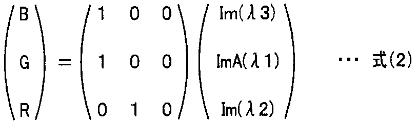
式(2)によれば、深部の血管61は、やや青色あるいは青緑色で示されると共に、表層の毛細血管も赤色~茶色で表示されるので、術者に分かり易い。
さらになお、色変換処理101bでは、上記の式(1)に代えて、次の式(3)を用いてもよい。
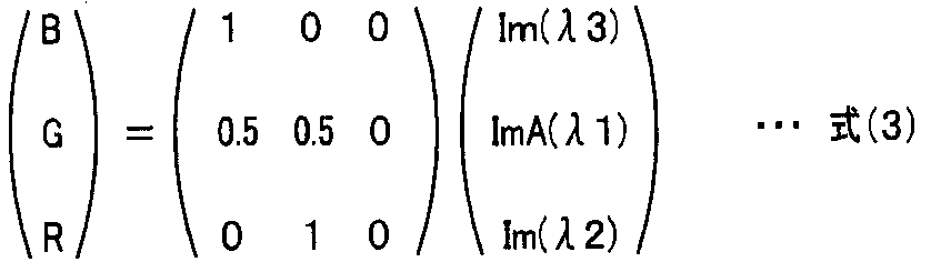
さらになお、色変換処理101bでは、上記の式(1)に代えて、次の式(4)を用いてもよい。ここでαは略1.0~1.5、βは略2.0~2.6、γは略2.5~3.3の数値(例えば、α:β:γ=0.56:1.00:1.17)をとる。この場合、深部血管の色調は青緑色、粘膜の色調は通常観察と類似するため術者がストレスなく観察しやすい。また、αは略2.3~2.7、βは略2.3~2.7、γは略1.7~2.1の数値(例えば、α:β:γ=1.00:1.00:0.76)とすることで、表層および深部の血管の観察が容易となる。
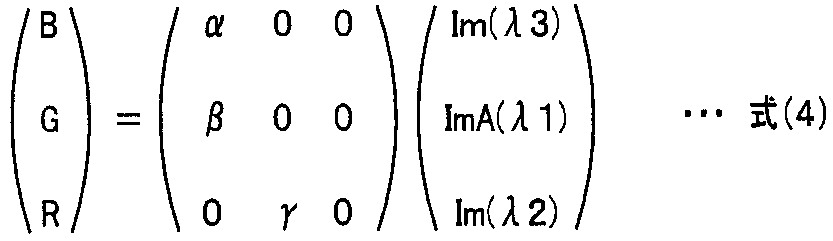
なお、色変換処理部101bにおけるチャンネル割当ての他の例について説明する。例えば、治療時には、上記式(1)に代えて、波長540nm付近の狭帯域光をBチャンネルに、波長630nm付近の狭帯域光をGチャンネルに、波長600nm付近の狭帯域光(すなわち強調補正画像信号BEP1(λ1))をRチャンネルに割り当てるようにしてもよい。
また、診断時には、波長540nm付近の狭帯域光をBチャンネルとGチャンネルに、波長600nm付近の狭帯域光もしくは波長630nm付近の狭帯域光をRチャンネルに割り当てるようにしてもよい。
ここで、色バランス調整について説明する。
例えば、式(1)のように、波長540nm付近の狭帯域光をBチャンネルに、波長600nm付近の狭帯域光をGチャンネルに、波長630nm付近の狭帯域光をRチャンネルに割り当てる場合、Rチャンネルの信号に対して、Bチャンネルの信号を増幅することが望ましい。波長600nm付近の狭帯域光の信号強度は、補正しないで、Bチャンネルに割り当てられる波長540nm付近の狭帯域光の信号強度が、Rチャンネルに割り当てる波長630nm付近の狭帯域光の信号強度の0.7~2.5倍になるように、2つの信号が調整される。なお、色バランス調整を行った後に色変換処理を行ってもよいし、色変換処理後に色バランス処理を行ってもよい。
例えば、式(1)のように、波長540nm付近の狭帯域光をBチャンネルに、波長600nm付近の狭帯域光をGチャンネルに、波長630nm付近の狭帯域光をRチャンネルに割り当てる場合、Rチャンネルの信号に対して、Bチャンネルの信号を増幅することが望ましい。波長600nm付近の狭帯域光の信号強度は、補正しないで、Bチャンネルに割り当てられる波長540nm付近の狭帯域光の信号強度が、Rチャンネルに割り当てる波長630nm付近の狭帯域光の信号強度の0.7~2.5倍になるように、2つの信号が調整される。なお、色バランス調整を行った後に色変換処理を行ってもよいし、色変換処理後に色バランス処理を行ってもよい。
これにより、粘膜、白色調の繊維組織、黄色の出血、黒色の炭化領域、及び、色調が赤色からマゼンダ色の太い血管の間における色調の差がより顕著になり、術者にとって処置あるいは診断が、よりし易い表示画像を得ることができる。
このような色バランス調整のための色バランス調整回路は、図1のW.B25の前段に設けてもよい。その場合、波長540nm付近の狭帯域光と波長630nm付近の狭帯域光の照明光の強度が略等しいときは、色バランス調整回路は、Bチャンネルに割り当てられる波長540nm付近の狭帯域光の信号を、0.7~1.5倍程度し、Rチャンネルに割り当てる波長630nm付近の狭帯域光の信号を、0.6~1.0倍程度にする。
なお、色バランス調整は、色変換処理部101bにおいて行うようにしてもよいし、あるいは光源装置4において照明光の強度を調整して行うようにしてもよいし、撮像素子のカラーフィルタの各色の透過度を調整して行うようにしてもよい。
なお、色バランス調整は、色変換処理部101bにおいて行うようにしてもよいし、あるいは光源装置4において照明光の強度を調整して行うようにしてもよいし、撮像素子のカラーフィルタの各色の透過度を調整して行うようにしてもよい。
(画像処理部における全体の処理の流れ)
次に、画像処理部101における撮像素子2から得られた画像に対する処理の流れを説明する。図7は、画像処理部101における撮像素子2から得られた画像に対する処理の流れを説明するための図である。
図7に示すように、撮像素子2からの3つの画像は、第1から第3の画像信号P1,P2,P3として、画像処理部101に入力される。入力された3つの画像のうち、画像信号P1に対して、帯域分解処理部104による帯域分解処理が行われる。帯域分解処理部104は、画像信号P1を、予め決められた複数の空間周波数に、ここでは空間周波数fr1からfrNのN個の帯域に分解して、N個の帯域画像信号P1(1)、P1(2)、・・・P1(N)を生成する。
N個の帯域画像信号の中から、空間周波数が最も低い画像である帯域画像信号P1(1)に対して、所定のゲイン係数を乗算する等して、強調処理が強調処理部101aで行われる。すなわち、空間周波数が最も低い画像である帯域画像信号P1(1)のみが強調されるように、輝度が調整される。よって、比較的太い血管の画像だけが含まれる帯域画像信号P1(1)だけが強調される。
色変換処理部101bは、第2の画像信号P2と第3の画像信号P3と、強調処理されて得られた強調補正画像信号BEP1(λ1)とに対して、上述したようなチャンネル割り当てによる色変換処理を施して、観察モニタ5へ出力する。
以上のように、図5に示したような生体組織の吸収特性の極大値から極小値の間における上述したような吸収特性を有する狭帯域光を、生体粘膜に照射して、その得られた戻り光の画像に対して、複数の帯域画像信号に帯域分解する帯域分解処理が施される。そして、その得られた複数の帯域画像信号の中で空間周波数が低い少なくとも一つの帯域画像信号に対して強調処理を行うことにより、生体粘膜の比較的深部にある、比較的太い血管が強調され、観察モニタ5の画面上に表示される。よって、術者は、比較的太い血管も見ながら確認して、ESD等の所望の処置を行うことができる。
なお、上述した例では、波長600nm付近の第1の画像信号P1に対して、空間周波数分割処理による帯域分解処理を行い、その中の空間周波数が最も低い帯域画像信号に対して強調処理を行っているが、生体組織の場所や処置部の状態(例えば生体組織の表面が血液で覆われているような場所あるいは状態)によっては、波長630nm付近の第2の画像信号P2に対して、空間周波数分割処理を行って、その中の空間周波数が最も低い帯域画像信号に対して強調処理を行うようにしてもよい。
その場合、波長540nm付近の狭帯域光をBチャンネルに、波長600nm付近の狭帯域光をGチャンネルに、波長630nm付近の狭帯域光(すなわち強調補正画像信号BEP2(λ2))をRチャンネルに割り当てると、太い血管は青~青緑色で表示される。
さらになお、上述した例では、一つの画像信号に対して帯域分解処理を行っているが、例えば波長600nm付近の第1の画像信号P1と波長630nm付近の第2の画像信号P2の両方に対して帯域分解処理を行って、2つの帯域分解処理のそれぞれの中から空間周波数の低い(例えば空間周波数が最も低い)帯域画像を選択して、両者を強調処理して、強調補正画像信号とするようにしてもよい。
この場合、波長540nm付近の狭帯域光をBチャンネルに、波長600nm付近の狭帯域光(すなわち強調補正画像信号BEP1(λ1))をGチャンネルに、波長630nm付近の狭帯域光をRチャンネルに割り当てると、太い血管は青っぽい色で表示される。
また、上述した例では、空間周波数が最も低い帯域画像信号に対して強調処理が行われるが、最も低い帯域画像信号でなく、2番目あるいは3番目に空間周波数が低い帯域画像信号に対して強調処理を行うようにしてもよい。
さらにまた、上述した内視鏡装置1では、第3の狭帯域光NL3を用いて、生体粘膜の表層部に近い部分にある血管も表示可能となっている。
例えば、波長540nm付近の第3の狭帯域光NL3を用いているので、表層部の毛細血管の状態も、太い血管と同時に、観察モニタ5の画面上に表示される。よって、術者は、観察モニタ5の画面上の内視鏡画像を、処置だけでなく、毛細血管の状態、例えば、毛細血管の集中度あるいは分散度の程度から、生体組織の診断、例えば癌の存在診断や癌の範囲を特定するための範囲診断、また、患部の良悪性を判断する鑑別診断にも利用することができる。さらに、より深部の血管を意識した深達度診断等を行うこともできる。
例えば、波長540nm付近の第3の狭帯域光NL3を用いているので、表層部の毛細血管の状態も、太い血管と同時に、観察モニタ5の画面上に表示される。よって、術者は、観察モニタ5の画面上の内視鏡画像を、処置だけでなく、毛細血管の状態、例えば、毛細血管の集中度あるいは分散度の程度から、生体組織の診断、例えば癌の存在診断や癌の範囲を特定するための範囲診断、また、患部の良悪性を判断する鑑別診断にも利用することができる。さらに、より深部の血管を意識した深達度診断等を行うこともできる。
なお、上述した光源装置4は、キセノンランプ11と回転フィルタ14等を用いて、所望の波長帯域の照明光を生成するが、内視鏡装置1においては、点線で示すように、光源装置4は、所望の波長、例えば、第1のフィルタ群に対応するRGBの各波長と、第2のフィルタ群に対応する600nm付近と630nm付近の各波長を出射する複数の発光ダイオード(LED)からなる発光ダイオード群11aを有する発光部11Aを含むように構成してもよい。その場合、発光部11A及びライトガイド15が、被写体に照明光を照射する照射部を構成する。
例えば、図1において、キセノンランプ11、熱線カットフィルタ12、絞り装置13,回転フィルタ14等の代わりに、光源装置4に、点線で示す発光部11Aを設ける。さらに、光源装置4には、発光部11Aの各発光ダイオードを、各モードに応じて、所定のタイミングで駆動するための駆動回路11bが設けられる。複数のLED11aを有する発光部11Aが、電源10から電源を受け、制御回路17からの制御信号の下で、駆動回路11bにより制御されて駆動される。
このような光源装置を用いても、上述した内視鏡装置1を構成しても、上述した効果と同様の効果を得ることができる。
なお、発光部11Aは、所定の複数の狭帯域光を出射するレーザダイオード(LD)を用いてもよい。
このような光源装置を用いても、上述した内視鏡装置1を構成しても、上述した効果と同様の効果を得ることができる。
なお、発光部11Aは、所定の複数の狭帯域光を出射するレーザダイオード(LD)を用いてもよい。
また、光源装置に熱光源、LED、LDの何れを搭載した場合においても、CCD2はモノクロ撮像素子だけでなく、波長帯域制限手段あるいは波長帯域制限部としての、RGBカラーフィルタ、もしくは、補色系のカラーフィルタを設けても上述した効果と同等の効果を得ることができる。
また、図5に示す第2の狭帯域光NL2はヘモグロビンの吸収特性の極小値ACmin(ここでは波長730nmにおける吸収係数)よりも長い波長帯域の光であってもよい。つまり、第2の狭帯域光NL2の波長は、第1の狭帯域光NL1の波長よりも吸収係数が低く、かつ生体組織の散乱特性が抑制された波長帯域である、例えば、740nm, 770nm, 805nm, 810nm, 850nm, 870nm, 880nm, 910nm, 940nm, 1020nm, 1300nmを用いても上述した効果と同等の効果を得ることができる(例えば、狭帯域光NL2を740nm~1300nmのいずれかの波長に設定する場合、狭帯域光NL1は576nm以上で、かつ、少なくとも630nm以下の何れかの波長を設定する)。なお、第2の狭帯域光NL2は、光源装置としてキセノン光源、LED、LDの何れを搭載した場合でも生成することができる。
以上のように、上述した本実施の形態によれば、薬剤投与という煩雑な作業をすることなく、かつ粘膜深部の血管を明瞭に表示可能な内視鏡装置を提供することができる。
(第2の実施の形態)
第1の実施の形態では、少なくとも1つの狭帯域光を照明光として生体組織に実際に照射して、その戻り光の画像に対して上述した帯域分解処理を行い、帯域分解処理により得られた少なくとも1つの帯域画像信号に強調処理が行われているが、本実施の形態では、生体組織に少なくとも1つの狭帯域光を実際に照射しないで、いわゆる分光推定により各狭帯域光の戻り光の画像情報を得て、その分光推定により得られた分光画像信号に対して上述したような帯域分解処理を行い、帯域分解処理により得られた少なくとも1つの帯域画像信号に強調処理が行われる。すなわち、上述した第1の実施の形態では、少なくとも1つの狭帯域光は、回転フィルタあるいは発光ダイオードなどの発光素子を有する照明装置により生成されて、それらの戻り光の画像に対して帯域分解処理が行われるが、本実施の形態では、3つの狭帯域光に対応する画像信号を、分光推定処理により得て、その分光推定により得られた分光推定画像信号に対して帯域分解処理が行われる。
第1の実施の形態では、少なくとも1つの狭帯域光を照明光として生体組織に実際に照射して、その戻り光の画像に対して上述した帯域分解処理を行い、帯域分解処理により得られた少なくとも1つの帯域画像信号に強調処理が行われているが、本実施の形態では、生体組織に少なくとも1つの狭帯域光を実際に照射しないで、いわゆる分光推定により各狭帯域光の戻り光の画像情報を得て、その分光推定により得られた分光画像信号に対して上述したような帯域分解処理を行い、帯域分解処理により得られた少なくとも1つの帯域画像信号に強調処理が行われる。すなわち、上述した第1の実施の形態では、少なくとも1つの狭帯域光は、回転フィルタあるいは発光ダイオードなどの発光素子を有する照明装置により生成されて、それらの戻り光の画像に対して帯域分解処理が行われるが、本実施の形態では、3つの狭帯域光に対応する画像信号を、分光推定処理により得て、その分光推定により得られた分光推定画像信号に対して帯域分解処理が行われる。
図8は、第2の実施の形態に関わる内視鏡装置1Aの構成を示す構成図である。図8において、図1と同じ構成要素については、同一符号を付して説明は省略する。
図8に示すように、光源装置4Aは、白色光を出射するランプ11Bと、熱線カットフィルタ12及び絞り装置13を含んで構成される。光源装置4Aからの照明光は、ライトガイド15を介して、被写体へ照射される。なお、ランプ11Bは、白色光以外の光を出射するものでもよい。
図8に示すように、光源装置4Aは、白色光を出射するランプ11Bと、熱線カットフィルタ12及び絞り装置13を含んで構成される。光源装置4Aからの照明光は、ライトガイド15を介して、被写体へ照射される。なお、ランプ11Bは、白色光以外の光を出射するものでもよい。
内視鏡3の挿入部の先端に設けられた撮像素子2Aは、カラー撮像素子である。撮像素子2Aは、例えばカラーCCDであり、撮像面上に、RGBのカラーフィルタを有する。被写体からの戻り光は、波長帯域制限手段あるいは波長帯域制限部である、RGBのカラーフィルタを介して撮像面の各画素部により受光され、RGBの3色の画像信号が、撮像素子2Aから出力される。
セレクタ100Aは、RGBの3つの画像信号を、画像処理部101Aに出力する。画像処理部101Aは、分光推定部を有し、狭帯域光観察モードのときは、波長600nm付近の分光推定画像信号、波長630nm付近の分光推定画像信号及び波長540nm付近の分光推定画像信号を生成する。
セレクタ100Aは、RGBの3つの画像信号を、画像処理部101Aに出力する。画像処理部101Aは、分光推定部を有し、狭帯域光観察モードのときは、波長600nm付近の分光推定画像信号、波長630nm付近の分光推定画像信号及び波長540nm付近の分光推定画像信号を生成する。
図9は、本実施の形態に関わる狭帯域光観察における全体の処理の流れを説明するための図である。図9において、図3と同じ構成要素は、同一符号を付して説明は省略する。画像処理部101Aは、強調処理部101aと色変換処理部101bと帯域分解処理部104に加えて、分光推定部101cを含む。分光推定部101cは、RGBの3つの画像から、波長600nm付近の第1の分光推定画像信号e1と、波長630nm付近の第2の分光推定画像信号e2と、波長540nm付近の第3の分光推定画像信号e3を、分光推定処理により抽出して帯域分解処理部104へ出力する。
具体的には、分光推定部101cは、3入力から、予め与えられている先験情報に基づいてn次元の分光画像をマトリックス演算により算出して、算出されたn次元の分光推定画像信号の中から選択的にe1,e2,e3を出力する。分光推定部101cは、マトリックス演算等を用いて、波長600nm付近の分光推定画像信号e1と波長630nm付近の分光推定画像信号e2と波長540nm付近の分光推定画像信号e3を算出して出力するように構成されている。
分光推定部101cから出力された第1、第2及び第3の分光推定画像信号は、帯域分解処理部104において帯域分解される。分光推定部101cの後段における、帯域分解処理部104、強調処理部101a及び色変換処理部101bの処理は、上述した第1の実施の形態で説明した処理と同じである。
図10は、3つの広帯域光の画像信号B,G,Rから3つの狭帯域光の分光画像信号e1,e2,e3を推定する場合を説明するための分光特性を示す図である。図10における3つの広帯域光B,G,Rは撮像素子2Aのカラーフィルタにより得られ、その3つの広帯域光B,G,Rの画像信号が分光推定部101cに入力される。
分光推定部101cは、分光推定処理により、3つの広帯域光の画像信号B,G,Rから3つの狭帯域光の分光推定画像信号e1,e2,e3を推定する。図10に示すような波長帯域を有する広帯域光の画像信号B,G,Rから、波長600nm付近の狭帯域光の分光推定画像信号e1、波長630nm付近の狭帯域光の分光推定画像信号e2及び波長540nm付近の狭帯域光の分光推定画像信号e3が分光推定処理により得られる。ここでは、図5における極大値ACmaxと極小値ACminの波長帯域R間の2つの狭帯域光の分光推定画像信号e1,e2と、その波長帯域R外の狭帯域光の分光推定画像信号e3とが分光推定により得られ、分光推定画像信号e1,e2,e3は、帯域分解処理部104に供給される。
なお、3つの広帯域光のうちの2つの広帯域光の画像信号、例えば広帯域光G,Rの画像信号から、3つの分光画像信号e1,e2,e3を分光推定処理により、得るようにしてもよい。
なお、3つの広帯域光のうちの2つの広帯域光の画像信号、例えば広帯域光G,Rの画像信号から、3つの分光画像信号e1,e2,e3を分光推定処理により、得るようにしてもよい。
さらになお、3つ(あるいは2つ)の広帯域光の画像信号は、カラー撮像素子のカラーフィルタを用いて得るのではなく、光源装置において、図10に示したような分光特性の画像信号が得られる感度特性を有する回転フィルタの第1群のフィルタを光路上に配置して生成した3つ(あるいは2つ)の照明光の戻り光をモノクロの撮像素子に当てて、得るようにしてよい。
以上のように、分光推定部101cは、被検体からの戻り光の少なくとも2つの撮像信号に基づき、分光推定処理によって、3つの分光推定画像信号e1,e2,e3を生成して出力する。さらに、分光推定部101cは、その少なくとも2つの撮像信号に基づき、被検体の表層部から所定の距離だけ透過可能な照明光の照射に基づく戻り光に対応する分光推定画像信号e3も分光推定処理によって生成して出力する。そして、上述したように、帯域分解処理部104、強調処理部101a及び色変換処理部101bにおける処理は、第1の実施の形態と同様である。
よって、本実施の形態の内視鏡装置1Aによっても、上述した内視鏡装置1と効果と同様の効果を得ることができる。
よって、本実施の形態の内視鏡装置1Aによっても、上述した内視鏡装置1と効果と同様の効果を得ることができる。
次に、分光推定についての変形例について説明する。
上述した分光推定の処理では、複数の広帯域光の画像信号から複数の狭帯域光の分光画像信号が推定されているが、このような方法に限らず、次のような方法でもよい。
上述した分光推定の処理では、複数の広帯域光の画像信号から複数の狭帯域光の分光画像信号が推定されているが、このような方法に限らず、次のような方法でもよい。
第1の方法は、2つの広帯域光の画像信号と1つの狭帯域光の画像信号から、3つの分光画像信号を推定するものである。狭帯域光の画像信号を用いるので、分光推定の精度を高くすることができる。
図11は、2つの広帯域光の画像信号と1つの狭帯域光の画像信号から、3つの狭帯域光の分光画像信号を推定する場合を説明するための分光特性を示す図である。図11に示すように、B,Gについては広帯域光であり、Rについて狭帯域光が用いられる。分光推定部101cでは、2つの広帯域光の画像信号B,Gと1つの狭帯域光の画像信号Rnから、3つの分光推定画像信号e1,e2,e3が推定される。
2つの広帯域光B,Gと1つの狭帯域光Rnの3つの画像信号は、図11に示すような分光特性を有する撮像素子2Aのカラーフィルタにより得られるようにしてもよいし、あるいは、光源装置において図2に示したような回転フィルタを用いて生成して、3つの照明光(すなわち2つの広帯域光B,Gと1つの狭帯域光Rnの照明光)の戻り光をモノクロの撮像素子に当てて、得るようにしてよい。
2つの広帯域光B,Gと1つの狭帯域光Rnの3つの画像信号は、図11に示すような分光特性を有する撮像素子2Aのカラーフィルタにより得られるようにしてもよいし、あるいは、光源装置において図2に示したような回転フィルタを用いて生成して、3つの照明光(すなわち2つの広帯域光B,Gと1つの狭帯域光Rnの照明光)の戻り光をモノクロの撮像素子に当てて、得るようにしてよい。
なお、図11においても、撮像素子2Aのカラーフィルタによって、2つの広帯域光と1つの狭帯域光の3つの画像信号を得るようにしてもよいし、光源装置が2つ以上の照明光を照射することによって、2つ以上の照明光のうち少なくとも1つの照明光(Rn)の波長帯域が他の照明光(B,G)の波長帯域よりも狭くなるようにしてもよい。
分光推定部101cは、分光推定処理により、2つの広帯域光B,Gの画像信号と1つの狭帯域光の画像信号Rnから3つの狭帯域光の分光推定画像信号e1,e2,e3を推定する。図11に示すような波長帯域を有する2つの広帯域光B,Gの画像信号と1つの狭帯域光の画像信号Rnから、波長600nm付近の狭帯域光の分光推定画像信号e1、波長630nm付近の狭帯域光の分光推定画像信号e2及び波長540nm付近の狭帯域光の分光画像信号e3が推定される。
なお、1つの広帯域光の画像信号(例えば広帯域光Gの画像信号)と1つの狭帯域光Rnの画像信号から、3つの分光推定画像信号e1,e2,e3を分光推定処理により、得るようにしてもよい。
また、図11では、1つの狭帯域光Rnは、波長600nm付近の狭帯域光を含むが、波長630nm付近の狭帯域光を含むものであってもよい。さらに、1つの狭帯域光Rnは、図11において、一点鎖線で示すような、波長600nm付近の狭帯域光も波長630nm付近の狭帯域光も含まないものであってもよい。
さらに、1つの広帯域光の画像信号と2つの狭帯域光の画像信号から、3つの分光推定画像信号e1,e2,e3を推定するようにしてもよい。
さらに、1つの広帯域光の画像信号と2つの狭帯域光の画像信号から、3つの分光推定画像信号e1,e2,e3を推定するようにしてもよい。
さらにまた、4つ以上の狭帯域光の画像信号から、3つの分光画像信号e1,e2,e3を推定するようにしてもよい。
4以上の狭帯域光の画像信号から、3つの分光推定画像信号を推定した方が、3つの狭帯域光の画像信号から、3つの狭帯域光の画像信号を推定する場合に比べて、分光推定精度は向上する。よって、4以上の狭帯域光の画像信号、例えば狭帯域光Bn,Gn,Rnの画像信号から、3つの分光推定画像信号e1,e21,e31を分光推定処理により、得るようにしてもよい。
4以上の狭帯域光の画像信号から、3つの分光推定画像信号を推定した方が、3つの狭帯域光の画像信号から、3つの狭帯域光の画像信号を推定する場合に比べて、分光推定精度は向上する。よって、4以上の狭帯域光の画像信号、例えば狭帯域光Bn,Gn,Rnの画像信号から、3つの分光推定画像信号e1,e21,e31を分光推定処理により、得るようにしてもよい。
図12は、本実施の形態の画像処理部101Aにおける撮像素子2から得られた画像に対する処理の流れを説明するための図である。
図12に示すように、撮像素子2から、3つの画像、すなわち、第1から第3の画像信号P1,P2,P3が、分光推定部101cに入力される。分光推定部101cは、入力された2つ又は3つの画像信号から、3つの分光推定画像信号e1,e2,e3を推定して生成する。
図12に示すように、撮像素子2から、3つの画像、すなわち、第1から第3の画像信号P1,P2,P3が、分光推定部101cに入力される。分光推定部101cは、入力された2つ又は3つの画像信号から、3つの分光推定画像信号e1,e2,e3を推定して生成する。
分光推定部101cで得られた3つの分光画像信号e1,e2,e3のうち、1つの分光画像信号e1に対して、帯域分解処理が帯域分解処理部104において行われる。帯域分解処理により得られた低い空間周波数の帯域画像信号(図12では帯域画像信号P1(1))に対して、強調処理が強調処理部101aで行われる。
すなわち、分光推定部101cは、被検体からの戻り光の少なくとも2つの撮像信号に基づき、分光推定処理によって、第1の画像信号として、分光推定画像信号e1を生成して出力し、帯域分解処理部104は、分光推定画像信号e1を分解処理する。
色変換処理部101bは、第2の分光推定画像信号e2と、第3の分光推定画像信号e3と、強調処理されて得られた強調補正画像信号BEP1(λ1)とに対して、チャンネル割り当てによる色変換処理を施して、観察モニタ5へ出力する。
なお、2つの狭帯域光として、例えば、波長540nm付近の狭帯域光Gnと波長600nm付近の狭帯域光Rnの照明を照射し、得られた2つの画像信号Gn, Rnの画像信号から、波長630nm付近の狭帯域光の分光推定画像信号e2を分光推定して得る。そして、その分光推定画像信号e2に対して強調処理を施し、波長540nm付近の狭帯域光Gnと波長600nm付近の狭帯域光Rnのリアルな画像信号と、強調処理をした分光推定画像信号e2とを用いて画像表示するようにしてもよい。
さらになお、本第2の実施の形態において、撮像素子の表面に設けられるカラーフィルタについては、RGB系のものを例として説明したが、カラーフィルタは、補色系のカラーフィルタでもよい。
本実施の形態の内視鏡においても、上述した強調処理を行うことにより、生体粘膜の比較的深部にある、比較的太い血管が強調され、観察モニタ5の画面上に表示される。よって、術者は、比較的太い血管も見ながら確認して、ESD等の所望の処置を行うことができる。
また、第3の分光推定画像信号e3を用いて、上述した内視鏡装置1Aは、生体粘膜の表層に近い部分にある血管も表示可能となっているので、毛細血管の状態、例えば、毛細血管の集中度あるいは分散度の程度から、生体組織の診断、例えば癌の存在診断や癌の範囲を特定するための範囲診断、また、患部の良悪性を判断する鑑別診断にも利用することができる。さらに、より深部の血管を意識した深達度診断等を行うこともできる。
なお、第3の分光推定画像信号e3に加えて、さらに分光推定して得られた第4,第5の画像も用いて、色変換処理して、観察モニタ5に表示するようにしてもよい。
なお、第3の分光推定画像信号e3に加えて、さらに分光推定して得られた第4,第5の画像も用いて、色変換処理して、観察モニタ5に表示するようにしてもよい。
また、図10~図11に示す第2の分光推定信号e2の有する波長は図5のヘモグロビンの吸収特性の極小値ACmin(ここでは波長730nmにおける吸収係数)よりも長い波長帯域の光であってもよい。つまり、第2の分光推定信号e2の有する波長は、第1の分光推定信号e1の有する波長よりも吸収係数が低く、かつ生体組織の散乱特性が抑制された波長帯域である、例えば、740nm, 770nm, 805nm, 810nm, 850nm, 870nm, 880nm, 910nm, 940nm, 1020nm, 1300nmを用いても上述した効果と同等の効果を得ることができる(例えば、第2の分光推定信号e2の有する波長を740nm~1300nmのいずれかの波長に設定する場合、第1の分光推定信号e1の有する波長は576nm以上で、かつ、少なくとも630nm以下の何れかの波長を設定する)。
以上のように、上述した本実施の形態によれば、薬剤投与という煩雑な作業をすることなく、かつ粘膜深部の血管を明瞭に表示可能な内視鏡装置を提供することができる。
(第3の実施の形態)
第1の実施の形態では、少なくとも1つの狭帯域光を照明光として生体組織に実際に照射して、その戻り光の画像に対して上述した帯域分解処理を行い、帯域分解処理により得られた少なくとも1つの帯域画像信号に強調処理が行われ、第2の実施の形態では、生体組織に少なくとも1つの狭帯域光を実際に照射しないで、いわゆる分光推定により各狭帯域光の戻り光の画像情報を得て、その分光推定により得られた各波長の分光推定画像信号に対して上述したような帯域分解処理と強調処理が行われるが、本第3の実施の形態では、少なくとも2つの狭帯域光の実際の照明光の戻り光の画像信号(あるいは1つの狭帯域光の実際の照明光の戻り光の画像信号と分光推定により得られた分光推定画像信号)に対して帯域分解処理を行い、帯域分解処理により得られた少なくとも2つの帯域画像信号を用いて分光推定処理行い、その分光推定により得られた分光推定画像信号とに対して強調処理が行われる。
本実施の形態の内視鏡装置1Bの構成は、図1に示した内視鏡装置1の構成と同じであるが、本実施の形態の回転フィルタ14Aの構成は異なっている。図13は、本実施の形態の回転フィルタ14Aの構成を示す図である。図13に示すように、回転フィルタ14Aは、図2に示した3つの所定の狭帯域波長の光を透過させる3つのフィルタ14-600,14-630,14-540からなる第2のフィルタ群を有するだけである。面順次の戻り光は、モノクロの撮像素子2において受光される。
なお、回転フィルタ14Aは、図13において括弧で示すように、通常光観察用の分光特性の面順次光を出力するためのフィルタ組を構成するRGBのフィルタ部を用いてもよい。
図14は、本実施の形態に関わる特殊光観察モードにおける全体の処理の流れを説明するための図である。図14において、図9と同じ構成要素は、同一符号を付して説明は省略する。画像処理部101Bは、帯域分解処理部104、強調処理部101a、色変換処理部101b及び分光推定部101cを含む。帯域分解処理部104は、2つの画像信号に対して帯域分解処理を行うので、2つの帯域分解処理部104Aと104Bを含む(図15)。分光推定部101cは、少なくとも2つの入力信号に基づき、分光推定処理によって分光推定画像信号を生成する分光推定手段あるいは分光推定部であり、ここでは、帯域分解処理により得られた少なくとも2つ帯域画像信号から、少なくとも1つの分光推定画像信号eを生成し、その分光推定画像信号eに対して強調処理が行われる。
ここでは、具体的には、波長600nm付近の画像信号P1と波長630nm付近の第2の画像信号P2に対して、2つの帯域分解処理部による帯域分解処理が行われる。そして、2つの画像信号P1とP2のそれぞれについて、帯域分解処理により得られた低い空間周波数の帯域画像信号P1(1)とP2(1)を用いて分光推定処理が行われる。分光推定処理により得られた分光推定画像信号e1に対して強調処理部101aにおいて強調処理が行われる。
図15は、本実施の形態に関わる画像処理部101Bにおける撮像素子2から得られた画像に対する処理の流れを説明するための図である。
図15に示すように、撮像素子2から、3つの画像、すなわち、波長600nm付近の第1の画像信号P1、波長630nm付近の第2の画像信号P2及び波長540nm付近の第3の画像信号P3が、画像処理部101Bに入力される。
図15に示すように、撮像素子2から、3つの画像、すなわち、波長600nm付近の第1の画像信号P1、波長630nm付近の第2の画像信号P2及び波長540nm付近の第3の画像信号P3が、画像処理部101Bに入力される。
第1の画像信号P1と第2の画像信号P2は、それぞれ帯域分解処理部104Aと104Bにより帯域分解処理される。帯域分解処理部104Aと104Bは、上述した帯域分解処理部104と同じ構成である。帯域分解処理により、第1の画像信号P1については、N個の帯域画像信号P1(1)、P1(2)、・・・P1(N)が生成され、第2の画像信号P2についても、N個の帯域画像信号P2(1)、P2(2)、・・・P2(N)が生成される。
ここでは、帯域分解処理部104Aと104Bは、共に同じ数の帯域画像信号を生成しているが、互いに異なる数の帯域画像信号を生成するようにしてもよい。
ここでは、帯域分解処理部104Aと104Bは、共に同じ数の帯域画像信号を生成しているが、互いに異なる数の帯域画像信号を生成するようにしてもよい。
上述したように、空間周波数は、fr1が最も低く、fr2からfrNの順に、高くなっている。よって、N個の帯域画像信号P1(1)、P1(2)、・・・P1(N)のうち、帯域画像信号P1(1)が最も空間周波数の低い画像信号であり、N個の帯域画像信号P2(1)、P2(2)、・・・P2(N)のうち、帯域画像信号P2(1)が最も空間周波数の低い画像信号である(例えば、P1(1)付近およびP2(1)付近の帯域画像信号は、より太い深部の血管などの生体構造物に関する情報を有している。一方、P1(N)付近およびP2(N)付近の帯域画像信号は、より細い粘膜表層の血管や腺構造などの表面凹凸構造に関する情報を有している)。
分光推定部101cは、帯域分解処理部104Aと104Bのそれぞれで生成された複数の帯域画像信号の中の空間周波数の低い帯域画像信号(ここでは最も低い空間周波数の帯域画像信号P1(1)とP2(1))に基づいて、波長600nm付近の第1の画像信号P1の分光推定画像信号e1を推定して生成する。
その分光推定画像信号e1に対して、ゲイン係数を乗算する等による強調処理が強調処理部101aで行われ、強調補正画像信号BEP1(λ1)が色変換処理部101bに出力される。色変換処理部101bは、波長630nm付近の第2の画像信号P2と、波長540nm付近の第3の画像信号P3と、強調処理されて得られた強調補正画像信号BEP1(λ1)に対して、チャンネル割り当てによる色変換処理を施して、観察モニタ5へ出力する。強調処理部101aと色変換処理部101bにおける処理は、第1の実施の形態と同様である。
以上のように、帯域分解処理部104A,Bは、撮像素子2による撮像後、生体組織の吸収特性において極大値ACmaxを含む波長帯域から極小値ACminにおける波長帯域の間で、分光特性のピーク波長を有する第2の画像信号P2に対しても、複数の空間周波数帯域に分解処理を行う。分光推定部101cは、第1の画像信号P1及び第2の画像信号P2のそれぞれについて帯域分解処理部104A,Bにより生成された複数の帯域画像信号の中で、空間周波数が低い帯域画像信号を、少なくとも2つの入力信号として、分光推定処理を行う。そして、強調処理部101aは、分光推定部101cの分光推定処理により得られた分光推定画像信号e1を、所定の第1の帯域画像信号として強調処理を行う。
なお、上記の例では、3つの狭帯域光を照明光として利用しているが、3つのうち全てあるいは一部は広帯域光でもよい。
さらになお、上記の例では、2つの狭帯域光の実際の照明光の戻り光の画像信号である、波長600nm付近の画像信号P1と波長630nm付近の第2の画像信号に対して、帯域分解処理を行っているが、2つの画像信号の少なくとも一方は、分光推定により生成して得られた分光推定画像信号でもよい。
さらになお、上記の例では、2つの狭帯域光の実際の照明光の戻り光の画像信号である、波長600nm付近の画像信号P1と波長630nm付近の第2の画像信号に対して、帯域分解処理を行っているが、2つの画像信号の少なくとも一方は、分光推定により生成して得られた分光推定画像信号でもよい。
例えば、複数の帯域画像信号P1(1)~P1(N)を得るために、第1の画像信号P1に代えて、第2の画像信号P2と第3の画像信号P3から分光推定して得られた分光推定画像信号e1を、帯域分解処理するようにしてもよい。
逆に、複数の帯域画像信号P2(1)~P2(N)を得るために、第2の画像信号P2に代えて、第1の画像信号P1と第3の画像信号P3から分光推定して得られた分光推定画像信号e2を、帯域分解処理するようにしてもよい。
逆に、複数の帯域画像信号P2(1)~P2(N)を得るために、第2の画像信号P2に代えて、第1の画像信号P1と第3の画像信号P3から分光推定して得られた分光推定画像信号e2を、帯域分解処理するようにしてもよい。
以上のように、本実施の形態の内視鏡装置によれば、帯域分解処理により得られた複数の帯域画像信号の中から低い空間周波数の2つの帯域画像を用いて分光推定して、比較的太い血管の分光推定画像を得て、その分光推定画像に対して、強調処理が行われる。
なお、図15における3つの狭帯域光(あるいは広帯域光)は撮像素子2Aのカラーフィルタにより得るようにしてもよい。すなわち、第2の実施の形態で説明したような光源装置4Aと、撮像素子2Aのカラーフィルタを用いて、3つの狭帯域光(あるいは広帯域光)を得るようにしてもよい。
よって、本実施の形態の内視鏡装置1Bによっても、上述した内視鏡装置1及び1Aと効果と同様の効果を得ることができる。
なお、本第3の実施の形態において、撮像素子の表面に設けられるカラーフィルタを用いる場合、RGB系のものを例として説明したが、カラーフィルタは、補色系のカラーフィルタでもよい。
なお、図15における3つの狭帯域光(あるいは広帯域光)は撮像素子2Aのカラーフィルタにより得るようにしてもよい。すなわち、第2の実施の形態で説明したような光源装置4Aと、撮像素子2Aのカラーフィルタを用いて、3つの狭帯域光(あるいは広帯域光)を得るようにしてもよい。
よって、本実施の形態の内視鏡装置1Bによっても、上述した内視鏡装置1及び1Aと効果と同様の効果を得ることができる。
なお、本第3の実施の形態において、撮像素子の表面に設けられるカラーフィルタを用いる場合、RGB系のものを例として説明したが、カラーフィルタは、補色系のカラーフィルタでもよい。
また、図15に示す第2の画像信号P2が有する波長λ2は図5のヘモグロビンの吸収特性の極小値ACmin(ここでは波長730nmにおける吸収係数)よりも長い波長帯域の光であってもよい。つまり、第2の画像信号P2が有する波長は、第1の画像信号P1が有する波長よりも吸収係数が低く、かつ生体組織の散乱特性が抑制された波長帯域である、例えば、740nm, 770nm, 805nm, 810nm, 850nm, 870nm, 880nm, 910nm, 940nm, 1020nm, 1300nmを用いても上述した効果と同等の効果を得ることができる(例えば、第2の画像信号P2の有する波長を740nm~1300nmのいずれかの波長に設定する場合、第1の画像信号P1の有する波長は576nm以上で、かつ、少なくとも630nm以下の何れかの波長を設定する)。
本実施の形態の内視鏡においても、上述した強調処理を行うことにより、生体粘膜の比較的深部にある、比較的太い血管が強調され、観察モニタ5の画面上に表示される。よって、術者は、比較的太い血管も見ながら確認して、ESD等の所望の処置を行うことができる。
また、波長540nm付近の第3の画像信号P3を用いて、上述した内視鏡装置1Aは、生体粘膜の表層に近い部分にある血管も表示可能となっているので、毛細血管の状態、例えば、毛細血管の集中度あるいは分散度の程度から、生体組織の診断、例えば癌の存在診断や癌の範囲を特定するための範囲診断、また、患部の良悪性を判断する鑑別診断にも利用することができる。さらに、より深部の血管を意識した深達度診断等を行うこともできる。
以上のように、上述した本実施の形態によれば、薬剤投与という煩雑な作業をすることなく、かつ粘膜深部の血管を明瞭に表示可能な内視鏡装置を提供することができる。
(各実施の形態について共通の変形例)
(変形例1)
上述した3つの実施の形態及びそれぞれの各変形例では、静脈血の光吸収特性を例に挙げてその特性に基づいて、2つの狭帯域光が選択されているが、動脈血の光吸収特性あるいは静脈血と動脈血の両方を合わせた血の光吸収特性に基づいて、上述したような、少なくとも2つの狭帯域光を選択するようにしてもよい。
(変形例1)
上述した3つの実施の形態及びそれぞれの各変形例では、静脈血の光吸収特性を例に挙げてその特性に基づいて、2つの狭帯域光が選択されているが、動脈血の光吸収特性あるいは静脈血と動脈血の両方を合わせた血の光吸収特性に基づいて、上述したような、少なくとも2つの狭帯域光を選択するようにしてもよい。
(変形例2)
上述した各実施の形態及び各変形例(各実施の形態の変形例を含む)の内視鏡装置では、第1の狭帯域光NL1と第2の狭帯域光NL2の波長として、それぞれ波長600nm付近の光と波長630nm付近の光を用いているが、第1の狭帯域光NL1と第2の狭帯域光NL2の波長としては、好ましくは、それぞれ波長580~620nmの範囲の波長であって所定の幅の範囲の分布を有する狭帯域光と波長610~730nmの範囲の波長であって所定の幅の範囲の分布を有する狭帯域光であり、さらにより好ましくは、それぞれ波長585~615nmの範囲の波長であって所定の幅の範囲の分布を有する狭帯域光と波長620~640nmの範囲の波長であって所定の幅の範囲の分布を有する狭帯域光である。
上述した各実施の形態及び各変形例(各実施の形態の変形例を含む)の内視鏡装置では、第1の狭帯域光NL1と第2の狭帯域光NL2の波長として、それぞれ波長600nm付近の光と波長630nm付近の光を用いているが、第1の狭帯域光NL1と第2の狭帯域光NL2の波長としては、好ましくは、それぞれ波長580~620nmの範囲の波長であって所定の幅の範囲の分布を有する狭帯域光と波長610~730nmの範囲の波長であって所定の幅の範囲の分布を有する狭帯域光であり、さらにより好ましくは、それぞれ波長585~615nmの範囲の波長であって所定の幅の範囲の分布を有する狭帯域光と波長620~640nmの範囲の波長であって所定の幅の範囲の分布を有する狭帯域光である。
従って、吸収特性の極大値から極小値の間で上述したような吸収特性を有する波長の光であれば、第1の狭帯域光NL1と第2の狭帯域光NL2の波長は、それぞれ波長600nm付近の光と波長630nm付近の光に限定されず、どの波長の光でもよい。例えば、第1の狭帯域光NL1と第2の狭帯域光NL2の波長として、それぞれ、波長610nm付近の光と波長645nm付近の光、あるいは波長630nm付近の光と波長660nm付近の光を用いてもよい。
(変形例3)
上述した各実施の形態及び各変形例(各実施の形態の変形例を含む)の内視鏡装置では、第3の狭帯域光NL3として、生体組織の表層の毛細血管を表示させるために、波長540nm付近の光を用いているが、第3の狭帯域光NL3の波長は、これに限定されない。例えば、第3狭帯域光NL3の波長として、波長540nmよりも短い波長415nm付近の光や波長460nm付近の光を用いてもよい。特に、生体組織の表層の情報を得るためには、波長540nm付近の光よりも短い波長415nm付近の光や波長460nmの光が望ましい。
上述した各実施の形態及び各変形例(各実施の形態の変形例を含む)の内視鏡装置では、第3の狭帯域光NL3として、生体組織の表層の毛細血管を表示させるために、波長540nm付近の光を用いているが、第3の狭帯域光NL3の波長は、これに限定されない。例えば、第3狭帯域光NL3の波長として、波長540nmよりも短い波長415nm付近の光や波長460nm付近の光を用いてもよい。特に、生体組織の表層の情報を得るためには、波長540nm付近の光よりも短い波長415nm付近の光や波長460nmの光が望ましい。
(変形例4)
上述した各実施の形態及び各変形例(各実施の形態の変形例を含む)の光源装置では、熱光源のランプ、LED、LD等が用いられることが述べたが、他の手段を用いてもよい。例えば、光源手段あるいは光源部としては、波長可変レーザを用いてもよいし、LEDあるいはLDで蛍光体を励起して、ブロードバンド光を生成して、その光を用いてもよい。
上述した各実施の形態及び各変形例(各実施の形態の変形例を含む)の光源装置では、熱光源のランプ、LED、LD等が用いられることが述べたが、他の手段を用いてもよい。例えば、光源手段あるいは光源部としては、波長可変レーザを用いてもよいし、LEDあるいはLDで蛍光体を励起して、ブロードバンド光を生成して、その光を用いてもよい。
(変形例5)
上述した各実施の形態及び各変形例(各実施の形態の変形例を含む)の内視鏡装置において、狭帯域光を照射する場合、例えば波長600nm付近の狭帯域光はレーザにより生成し、波長630nm付近の狭帯域光は、LEDにより生成するようにしてもよい。レーザ光を用いると、深さ方向におけるノイズを少なくすることができる。また、波長600nm付近の狭帯域光はLEDにより生成し、波長630nm付近の狭帯域光は、レーザにより生成するようにしてもよい。
上述した各実施の形態及び各変形例(各実施の形態の変形例を含む)の内視鏡装置において、狭帯域光を照射する場合、例えば波長600nm付近の狭帯域光はレーザにより生成し、波長630nm付近の狭帯域光は、LEDにより生成するようにしてもよい。レーザ光を用いると、深さ方向におけるノイズを少なくすることができる。また、波長600nm付近の狭帯域光はLEDにより生成し、波長630nm付近の狭帯域光は、レーザにより生成するようにしてもよい。
(変形例6)
上述した各実施の形態及び各変形例(各実施の形態の変形例を含む)では、1つの強調処理結果が得られているが、さらに2つ以上の強調処理結果が得られるようにしてもよい。
上述した各実施の形態及び各変形例(各実施の形態の変形例を含む)では、1つの強調処理結果が得られているが、さらに2つ以上の強調処理結果が得られるようにしてもよい。
図16は、本変形例6を説明するための、静脈血の光の吸収特性を示す図である。図16では、2つの強調処理結果を得られるように、1つは、波長600nm付近の狭帯域光NL1と波長630nm付近の狭帯域光NL2と波長540nm付近の狭帯域光NL3の3つの狭帯域光の組合せに対して強調処理を行い、もう一つは、波長650nm付近の狭帯域光NL12と波長680nm付近の狭帯域光NL22と波長540nm付近の狭帯域光NL3の3つの狭帯域光の組合せに対して強調処理を行うものである。いずれの組合せを選択するかは、ユーザが選択できるようにして、例えば、モード選択により、ユーザは、いずれの組合せで表示を行うかを選択することができる。
なお、もう一つの組合せとしては、波長615nm付近の狭帯域光と波長645nm付近の狭帯域光と波長540nm付近の狭帯域光NL3の組合せ、波長630nm付近の狭帯域光と波長660nm付近の狭帯域光と波長540nm付近の狭帯域光NL3の組合せ、等の組合せでもよい。
第2の組合せの場合、使用される波長は、第1の組合せに比べて長波長側へシフトしているので、より深部の画像が強調される。よって、術者がより深部の血管を強調させたい場合、生体の粘膜表面に血液、胆汁、尿などが付着しているような場合、第2の組合せを選択することによって、所望の血管を強調表示させることが可能となる。
2つ以上の組合せのための強調処理は、光源装置における回転フィルタの組合せを増やす、あるいは、分光推定処理により推定される分光推定画像信号の数を増やすことによって、行うことができる。
2つ以上の組合せのための強調処理は、光源装置における回転フィルタの組合せを増やす、あるいは、分光推定処理により推定される分光推定画像信号の数を増やすことによって、行うことができる。
狭帯域光の波長の組合せとしては、粘膜表面から比較的浅い血管を強調表示させる場合には、波長580nm付近と波長630nm付近と波長540nm付近の組合せと波長590nm付近と波長630nm付近と波長540nm付近の組合せの2つを有することが好ましい。
また、狭帯域光の波長の組合せとしては、粘膜表面からより深部の血管、あるいは血液等の下の粘膜の下の血管を強調表示指せる場合には、波長600nm付近と波長630nm付近と波長540nm付近の組合せと波長650nm付近と波長680nm付近と波長540nm付近の組合せの2つを有することが好ましい。
上述した例では、2つの組合せであるが、3つ以上の組合せでもよい。3つの場合、例えば、波長600nm付近の狭帯域光と波長630nm付近の狭帯域光と波長540nm付近の第1の組合せと、波長650nm付近の狭帯域光と波長680nm付近の狭帯域光と波長540nm付近の第2の組合せと、波長700nm付近の狭帯域光と波長730nm付近の狭帯域光と波長540nm付近の第3の組合せである。
以上のように、複数の強調処理結果が得られるので、術者は、生体の粘膜表面に付着している血液等の濃度が高い場合には、より長波長側の組合せ(例えば、波長650nm付近と波長680nm付近と波長540nm付近の組合せ)を選択し、さらには、血管が比較的浅い部分に有る場合、生体の粘膜表面に付着している血液等の濃度が低い場合には、より短波長側の組合せ(例えば、波長590nm付近と波長630nm付近と波長540nm付近の組合せ)を選択することによって、所望の血管を強調表示させることが可能となる。
例えば、波長600nm付近の狭帯域光と波長630nm付近の狭帯域光の場合、波長600nm付近の狭帯域光は固定し、他方の狭帯域光は、波長630nm付近から730nm付近まで可変で任意に設定できるようにしてもよい。あるいは、他方の波長730nm付近の狭帯域光は固定し、波長590nm付近から620nm付近の狭帯域光までを可変で任意に設定できるようにしてもよい。なお、600nm付近の狭帯域光は固定し、他方の狭帯域光は、730nm以上の波長帯域で任意に設定できるようにしてもよい。
このように、2つの狭帯域光の波長差の一方を固定し、他方を可変にすることによって、所望の領域の血管をより強調して表示させることができる。
このように、2つの狭帯域光の波長差の一方を固定し、他方を可変にすることによって、所望の領域の血管をより強調して表示させることができる。
(変形例7)
また、上述した各実施の形態及び各変形例(各実施の形態の変形例も含む)では、3つの画像を得て、狭帯域画像を観察モニタ5に表示しているが、さらに、4つ目の画像も得るようにして、4つの画像の中から適宜選択して表示画像を生成するようにしてもよい。
また、上述した各実施の形態及び各変形例(各実施の形態の変形例も含む)では、3つの画像を得て、狭帯域画像を観察モニタ5に表示しているが、さらに、4つ目の画像も得るようにして、4つの画像の中から適宜選択して表示画像を生成するようにしてもよい。
内視鏡装置は、通常光観察モードに加えて狭帯域光観察モードを有し、術者は、必要な場面で、通常光観察モードから狭帯域光観察モードへ切り替えて、各種処置を行う。4つ目の画像を加えることにより、各観察モードの表示画像を容易に得ることができる。
例えば、波長540nmよりも波長が短い青色の狭帯域光(あるいは広帯域光でもよい)の照明光もさらに照射可能な光源装置を用い、4つ目の画像を得る。光源装置は、その第4波長の光と波長600nm付近の狭帯域光の第1の組合せの照明光と、波長540nm付近の狭帯域光と波長630nm付近の狭帯域光の第2の組合せの照明光とを交互に、被写体に照射する。なお、第4波長の光と波長540nm付近の狭帯域光と波長600nm付近の狭帯域光の組合せの照明光と、波長630nm付近の狭帯域光の照明光とを交互に、被写体に照射するようにしてもよい。
そして、各照明光の戻り光を、RGBのカラーフィルタを有する撮像素子で受光する。例えば、第4波長の戻り光は、カラーフィルタのB帯域で、波長600nm付近の狭帯域光の戻り光は、R帯域で撮像される。なお、撮像素子のカラーフィルタは、補色系のものであってもよい。さらになお、撮像素子は、モノクロの撮像素子でもよい。
各帯域の画像は分離されるので、ビデオプロセッサ7内では、4つのモノクロ画像が得られる。なお、各画像を得るために、各光の画像信号に対して、適切な色バランス調整は行われる。
そして、ビデオプロセッサ7内では、通常光観察モード用の通常画像は、第4波長の光、波長540nm付近の狭帯域光、波長600nm付近の狭帯域光及び波長630nm付近の狭帯域光の4つの戻り光の画像を用いて、生成される。
また、ビデオプロセッサ7内では、第1の狭帯域光画像を、第4波長の光の画像信号をBとGチャンネルに割り当て、波長540nm付近の狭帯域光の画像信号をRチャンネルに割り当て、第4波長の光と波長540nm付近の狭帯域光の2つの画像を用いて生成する。
さらに、ビデオプロセッサ7内では、第2の狭帯域光画像を、波長540nm付近の狭帯域光、波長600nm付近の狭帯域光及び波長630nm付近の狭帯域光の3つの画像を用いて生成する。
なお、波長600nm付近の狭帯域光の画像信号は、強調処理されている。
なお、波長600nm付近の狭帯域光の画像信号は、強調処理されている。
そして、術者による画像表示指示に応じて、上記のようにして生成された画像が選択されて観察モニタ5に表示される。
このような構成によれば、通常光観察用の通常画像と、狭帯域光観察用の狭帯域光画像の同時表示、あるいは通常画像と狭帯域光画像の重畳表示を行うこともできる。例えば、通常光画像と第1の狭帯域光画像(あるいは第2の狭帯域光画像)の並列表示、あるいは、第1の狭帯域光画像と第2の狭帯域光画像の並列表示を行うことができる。
このような構成によれば、通常光観察用の通常画像と、狭帯域光観察用の狭帯域光画像の同時表示、あるいは通常画像と狭帯域光画像の重畳表示を行うこともできる。例えば、通常光画像と第1の狭帯域光画像(あるいは第2の狭帯域光画像)の並列表示、あるいは、第1の狭帯域光画像と第2の狭帯域光画像の並列表示を行うことができる。
さらに、第4波長の光の画像信号をBチャンネルに、波長540nm付近の狭帯域光の画像信号をGチャンネルに、波長600nm付近の狭帯域光の画像信号をRチャンネルに割り当てることによって、あるいは第4波長の光の画像信号をBチャンネルに、波長540nm付近の狭帯域光の画像信号と波長600nm付近の狭帯域光の画像信号をGチャンネルに、波長600nm付近の狭帯域光の画像信号(あるいは波長600nm付近の狭帯域光の画像信号と波長630nm付近の狭帯域光の画像信号と)をRチャンネルに割り当てることによって、通常画像に深部の血管情報を付加した重畳が画像を生成して観察モニタ5に表示することもできる。
さらにあるいは、第4波長の光の画像信号をBチャンネルに、第4波長の光の画像信号と波長600nm付近の狭帯域光の画像信号をGチャンネルに、波長600nm付近の狭帯域光の画像信号(あるいは波長600nm付近の狭帯域光の画像信号と波長630nm付近の狭帯域光の画像信号と)をRチャンネルに割り当てることによって、表層の血管と深部の血管の両方を強調した画像を生成して観察モニタ5に表示することもできる。
なお、4つ目の波長の画像信号は、分光推定により生成するようにしてもよい。
以上のように、本変形例7によれば、通常画像と狭帯域光画像の並列表示、あるいは重畳表示が可能となる。
以上のように、本変形例7によれば、通常画像と狭帯域光画像の並列表示、あるいは重畳表示が可能となる。
以上のように、上述した各実施の形態及び各変形例(各実施の形態の変形例も含む)によれば、薬剤投与という煩雑な作業をすることなく、かつ粘膜深部の血管を明瞭に表示可能な内視鏡装置を提供することができる。
本発明は、上述した実施の形態に限定されるものではなく、本発明の要旨を変えない範囲において、種々の変更、改変等が可能である。
本出願は、2012年3月30日に日本国に出願された特願2012-82285号を優先権主張の基礎として出願するものであり、上記の開示内容は、本願明細書、請求の範囲に引用されるものとする。
Claims (16)
- 被検体に対し、所定の波長帯域を有する少なくとも1つ以上の照明光を照射する照明部と、
前記照明部の照射に基づく前記被検体からの戻り光を撮像する撮像部と、
前記撮像部による撮像後、生体組織の吸収特性において極大値を含む波長帯域から極小値における波長帯域の間で、分光特性のピーク波長を有する第1の画像信号に対して、複数の空間周波数帯域に分解処理を行う帯域分解処理部と、
前記帯域分解処理部により分解処理されて得られた複数の帯域画像信号のうちの、所定の第1の帯域画像信号に基づいて、強調処理を行い強調補正した画像信号を生成する画像処理部と、
前記強調補正した画像信号を表示する表示部と、
を備えることを特徴とする内視鏡装置。 - 前記所定の第1の帯域画像信号は、前記複数の空間周波数帯域の中で、空間周波数が低い1又は2以上の帯域画像信号であることを特徴とする請求項1に記載の内視鏡装置。
- 前記所定の第1の帯域画像信号は、前記複数の空間周波数帯域の中で、空間周波数が最も低い帯域画像信号であることを特徴とする請求項2に記載の内視鏡装置。
- 前記帯域分解処理部は、前記撮像部による撮像後、前記生体組織の吸収特性において前記極大値を含む波長帯域から前記極小値における波長帯域の間で、分光特性のピーク波長を有する第2の画像信号に対しても、前記複数の空間周波数帯域に分解処理を行い、
前記画像処理部は、前記所定の第1の帯域画像信号に加えて、前記第2の画像信号について分解処理により得られた複数の帯域画像信号のうちの所定の第2の帯域画像信号に基づいて、前記強調処理を行い前記強調補正した画像信号を生成することを特徴とする請求項1に記載の内視鏡装置。 - 前記照明部は、前記生体組織の前記吸収特性において前記極大値を含む波長帯域から前記極小値における波長帯域の間で分光特性のピーク波長を有する第1の照明光と、前記第1の画像信号より前記吸収特性における値が低くかつ前記生体組織の散乱特性が抑制された分光特性のピーク波長を有する第2の照明光と、を照射することを特徴とする請求項1から4のいずれか1つに記載の内視鏡装置。
- 前記照明部は、前記被検体の表層部から所定の距離だけ透過可能な第3の照明光を照射し
前記画像処理部は、前記第1の画像信号、前記第2の画像信号、及び前記第3の照明光の照射に基づき前記撮像部により撮像した第3の画像信号に基づいて、前記強調補正した画像信号を生成することを特徴とする請求項5に記載の内視鏡装置。 - 前記内視鏡装置は、通常光観察モードと狭帯域光観察モードを有し、
前記照明部は、前記狭帯域光観察モードのときに、前記第1の照明光と前記第2の照明光と、を照射することを特徴とする請求項5に記載の内視鏡装置。 - 前記照明部は、光源からの光を透過させるための前記通常光観察モード用のフィルタと前記狭帯域光観察モード用のフィルタを有し、
前記照明部は、前記狭帯域光観察モードのときに、前記光源からの光を前記狭帯域光観察モード用のフィルタを通して出射することによって、前記第1の照明光と前記第2の照明光と、を照射することを特徴とする請求項7に記載の内視鏡装置。 - 前記被検体からの前記戻り光の少なくとも2つの撮像信号に基づき、分光推定処理によって、前記第1の画像信号として、分光推定画像信号を、生成して出力する分光推定部を有し、
前記帯域分解処理部は、前記分光推定画像信号を前記第1の画像信号として前記分解処理を行うことを特徴とする請求項1に記載の内視鏡装置。 - 少なくとも2つの入力信号に基づき、分光推定処理によって分光推定画像信号を生成する分光推定部を有し、
前記帯域分解処理部は、前記撮像部による撮像後、前記生体組織の吸収特性において前記極大値を含む波長帯域から前記極小値における波長帯域の間で、分光特性のピーク波長を有する第2の画像信号に対しても、前記複数の空間周波数帯域に分解処理を行い、
前記分光推定部は、前記第1の画像信号及び前記第2の画像信号のそれぞれについて前記帯域分解処理部により生成された複数の帯域画像信号の中で、空間周波数が低い帯域画像信号を、前記少なくとも2つの入力信号として、前記分光推定処理を行い、
前記画像処理部は、前記分光推定部の前記分光推定処理により得られた前記分光推定画像信号を、前記所定の第1の帯域画像信号として前記強調処理を行うことを特徴とする請求項1に記載の内視鏡装置。 - 前記少なくとも2つの入力信号は、それぞれ、前記第1の画像信号及び前記第2の画像信号について前記帯域分解処理部により生成された複数の帯域画像信号の中で、空間周波数が最も低い帯域画像信号であることを特徴とする請求項10に記載の内視鏡装置。
- 前記第1の画像信号の前記ピーク波長は、波長585から615nmの間にあることを特徴とする請求項1から4のいずれか1つに記載の内視鏡装置。
- 前記第1の画像信号の前記ピーク波長は、波長600nm付近の狭帯域光であることを特徴とする請求項12に記載の内視鏡装置。
- 前記第1の画像信号の前記ピーク波長は、波長600nm付近の狭帯域光であり、前記第2の画像信号の前記ピーク波長は、波長610から730nmの間にあることを特徴とする請求項4に記載の内視鏡装置。
- 前記第2の画像信号の前記ピーク波長は、波長630nm付近の狭帯域光であることを特徴とする請求項14に記載の内視鏡装置。
- 前記第1の画像信号の前記ピーク波長は、波長600nm付近の狭帯域光であり、前記第2の画像信号の前記ピーク波長は、波長730nm以降の狭帯域光であることを特徴とする請求項4に記載の内視鏡装置。
Priority Applications (4)
| Application Number | Priority Date | Filing Date | Title |
|---|---|---|---|
| JP2013525025A JP5355827B1 (ja) | 2012-03-30 | 2012-11-06 | 内視鏡装置 |
| EP12873120.5A EP2687148B1 (en) | 2012-03-30 | 2012-11-06 | Endoscopic device |
| CN201280020001.1A CN103501683B (zh) | 2012-03-30 | 2012-11-06 | 内窥镜装置 |
| US13/910,394 US8723940B2 (en) | 2012-03-30 | 2013-06-05 | Endoscope apparatus |
Applications Claiming Priority (2)
| Application Number | Priority Date | Filing Date | Title |
|---|---|---|---|
| JP2012082285 | 2012-03-30 | ||
| JP2012-082285 | 2012-03-30 |
Related Child Applications (1)
| Application Number | Title | Priority Date | Filing Date |
|---|---|---|---|
| US13/910,394 Continuation US8723940B2 (en) | 2012-03-30 | 2013-06-05 | Endoscope apparatus |
Publications (1)
| Publication Number | Publication Date |
|---|---|
| WO2013145408A1 true WO2013145408A1 (ja) | 2013-10-03 |
Family
ID=49258746
Family Applications (1)
| Application Number | Title | Priority Date | Filing Date |
|---|---|---|---|
| PCT/JP2012/078742 WO2013145408A1 (ja) | 2012-03-30 | 2012-11-06 | 内視鏡装置 |
Country Status (5)
| Country | Link |
|---|---|
| US (1) | US8723940B2 (ja) |
| EP (1) | EP2687148B1 (ja) |
| JP (1) | JP5355827B1 (ja) |
| CN (1) | CN103501683B (ja) |
| WO (1) | WO2013145408A1 (ja) |
Cited By (3)
| Publication number | Priority date | Publication date | Assignee | Title |
|---|---|---|---|---|
| JPWO2016059906A1 (ja) * | 2014-10-16 | 2017-04-27 | オリンパス株式会社 | 内視鏡装置及び内視鏡用光源装置 |
| WO2018198255A1 (ja) * | 2017-04-26 | 2018-11-01 | オリンパス株式会社 | 画像処理装置、画像処理装置の作動方法およびプログラム |
| WO2020188727A1 (ja) * | 2019-03-19 | 2020-09-24 | オリンパス株式会社 | 内視鏡装置、内視鏡装置の作動方法及びプログラム |
Families Citing this family (14)
| Publication number | Priority date | Publication date | Assignee | Title |
|---|---|---|---|---|
| JP5869541B2 (ja) * | 2013-09-13 | 2016-02-24 | 富士フイルム株式会社 | 内視鏡システム及びプロセッサ装置並びに内視鏡システムの作動方法 |
| JP6336098B2 (ja) * | 2015-03-17 | 2018-06-06 | オリンパス株式会社 | 生体観察システム |
| WO2017070274A1 (en) | 2015-10-22 | 2017-04-27 | Covidien Lp | Systems and methods for amplifying changes in a region of interest in a surgical environment |
| WO2017170232A1 (ja) * | 2016-03-30 | 2017-10-05 | 富士フイルム株式会社 | 内視鏡画像信号処理装置および方法並びにプログラム |
| JP6392486B1 (ja) * | 2017-02-01 | 2018-09-19 | オリンパス株式会社 | 内視鏡システム |
| CN110573056B (zh) * | 2017-05-02 | 2021-11-30 | 奥林巴斯株式会社 | 内窥镜系统 |
| JP6876810B2 (ja) * | 2017-08-28 | 2021-05-26 | Hoya株式会社 | 内視鏡用光源装置及び内視鏡システム |
| JP6810812B2 (ja) | 2017-09-13 | 2021-01-06 | オリンパス株式会社 | 内視鏡装置、内視鏡装置の作動方法及びプログラム |
| WO2019171615A1 (ja) * | 2018-03-05 | 2019-09-12 | オリンパス株式会社 | 内視鏡システム |
| WO2019171703A1 (ja) * | 2018-03-05 | 2019-09-12 | オリンパス株式会社 | 内視鏡システム |
| WO2019234829A1 (ja) * | 2018-06-05 | 2019-12-12 | オリンパス株式会社 | 内視鏡システム |
| JPWO2020035929A1 (ja) * | 2018-08-16 | 2021-08-10 | オリンパス株式会社 | 内視鏡装置、内視鏡装置の作動方法及び画像処理プログラム |
| CN111579498B (zh) * | 2020-04-26 | 2021-08-06 | 中国科学院苏州生物医学工程技术研究所 | 基于推扫成像的高光谱内窥成像系统 |
| CN114305300B (zh) * | 2022-02-25 | 2022-06-07 | 杭州莱恩瑟特医疗技术有限公司 | 摆动滤波器、内窥镜用照明装置以及医用内窥镜 |
Citations (7)
| Publication number | Priority date | Publication date | Assignee | Title |
|---|---|---|---|---|
| JPH02104332A (ja) * | 1988-10-14 | 1990-04-17 | Olympus Optical Co Ltd | 分光測定用内視鏡装置 |
| JPH04200433A (ja) * | 1990-11-29 | 1992-07-21 | Olympus Optical Co Ltd | 内視鏡画像処理装置 |
| JP2000041942A (ja) | 1998-07-31 | 2000-02-15 | Olympus Optical Co Ltd | 内視鏡装置 |
| JP2004202217A (ja) * | 2002-12-12 | 2004-07-22 | Olympus Corp | イメージング装置 |
| JP2006141711A (ja) * | 2004-11-19 | 2006-06-08 | Olympus Corp | 内視鏡観察光学系 |
| JP2008023041A (ja) * | 2006-07-20 | 2008-02-07 | Fujifilm Corp | 画像処理方法、および装置、並びに電子内視鏡システム |
| JP2011193983A (ja) * | 2010-03-18 | 2011-10-06 | Olympus Corp | 内視鏡システム、撮像装置及び制御方法 |
Family Cites Families (7)
| Publication number | Priority date | Publication date | Assignee | Title |
|---|---|---|---|---|
| US5078150A (en) | 1988-05-02 | 1992-01-07 | Olympus Optical Co., Ltd. | Spectral diagnosing apparatus with endoscope |
| JP2001104245A (ja) * | 1999-10-06 | 2001-04-17 | Olympus Optical Co Ltd | 内視鏡及び内視鏡装置 |
| JP3820156B2 (ja) * | 2002-01-16 | 2006-09-13 | オリンパス株式会社 | 内視鏡システム |
| JP4787032B2 (ja) * | 2006-02-06 | 2011-10-05 | Hoya株式会社 | 内視鏡画像信号処理装置および電子内視鏡システム |
| JP4868976B2 (ja) * | 2006-08-18 | 2012-02-01 | オリンパスメディカルシステムズ株式会社 | 内視鏡装置 |
| EP2335560B1 (en) * | 2008-10-17 | 2014-11-26 | Olympus Medical Systems Corp. | Endoscope system and endoscopic image processing apparatus |
| JP5498456B2 (ja) * | 2011-09-20 | 2014-05-21 | 株式会社東芝 | 電子内視鏡装置 |
-
2012
- 2012-11-06 CN CN201280020001.1A patent/CN103501683B/zh active Active
- 2012-11-06 EP EP12873120.5A patent/EP2687148B1/en active Active
- 2012-11-06 JP JP2013525025A patent/JP5355827B1/ja active Active
- 2012-11-06 WO PCT/JP2012/078742 patent/WO2013145408A1/ja active Application Filing
-
2013
- 2013-06-05 US US13/910,394 patent/US8723940B2/en active Active
Patent Citations (7)
| Publication number | Priority date | Publication date | Assignee | Title |
|---|---|---|---|---|
| JPH02104332A (ja) * | 1988-10-14 | 1990-04-17 | Olympus Optical Co Ltd | 分光測定用内視鏡装置 |
| JPH04200433A (ja) * | 1990-11-29 | 1992-07-21 | Olympus Optical Co Ltd | 内視鏡画像処理装置 |
| JP2000041942A (ja) | 1998-07-31 | 2000-02-15 | Olympus Optical Co Ltd | 内視鏡装置 |
| JP2004202217A (ja) * | 2002-12-12 | 2004-07-22 | Olympus Corp | イメージング装置 |
| JP2006141711A (ja) * | 2004-11-19 | 2006-06-08 | Olympus Corp | 内視鏡観察光学系 |
| JP2008023041A (ja) * | 2006-07-20 | 2008-02-07 | Fujifilm Corp | 画像処理方法、および装置、並びに電子内視鏡システム |
| JP2011193983A (ja) * | 2010-03-18 | 2011-10-06 | Olympus Corp | 内視鏡システム、撮像装置及び制御方法 |
Non-Patent Citations (1)
| Title |
|---|
| See also references of EP2687148A4 |
Cited By (7)
| Publication number | Priority date | Publication date | Assignee | Title |
|---|---|---|---|---|
| JPWO2016059906A1 (ja) * | 2014-10-16 | 2017-04-27 | オリンパス株式会社 | 内視鏡装置及び内視鏡用光源装置 |
| WO2018198255A1 (ja) * | 2017-04-26 | 2018-11-01 | オリンパス株式会社 | 画像処理装置、画像処理装置の作動方法およびプログラム |
| US11564560B2 (en) | 2017-04-26 | 2023-01-31 | Olympus Corporation | Image processing apparatus, operating method of image processing apparatus, and computer-readable recording medium |
| WO2020188727A1 (ja) * | 2019-03-19 | 2020-09-24 | オリンパス株式会社 | 内視鏡装置、内視鏡装置の作動方法及びプログラム |
| JPWO2020188727A1 (ja) * | 2019-03-19 | 2020-09-24 | ||
| CN113543689A (zh) * | 2019-03-19 | 2021-10-22 | 奥林巴斯株式会社 | 内窥镜装置、内窥镜装置的工作方法以及程序 |
| JP7158562B2 (ja) | 2019-03-19 | 2022-10-21 | オリンパス株式会社 | 内視鏡装置、内視鏡装置の作動方法及びプログラム |
Also Published As
| Publication number | Publication date |
|---|---|
| CN103501683B (zh) | 2015-10-07 |
| JP5355827B1 (ja) | 2013-11-27 |
| US8723940B2 (en) | 2014-05-13 |
| CN103501683A (zh) | 2014-01-08 |
| US20130329027A1 (en) | 2013-12-12 |
| EP2687148B1 (en) | 2018-05-16 |
| JPWO2013145408A1 (ja) | 2015-12-10 |
| EP2687148A1 (en) | 2014-01-22 |
| EP2687148A4 (en) | 2016-01-20 |
Similar Documents
| Publication | Publication Date | Title |
|---|---|---|
| JP5355827B1 (ja) | 内視鏡装置 | |
| JP5404968B1 (ja) | 内視鏡装置 | |
| JP5427318B1 (ja) | 内視鏡装置 | |
| JP5362149B1 (ja) | 内視鏡装置 | |
| JP5215506B2 (ja) | 内視鏡装置 | |
| JP5496075B2 (ja) | 内視鏡診断装置 | |
| JP5355820B2 (ja) | 画像処理装置及び内視鏡システム | |
| JP5167440B2 (ja) | 内視鏡装置 | |
| JP5159904B2 (ja) | 内視鏡診断装置 | |
| JP5757891B2 (ja) | 電子内視鏡システム、画像処理装置、画像処理装置の作動方法及び画像処理プログラム | |
| WO2017104046A1 (ja) | 内視鏡装置 | |
| JP6342598B1 (ja) | 画像処理装置 |
Legal Events
| Date | Code | Title | Description |
|---|---|---|---|
| ENP | Entry into the national phase |
Ref document number: 2013525025 Country of ref document: JP Kind code of ref document: A |
|
| WWE | Wipo information: entry into national phase |
Ref document number: 2012873120 Country of ref document: EP |
|
| 121 | Ep: the epo has been informed by wipo that ep was designated in this application |
Ref document number: 12873120 Country of ref document: EP Kind code of ref document: A1 |
|
| NENP | Non-entry into the national phase |
Ref country code: DE |