WO2013145384A1 - 作業機械 - Google Patents
作業機械 Download PDFInfo
- Publication number
- WO2013145384A1 WO2013145384A1 PCT/JP2012/075658 JP2012075658W WO2013145384A1 WO 2013145384 A1 WO2013145384 A1 WO 2013145384A1 JP 2012075658 W JP2012075658 W JP 2012075658W WO 2013145384 A1 WO2013145384 A1 WO 2013145384A1
- Authority
- WO
- WIPO (PCT)
- Prior art keywords
- exhaust pipe
- cover
- seat
- disposed
- driver
- Prior art date
- Legal status (The legal status is an assumption and is not a legal conclusion. Google has not performed a legal analysis and makes no representation as to the accuracy of the status listed.)
- Ceased
Links
Images









Classifications
-
- E—FIXED CONSTRUCTIONS
- E02—HYDRAULIC ENGINEERING; FOUNDATIONS; SOIL SHIFTING
- E02F—DREDGING; SOIL-SHIFTING
- E02F3/00—Dredgers; Soil-shifting machines
- E02F3/04—Dredgers; Soil-shifting machines mechanically-driven
- E02F3/28—Dredgers; Soil-shifting machines mechanically-driven with digging tools mounted on a dipper- or bucket-arm, i.e. there is either one arm or a pair of arms, e.g. dippers, buckets
- E02F3/30—Dredgers; Soil-shifting machines mechanically-driven with digging tools mounted on a dipper- or bucket-arm, i.e. there is either one arm or a pair of arms, e.g. dippers, buckets with a dipper-arm pivoted on a cantilever beam, i.e. boom
- E02F3/32—Dredgers; Soil-shifting machines mechanically-driven with digging tools mounted on a dipper- or bucket-arm, i.e. there is either one arm or a pair of arms, e.g. dippers, buckets with a dipper-arm pivoted on a cantilever beam, i.e. boom working downwardly and towards the machine, e.g. with backhoes
- E02F3/325—Backhoes of the miniature type
-
- B—PERFORMING OPERATIONS; TRANSPORTING
- B60—VEHICLES IN GENERAL
- B60K—ARRANGEMENT OR MOUNTING OF PROPULSION UNITS OR OF TRANSMISSIONS IN VEHICLES; ARRANGEMENT OR MOUNTING OF PLURAL DIVERSE PRIME-MOVERS IN VEHICLES; AUXILIARY DRIVES FOR VEHICLES; INSTRUMENTATION OR DASHBOARDS FOR VEHICLES; ARRANGEMENTS IN CONNECTION WITH COOLING, AIR INTAKE, GAS EXHAUST OR FUEL SUPPLY OF PROPULSION UNITS IN VEHICLES
- B60K13/00—Arrangement in connection with combustion air intake or gas exhaust of propulsion units
- B60K13/04—Arrangement in connection with combustion air intake or gas exhaust of propulsion units concerning exhaust
-
- B—PERFORMING OPERATIONS; TRANSPORTING
- B62—LAND VEHICLES FOR TRAVELLING OTHERWISE THAN ON RAILS
- B62D—MOTOR VEHICLES; TRAILERS
- B62D33/00—Superstructures for load-carrying vehicles
- B62D33/06—Drivers' cabs
- B62D33/0617—Drivers' cabs for tractors or off-the-road vehicles
-
- B—PERFORMING OPERATIONS; TRANSPORTING
- B62—LAND VEHICLES FOR TRAVELLING OTHERWISE THAN ON RAILS
- B62D—MOTOR VEHICLES; TRAILERS
- B62D33/00—Superstructures for load-carrying vehicles
- B62D33/06—Drivers' cabs
- B62D33/063—Drivers' cabs movable from one position into at least one other position, e.g. tiltable, pivotable about a vertical axis, displaceable from one side of the vehicle to the other
- B62D33/0633—Drivers' cabs movable from one position into at least one other position, e.g. tiltable, pivotable about a vertical axis, displaceable from one side of the vehicle to the other pivotable about a vertical axis
-
- E—FIXED CONSTRUCTIONS
- E02—HYDRAULIC ENGINEERING; FOUNDATIONS; SOIL SHIFTING
- E02F—DREDGING; SOIL-SHIFTING
- E02F9/00—Component parts of dredgers or soil-shifting machines, not restricted to one of the kinds covered by groups E02F3/00 - E02F7/00
- E02F9/08—Superstructures; Supports for superstructures
- E02F9/0858—Arrangement of component parts installed on superstructures not otherwise provided for, e.g. electric components, fenders, air-conditioning units
- E02F9/0866—Engine compartment, e.g. heat exchangers, exhaust filters, cooling devices, silencers, mufflers, position of hydraulic pumps in the engine compartment
-
- E—FIXED CONSTRUCTIONS
- E02—HYDRAULIC ENGINEERING; FOUNDATIONS; SOIL SHIFTING
- E02F—DREDGING; SOIL-SHIFTING
- E02F9/00—Component parts of dredgers or soil-shifting machines, not restricted to one of the kinds covered by groups E02F3/00 - E02F7/00
- E02F9/08—Superstructures; Supports for superstructures
- E02F9/0858—Arrangement of component parts installed on superstructures not otherwise provided for, e.g. electric components, fenders, air-conditioning units
- E02F9/0891—Lids or bonnets or doors or details thereof
-
- E—FIXED CONSTRUCTIONS
- E02—HYDRAULIC ENGINEERING; FOUNDATIONS; SOIL SHIFTING
- E02F—DREDGING; SOIL-SHIFTING
- E02F9/00—Component parts of dredgers or soil-shifting machines, not restricted to one of the kinds covered by groups E02F3/00 - E02F7/00
- E02F9/16—Cabins, platforms, or the like, for drivers
- E02F9/163—Structures to protect drivers, e.g. cabins, doors for cabins; Falling object protection structure [FOPS]; Roll over protection structure [ROPS]
-
- B—PERFORMING OPERATIONS; TRANSPORTING
- B60—VEHICLES IN GENERAL
- B60Y—INDEXING SCHEME RELATING TO ASPECTS CROSS-CUTTING VEHICLE TECHNOLOGY
- B60Y2200/00—Type of vehicle
- B60Y2200/40—Special vehicles
- B60Y2200/41—Construction vehicles, e.g. graders, excavators
- B60Y2200/412—Excavators
-
- F—MECHANICAL ENGINEERING; LIGHTING; HEATING; WEAPONS; BLASTING
- F01—MACHINES OR ENGINES IN GENERAL; ENGINE PLANTS IN GENERAL; STEAM ENGINES
- F01N—GAS-FLOW SILENCERS OR EXHAUST APPARATUS FOR MACHINES OR ENGINES IN GENERAL; GAS-FLOW SILENCERS OR EXHAUST APPARATUS FOR INTERNAL-COMBUSTION ENGINES
- F01N2590/00—Exhaust or silencing apparatus adapted to particular use, e.g. for military applications, airplanes, submarines
- F01N2590/08—Exhaust or silencing apparatus adapted to particular use, e.g. for military applications, airplanes, submarines for heavy duty applications, e.g. trucks, buses, tractors, locomotives
Definitions
- the present invention relates to a working machine such as a mini-excavator equipped with an exhaust pipe that discharges engine exhaust gas at a position above the vehicle body.
- Small work machines such as mini-excavators are often used in relatively narrow work places for landscaping and piping work.
- exhaust pipe exhaust port when the exhaust pipe exhaust port is located on the lower side of the vehicle body, exhaust gas is directed toward a relatively low planting structure or low height structure present around the working machine. It is likely to be released and adversely affect these plants and structures.
- the present invention has been made from the situation in the above-mentioned prior art, and its object is to provide a working machine capable of securing a good rearward visibility of an operator seated at the driver's seat.
- the present invention provides a rotating body, a working device attached to the rotating body, a driver's seat disposed on the rotating body, a counterweight disposed behind the driver's seat, and
- a working machine provided with a muffler disposed on a revolving structure and having an exhaust port for emitting exhaust gas discharged from the muffler at an upper position of the counterweight, the exhaust pipe introducing the exhaust gas of the engine and the above-mentioned operation
- a virtual straight line connecting the seat reference point of the driver's seat and any one of the plurality of support columns, or a vicinity of the virtual straight line, including a plurality of support columns standing on the rear side of the seat It is characterized in that the exhaust pipe is disposed at a position.
- the exhaust pipe is completely or almost completely hidden behind the positioned support column. Therefore, although the operator sitting at the driver's seat is blocked by the support pillars, it is less likely to be blocked by the exhaust pipe, and a good rear view can be secured.
- the exhaust pipe is heated by the exhaust gas being introduced, but the radiant heat from the surface of the exhaust pipe is blocked by the columns erected behind the above-mentioned driver's seat.
- the radiant heat from the surface of the exhaust pipe is blocked by the columns erected behind the above-mentioned driver's seat.
- exhaust gas treatment temperatures of working machines without exhaust gas treatment devices are around 300 ° C
- the exhaust gas temperature rises to about 600 ° C. due to high heat that sometimes occurs with the combustion of NOx and PM (particulate matter). Therefore, in a working machine equipped with such an exhaust gas treatment device, the surface temperature of the exhaust pipe also tends to be high.
- the present invention is particularly effective for a working machine in which the surface temperature of the exhaust pipe is high and the radiant heat is likely to be high.
- the work machine comprises a mini-excavator, and the plurality of support columns include support columns included in a cab disposed on the rotating body or support columns included in a canopy disposed on the rotating body. It is characterized by
- the exhaust pipe when the operator sitting in the driver's seat tries to check the rear visually, the exhaust pipe is completely or almost completely behind the support pillar included in the cab or the support pillar included in the canopy It will be completely hidden. Therefore, a mini-excavator with a good visibility in the rear can be realized. That is, as a structure that makes the exhaust pipe invisible or difficult to see when the operator sitting in the driver's seat looks at the rear, as the support included in the cab of the mini excavator or the prop included in the canopy of the mini excavator It can be used effectively.
- the mini-excavator equipped with a canopy it is possible to prevent the radiant heat from the surface of the exhaust pipe from reaching the above-mentioned driver's seat by the support column standing behind the operator's cab.
- the present invention is characterized in that the exhaust pipe cover for preventing the contact with the exhaust pipe is provided, and the lower end portion of the exhaust pipe cover is provided with a notch forming an opening for permitting insertion of the cleaning tool. There is.
- the lower end of the exhaust pipe cover is not disassembled.
- a cleaning tool such as a brush can be inserted into the space provided by the notched portion formed in the part, and the dust can be easily cleaned and removed.
- the dust can be easily cleaned and removed as described above, the dust can be easily prevented from being in contact with the heated exhaust pipe and being burned.
- the present invention also includes a cover holding portion for holding the exhaust pipe cover to the exhaust pipe, and the cover holding portion is an annular member disposed with a gap between the exhaust pipe and the exhaust pipe so as to surround the circumferential surface of the exhaust pipe.
- Member a support member supporting the annular member and fixed to the peripheral surface of the exhaust pipe, an upright member fixed to the annular member and extended in the vertical direction, and the exhaust pipe cover on the upright member And attaching means for attaching the
- the heat of the surface of the exhaust pipe heated by the exhaust gas is transmitted to the support member fixed to the circumferential surface of the exhaust pipe, and the support member is disposed with a gap between the support member and the exhaust pipe.
- the exhaust pipe is transmitted to the annular member, is further fixed to the annular member from the annular member, is transmitted to the erected member extended in the vertical direction, and is attached to the erected member from the erected member via the attachment means. It is transmitted to the cover.
- the heat transferred from the exhaust pipe to the support member is mainly cooled by the portion of the annular member located between the support member and the upright member, the portion of the upright member attached to the annular member; It cools between the portion of the erected member provided with the mounting means to which the exhaust pipe cover is attached, and is transmitted from the erected member to the exhaust pipe cover via the mounting means.
- the heat from the exhaust gas transferred from the exhaust pipe to the exhaust pipe cover can be lowered without requiring a heat insulating material disposed to surround the exhaust pipe or a cylindrical member forming a long body.
- the exhaust pipe cover since the exhaust pipe cover is held by the exhaust pipe via the annular member without the need for the heat insulating material or the tubular member made of a long body, the exhaust pipe cover can be held simply. The structure can be realized.
- the working machine is a mini-excavator equipped with a canopy having a roof that is disposed on the revolving unit and covers the upper side of the driver's seat, and the exhaust pipe has a height dimension corresponding to the exhaust port The height dimension is set between the top and bottom of the roof of the canopy.
- the exhaust gas discharged from the exhaust port of the exhaust pipe is blocked by the portion positioned between the top and the bottom of the roof of the canopy at the time of turning of the revolving structure etc. Can be prevented from being This makes it possible to suppress the discomfort of the operator seated on the driver's seat associated with the exhaust gas released from the exhaust port of the exhaust pipe.
- the exhaust pipe can be prevented from protruding above the roof of the canopy, it can be prevented from being restricted by the height restriction when carrying the work machine on the trailer and transporting it. . Also, the present invention can prevent the exhaust pipe from hitting the upper part of the entrance when trying to enter from the entrance of the building to perform in-building work.
- a virtual straight line or a virtual line including a plurality of support columns standing behind the driver's seat, connecting the seat reference point of the driver's seat and any of the plurality of support columns described above Since the exhaust pipe for releasing the exhaust gas of the engine at the upper position of the counterweight is disposed at a position close to the basic straight line, the operator sitting at the driver's seat tries to check the rear side visually The exhaust pipe can be hidden behind the corresponding post. As a result, the present invention can ensure a good rearward visibility of the operator sitting in the driver's seat, and can improve the workability of the work performed by the work machine as compared to the conventional case.
- the present invention can secure a good rear view, it is possible to secure the safety for the structure and people present behind the working machine. From these facts, the present invention is also suitable for a mini-excavator which often works in a narrow place such as a town.
- FIG. 1 It is a side view which shows the vehicle body of the mini shovel which comprises 1st Embodiment of the working machine which concerns on this invention. It is a rear view of the vehicle body with which the mini shovel shown in FIG. 1 is equipped. It is the perspective view which looked at the vehicle body of the mini shovel shown in FIG. 1 from diagonally forward. It is a top view of the vehicle body of the mini shovel shown in FIG. It is a figure which shows the positional relationship of the operator who sat at the driver's seat of the mini shovel shown in FIG. 1, a rear side left support
- FIG. 1st Embodiment It is a figure explaining the height position of the exhaust port of the exhaust pipe provided in 1st Embodiment. It is a figure showing the exhaust pipe and exhaust pipe cover with which a 1st embodiment is equipped, (a) figure is a front view, (b) figure is a top view, (c) is a perspective view seen from the front side, (d) The figure is a perspective view seen from the back side. It is a figure showing the exhaust pipe and exhaust pipe cover with which a 1st embodiment is equipped, (a) figure is a rear view, (b) figure is a BB sectional view of (a) figure, (c) figure (a) FIG.
- FIG. 7 is a cross-sectional view taken along the line CC in the figure, (d) is a cross-sectional view taken along the line AA in the (a) view, and (e) is a side view.
- FIG. 6 is an enlarged perspective view showing upper portions of an exhaust pipe and an exhaust pipe cover provided in the first embodiment. It is a figure which shows the cover holding
- FIG. 6 is an enlarged perspective view showing upper portions of an exhaust pipe and an exhaust pipe cover provided in the first embodiment. It is a figure which shows the cover holding
- FIG. 14 It is a rear view of the vehicle body of the mini shovel shown in FIG. It is a top view of the vehicle body of the mini shovel shown in FIG. It is a top view which shows the state which remove
- FIG. 7 is a cross-sectional view taken along the line B-B of the drawing
- (d) is a cross-sectional view taken along the line C-C of the (a)
- FIG. It is a principal part top view showing arrangement relation of a tail pipe and exhaust pipe with which a 2nd embodiment is equipped.
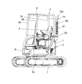
- FIG. 1 is a side view showing a car body of a mini shovel constituting a first embodiment of a working machine according to the present invention
- FIG. 2 is a rear view of a car body provided in the mini shovel shown in FIG. 4 is a plan view of the body of the mini shovel shown in FIG. 1
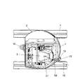
- FIG. 5 is an operator sitting in the driver's seat of the mini shovel shown in FIG. 2A and 2B are diagrams showing the positional relationship between the exhaust pipe and the exhaust pipe, in which FIG. 2A is a rear view and FIG.
- the working machine comprises, for example, a mini-excavator.
- the first embodiment includes a traveling body 1, a revolving unit 2 disposed on the traveling unit 1, and a working device (not shown) supported by a support portion 16 disposed on the front side of the revolving unit 2.
- the work device includes a boom, an arm, a bucket, and the like, and can carry out a digging operation and the like of earth and sand.
- the traveling body 1 and the revolving body 2 described above constitute a vehicle body.
- a driver's seat 3 is disposed on the swing frame 2 a of the swing body 2, and a canopy 4 disposed to cover the driver's seat 3 is provided.
- the canopy 4 is made of, for example, a canopy having four columns. That is, the canopy 4 includes the front right support 5 a, the front left support 5 b, the rear right support 5 c, and the rear left support 5 d.
- the canopy 4 is provided with a roof 6 which is disposed above the columns 5 a to 5 d and covers the driver's seat 3.
- a counterweight 7 for securing a weight balance is provided at a portion of the swing body 2 located behind the driver's seat 3.
- an exhaust pipe 13 having an exhaust port 13a for discharging the exhaust gas of the engine at a position above the counterweight 7 is provided upright.
- an exhaust pipe cover 21 which is disposed so as to surround the circumferential surface of the exhaust pipe 13 and which prevents contact with the exhaust pipe 13 is provided.
- the exhaust pipe 13 and the exhaust pipe 13 are disposed near the virtual straight line 18 connecting the ship point of the driver's seat 3, ie, the seat reference point 17 and the rear left support 5d.
- An exhaust pipe cover 21 is disposed.
- FIG. 6 is a view for explaining the height position of the exhaust port of the exhaust pipe provided in the first embodiment.
- the mini shovel according to the first embodiment has a height dimension of the exhaust pipe 13 and a height dimension 6a1 of the top portion 6a of the roof 6 of the canopy 4 and the bottom portion 6b.
- the height dimension is set to be included in the height area 23 between the height dimension 6b1 and the height dimension 6b1.
- the exhaust pipe 13 is disposed such that the direction of the exhaust port 13a of the exhaust pipe 13 faces, for example, the rear.
- the height dimension from the ground where the mini shovel is installed to the exhaust port 13a of the exhaust pipe 13 is set to a height dimension greater than the average height of an adult, for example, a height dimension greater than 170 cm.
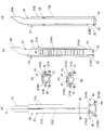
- FIG. 7 is a view showing an exhaust pipe and an exhaust pipe cover provided in the first embodiment, wherein (a) is a front view, (b) is a plan view, and (c) is a perspective view as viewed from the front side; (D) The figure is a perspective view seen from the back side, FIG. 8 is a view showing the exhaust pipe and the exhaust pipe cover provided in the first embodiment, (a) is a rear view, (b) is a (a) BB cross-sectional view of the figure, (c) a cross-sectional view taken along the line CC of the (a) drawing, (d) a cross-sectional view taken along the line AA of the (a) view, (e) the side view.
- the lower end of the exhaust pipe 13 has a hole communicating with the cylindrical portion of the exhaust pipe 13, and is integrally provided with a flange 19 fixed to the upper surface of the counterweight 7. It is The flange 19 is fixed to the upper surface of the counterweight 7 by a bolt 15.
- the lower end portion of the exhaust pipe cover 21 is provided with a notch which forms an opening 30 for permitting insertion of a cleaning tool such as a brush (not shown).
- a cleaning tool such as a brush (not shown).
- the exhaust pipe cover 21 is disposed such that the opening 30 is located, for example, only on the driver's seat 3 side.
- the exhaust pipe cover 21 is disposed with a gap 13 a between itself and the exhaust pipe 13.
- the exhaust pipe covers 21 extend along the extending direction of the exhaust pipe 13 and are disposed to face each other with a gap 21 C so as to sandwich the exhaust pipe 13.
- the first divided cover portion 21A and the second divided cover portion 21B are included.
- the above-mentioned notches are a first notch 21A2 formed at the lower end of the first divided cover 21A, and a second notch 21B2 formed at the lower end of the second divided cover 21B. It consists of
- the first divided cover portion 21A and the second divided cover portion 21B each have a flat plate-shaped first mounting portion 21A3 and a second mounting portion 21B3 attached to the upper surface of the counterweight 7 at lower ends thereof.
- the attachment portions 21A3 and 21B3 are fastened together with the flange 19 of the exhaust pipe 13 by the above-described bolt 15 and fixed to the counterweight 7.
- a large number of slits 21A1 are formed on the side surface of the first divided cover portion 21A.
- a large number of slits are formed on the side surface of the second divided cover portion 21B.
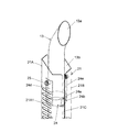
- FIG. 9 is an enlarged perspective view showing upper portions of the exhaust pipe and the exhaust pipe cover provided in the first embodiment
- FIG. 10 is a view showing a cover holding portion provided in the first embodiment
- FIG. (B) is a perspective view showing the cover holding portion attached to the exhaust pipe
- FIG. 11 is a view showing the cover holding portion provided in the first embodiment
- a) The figure is an enlarged perspective view showing a state in which the cover holding portion is attached to the exhaust pipe
- (b) is an enlarged plan view showing the state in which the cover holding portion is attached to the exhaust pipe
- FIG. 12 is provided in the first embodiment It is a disassembled perspective view which shows the attachment relation of an exhaust pipe and an exhaust pipe cover.
- the cover holding portion 24 for holding the exhaust pipe cover 21 on the exhaust pipe 13 is provided.
- the cover holding portion 24 is, as shown in FIG. 11B, an annular member 24a disposed with a gap 13b with the exhaust pipe 13 so as to surround the circumferential surface of the exhaust pipe 13, and the annular member 24a is supported, and a support member described later fixed by welding, for example, around the exhaust pipe 13, a standing member fixed to the annular member 24a by welding, for example, extended in the vertical direction, and the standing member And an attachment means for attaching the exhaust pipe cover 21 thereto.
- the annular member 24a is welded to the support member.
- the above-described support members are composed of a pair of support members 24 b and 24 c disposed to face each other with the exhaust pipe 13 interposed therebetween.
- the erecting members described above are disposed to face each other with the exhaust pipe 13 interposed therebetween, and each of the first divided cover portion 21A or the second divided cover portion 21B of the exhaust pipe cover 21 is attached and bent. It consists of standing members 24d and 24e.
- the pair of support members 24 c and 24 d are disposed, for example, in the upper portion of the exhaust pipe 13. Lower portions of the pair of upright members 24d and 24e are fixed by, for example, welding to an annular member 24a supported by the support members 24c and 24d.
- Attached members 24f and 24g having female threads are fixed to the upper portions of the upright members 24d and 24e, respectively, and corresponding bolts 25 shown in FIG. 9 are attached to the female threads of the attached members 24f and 24g.
- the attachment members 24f and 24g and the bolts 25 constitute attachment means for attaching the first divided cover portion 21A and the second divided cover portion 21B included in the exhaust pipe cover 21 to the upright members 24d and 24e.
- the pair of support members 24b and 24c and the pair of upright members 24d and 24e are disposed to be orthogonal to each other in plan view. Further, one cover holding portion 24 having the above-described configuration is provided, and the upper portions of the first divided cover portion 21A and the second divided cover portion 21B are held by the cover holding portion 24 as described above. Lower ends of the cover portion 21A and the second divided cover portion 21B, that is, the first and second attachment portions 21A3 and 21B3 are fixed to the counterweight 7 as described above.
- the upper surface 7b of the counterweight 7 is formed with a hole 7C to which the exhaust gas of the engine is introduced, and a plurality of bolt holes 7b1 are formed around the hole 7C.
- the holes 19a formed in the flange 19 of the exhaust pipe 13 and the holes formed in the first mounting portion 21A3 of the first divided cover portion 21A are fitted to the bolt holes 7b1 of the upper surface 7b of the counterweight 7, and the exhaust pipe
- a hole 19a formed in the flange 19 of 13 and a hole formed in the second attachment portion 21B3 of the second divided cover portion 21B are fitted to the other bolt holes 7b1 on the upper surface of the counterweight 7, and
- the first divided cover portion 21A and the second divided cover portion 21B and the exhaust pipe 13 are fastened, and the first divided cover portion 21A and the second divided cover portion 21B and the exhaust pipe 13 are illustrated on the counterweight 7 as shown in FIG.
- it is fixed in a self-supporting state so as not to contact the canopy 4, and is set up and held.
- FIG. 13 is a cross-sectional view of an essential part showing an arrangement relationship between a tail pipe and an exhaust pipe provided in the first embodiment.
- a muffler 10 for guiding and muffling exhaust gas of an engine (not shown) and a tail pipe 11 for guiding the exhaust gas discharged from the muffler 10 are disposed.
- a passage 7a communicating with the hole 7c of the counterweight 7 shown in FIG. 12 described above is formed in the counterweight 7.
- the tail pipe 11 is inserted into the passage 7 a so as not to contact the wall surface of the counterweight 7 forming the passage 7 a, and the upper end 11 a is inserted into the exhaust pipe 13.
- the exhaust gas of the engine is guided to the exhaust pipe 13 through the muffler 10 and the tail pipe 11, and the exhaust port 13 a of the exhaust pipe 13 is externally transmitted at a position above the counterweight 7. Released.
- the first embodiment when the operator 22 sitting in the driver's seat 3 tries to visually check the rear, the seat reference point 17 of the driver's seat 3 and the driving The exhaust pipe 13 is completely or almost completely hidden behind the rear left support 5d located on an imaginary straight line 18 connecting the rear left support 5d standing on the rear side of the seat 3. Become. Therefore, although the operator 22 who sits in the driver's seat 3 is blocked by the rear left support 5d, it is less likely to be blocked by the exhaust pipe 13, thereby improving the workability of the work performed by the mini shovel be able to. In addition, since the first embodiment can secure a good rear view, it is possible to secure the safety for a structure or a person present behind the mini shovel.
- the exhaust pipe 13 is heated by the exhaust gas being introduced, but the radiation heat from the surface of the exhaust pipe 13 is provided behind the driver's seat 3 and the rear left support It is interrupted by 5d. As a result, it is possible to prevent the operator 22 seated in the driver's seat 3 from having an unpleasant warmth due to the heat of the exhaust gas. Therefore, in the case of a working machine provided with the above-described exhaust gas processing device in which the temperature of the exhaust gas tends to be high, the surface temperature of the exhaust pipe 13 also tends to be high. As described above, the first embodiment is also suitable as a mini-excavator in which the surface temperature of the exhaust pipe 13 is high and the radiation heat is high.
- the lower end portion of the first and second divided cover portions 21A and 21B included in the exhaust pipe cover 21 is formed with the opening 30 for permitting the insertion of the cleaning tool such as a brush or the like. Since the first and second notched portions 21A2 and 21B2 are formed, dust such as dead leaves infiltrates from the gap 13b between the exhaust pipe 13 and the first and second divided cover portions 21A and 21B. , Lower end portions of the second divided cover portions 21A and 21B, the lower ends of the first and second divided cover portions 21A and 21B without disassembling the first and second divided cover portions 21A and 21B.
- the first embodiment is provided with the exhaust gas treatment apparatus, and the temperature of the exhaust gas is likely to be high, and as a mini-excavator particularly required to prevent the contact of the refuse such as dead leaves with the exhaust pipe 13 Is also suitable. Furthermore, this first embodiment is suitable for a mini-excavator often used in a work environment where waste such as dead leaves is likely to be produced, such as in a town.
- the opening 30 formed by the first and second notches 21A2 and 21B2 of the first and second divided cover portions 21A and 21B is located only on the driver's seat 3 side. Since the first and second divided cover portions 21A and 21B are disposed to make the opening portion 30 be hidden by the driver's seat 3, the contact to the heated exhaust pipe 13 is It can prevent.
- the dust in the clearance along with the dust accumulated in the opening 30 may be a brush or the like. It can be cleaned and removed by a cleaning tool.
- the heat of the exhaust pipe 13 due to the exhaust gas can be dissipated from the gap 21C formed between the first divided cover portion 21A and the second divided cover portion 21B.
- the heat of the exhaust pipe 13 between the exhaust pipe 13 and the first and second divided cover portions 21A and 21B can prevent the first and second divided cover portions 21A and 21B from being heated.
- dust such as dead leaves which enter from the gap 21C of the first and second divided cover portions 21A and 21B and accumulated near the lower end portions of the exhaust pipe 13 and the first and second divided cover portions 21A and 21B is also an opening portion. It can be easily cleaned and removed by inserting a cleaning tool such as a brush at 30.
- the exhaust pipe cover 21 including the first divided cover portion 21A and the second divided cover portion 21B can be stably erected. It can be held.
- the supporting members 24b and 24c fixed to the circumferential surface of the exhaust pipe 13, the annular member 24a supported by the supporting members 24b and 24c, and the annular member 24a are fixed.
- the first and second divided cover portions are constituted by the erected members 24d and 24e and the attachment members 24f and 24g for attaching the first and second divided cover portions 21A and 21B to the erected members 24d and 24e and the bolt 25. 21A and 21B can be stably held.
- the heat of the exhaust pipe 13 heated by the exhaust gas is transmitted to the support members 24 b and 24 c fixed to the circumferential surface of the exhaust pipe 13, and the exhaust from these support members 24 b and 24 c is performed.
- the annular member 24a arranged with a gap 13b between the tube 13 and the annular member 24a is further fixed to the annular member 24a from the annular member 24a, and is attached to the vertically disposed extending members 24d and 24e. , And transmitted to the second divided cover portions 21A and 21B.
- the heat transferred from the exhaust pipe 13 to the support members 24b and 24c is mainly cooled after being cooled at the portion of the annular member 24a located between the support members 24b and 24c and the standing members 24d and 24e.
- the heat insulating material and the long body are disposed so as to surround the exhaust pipe 13 with the heat transmitted from the exhaust pipe 13 to the first and second divided cover portions 21A and 21B. It can be lowered without requiring the cylindrical member to be formed. Therefore, the safety at the time of contacting the first and second divided cover portions 21A and 21B provided in the first embodiment is secured.
- the first and the second members are disposed via the annular member 24a disposed with a gap 13b between the exhaust pipe 13 and the first and the second embodiments without using the heat insulating material and the cylindrical member forming the long body.
- the exhaust pipe 13 can hold the second divided cover portions 21A and 21B.
- the first embodiment can realize a simple structure of the exhaust pipe cover holding structure and can reduce the manufacturing cost.
- the first divided cover portion 21A included in the exhaust pipe cover 21 is supported by a pair of supporting members 24b and 24c that are fixed to the exhaust pipe 13, and these supporting members 24b and 24c. It can be attached to the exhaust pipe 13 via the annular member 24a and the upright member 24d of the pair of upright members 24d and 24e fixed to the annular member 24a. Further, a pair of support members 24b and 24c fixing the second divided cover portion 21B to the exhaust pipe 13, an annular member 24a supported by the support members 24b and 24c, and a standing installation provided to the annular member 24a It can be attached to the exhaust pipe 13 via the member 24e.
- each of the pair of erected members 24d and 24c is bent, it is possible to ensure relatively high strength.
- the first cover portion 21A and the second cover portion 21B included in the exhaust pipe cover 21 can be stably erected and held on the exhaust pipe 13.
- the first and second divided cover portions 21A and 21B are also formed. Since the slits 21A1 and the like are formed on the side surface of the exhaust pipe 13, the heat of the exhaust pipe 13 does not stay between the first divided cover portion 21A and the second divided cover portion 21B and the exhaust pipe 13, and the heat of the exhaust pipe 13 is Can be dissipated to the outside through the gap 21C and the slit 21A. Accordingly, the heating of the first and second divided cover portions 21A and 21B due to such stagnant heat can be suppressed.
- the pair of support members 24b and 24c are fixed to the upper portion of the exhaust pipe 13, and the pair of upright members 24d and 24e are formed on the annular member 24a supported by the support members 24b and 24c.
- the lower part of the is fixed.
- the mounting position of the exhaust pipe cover 21 in the cover holding portion 24 can be set to a high position at the top of the exhaust pipe 13.
- the lower part of the exhaust pipe 13 is located in the vicinity of the introduction part of the exhaust gas discharged from the muffler 10, and the temperature of the lower part becomes high due to the high temperature of the exhaust gas.
- the temperature of the upper portion of the exhaust pipe 13 is lower than that in the lower portion due to the temperature decrease accompanying the rise of the exhaust gas.
- the heat of the upper part of the exhaust pipe 13 whose temperature has dropped in this way is contained in the exhaust pipe cover 21 through the support members 24b and 24c, the annular member 24a, and the standing members 24d and 24e.
- the temperature of the first and second divided cover portions 21A and 21B attached to the exhaust pipe 13 by the cover holding portion 24 can be suppressed to a relatively low level.
- the pair of support members 24b and 24c and the pair of upright members 24d and 24e are disposed to be orthogonal to each other in a plan view.
- the first divided cover portion 21 A side and the second Since the portions of the annular member 24a positioned on the divided cover portion 21B side and the pair of standing members 24d and 24e are arranged symmetrically with respect to the above-mentioned center line, a stable weight balance on the left and right is ensured.
- the heat transfer path transmitted from the support members 24b and 24c to the first divided cover portion 21A or the second divided cover portion 21B via the annular member 24a and the standing members 24d and 24e may be a relatively long path. This contributes to lowering the temperature of the first and second divided cover portions 21A and 21B.
- the upper portions of the first and second divided cover portions 21A and 21B are held by the cover holding portion 24 and the lower portions are fixed to the counterweight 7, respectively.
- the first and second divided cover portions 21A and 21B can be stably erected and held in a self-supporting state which does not contact surrounding members as described above. Therefore, the first and second divided cover portions 21A and 21B can be cooled by the air surrounding the first and second divided cover portions 21A and 21B, and the heat of the first and second divided cover portions 21A and 21B is Transmission to the surrounding members is prevented. Further, the provision of only one cover holding portion 24 which tends to increase the number of members contributes to the reduction of the manufacturing cost.
- the height dimension of the exhaust pipe 13 is set to the height dimension at which the exhaust port 13a is disposed between the uppermost portion 6a and the lowermost portion 6b of the roof 6 of the canopy 4. It is Since the exhaust gas discharged from the exhaust port 13a of the exhaust pipe 13 is intercepted by the portion between the top 6a and the bottom 6b of the canopy 6 at the time of the turning of the turning body 2 and the like with this configuration, It is possible to reduce the inflow of exhaust gas in the three directions of the seat.
- the first embodiment is particularly suitable as a mini-excavator equipped with an exhaust gas treatment device.
- the exhaust pipe 13 can be made not to protrude from the roof 6 of the canopy 4 in the first embodiment, the restriction due to the height restriction received when carrying the mini-excavator on the trailer and the like is relieved. It can be done. Further, in the first embodiment, when trying to enter from the entrance of the building in order to carry out the work in the building, as long as the height of the entrance is higher than the height of the roof 6, the exhaust pipe 13 is You can enter the building without hitting the top of the entrance. That is, in the first embodiment, restrictions at the time of transportation of the mini excavator and at the time of work in the building can be alleviated.
- the exhaust pipe 13 is disposed so that the exhaust port 13a is directed rearward, the emitted exhaust gas is operated with the discharge direction of the exhaust gas as the opposite direction to the driver's seat 3. It can be made not to flow in the seat 3 direction.
- the height dimension from the ground on which the mini shovel is installed to the exhaust port 13a of the exhaust pipe 13 is set to a height dimension greater than the average height of an adult. It is possible to realize protection from exhaust gas for people present in the surroundings.
- the counterweight 7 is provided with a passage 7a into which the tail pipe 11 is inserted, and the upper end 11a of the tail pipe 11 is inserted into the exhaust pipe 13. Therefore, the exhaust gas led from the muffler 10 to the tail pipe 11 is not radiated to the wall surface forming the passage 7 a of the counter weight 7, and between the tail pipe 11 and the wall surface forming the passage of the counter weight 7. There is a gap in the From these things, the counterweight 7 is not directly heated, and the temperature rise of the counterweight 7 due to the exhaust gas can be suppressed to be low. Therefore, while the exhaust gas is released from the exhaust pipe 13, it is possible to prevent the discomfort due to the contact with the counterweight 7.
- FIG. 14 is a side view showing a vehicle body of a mini shovel constituting a second embodiment of a working machine according to the present invention
- FIG. 15 is a rear view of a vehicle body of the mini shovel shown in FIG.
- FIG. 17 is a plan view showing the body of the mini shovel shown in FIG. 14 with the roof of the cab removed
- FIG. 18 is a perspective view of the body of the mini shovel shown in FIG. It is.
- the working machine according to the second embodiment is also composed of, for example, a mini-excavator, and includes a traveling body 41 constituting a vehicle body and a revolving body 42. It has a support 56 to which a working device is attached.
- the work device includes a boom, an arm, a bucket, and the like, and can carry out a digging operation and the like of earth and sand.
- a counterweight 47 for securing weight balance is provided at a portion of the swing body 2 located behind the driver's cab 44.
- An exhaust pipe 53 (described later) having an exhaust port 53a for discharging the exhaust gas of the engine above the counterweight 47 is erected and held by the counterweight 47 in a state of being separated from the operation room 44.
- an exhaust pipe cover 61 which is disposed so as to surround the periphery and upper portion of an exhaust pipe 53 described later and which prevents the exhaust pipe 53 from being in contact with the exhaust pipe 53 is provided.
- FIG. 19 is a view showing an exhaust pipe and an exhaust pipe cover provided in the second embodiment, where (a) is a front view, (b) is a plan view, and (c) is a perspective view seen from the front side; (D) The figure is a perspective view seen from the back side, FIG. 20 is a view showing an exhaust pipe and an exhaust pipe cover provided in the second embodiment, (a) a rear view, (b) a (a) FIG. 6A is a cross-sectional view, FIG. 6C is a cross-sectional view of FIG. 4A, FIG. 4D is a cross-sectional view of FIG. 4A, and FIG.
- the lower end of the exhaust pipe 53 has a hole communicating with the cylindrical portion of the exhaust pipe 53, and is integrally provided with a flange 59 fixed to the upper surface of the counterweight 47. It is The flange 59 is fixed to the upper surface of the counterweight 47 by a bolt 55.
- the lower end portion of the exhaust pipe cover 61 is provided with a notch which forms an opening 70 for allowing the insertion of a cleaning tool such as a brush (not shown).
- a cleaning tool such as a brush (not shown).
- the exhaust pipe cover 61 is disposed such that the above-described opening 70 is located only on the side of the cab 44 where the driver's seat 43 is disposed, for example.
- the exhaust pipe cover 61 is extended along the extending direction of the exhaust pipe 53, and the first divided cover portion 61A and the second divided cover are disposed to face each other with a gap 61C so as to sandwich the exhaust pipe 53. And 61B.
- the above-mentioned notch is composed of a first notch 61A2 formed at the lower end of the first divided cover 61A and a second notch 61B2 formed at the lower end of the second divided cover 61B.
- the first divided cover portion 61A and the second divided cover portion 61B each have a flat plate-shaped first mounting portion 61A3 and a second mounting portion 61B attached to the upper surface of the counterweight 47 at lower ends thereof.
- the mounting portions 61A3 and 61B3 are fixed together with the flange 59 of the exhaust pipe 53 by the above-described bolt 55 and fixed to the counterweight 47.
- a large number of slits 61A1 are formed on the side surface of the first divided cover portion 61A.
- a large number of slits are formed on the side surface of the second divided cover portion 61B.
- a connector 62 is, for example, integrally welded to the first divided cover portion 61A.
- the connector 62 and the second divided cover portion 61B are fastened by bolts 63.
- FIG. 21 is a plan view of relevant parts showing an arrangement relationship between a tail pipe and an exhaust pipe provided in the second embodiment.
- the exhaust gas of the engine (not shown) is guided and muffled on the revolving frame 42a of the revolving structure 42, and the exhaust gas discharged from the muffler 50 as in the first embodiment.
- a tail pipe 51 for guiding gas is disposed.
- a passage 47 a is formed in the counterweight 47.
- the tail pipe 51 is inserted into the passage 47 a so as not to contact the wall surface of the counterweight 47 forming the passage 47 a, and the upper end 51 a is inserted into the exhaust pipe 53.
- the exhaust gas of the engine is discharged from the exhaust port 53a of the exhaust pipe 53 via the muffler 50 and the tail pipe 51, as in the first embodiment.
- the second embodiment when the operator sitting on the driver's seat 43 in the driver's cab 44 tries to visually check the rear, the second embodiment also has the seat reference point 57 of the driver's seat 43 and the driver's seat 43
- the exhaust pipe 53 is completely or almost completely hidden behind the rear left support column 45 located on an imaginary straight line 58 connecting the rear left support column 45 standing on the rear side of the rear cover. Therefore, the operator sitting on the driver's seat 43 is less likely to be blocked by the exhaust pipe 53, and a good backward visibility can be secured. Thereby, the same operation and effect as the first embodiment can be obtained.
- the second embodiment is also suitable for a mini-excavator which is provided with an exhaust gas treatment device and in which the radiant heat of the exhaust pipe 53 tends to be high.
- an opening 70 for permitting insertion of a cleaning tool such as a brush is formed at the lower end portion of the first and second divided cover portions 61A and 61B included in the exhaust pipe cover 61. Since the second notches 61A2 and 61B2 are formed, dust such as dead leaves intrudes from the gap 53b between the exhaust pipe 53 and the first and second divided cover parts 61A and 61B. When it accumulates near the lower end part of 2 division cover parts 61A and 61B, cleaning of the brush etc. is carried out to opening 70 like 1st embodiment, without disassembling 1st, 2nd division cover parts 61A and 61B. By inserting the tool, the dust can be easily cleaned and removed, and the same function and effect as the first embodiment can be obtained.
- a cleaning tool such as a brush
- the exhaust pipe 13 and the exhaust pipe cover 21 are disposed in the vicinity of a virtual straight line 18 connecting the seat reference point 17 of the driver's seat 3 and the rear left support 5d of the canopy 4
- the exhaust pipe 13 and the exhaust pipe cover 21 may be disposed on the straight line 18.
- the exhaust pipe 53 and the exhaust pipe cover 61 are disposed on a virtual straight line 58 connecting the seat reference point 57 of the driver's seat 43 and the rear left support 45 included in the cab 44
- the exhaust pipe 53 and the exhaust pipe cover 61 may be arranged near the virtual straight line 58.
- the exhaust pipe 13 and the exhaust pipe cover 21 are disposed in the vicinity of a virtual straight line 18 connecting the seat reference point 17 of the driver's seat 3 and the rear left support 5d of the canopy 4
- the exhaust pipe 13 and the exhaust pipe cover 21 are disposed on a virtual straight line connecting the seat reference point 17 of the driver's seat 3 and the rear right support 5 c of the canopy 4 or at a position near the virtual straight line. It may be configured.
- the exhaust pipe 53 and the exhaust are disposed on a virtual straight line 58 connecting the seat reference point 57 of the driver's seat 43 in the cab 44 and the rear left support 45 included in the cab 44
- the pipe cover 61 is disposed, the exhaust pipe is located on a virtual straight line connecting the seat reference point 57 of the driver's seat 43 and the rear right support included in the cab 44 or at a position near the virtual straight line. 53 and the exhaust pipe cover 61 may be disposed. Those configured as described above can also ensure a good rearward visibility of the operator or the like seated in the driver's seat 3, 43.
- the exhaust pipe 13 is disposed such that the exhaust port 13a is directed to the rear of the cab 3, but even if the exhaust pipe 13 is disposed such that the exhaust port 13a is directed to the side. Good.
- the exhaust pipe 53 may be disposed so that the exhaust port 53a faces the rear of the driver's cab 44 or faces the side of the driver's cab 44.
- the said 1st Embodiment provided only one cover holding part 24 which hold
- the lower end part of the exhaust pipe cover 21 is a counterweight
- the exhaust pipe cover 21 may be configured to be held on the exhaust pipe 13 by the cover holding portions 24 provided on both the upper portion and the lower portion of the exhaust pipe 13 without being fixed to 7.
- the working machine which concerns on the said, 1st, 2nd embodiment consists of a mini shovel, respectively, this invention is not limited to a mini shovel.
- the present invention is also applicable to working machines such as hydraulic excavators which are larger than mini excavators.
Landscapes
- Engineering & Computer Science (AREA)
- Mining & Mineral Resources (AREA)
- Civil Engineering (AREA)
- General Engineering & Computer Science (AREA)
- Structural Engineering (AREA)
- Mechanical Engineering (AREA)
- Chemical & Material Sciences (AREA)
- Combustion & Propulsion (AREA)
- Transportation (AREA)
- Component Parts Of Construction Machinery (AREA)
- Cooling, Air Intake And Gas Exhaust, And Fuel Tank Arrangements In Propulsion Units (AREA)
- Exhaust Silencers (AREA)
Description
本発明は、エンジンの排気ガスを車体の上方位置において放出する排気管を備えたミニショベル等の作業機械に関する。
ミニショベル等の小型の作業機械では、造園や配管工事等のために比較的狭い作業場所で活用されることが多い。このような狭い作業場所にあっては、排気管の排気口が車体の下方側に位置すると、当該作業機械の周囲に存在する比較的低い植木や高さの低い構造物に向かって排気ガスが放出され、これらの植木や構造物に悪影響を及ぼしやすい。
このようなことから、ミニショベル等の小型の作業機械にあって、エンジンの排気ガスを上方位置で放出する排気管を備えたものがある。この排気管は運転席が配置されるキャビンすなわち運転室の右側方の後部付近に配置されている。
上述した特許文献1に示される従来技術は、排気管を運転席の右側方の後部付近に配置してあることから、運転席に座ったオペレータが右後方を目で確認しようとするとき、排気管が視界に入り、すなわち排気管が障害物となり、良好な後方視界を確保し難い問題がある。
本発明は、上述した従来技術における実状からなされたもので、その目的は、運転席に座ったオペレータの良好な後方視界を確保することができる作業機械を提供することにある。
この目的を達成するために、本発明は、旋回体と、この旋回体に取り付けた作業装置と、上記旋回体上に配置した運転席と、この運転席の後方に配置したカウンタウェイトと、上記旋回体上に配置され、エンジンの排気ガスが導かれるマフラと、このマフラから排出された排気ガスを上記カウンタウェイトの上方位置で放出させる排気口を有する排気管を備えた作業機械において、上記運転席の後側に立設する複数の支柱を備え、上記運転席の座席基準点と上記複数の支柱のうちのいずれかの支柱とを結ぶ仮想的な直線上、または上記仮想的な直線の近傍位置に、上記排気管を配置したことを特徴としている。
本発明は、運転席に座ったオペレータが後方を目で確認しようとするとき、運転席の座席基準点と、運転席の後側に立設する該当する支柱とを結ぶ仮想的な直線上に位置する当該支柱の背後に排気管が完全に、あるいは略完全に隠れた状態になる。したがって、運転席に座ったオペレータは支柱によって視界が遮られるものの、排気管によって視界を遮られることは少なくなり、良好な後方視界を確保することができる。
また本発明は、排気ガスが導かれることによって排気管が熱くなるが、この排気管の表面からの輻射熱が上述の運転席の背後に立設された支柱によって遮られる。これにより、運転席に着座したオペレータに対して、排気ガスの熱による不快な暖かさを与えないようにすることができる。昨今、排気ガス処理装置を備えた油圧ショベル等の作業機械が開発されてきているが、排気ガス処理装置を備えていない作業機械の排気ガス温度が300℃程度であったものが、排気ガス処理時にNOxやPM(粒子状物質)の燃焼に伴って生じる高熱により、排気ガス温度が600℃位まで上昇することが知られている。したがって、このような排気ガス処理装置を備えた作業機械にあっては、排気管の表面温度も高くなりやすい。このように排気管の表面温度が高くなり、上述した輻射熱が高くなりやすい作業機械に、本発明は特に有効である。
また本発明は、当該作業機械がミニショベルから成り、上記複数の支柱が、上記旋回体上に配置される運転室に含まれる支柱、または旋回体上に配置されるキャノピに含まれる支柱から成ることを特徴としている。
このように構成した本発明は、運転席に座ったオペレータが後方を目で確認しようとするとき、運転室に含まれる支柱、またはキャノピに含まれる支柱の背後に排気管が完全に、あるいは略完全に隠れた状態になる。したがって後方視界の良好なミニショベルを実現させることができる。すなわち、ミニショベルの運転室に含まれる支柱、あるいはミニショベルのキャノピに含まれる支柱を、運転席に座ったオペレータが後方を見るときに、排気管を見えなくする、あるいは見えにくくする構造物として有効に活用することができる。また、キャノピを備えたミニショベルにあっては、運転室の背後に立設する支柱によって排気管の表面からの輻射熱が上述の運転席に及ぶことを防ぐことができる。
また本発明は、上記排気管への接触を防ぐ排気管カバーを備え、上記排気管カバーの下端部分に、清掃具の挿入を許容させる開口部を形成する切り欠き部を設けたことを特徴としている。
このように構成した本発明は、排気管と排気管カバーとの隙間から枯葉等のゴミが侵入し、下端部付近に溜まった場合には、排気管カバーを分解することなく排気管カバーの下端部分に形成した切り欠き部によって設けられた空間部にブラシ等の清掃具を挿入して、それらのゴミを簡単に清掃除去することができる。本発明は、このようにゴミを簡単に清掃除去できることにより、ゴミが熱せられた排気管に接触して燃やされることを容易に防ぐことができる。
また本発明は、上記排気管カバーを上記排気管に保持させるカバー保持部を備え、上記カバー保持部は、上記排気管の周面を囲むように上記排気管との間に隙間をもって配置した環状部材と、この環状部材を支持し上記排気管の周面に固定した支持部材と、上記環状部材に固定され、上下方向に延設させた立設部材と、この立設部材に上記排気管カバーを取り付ける取り付け手段とを備えたことを特徴としている。
このように構成した本発明は、排気ガスによって熱せられた排気管の表面の熱が排気管の周面に固定した支持部材に伝えられ、この支持部材から排気管との間に隙間をもって配置した環状部材に伝えられ、さらにこの環状部材から当該環状部材に固定され、上下方向に延設させた立設部材に伝えられ、立設部材から取り付け手段を介して当該立設部材に取り付けられる排気管カバーに伝えられる。したがって、排気管から支持部材に伝えられた熱は主に、支持部材と立設部材の間に位置する環状部材の部分で冷やされた後、環状部材に取り付けられた立設部材の部分と、排気管カバーが取り付けられる取り付け手段が設けられる立設部材の部分との間で冷やされて、立設部材から取り付け手段を介して排気管カバーへと伝えられる。これらにより、排気管から排気管カバーへと伝えられる排気ガスによる熱を排気管を囲むように配置される断熱材や長尺体を形成する筒状部材を要することなく下げることができる。また本発明は、断熱材や、長尺体から成る筒状部材を要さずに環状部材を介して排気管カバーを排気管に保持させるようにしたことから、構造の簡単な排気管カバー保持構造を実現させることができる。
また本発明は、上記作業機械が、上記旋回体上に配置され、上記運転席の上方を覆うルーフを有するキャノピを備えたミニショベルから成り、上記排気管の高さ寸法を、上記排気口が上記キャノピの上記ルーフの最上部と最下部の間に配置される高さ寸法に設定したことを特徴としている。
このように構成した本発明は、排気管の排気口から放出した排気ガスが旋回体の旋回時等にキャノピのルーフの最上部と最下部との間に位置する部分によって遮られ、運転席方向に放散されることを防ぐことができる。これにより、排気管の排気口から放出した排気ガスに伴う運転席に着座したオペレータの不快感を抑えることができる。
また本発明は、排気管をキャノピのルーフより上方に突出させないようにすることができるので、トレーラに当該作業機械を乗せて運搬する際の高さ規制による制約を受けないようにすることができる。また本発明は、建物内作業を行うために建物の入口から進入させようとするときに、排気管を入口の上部に当たらないようにすることができる。
本発明は、運転席の後側に立設する複数の支柱を備え、運転席の座席基準点と、上述した複数の支柱のうちのいずれかの支柱とを結ぶ仮想的な直線上、または仮想的な直線の近傍位置に、エンジンの排気ガスをカウンタウェイトの上方位置で放出する排気管を配置した構成にしてあることから、運転席に座ったオペレータが後方を目で確認しようとするときに、排気管が該当する支柱の背後に隠れた状態とすることができる。これにより本発明は、運転席に座ったオペレータの良好な後方視界を確保することができ、従来に比べて当該作業機械で実施される作業の作業性を向上させることができる。また本発明は、良好な後方視界を確保できることから、当該作業機械の後方に存在する構造物や人に対する安全性を確保することができる。これらのことから本発明は、町中等の狭い場所で作業が行われることの多いミニショベルにも好適である。
以下、本発明に係る作業機械の実施の形態を図に基づいて説明する。
図1は本発明に係る作業機械の第1実施形態を構成するミニショベルの車体を示す側面図、図2は図1に示すミニショベルに備えられる車体の背面図、図3は図1に示すミニショベルの車体を斜め前方から見た斜視図、図4は図1に示すミニショベルの車体の平面図、図5は図1に示すミニショベルの運転席に座ったオペレータと、後側左支柱及び排気管の位置関係を示す図で、(a)図は背面図、(b)図は平面図である。
図1~4に示すように、第1実施形態に係る作業機械は、例えばミニショベルから成っている。この第1実施形態は、走行体1と、この走行体1上に配置される旋回体2と、この旋回体2の前側に配置された支持部16に支持される図示しない作業装置とを備えている。作業装置は、ブーム、アーム、バケット等を備え、土砂の掘削作業等を実施することができる。上述した走行体1と旋回体2は車体を構成している。
旋回体2の旋回フレーム2a上には、運転席3が配置され、この運転席3を覆うように配置されるキャノピ4を設けてある。キャノピ4は、例えば4柱を有するキャノピから成っている。すなわち、キャノピ4は、前側右支柱5aと、前側左支柱5bと、後側右支柱5cと、後側左支柱5dとを備えている。また、このキャノピ4は、支柱5a~5dの上部に配置され、運転席3を覆うルーフ6を備えている。
運転席3の後側に位置する旋回体2の部分には、重量バランスを確保するカウンタウェイト7を設けてある。このカウンタウェイト7には、エンジンの排気ガスをカウンタウェイト7の上方位置で放出する排気口13aを有する排気管13を立設させてある。また、排気管13の周面を囲むように配置され、排気管13への接触を防ぐ排気管カバー21を備えている。
この第1実施形態は、図4に示すように、運転席3のシップポイントすなわち座席基準点17と、例えば後側左支柱5dとを結ぶ仮想的な直線18の近傍位置に、排気管13及び排気管カバー21を配置してある。これにより、図5に示すように、運転席3にオペレータ22が着座した際には、排気管13及び排気管カバー21がオペレータの背後に位置する状態となる。
図6は第1実施形態に備えられる排気管の排気口の高さ位置を説明する図である。
この第1実施形態に係るミニショベルは、図6に示すように、排気管13の高さ寸法を、排気口13aがキャノピ4のルーフ6の最上部6aの高さ寸法6a1と、最下部6bの高さ寸法6b1との間の高さ領域23に含まれるような高さ寸法に設定してある。排気管13の排気口13aの向きが例えば後方を向くように、この排気管13を配置してある。当該ミニショベルが設置される地面から排気管13の排気口13aまでの高さ寸法は、大人の平均身長以上の高さ寸法、例えば170cm以上の高さ寸法に設定してある。
図7は第1実施形態に備えられる排気管及び排気管カバーを示す図で、(a)図は正面図、(b)図は平面図、(c)図は正面側から見た斜視図、(d)図は背面側から見た斜視図、図8は第1実施形態に備えられる排気管及び排気管カバーを示す図で、(a)図は背面図、(b)図は(a)図のB-B断面図、(c)図は(a)図のC-C断面図、(d)図は(a)図のA-A断面図、(e)図は側面図である。
これらの図7,8に示すように、排気管13の下端には、排気管13の筒状部に連通する穴部を有し、カウンタウェイト7の上面に固定されるフランジ19を一体に設けてある。このフランジ19は、ボルト15によってカウンタウェイト7の上面に固定される。
この第1実施形態は、排気管カバー21の下端部分に、図示しないブラシ等の清掃具の挿入を許容させる開口部30を形成する切り欠き部を備えている。図1に示すように、開口部30が、例えば運転席3の側にのみ位置するように排気管カバー21を配置してある。この排気管カバー21は、排気管13との間に隙間13aをもって配置してある。
同図7,8に示すように、排気管カバー21は、それぞれ排気管13の延設方向に沿うように延設され、排気管13を挟むように互いに隙間21Cをもって対向して配置される第1分割カバー部21Aと第2分割カバー部21Bとを含んでいる。また、上述した切り欠き部は、第1分割カバー部21Aの下端部分に形成される第1切り欠き部21A2と、第2分割カバー部21Bの下端部分に形成される第2切り欠き部21B2とから成っている。第1分割カバー部21Aと第2分割カバー部21Bは、それぞれの下端にカウンタウェイト7の上面に取り付けられる平板状の第1取付け部21A3、第2取り付け部21B3を備えている。これらの取り付け部21A3,21B3は、上述したボルト15によって排気管13のフランジ19と共締めされてカウンタウェイト7に固定されるようになっている。なお、第1分割カバー部21Aの側面には、多数のスリット21A1を形成してある。同様に、第2分割カバー部21Bの側面にも多数のスリットを形成してある。
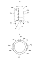
図9は第1実施形態に備えられる排気管及び排気管カバーのそれぞれ上方部分を示す拡大斜視図、図10は第1実施形態に備えられるカバー保持部を示す図で、(a)図はカバー保持部を分解して示した斜視図、(b)図はカバー保持部を排気管に取り付けた状態を示す斜視図,図11は第1実施形態に備えられるカバー保持部を示す図で、(a)図はカバー保持部を排気管に取り付けた状態を示す拡大斜視図、(b)図はカバー保持部を排気管に取り付けた状態を示す拡大平面図、図12は第1実施形態に備えられる排気管及び排気管カバーの取り付け関係を示す分解斜視図である。
この第1実施形態は、図9~12に示すように、排気管カバー21を排気管13に保持させるカバー保持部24を備えている。このカバー保持部24は、図11の(b)図に示すように、排気管13の周面を囲むように、排気管13との間に隙間13bをもって配置した環状部材24aと、この環状部材24aを支持し、排気管13の周囲に例えば溶接によって固定した後述の支持部材と、環状部材24aに例えば溶接によって固定され、上下方向に延設させた後述の立設部材と、この立設部材に排気管カバー21を取り付ける取り付け手段とを備えている。なお例えば、環状部材24aは支持部材に溶接してある。
上述した支持部材は、排気管13を挟んで互いに対向するように配置した一対の支持部材24b,24cから成っている。上述した立設部材は、排気管13を挟んで互いに対向するように配置され、それぞれ排気管カバー21の第1分割カバー部21Aまたは第2分割カバー部21Bが取り付けられ、曲げ加工された一対の立設部材24d,24eから成っている。
図10の(b)図、及び図12に示すように、一対の支持部材24c,24dは、例えば排気管13の上方部分に配置してある。これらの支持部材24c,24dによって支持される環状部材24aに、一対の立設部材24d,24eの下方部分を例えば溶接により固定してある。
立設部材24d,24eのそれぞれの上部には、めねじ部が形成された取り付け部材24f,24gを固定してあり、図9に示す該当するボルト25が取り付け部材24f,24gのめねじ部に螺合して締結されることにより、第1分割カバー部21A、第2分割カバー部21Bのそれぞれが排気管13に保持される。上述した取り付け部材24f,24g及びボルト25によって、立設部材24d,24eに排気管カバー21に含まれる第1分割カバー部21A、第2分割カバー部21Bを取り付ける取り付け手段が構成されている。
図11の(b)図に示すように、一対の支持部材24b,24cと、一対の立設部材24d,24eを、平面視で互いに直交するように配置してある。また、上述した構成のカバー保持部24を1つ設け、第1分割カバー部21Aと第2分割カバー部21Bのそれぞれの上方部分を上述のようにカバー保持部24に保持させるとともに、第1分割カバー部21A及び第2分割カバー部21Bのそれぞれの下端部、すなわち第1,第2取り付け部21A3,21B3を上述のようにカウンタウェイト7に固定してある。
なお、図12に示すように、カウンタウェイト7の上面7bにはエンジンの排気ガスが導かれる穴7Cを形成してあり、この穴7Cの周囲にボルト穴7b1を複数形成してある。排気管13のフランジ19に形成した穴19aと、第1分割カバー部21Aの第1取付け部21A3に形成した穴とを、カウンタウェイト7の上面7bのボルト穴7b1に適合させて、また排気管13のフランジ19に形成した穴19aと、第2分割カバー部21Bの第2取り付け部21B3に形成した穴とを、カウンタウェイト7の上面の他のボルト穴7b1に適合させて、ボルト15によって第1分割カバー部21A及び第2分割カバー部21Bと、排気管13とが締結され、これらの第1分割カバー部21A及び第2分割カバー部21Bと、排気管13とがカウンタウェイト7上に図1に示すように、キャノピ4に接触しないように自立した状態で固定され、立設保持されるようになっている。
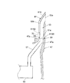
図13は第1実施形態に備えられるテールパイプと排気管の配置関係を示す要部断面図である。
上述した旋回体2の旋回フレーム2a上には、図示しないエンジンの排気ガスが導かれて消音するマフラ10と、このマフラ10から排出された排気ガスを導くテールパイプ11とが配置されている。例えばカウンタウェイト7には、上述した図12に示すこのカウンタウェイト7の穴7cに連通する通路7aを形成してある。テールパイプ11は、通路7a内に、この通路7aを形成するカウンタウェイト7の壁面と接触しないように挿入され、その上端11aが排気管13の内部に挿入されるように構成してある。
このように構成した第1実施形態は、エンジンの排気ガスがマフラ10、テールパイプ11を介して排気管13に導かれ、この排気管13の排気口13aからカウンタウェイト7の上方位置で外部に放出される。
また、この第1実施形態によれば、図4,5に示すように、運転席3に座ったオペレータ22が後方を目で確認しようとするとき、運転席3の座席基準点17と、運転席3の後側に立設する後側左支柱5dとを結ぶ仮想的な直線18上に位置する当該後側左支柱5dの背後に排気管13が完全に、あるいは略完全に隠れた状態になる。したがって、運転席3に座ったオペレータ22は後側左支柱5dによって視界を遮られるものの、排気管13によって視界を遮られることは少なくなり、当該ミニショベルで実施される作業の作業性を向上させることができる。また、この第1実施形態は、良好な後方視界を確保できることから、当該ミニショベルの後方に存在する構造物や人に対する安全性を確保することができる。
また、この第1実施形態によれば、排気ガスが導かれることによって排気管13が熱くなるが、この排気管13の表面からの輻射熱が運転席3の背後に立設された後側左支柱5dによって遮られる。これにより、運転席3に着座したオペレータ22に対して、排気ガスの熱による不快な暖かさを与えないようにすることができる。したがって、排気ガスの温度が高温となりやすい上述した排気ガス処理装置を備えた作業機械にあっては、排気管13の表面温度も高くなりやすい。このように排気管13の表面温度が高くなり、上述した輻射熱が高くなるミニショベルとしてもこの第1実施形態は好適である。
また、この第1実施形態によれば、排気管カバー21に含まれる第1,第2分割カバー部21A,21Bの下端部分に、ブラシ等の清掃具の挿入を許容させる開口部30を形成する第1,第2切り欠き部21A2,21B2を形成したことから、排気管13と第1,第2分割カバー部21A,21Bの隙間13bから枯葉等のゴミが侵入し、排気管13及び第1,第2分割カバー部21A,21Bの下端部付近に溜まった場合には、第1,第2分割カバー部21A,21Bを分解することなく、第1,第2分割カバー部21A,21Bの下端部分に形成した第1,第2切り欠き部21A2,21B2によって形成される開口部30にブラシ等の清掃具を挿入して、そのゴミを簡単に清掃除去することができる。これにより、第1,第2分割カバー部21A,21Bの下端部分に溜まったゴミの清掃作業を能率良く行うことができる。したがって、この第1実施形態は、上述したように排気ガス処理装置を備え排気ガスの温度が高くなりやすく、枯葉等のゴミの排気管13への接触を防ぐことが特に要望されるミニショベルとしても好適である。さらに、この第1実施形態は、町中等のように枯葉等のゴミが生じやすい作業環境で活用されることの多いミニショベルに好適である。
また、この第1実施形態によれば、第1,第2分割カバー部21A,21Bの第1,第2切り欠き部21A2,21B2によって形成される開口部30が運転席3の側のみに位置するように、第1,第2分割カバー部21A,21Bを配置してあることから、開口部30が運転席3の側に隠れた状態となり、これにより熱せられた排気管13への接触を防ぐことができる。また、この第1実施形態は、排気管13及び第1,第2分割カバー部21A,21Bの近傍であって運転席3側に形成され、開口部30に連通する隙間部分、すなわち運転席3と第1,第2分割カバー部21A,21Bとの間に形成される隙間部分にゴミが侵入した場合でも、その隙間部分のゴミを開口部30に溜まっているゴミと一緒に、ブラシ等の清掃具によって清掃除去することができる。
また、この第1実施形態によれば、第1分割カバー部21Aと第2分割カバー部21Bとの間に形成された隙間21Cから、排気ガスによる排気管13の熱を放散させることができるので、排気管13と第1,第2分割カバー部21A,21Bとの間に排気管13の熱がこもって、第1,第2分割カバー部21A,21Bが加熱することを防止できる。なお、第1,第2分割カバー部21A,21Bの隙間21Cから侵入し、排気管13及び第1,第2分割カバー部21A,21Bの下端部付近に溜まった枯葉等のゴミも、開口部30にブラシ等の清掃具を挿入することにより簡単に清掃除去することができる。
また、カウンタウェイト7の上面7bに第1,第2取り付け部21A3,21B3を取り付けることにより、第1分割カバー部21Aと第2分割カバー部21Bとを含む排気管カバー21を安定して立設保持させることができる。
また、この第1実施形態にあっては、排気管13の周面に固定した支持部材24b,24cと、これらの支持部材24b,24cによって支持される環状部材24aと、この環状部材24aに固定した立設部材24d,24eと、これらの立設部材24d,24eに第1,第2分割カバー部21A,21Bを取り付ける取り付け部材24f,24g及びボルト25とによって、第1,第2分割カバー部21A,21Bを安定に保持させることができる。
この第1実施形態にあっては、排気ガスに熱せられた排気管13の熱は、排気管13の周面に固定した支持部材24b,24cに伝えられ、これらの支持部材24b,24cから排気管13との間に隙間13bをもって配置した環状部材24aに伝えられ、さらにこの環状部材24aから当該環状部材24aに固定され、上下方向に延設させた立設部材24d,24eに取り付けられる第1,第2分割カバー部21A,21Bに伝えられる。したがって、排気管13から支持部材24b,24cに伝えられた熱は主に、支持部材24b,24cと立設部材24d,24eとの間に位置する環状部材24aの部分で冷やされた後、環状部材24aに取り付けられた立設部材24d,24eの部分と、第1,第2分割カバー部21A,21Bが取り付けられる取り付け部材24f,24g及びボルトが設けられる立設部材24d,24eの部分との間で冷やされて、立設部材24d,24eから取り付け部材24f,24g及びボルト25を介して、第1,第2分割カバー部21A,21Bへと伝えられる。
これらにより、この第1実施形態によれば、排気管13から第1,第2分割カバー部21A,21Bへ伝えられる熱を排気管13を囲むように配置される断熱材や、長尺体を形成する筒状部材を要することなく下げることができる。したがって、この第1実施形態に備えられる第1,第2分割カバー部21A,21Bに接触した際の安全性が確保される。また、この第1実施形態は、断熱材や、長尺体を形成する筒状部材を要さずに、排気管13との間に隙間13bをもって配置される環状部材24aを介して第1,第2分割カバー部21A,21Bを排気管13に保持させることができる。これにより、この第1実施形態は、構造の簡単な排気管カバー保持構造を実現させることができ、製作費を低減させることができる。
また、この第1実施形態は、排気管カバー21に含まれる第1分割カバー部21Aを、排気管13に固定した一対の支持部材24b,24cと、これらの支持部材24b,24cによって支持される環状部材24aと、この環状部材24aに固定した一対の立設部材24d,24eのうちの立設部材24dを介して排気管13に取り付けることができる。また、第2分割カバー部21Bを、排気管13に固定した一対の支持部材24b,24cと、これらの支持部材24b,24cによって支持される環状部材24aと、この環状部材24aに固定した立設部材24eを介して排気管13に取り付けることができる。また、一対の立設部材24d,24cのそれぞれは、曲げ加工されているので比較的大きな強度を確保することができる。これらにより、排気管カバー21に含まれる第1カバー部21Aと第2カバー部21Bとを排気管13に安定して立設保持させることができる。
また、この第1実施形態は、対向する第1分割カバー部21Aと第2分割カバー部21Bとの間に互いに隙間21Cを形成したことから、また、第1,第2分割カバー部21A,21Bの側面にスリット21A1等を形成したことから、排気管13の熱が第1分割カバー部21A及び第2分割カバー部21Bと、排気管13との間にこもらず、排気管13の熱を上述の隙間21C及びスリット21A等から外部に放散させることができる。したがって、このようなこもり熱による第1,第2分割カバー部21A,21Bの加熱を抑えることができる。
また、この第1実施形態は、一対の支持部材24b,24cを排気管13の上方部分に固定し、これらの支持部材24b,24cによって支持される環状部材24aに一対の立設部材24d,24eの下方部分を固定した構成にしてある。この構成により、カバー保持部24における排気管カバー21の取り付け位置を、排気管13の上部の高い位置とすることができる。ここで排気管13の下方部分は、マフラ10から排出される排気ガスの導入部付近に位置し、排気ガスの高い温度によりその下方部分の温度が高くなる。これに対して、排気管13の上方部分は、排気ガスの上昇に伴う温度低下により、この排気管13の上方部分の温度が下方部分に比べて低くなる。このように温度が低下した排気管13の上方部分の熱が支持部材24b,24c、環状部材24a、立設部材24d,24eを介して排気管カバー21に含まれる第1,第2分割カバー部21A,21Bに伝えられるので、カバー保持部24によって排気管13に取り付けられたこれらの第1,第2分割カバー部21A,21Bの温度を比較的低く抑えることができる。
また、この第1実施形態は、一対の支持部材24b,24cと一対の立設部材24d,24eを、平面視で互いに直交するように配置してある。平面視で一対の支持部材24d,24eの中央を通り、これらの支持部材24d,24eを左右に等分に分割する仮想的な中心線を考えた場合、第1分割カバー部21A側と第2分割カバー部21B側にそれぞれ位置する環状部材24aの部分、及び一対の立設部材24d,24eのそれぞれが、上述の中心線に対して対称に配置されるので、左右の安定した重量バランスを確保でき、これによって第1,第2分割カバー部21A,21Bの排気管13に対する安定保持を実現させることができる。また、支持部材24b,24cから環状部材24a、立設部材24d,24eを介して第1分割カバー部21A、あるいは第2分割カバー部21Bに伝えられる伝熱経路を比較的長い経路とすることができ、これによって第1,第2分割カバー部21A,21Bの温度を下げることに貢献する。
また、この第1実施形態によれば、第1,第2分割カバー部21A,21Bのそれぞれの上方部分がカバー保持部24によって保持され、下方部分がカウンタウェイト7に固定されるので、これらの第1,第2分割カバー部21A,21Bを、上述のように周囲の部材に接触しない自立した状態で安定に立設保持させることができる。したがって、第1,第2分割カバー部21A,21Bをこの第1,第2分割カバー部21A,21Bを取り巻く空気によって冷やすことができるとともに、第1,第2分割カバー部21A,21Bの熱が周囲の部材に伝えられることが防止される。また、部材数が多くなりがちなカバー保持部24を1つだけ備えたことから、製作費の節減に貢献する。
また、この第1実施形態は、排気管13の高さ寸法を、排気口13aがキャノピ4のルーフ6の最上部6aと最下部6bとの間に配置される高さ寸法に設定した構成にしてある。この構成に伴って、旋回体2の旋回時等には、排気管13の排気口13aから放出した排気ガスがキャノピ6の最上部6aと最下部6bとの間の部分によって遮られるので、運転席3方向への排気ガスの流れ込みを少なくすることができる。上述したような排気ガス処理装置を備えたミニショベルでは、排気管13の排気口13aから放出した排気ガスの温度が高くなるが、上述したように排気ガスの運転席3方向への流れ込みが少なくなることから、この点からもこの第1実施形態は、排気ガス処理装置を備えたミニショベルとしても特に好適である。
また、この第1実施形態は、キャノピ4のルーフ6から排気管13を突出させないようにすることができるので、トレーラに当該ミニショベルを乗せて運搬する際などに受ける高さ規制による制約を緩和させることができる。また、この第1実施形態は、建物内作業を実施するために建物の入口から進入しようとするときに、入口の高さがルーフ6の高さよりも高くなっている限りは、排気管13が入口の上部に当たることなく建物内に進入することができる。すなわち、この第1実施形態は、当該ミニショベルの運搬時や建物内作業時における制約を緩和させることができる。
また、この第1実施形態は、排気口13aが後方を向くように排気管13を配置してあるので、排気ガスの放出方向を運転席3とは逆の方向として、放出した排気ガスが運転席3方向へ流れ込まないようにすることができる。
また、この第1実施形態は、当該ミニショベルが設置される地面から排気管13の排気口13aまでの高さ寸法を大人の平均身長以上の高さ寸法に設定したことから、当該ミニショベルの周囲に存在する人に対する排気ガスからの保護を実現させることができる。
また、この第1実施形態は、図13に示すように、カウンタウェイト7にテールパイプ11が挿入される通路7aを設け、テールパイプ11の上端11aを排気管13に挿入させるようにしてあることから、マフラ10からテールパイプ11に導かれた排気ガスをカウンタウェイト7の通路7aを形成する壁面に放射させることがなく、また、テールパイプ11とカウンタウェイト7の通路を形成する壁面との間に隙間が設けられている。これらのことから、カウンタウェイト7が直接に加熱されることがなく、排気ガスによるカウンタウェイト7の昇温が低くなるように抑えることができる。したがって、排気管13から排気ガスを放出させる間、カウンタウェイト7への接触による不快感を生じさせないようにすることができる。
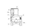
図14は本発明に係る作業機械の第2実施形態を構成するミニショベルの車体を示す側面図、図15は図14に示すミニショベルの車体の背面図、図16は図14に示すミニショベルの車体の平面図、図17は図14に示すミニショベルの車体から運転室の屋根を除いた状態を示す平面図、図18は図14に示すミニショベルの車体を斜め前方から見た斜視図である。
これらの図16~18に示すように、第2実施形態に係る作業機械も例えばミニショベルから成り、車体を構成する走行体41と、旋回体42とを備え、旋回体42の前側には図示しない作業装置が取り付けられる支持部56を備えている。作業装置は、ブーム、アーム、バケット等を備え、土砂の掘削作業等を実施することができる。
運転室44の後側に位置する旋回体2の部分には重量バランスを確保するカウンタウェイト47を設けてある。このカウンタウェイト47には、エンジンの排気ガスをカウンタウェイト47の上方で放出する排気口53aを有する後述の排気管53を運転室44から離した状態で立設保持させてある。また、後述の排気管53の周囲及び上部を囲むように配置され、排気管53への接触を防ぐ排気管カバー61を備えている。
この第2実施形態は、図17に示すように、運転席43のシップポイントである座席基準点57と、例えば運転室44に含まれる後側左支柱45とを結ぶ仮想的な直線58上に、後述の排気管53及び排気管カバー61を配置してある。これにより、運転席43にオペレータが着座した際には、排気管53及び排気管カバー61がオペレータの背後に位置する状態となっている。
図19は第2実施形態に備えられる排気管及び排気管カバーを示す図で、(a)図は正面図、(b)図は平面図、(c)図は正面側から見た斜視図、(d)図は背面側から見た斜視図、図20は第2実施形態に備えられる排気管及び排気管カバーを示す図で、(a)図は背面図、(b)図は(a)図のA-A断面図、(c)図は(a)図のB-B断面図、(d)図は(a)図のC-C断面図、(e)図は側面図である。
これらの図19,20に示すように、排気管53の下端には、排気管53の筒状部に連通する穴部を有し、カウンタウェイト47の上面に固定されるフランジ59を一体に設けてある。このフランジ59は、ボルト55によってカウンタウェイト47の上面に固定される。
この第2実施形態も、排気管カバー61の下端部分に、図示しないブラシ等の清掃具の挿入を許容させる開口部70を形成する切り欠き部を備えている。上述の開口部70が、図14に示すように、例えば運転席43が配置される運転室44側のみに位置するように排気管カバー61を配置してある。
排気管カバー61は、それぞれ排気管53の延設方向に沿うように延設され、排気管53を挟むように互いに隙間61Cをもって対向して配置される第1分割カバー部61Aと第2分割カバー部61Bとから成っている。上述した切り欠き部は、第1分割カバー部61Aの下端部分に形成される第1切り欠き部61A2と、第2分割カバー部61Bの下端部分に形成される第2切り欠き部61B2とから成っている。第1分割カバー部61Aと第2分割カバー部61Bは、それぞれの下端にカウンタウェイト47の上面に取り付けられる平板状の第1取付け部61A3、第2取り付け部61Bを備えている。これらの取り付け部61A3,61B3は、上述したボルト55によって排気管53のフランジ59と共締めされてカウンタウェイト47に固定されるようになっている。第1分割カバー部61Aの側面には、多数のスリット61A1を形成してある。同様に、第2分割カバー部61Bの側面にも多数のスリットを形成してある。
図19の(d)図及び図20の(a)図に示すように、第1分割カバー部61Aには連結具62が例えば一体に溶接されている。この連結具62と第2分割カバー部61Bとがボルト63によって締結されている。
図21は第2実施形態に備えられるテールパイプと排気管の配置関係を示す要部平面図である。
この第2実施形態も第1実施形態と同様に、旋回体42の旋回フレーム42aの上には、図示しないエンジンの排気ガスが導かれて消音するマフラ50と、このマフラ50から排出された排気ガスを導くテールパイプ51とが配置されている。カウンタウェイト47には、通路47aを形成してある。テールパイプ51は、通路47a内に、この通路47aを形成するカウンタウェイト47の壁面と接触しないように挿入され、その上端51aが排気管53の内部に挿入されるように構成してある。エンジンの排気ガスがマフラ50、テールパイプ51を介して排気管53の排気口53aから放出される点は第1実施形態と同じである。
この第2実施形態も第1実施形態と同様に、運転室44内の運転席43に座ったオペレータが後方を目で確認しようとするとき、運転席43の座席基準点57と、運転席43の後側に立設する後側左支柱45とを結ぶ仮想的な直線58上に位置する当該後側左支柱45の背後に排気管53が完全に、あるいは略完全に隠れた状態になる。したがって、運転席43に座ったオペレータが排気管53によって視界を遮られることが少なくなり、良好な後方視界を確保することができる。これにより、第1実施形態と同等の作用効果が得られる。また、この第2実施形態も排気ガス処理装置を備え、排気管53の輻射熱が高くなりやすいミニショベルにも好適である。
また、この第2実施形態も、排気管カバー61に含まれる第1,第2分割カバー部61A,61Bの下端部分に、ブラシ等の清掃具の挿入を許容させる開口部70を形成する第1,第2切り欠き部61A2,61B2を形成したことから、排気管53と第1,第2分割カバー部61A,61Bの隙間53bから枯葉等のゴミが侵入し、排気管53及び第1,第2分割カバー部61A,61Bの下端部付近に溜まった場合には、第1,第2分割カバー部61A,61Bを分解することなく、第1実施形態と同様に開口部70にブラシ等の清掃具を挿入して、そのゴミを簡単に清掃除去することができ、第1実施形態と同等の作用効果が得られる。
その他、第1実施形態と同等の構成部分を設けたことによる作用効果は、第1実施形態と同等である。
なお、上記第1実施形態は、運転席3の座席基準点17とキャノピ4の後側左支柱5dとを結ぶ仮想的な直線18の近傍位置に排気管13及び排気管カバー21を配置したが、直線18上に排気管13及び排気管カバー21を配置した構成にしてもよい。また、上記第2実施形態は、運転席43の座席基準点57と運転室44に含まれる後側左支柱45とを結ぶ仮想的な直線58上に排気管53及び排気管カバー61を配置したが、仮想的な直線58の近傍位置に排気管53及び排気管カバー61を配置した構成にしてもよい。
また、上記第1実施形態は、運転席3の座席基準点17とキャノピ4の後側左支柱5dとを結ぶ仮想的な直線18の近傍位置に排気管13及び排気管カバー21を配置したが、運転席3の座席基準点17とキャノピ4の後側右支柱5cとを結ぶ仮想的な直線上に、またはその仮想的な直線の近傍位置に、排気管13及び排気管カバー21を配置した構成にしてもよい。同様に、上記第2実施形態は、運転室44内の運転席43の座席基準点57と運転室44に含まれる後側左支柱45とを結ぶ仮想的な直線58上に排気管53及び排気管カバー61を配置したが、運転席43の座席基準点57と運転室44に含まれる後側右支柱とを結ぶ仮想的な直線上に、またはその仮想的な直線の近傍位置に、排気管53及び排気管カバー61を配置した構成にしてもよい。これらのように構成したものも、運転席3,43に着座したオペレータ等の良好な後方視界を確保することができる。
また、上記第1実施形態は、排気口13aが運転室3の後方を向くように排気管13を配置してあるが、排気口13aが側方を向くように排気管13を配置してもよい。第2実施形態も同様であり、排気口53aが運転室44の後方に向くように、あるいは運転室44の側方を向くように排気管53を配置するとよい。
また、上記第1実施形態は、排気管カバー21を排気管13に保持させるカバー保持部24を、排気管13の上方部分に1つだけ設けたが、排気管カバー21の下端部分をカウンタウェイト7に固定せず、排気管13の上方部分と、下方部分の双方に設けたカバー保持部24によって排気管カバー21を排気管13に保持させるように構成してもよい。
また、上記第1,第2実施形態に係る作業機械は、それぞれミニショベルから成っているが、本発明は、ミニショベルには限られない。本発明は、ミニショベルよりも大きな型式となる油圧ショベル等の作業機械にも適用可能である。
1 走行体(車体)
2 旋回体(車体)
3 運転席
4 キャノピ
5d 後側左支柱
6 ルーフ
6a 最上部
6a1 高さ位置
6b 最下部
6b1 高さ位置
7 カウンタウェイト
10 マフラ
11 テールパイプ
13 排気管
13a 排気口
13b 隙間
16 支持部
17 座席基準点
18 仮想的な直線
21 排気管カバー
21A 第1分割カバー部
21A2 第1切り欠き部
21B 第2分割カバー部
21B2 第2切り欠き部
21C 隙間
22 オペレータ
23 高さ領域
24 カバー保持部
24a 環状部材
24b 支持部材
24c 支持部材
24d 立設部材
24e 立設部材
24f 取り付け部材
24g 取り付け部材
25 ボルト
30 開口部
41 走行体(車体)
42 旋回体(車体)
43 運転席
44 運転室
45 後側左支柱
47 カウンタウェイト
50 マフラ
51 テールパイプ
53 排気管
53a 排気口
53b 隙間
56 支持部
57 座席基準点
58 仮想的な直線
61 排気管カバー
61A 第1分割カバー部
61A2 第1切り欠き部
61B 第2分割カバー部
61B2 第2切り欠き部
61C 隙間
70 開口部
2 旋回体(車体)
3 運転席
4 キャノピ
5d 後側左支柱
6 ルーフ
6a 最上部
6a1 高さ位置
6b 最下部
6b1 高さ位置
7 カウンタウェイト
10 マフラ
11 テールパイプ
13 排気管
13a 排気口
13b 隙間
16 支持部
17 座席基準点
18 仮想的な直線
21 排気管カバー
21A 第1分割カバー部
21A2 第1切り欠き部
21B 第2分割カバー部
21B2 第2切り欠き部
21C 隙間
22 オペレータ
23 高さ領域
24 カバー保持部
24a 環状部材
24b 支持部材
24c 支持部材
24d 立設部材
24e 立設部材
24f 取り付け部材
24g 取り付け部材
25 ボルト
30 開口部
41 走行体(車体)
42 旋回体(車体)
43 運転席
44 運転室
45 後側左支柱
47 カウンタウェイト
50 マフラ
51 テールパイプ
53 排気管
53a 排気口
53b 隙間
56 支持部
57 座席基準点
58 仮想的な直線
61 排気管カバー
61A 第1分割カバー部
61A2 第1切り欠き部
61B 第2分割カバー部
61B2 第2切り欠き部
61C 隙間
70 開口部
Claims (5)
- 旋回体と、この旋回体に取り付けた作業装置と、上記旋回体上に配置した運転席と、この運転席の後方に配置したカウンタウェイトと、上記旋回体上に配置され、エンジンの排気ガスが導かれるマフラと、このマフラから排出された排気ガスを上記カウンタウェイトの上方位置で放出させる排気口を有する排気管を備えた作業機械において、
上記運転席の後側に立設する複数の支柱を備え、
上記運転席の座席基準点と上記複数の支柱のうちのいずれかの支柱とを結ぶ仮想的な直線上、または上記仮想的な直線の近傍位置に、上記排気管を配置したことを特徴とする作業機械。 - 請求項1に記載の作業機械において、
当該作業機械がミニショベルから成り、
上記複数の支柱が、上記旋回体上に配置される運転室に含まれる支柱、または旋回体上に配置されるキャノピに含まれる支柱から成ることを特徴とする作業機械。 - 請求項2に記載の作業機械において、
上記排気管への接触を防ぐ排気管カバーを備え、上記排気管カバーの下端部分に、清掃具の挿入を許容させる開口部を形成する切り欠き部を設けたことを特徴とする作業機械。 - 請求項3に記載の作業機械において、
上記排気管カバーを上記排気管に保持させるカバー保持部を備え、
上記カバー保持部は、上記排気管の周面を囲むように上記排気管との間に隙間をもって配置した環状部材と、この環状部材を支持し上記排気管の周面に固定した支持部材と、上記環状部材に固定され、上下方向に延設させた立設部材と、この立設部材に上記排気管カバーを取り付ける取り付け手段とを備えたことを特徴とする作業機械。 - 請求項1項に記載の作業機械において、
上記作業機械が、上記旋回体上に配置され、上記運転席の上方を覆うルーフを有するキャノピを備えたミニショベルから成り、
上記排気管の高さ寸法を、上記排気口が上記キャノピの上記ルーフの最上部と最下部の間に配置される高さ寸法に設定したことを特徴とする作業機械。
Applications Claiming Priority (2)
| Application Number | Priority Date | Filing Date | Title |
|---|---|---|---|
| JP2012071930A JP5759407B2 (ja) | 2012-03-27 | 2012-03-27 | ミニショベル |
| JP2012-071930 | 2012-03-27 |
Publications (1)
| Publication Number | Publication Date |
|---|---|
| WO2013145384A1 true WO2013145384A1 (ja) | 2013-10-03 |
Family
ID=49258725
Family Applications (1)
| Application Number | Title | Priority Date | Filing Date |
|---|---|---|---|
| PCT/JP2012/075658 Ceased WO2013145384A1 (ja) | 2012-03-27 | 2012-10-03 | 作業機械 |
Country Status (2)
| Country | Link |
|---|---|
| JP (1) | JP5759407B2 (ja) |
| WO (1) | WO2013145384A1 (ja) |
Families Citing this family (2)
| Publication number | Priority date | Publication date | Assignee | Title |
|---|---|---|---|---|
| JP6052629B2 (ja) * | 2014-08-27 | 2016-12-27 | 井関農機株式会社 | 作業車輌の原動部構造 |
| JP6358704B2 (ja) * | 2014-10-29 | 2018-07-18 | 日立建機株式会社 | 搭乗式転圧ローラ車両 |
Citations (4)
| Publication number | Priority date | Publication date | Assignee | Title |
|---|---|---|---|---|
| JPH11256616A (ja) * | 1998-03-12 | 1999-09-21 | Yanmar Diesel Engine Co Ltd | 超小旋回型作業車 |
| JPH11256617A (ja) * | 1998-03-12 | 1999-09-21 | Yanmar Diesel Engine Co Ltd | 超小旋回型作業車 |
| JP2000073404A (ja) * | 1998-08-31 | 2000-03-07 | Yanmar Diesel Engine Co Ltd | 超小旋回作業機 |
| JP2005335475A (ja) * | 2004-05-25 | 2005-12-08 | Hitachi Constr Mach Co Ltd | 建設機械 |
-
2012
- 2012-03-27 JP JP2012071930A patent/JP5759407B2/ja active Active
- 2012-10-03 WO PCT/JP2012/075658 patent/WO2013145384A1/ja not_active Ceased
Patent Citations (4)
| Publication number | Priority date | Publication date | Assignee | Title |
|---|---|---|---|---|
| JPH11256616A (ja) * | 1998-03-12 | 1999-09-21 | Yanmar Diesel Engine Co Ltd | 超小旋回型作業車 |
| JPH11256617A (ja) * | 1998-03-12 | 1999-09-21 | Yanmar Diesel Engine Co Ltd | 超小旋回型作業車 |
| JP2000073404A (ja) * | 1998-08-31 | 2000-03-07 | Yanmar Diesel Engine Co Ltd | 超小旋回作業機 |
| JP2005335475A (ja) * | 2004-05-25 | 2005-12-08 | Hitachi Constr Mach Co Ltd | 建設機械 |
Also Published As
| Publication number | Publication date |
|---|---|
| JP5759407B2 (ja) | 2015-08-05 |
| JP2013204247A (ja) | 2013-10-07 |
Similar Documents
| Publication | Publication Date | Title |
|---|---|---|
| CN101253071B (zh) | 建筑机械的框架结构 | |
| CN103429826A (zh) | 驾驶室 | |
| CN104471153B (zh) | 推土机 | |
| CN102465543B (zh) | 工程机械的上框架 | |
| WO2013145384A1 (ja) | 作業機械 | |
| JP5842887B2 (ja) | 作業機械 | |
| JP6171561B2 (ja) | 作業機械 | |
| JP4156973B2 (ja) | 運転室補強構造 | |
| JP5731426B2 (ja) | 作業機械 | |
| JP4504283B2 (ja) | 建設機械 | |
| JP5759408B2 (ja) | ミニショベル | |
| JP2007063839A (ja) | 建設機械用保護構造物及び建設機械用キャブ | |
| JP5670943B2 (ja) | 作業機械 | |
| JP5883324B2 (ja) | 作業機械 | |
| JP2013204247A5 (ja) | ミニショベル | |
| JP2006007929A (ja) | キャブおよび作業機械 | |
| JP6411973B2 (ja) | 小型油圧ショベル | |
| JP4596982B2 (ja) | 建設機械のキャブ | |
| CN103827402A (zh) | 具有防火壁的工程机械 | |
| JP4214995B2 (ja) | 建設機械 | |
| JP5935326B2 (ja) | 建設機械 | |
| JP6268927B2 (ja) | 建設機械の排気構造 | |
| JP5953931B2 (ja) | 建設機械 | |
| JP2004330806A (ja) | 運転室保護構造 | |
| JP2014031618A (ja) | 作業機の保護枠 |
Legal Events
| Date | Code | Title | Description |
|---|---|---|---|
| 121 | Ep: the epo has been informed by wipo that ep was designated in this application |
Ref document number: 12873050 Country of ref document: EP Kind code of ref document: A1 |
|
| NENP | Non-entry into the national phase |
Ref country code: DE |
|
| 122 | Ep: pct application non-entry in european phase |
Ref document number: 12873050 Country of ref document: EP Kind code of ref document: A1 |