WO2013145342A1 - Rotor de roue et procédé de contrôle du rotor de roue - Google Patents
Rotor de roue et procédé de contrôle du rotor de roue Download PDFInfo
- Publication number
- WO2013145342A1 WO2013145342A1 PCT/JP2012/062352 JP2012062352W WO2013145342A1 WO 2013145342 A1 WO2013145342 A1 WO 2013145342A1 JP 2012062352 W JP2012062352 W JP 2012062352W WO 2013145342 A1 WO2013145342 A1 WO 2013145342A1
- Authority
- WO
- WIPO (PCT)
- Prior art keywords
- traction force
- force control
- level
- maximum
- wheel loader
- Prior art date
Links
Images


Classifications
-
- B—PERFORMING OPERATIONS; TRANSPORTING
- B60—VEHICLES IN GENERAL
- B60W—CONJOINT CONTROL OF VEHICLE SUB-UNITS OF DIFFERENT TYPE OR DIFFERENT FUNCTION; CONTROL SYSTEMS SPECIALLY ADAPTED FOR HYBRID VEHICLES; ROAD VEHICLE DRIVE CONTROL SYSTEMS FOR PURPOSES NOT RELATED TO THE CONTROL OF A PARTICULAR SUB-UNIT
- B60W30/00—Purposes of road vehicle drive control systems not related to the control of a particular sub-unit, e.g. of systems using conjoint control of vehicle sub-units, or advanced driver assistance systems for ensuring comfort, stability and safety or drive control systems for propelling or retarding the vehicle
- B60W30/18—Propelling the vehicle
- B60W30/18172—Preventing, or responsive to skidding of wheels
-
- E—FIXED CONSTRUCTIONS
- E02—HYDRAULIC ENGINEERING; FOUNDATIONS; SOIL SHIFTING
- E02F—DREDGING; SOIL-SHIFTING
- E02F9/00—Component parts of dredgers or soil-shifting machines, not restricted to one of the kinds covered by groups E02F3/00 - E02F7/00
- E02F9/20—Drives; Control devices
- E02F9/22—Hydraulic or pneumatic drives
- E02F9/2253—Controlling the travelling speed of vehicles, e.g. adjusting travelling speed according to implement loads, control of hydrostatic transmission
-
- E—FIXED CONSTRUCTIONS
- E02—HYDRAULIC ENGINEERING; FOUNDATIONS; SOIL SHIFTING
- E02F—DREDGING; SOIL-SHIFTING
- E02F9/00—Component parts of dredgers or soil-shifting machines, not restricted to one of the kinds covered by groups E02F3/00 - E02F7/00
- E02F9/20—Drives; Control devices
- E02F9/22—Hydraulic or pneumatic drives
- E02F9/2278—Hydraulic circuits
- E02F9/2289—Closed circuit
-
- E—FIXED CONSTRUCTIONS
- E02—HYDRAULIC ENGINEERING; FOUNDATIONS; SOIL SHIFTING
- E02F—DREDGING; SOIL-SHIFTING
- E02F9/00—Component parts of dredgers or soil-shifting machines, not restricted to one of the kinds covered by groups E02F3/00 - E02F7/00
- E02F9/20—Drives; Control devices
- E02F9/22—Hydraulic or pneumatic drives
- E02F9/2278—Hydraulic circuits
- E02F9/2292—Systems with two or more pumps
-
- E—FIXED CONSTRUCTIONS
- E02—HYDRAULIC ENGINEERING; FOUNDATIONS; SOIL SHIFTING
- E02F—DREDGING; SOIL-SHIFTING
- E02F9/00—Component parts of dredgers or soil-shifting machines, not restricted to one of the kinds covered by groups E02F3/00 - E02F7/00
- E02F9/20—Drives; Control devices
- E02F9/22—Hydraulic or pneumatic drives
- E02F9/2278—Hydraulic circuits
- E02F9/2296—Systems with a variable displacement pump
-
- F—MECHANICAL ENGINEERING; LIGHTING; HEATING; WEAPONS; BLASTING
- F16—ENGINEERING ELEMENTS AND UNITS; GENERAL MEASURES FOR PRODUCING AND MAINTAINING EFFECTIVE FUNCTIONING OF MACHINES OR INSTALLATIONS; THERMAL INSULATION IN GENERAL
- F16H—GEARING
- F16H61/00—Control functions within control units of change-speed- or reversing-gearings for conveying rotary motion ; Control of exclusively fluid gearing, friction gearing, gearings with endless flexible members or other particular types of gearing
- F16H61/38—Control of exclusively fluid gearing
- F16H61/40—Control of exclusively fluid gearing hydrostatic
- F16H61/42—Control of exclusively fluid gearing hydrostatic involving adjustment of a pump or motor with adjustable output or capacity
- F16H61/421—Motor capacity control by electro-hydraulic control means, e.g. using solenoid valves
-
- F—MECHANICAL ENGINEERING; LIGHTING; HEATING; WEAPONS; BLASTING
- F16—ENGINEERING ELEMENTS AND UNITS; GENERAL MEASURES FOR PRODUCING AND MAINTAINING EFFECTIVE FUNCTIONING OF MACHINES OR INSTALLATIONS; THERMAL INSULATION IN GENERAL
- F16H—GEARING
- F16H61/00—Control functions within control units of change-speed- or reversing-gearings for conveying rotary motion ; Control of exclusively fluid gearing, friction gearing, gearings with endless flexible members or other particular types of gearing
- F16H61/38—Control of exclusively fluid gearing
- F16H61/40—Control of exclusively fluid gearing hydrostatic
- F16H61/46—Automatic regulation in accordance with output requirements
- F16H61/472—Automatic regulation in accordance with output requirements for achieving a target output torque
-
- B—PERFORMING OPERATIONS; TRANSPORTING
- B60—VEHICLES IN GENERAL
- B60W—CONJOINT CONTROL OF VEHICLE SUB-UNITS OF DIFFERENT TYPE OR DIFFERENT FUNCTION; CONTROL SYSTEMS SPECIALLY ADAPTED FOR HYBRID VEHICLES; ROAD VEHICLE DRIVE CONTROL SYSTEMS FOR PURPOSES NOT RELATED TO THE CONTROL OF A PARTICULAR SUB-UNIT
- B60W2510/00—Input parameters relating to a particular sub-units
- B60W2510/30—Auxiliary equipments
- B60W2510/305—Power absorbed by auxiliaries
-
- B—PERFORMING OPERATIONS; TRANSPORTING
- B60—VEHICLES IN GENERAL
- B60W—CONJOINT CONTROL OF VEHICLE SUB-UNITS OF DIFFERENT TYPE OR DIFFERENT FUNCTION; CONTROL SYSTEMS SPECIALLY ADAPTED FOR HYBRID VEHICLES; ROAD VEHICLE DRIVE CONTROL SYSTEMS FOR PURPOSES NOT RELATED TO THE CONTROL OF A PARTICULAR SUB-UNIT
- B60W2540/00—Input parameters relating to occupants
- B60W2540/10—Accelerator pedal position
-
- B—PERFORMING OPERATIONS; TRANSPORTING
- B60—VEHICLES IN GENERAL
- B60W—CONJOINT CONTROL OF VEHICLE SUB-UNITS OF DIFFERENT TYPE OR DIFFERENT FUNCTION; CONTROL SYSTEMS SPECIALLY ADAPTED FOR HYBRID VEHICLES; ROAD VEHICLE DRIVE CONTROL SYSTEMS FOR PURPOSES NOT RELATED TO THE CONTROL OF A PARTICULAR SUB-UNIT
- B60W2710/00—Output or target parameters relating to a particular sub-units
- B60W2710/10—Change speed gearings
- B60W2710/105—Output torque
Definitions
- the present invention relates to a wheel loader and a method for controlling the wheel loader.
- Some wheel loaders are equipped with a so-called HST (Hydro Static Transmission).
- HST Hydro Static Transmission
- the HST type wheel loader drives a hydraulic pump by an engine, and drives a traveling hydraulic motor by hydraulic fluid discharged from the hydraulic pump. Thereby, the wheel loader travels.
- the vehicle speed and traction force can be controlled by controlling the engine speed, the capacity of the hydraulic pump, the capacity of the traveling hydraulic motor, and the like (see Patent Document 1).
- the operator can select execution of traction force control.
- the capacity of the traveling hydraulic motor is limited to an upper limit capacity smaller than the maximum capacity. Thereby, the maximum traction force is reduced.
- the operator selects execution of traction force control when a phenomenon such as slip or stall occurs due to excessive traction force. Thereby, the maximum traction force is reduced, and the occurrence of a phenomenon such as slip or stall is suppressed.
- Certain wheel loaders are configured so that the operator can select the maximum traction level for traction control.
- the operator preselects the maximum traction force level in the traction force control.
- the maximum traction force is limited to the selected level.
- the operator can select an appropriate level of traction force, for example, according to the road surface condition.
- the traction force required during excavation work is not constant, and the traction force required varies depending on the work situation. For this reason, it is not easy for the operator to select in advance what level of maximum traction force is optimal in order to prevent a phenomenon such as stall or slip from occurring. Therefore, in the wheel loader as described above, the operator must reselect the maximum traction force level every time the work situation changes during excavation work.
- the work performed by the wheel loader includes so-called lifting work.
- the hoisting operation is an operation of scooping up an object such as grass by excavation into a bucket and stacking it while moving forward.
- a large traction force is required.
- the traction force control is executed when the lifting work is performed, the work cannot be performed efficiently because the traction force is insufficient.
- the operator needs to perform an operation to change the maximum traction force during the traction force control to a larger level or an operation to cancel the traction force control. .
- Such an operation is cumbersome for the operator and becomes a factor of reducing the operability of the wheel loader.
- An object of the present invention is to provide a wheel loader and a wheel loader control method capable of obtaining a sufficient traction force at the time of lifting work and suppressing a decrease in operability.
- a wheel loader includes a work machine, an engine, a hydraulic pump, a traveling hydraulic motor, an accelerator operation member, a traction force control operation unit, a work situation determination unit, and an accelerator operation amount.
- a determination unit, a boom angle determination unit, and a traction force control unit are provided.
- the work machine has a boom and a bucket.
- the hydraulic pump is driven by the engine.
- the traveling hydraulic motor is driven by hydraulic oil discharged from the hydraulic pump.
- the accelerator operation member is operated to set a target engine speed.
- the tractive force control operation unit is operated to switch on / off tractive force control that reduces the maximum tractive force.
- the work situation determination unit determines whether or not the work situation is excavation.
- the accelerator operation amount determination unit determines whether or not the operation amount of the accelerator operation member is equal to or greater than a predetermined operation threshold.
- the boom angle determination unit determines whether the boom angle is equal to or greater than a predetermined angle threshold.
- the boom angle is an angle with respect to the horizontal direction of the boom.
- the traction force control unit reduces the maximum traction force more than the maximum traction force when the traction force control is off.
- the tractive force control unit increases the maximum tractive force when the determination condition is satisfied when the tractive force control is on.
- the determination conditions include that the work phase is excavation, the operation amount of the accelerator operation member is equal to or greater than a predetermined operation threshold, and the boom angle is equal to or greater than a predetermined angle threshold.
- the wheel loader according to the second aspect of the present invention is the wheel loader according to the first aspect, and the traction force control unit sets the control level of the traction force to a standard level in the traction force control.
- the maximum traction force at the standard level is smaller than the maximum traction force when the traction force control is off.
- the tractive force control unit changes the control level of the maximum tractive force to a high level when the tractive force control is on and the determination condition is satisfied.
- the high level maximum traction is greater than the standard level maximum traction.
- the wheel loader according to the third aspect of the present invention is the wheel loader according to the second aspect, and the high level maximum traction force is smaller than the maximum traction force when the traction force control is off.
- a wheel loader is the wheel loader according to the second aspect, wherein the traction force control operation unit includes a traction force level changing unit for changing the magnitude of the standard maximum traction force, and a standard A traction force control operation member for instructing execution of traction force control at a level.
- a wheel loader is the wheel loader according to the fourth aspect, wherein the high level maximum traction force is irrespective of the magnitude of the standard level maximum traction force changed by the traction force level changing unit. It is constant.
- the wheel loader according to a sixth aspect of the present invention is the wheel loader according to the fifth aspect, and when the traction force control is in the off state, the traction force is the maximum traction force when the vehicle speed is the first vehicle speed greater than zero. It becomes.
- the traction force at a high level when the vehicle speed is zero matches the traction force when the traction force control when the vehicle speed is zero is off.
- a wheel loader is the wheel loader according to the second aspect, wherein the traction force control unit sets the control level of the traction force when the traction force control is on and the determination condition is not satisfied. Return to standard level.
- a wheel loader is the wheel loader according to the first aspect, wherein the tractive force control operation section selects a tractive force control level from a plurality of levels and instructs execution of tractive force control. Traction force control selection unit.
- the tractive force control unit increases the maximum tractive force above the level selected by the tractive force control selection unit when the tractive force control is on and the determination condition is satisfied.
- a wheel loader is the wheel loader according to the eighth aspect, wherein the traction force control unit is selected by the traction force control selection unit when the traction force control is on and the determination condition is satisfied. Increase the maximum traction to a level one level higher than the given level.
- a wheel loader is the wheel loader according to the eighth aspect, wherein the traction force control unit sets a control level of the traction force when the traction force control is on and the determination condition is not satisfied. Return to the original level.
- the wheel loader according to the eleventh aspect of the present invention is the wheel loader according to the first aspect, and the traction force control unit does not increase the maximum traction force when the work phase is not excavation.
- a wheel loader is the wheel loader according to the first aspect, wherein the traction force control unit is configured to control the maximum traction force when the operation amount of the accelerator operation member is not equal to or greater than a predetermined operation threshold. Do not increase.
- a wheel loader is the wheel loader according to the first aspect, and the traction force control unit does not increase the maximum traction force when the boom angle is not equal to or greater than a predetermined angle threshold. .
- a wheel loader is the wheel loader according to the first aspect, and the work situation determination unit is configured to excavate the work situation based on the traveling state of the vehicle and the operating state of the work implement. It is determined whether or not there is.
- a wheel loader is the wheel loader according to the first aspect, wherein the tractive force control unit controls the displacement of the traveling hydraulic motor by controlling the tilt angle of the traveling hydraulic motor. Then, the maximum traction force is controlled by controlling the upper limit capacity of the traveling hydraulic motor.
- a wheel loader is the wheel loader according to any one of the first to fifteenth aspects, wherein the traction force ratio is a ratio of the maximum traction force to the maximum traction force when the traction force control is off.
- the control unit sets the traction force ratio in accordance with the operation amount of the accelerator operation member or the engine rotation speed while the traction force control is on.
- a wheel loader is the wheel loader according to the sixteenth aspect, wherein the traction force control unit sets the traction force ratio to a predetermined ratio when the traction force control is on and the determination condition is satisfied. Increase the control level of maximum tractive force by increasing.
- the control method according to the eighteenth aspect of the present invention is a wheel loader control method.
- the wheel loader includes a work machine, an engine, a hydraulic pump, a traveling hydraulic motor, an accelerator operation member, and a traction force control operation unit.
- the work machine has a boom and a bucket.
- the hydraulic pump is driven by the engine.
- the traveling hydraulic motor is driven by hydraulic oil discharged from the hydraulic pump.
- the accelerator operation member is operated to set a target engine speed.
- the tractive force control operation unit is operated to switch on / off tractive force control that reduces the maximum tractive force.
- the control method according to this aspect includes the following steps. In the first step, it is determined whether the work phase is excavation.
- the second step it is determined whether or not the boom angle is equal to or greater than a predetermined angle threshold.
- the third step it is determined whether or not the operation amount of the accelerator operation member is equal to or greater than a predetermined operation threshold.
- the boom angle is an angle with respect to the horizontal direction of the boom.
- the fourth step when the traction force control is on, the maximum traction force is reduced more than the maximum traction force when the traction force control is off.
- the maximum traction force is increased when the determination condition is satisfied when the traction force control is on.
- the determination conditions include that the work phase is excavation, the operation amount of the accelerator operation member is equal to or greater than a predetermined operation threshold, and the boom angle is equal to or greater than a predetermined angle threshold.
- the maximum traction force increases.
- the determination conditions include that the work phase is excavation, the operation amount of the accelerator operation member is equal to or greater than a predetermined operation threshold, and the boom angle is equal to or greater than a predetermined angle threshold. For this reason, that the determination condition is satisfied means that the wheel loader is performing the lifting work.
- the maximum traction force is automatically increased in such a state, so that a sufficient traction force can be obtained during the lifting work. Further, since it is not necessary for the operator to perform an operation for increasing the maximum traction force, it is possible to suppress a decrease in operability.
- the maximum traction force is reduced to the standard level maximum traction force by traction force control.
- the maximum traction force is automatically increased from the standard level maximum traction force to the high level maximum traction force.
- the high-level maximum traction force is smaller than the maximum traction force when the traction force control is in the off state. Accordingly, it is possible to prevent the maximum traction force from being excessively increased when the determination condition is satisfied.
- the size of the maximum traction force at the standard level can be changed by the traction force level change unit.
- the maximum traction force is automatically increased to a value larger than the standard level maximum traction force.
- the wheel loader can obtain a sufficient traction force during the lifting work.
- a large traction force can be obtained when the determination condition is satisfied.
- the maximum traction force returns to the standard level maximum traction force when the traction force control is on and the determination condition is not satisfied. Thereby, an appropriate maximum traction force according to the work situation can be obtained.
- the operator can select the control level of traction force from a plurality of levels and immediately execute it. Further, when the determination condition is satisfied, the maximum traction force increases from the level selected by the operator, so that the wheel loader can obtain a sufficient traction force during the lifting operation.
- the maximum traction force increases to a level one level higher than the level selected by the operator. That is, since the increased maximum traction force is a level that can be selected by the operator, the operator feels less uncomfortable with the operation. Thereby, the fall of operativity can be suppressed.
- the maximum traction force when the traction force control is on and the determination condition is not satisfied, the maximum traction force returns to the maximum traction force at the original level. Thereby, an appropriate maximum traction force according to the work situation can be obtained.
- the maximum traction force during standard traction force control when the work phase is not excavation, it is not necessary to increase the traction force, so the maximum traction force during standard traction force control is maintained.
- the maximum traction force when the maximum traction force is already increased from the maximum traction force during the standard traction force control, the maximum traction force may be returned to the maximum traction force during the standard traction force control.
- the maximum traction force during standard traction force control is maintained.
- the maximum traction force may be maintained as it is.
- the boom angle when the boom angle is not equal to or greater than the predetermined angle threshold value, it is not necessary to increase the traction force, so the maximum traction force during standard traction force control is maintained.
- the maximum traction force when the maximum traction force is already increased from the maximum traction force during the standard traction force control, the maximum traction force may be returned to the maximum traction force during the standard traction force control.
- the angle threshold value may have different values when the maximum traction force is increased and when it is decreased.
- the maximum traction force can be controlled by controlling the upper limit capacity of the traveling hydraulic motor.
- the maximum traction force when the traction force control is on is changed by the traction force control unit changing the traction force ratio.
- control level of the maximum traction force is increased by increasing the traction force ratio by a predetermined ratio.
- the maximum traction force increases when the traction force control is on and the determination condition is satisfied.
- the determination conditions include that the work phase is excavation, the operation amount of the accelerator operation member is equal to or greater than a predetermined operation threshold, and the boom angle is equal to or greater than a predetermined angle threshold. For this reason, that the determination condition is satisfied means that the wheel loader is performing the lifting work.
- the maximum traction force is automatically increased in such a state, so that a sufficient traction force can be obtained during the lifting work. Further, since it is not necessary for the operator to perform an operation for increasing the maximum traction force, it is possible to suppress a decrease in operability.
- the side view of the wheel loader concerning one embodiment of the present invention.
- the block diagram which shows the structure of the hydraulic drive mechanism mounted in the wheel loader.
- the figure which shows the output torque line of an engine.
- the figure which shows an example of a pump displacement-driving circuit pressure characteristic.
- the figure which shows an example of a motor capacity-driving circuit pressure characteristic.
- the figure which shows an example of the vehicle speed-traction force diagram of a wheel loader.
- the block diagram which shows the structure of a vehicle body controller. 6 is a flowchart showing a determination process for automatically increasing the maximum traction force during traction force control.
- the side view of the working machine for showing the definition of a boom angle.
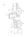
- FIG. 1 is a side view of the wheel loader 50.
- the wheel loader 50 includes a vehicle body 51, a work machine 52, a plurality of tires 55, and a cab 56.
- the work machine 52 is attached to the front portion of the vehicle body 51.
- the work machine 52 includes a boom 53, a bucket 54, a lift cylinder 19, and a bucket cylinder 26.
- the boom 53 is a member for lifting the bucket 54.
- the boom 53 is driven by the lift cylinder 19.
- the bucket 54 is attached to the tip of the boom 53.
- the bucket 54 is dumped and tilted by the bucket cylinder 26.
- the cab 56 is placed on the vehicle body 51.
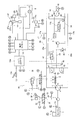
- FIG. 2 is a block diagram showing a configuration of the hydraulic drive mechanism 30 mounted on the wheel loader 50.
- the hydraulic drive mechanism 30 mainly includes an engine 1, a first hydraulic pump 4, a second hydraulic pump 2, a charge pump 3, a traveling hydraulic motor 10, an engine controller 12 a, a vehicle body controller 12, and a drive hydraulic circuit 20.
- the first hydraulic pump 4 is driven by the engine 1 to discharge hydraulic oil.
- the traveling hydraulic motor 10 is driven by the hydraulic oil discharged from the first hydraulic pump 4.
- the wheel loader 50 travels when the traveling hydraulic motor 10 rotationally drives the tire 55 described above. That is, the hydraulic drive mechanism 30 employs a so-called 1-pump 1-motor HST system.
- the engine 1 is a diesel engine, and output torque generated by the engine 1 is transmitted to the second hydraulic pump 2, the charge pump 3, the first hydraulic pump 4, and the like.
- the hydraulic drive mechanism 30 is provided with an engine rotation speed sensor 1 a that detects the actual rotation speed of the engine 1.
- the engine 1 is connected to a fuel injection device 1b.
- the engine controller 12a described later controls the output torque of the engine 1 (hereinafter referred to as “engine torque”) and the rotation speed by controlling the fuel injection device 1b.
- the first hydraulic pump 4 is driven by the engine 1 to discharge hydraulic oil.
- the first hydraulic pump 4 is a variable displacement hydraulic pump.
- the hydraulic oil discharged from the first hydraulic pump 4 is sent to the traveling hydraulic motor 10 through the drive hydraulic circuit 20.
- the drive hydraulic circuit 20 includes a first drive circuit 20a and a second drive circuit 20b.
- the traveling hydraulic motor 10 is driven in one direction (for example, forward direction).
- the traveling hydraulic motor 10 is driven in the other direction (for example, the reverse direction).
- the drive hydraulic circuit 20 is provided with a drive circuit pressure detector 17.
- the drive circuit pressure detector 17 detects the pressure of hydraulic oil (hereinafter referred to as “drive circuit pressure”) supplied to the traveling hydraulic motor 10 via the first drive circuit 20a or the second drive circuit 20b.
- the drive circuit pressure detection unit 17 includes a first drive circuit pressure sensor 17a and a second drive circuit pressure sensor 17b.
- the first drive circuit pressure sensor 17a detects the hydraulic pressure of the first drive circuit 20a.
- the second drive circuit pressure sensor 17b detects the hydraulic pressure of the second drive circuit 20b.
- the first drive circuit pressure sensor 17 a and the second drive circuit pressure sensor 17 b send detection signals to the vehicle body controller 12.
- the first hydraulic pump 4 is connected to an FR switching unit 5 and a pump capacity control cylinder 6 for controlling the discharge direction of the first hydraulic pump 4.
- the FR switching unit 5 is an electromagnetic control valve that switches the supply direction of hydraulic oil to the pump displacement control cylinder 6 based on a control signal from the vehicle body controller 12.
- the FR switching unit 5 switches the discharge direction of the first hydraulic pump 4 by switching the supply direction of the hydraulic oil to the pump displacement control cylinder 6.
- the FR switching unit 5 switches the discharge direction of the first hydraulic pump 4 between discharge to the first drive circuit 20a and discharge to the second drive circuit 20b.
- the pump displacement control cylinder 6 is driven by being supplied with hydraulic oil via the pump pilot circuit 32, and changes the tilt angle of the first hydraulic pump 4.
- the pump capacity control unit 7 is disposed in the pump pilot circuit 32.
- the pump displacement control unit 7 connects the pump displacement control cylinder 6 to either the pump pilot circuit 32 or the hydraulic oil tank.
- the pump displacement control unit 7 is an electromagnetic control valve that is controlled based on a control signal from the vehicle body controller 12.
- the pump displacement control unit 7 adjusts the tilt angle of the first hydraulic pump 4 by controlling the pressure of the hydraulic oil in the pump displacement control cylinder 6.
- the pump pilot circuit 32 is connected to the charge circuit 33 and the hydraulic oil tank via a cut-off valve 47.
- the pilot port of the cutoff valve 47 is connected to the first drive circuit 20a and the second drive circuit 20b via the shuttle valve 46.
- the shuttle valve 46 introduces the larger one of the hydraulic pressure of the first drive circuit 20 a and the hydraulic pressure of the second drive circuit 20 b to the pilot port of the cutoff valve 47. That is, the drive circuit pressure is applied to the pilot port of the cutoff valve 47.
- the cut-off valve 47 causes the charge circuit 33 and the pump pilot circuit 32 to communicate with each other when the drive circuit pressure is lower than a predetermined cut-off pressure. As a result, hydraulic oil is supplied from the charge circuit 33 to the pump pilot circuit 32.
- the cut-off valve 47 causes the pump pilot circuit 32 to communicate with the hydraulic oil tank and allows the hydraulic oil in the pump pilot circuit 32 to escape to the hydraulic oil tank. Thereby, when the hydraulic pressure of the pump pilot circuit 32 decreases, the capacity of the first hydraulic pump 4 is reduced, and an increase in the drive circuit pressure is suppressed.
- the charge pump 3 is a pump that is driven by the engine 1 and supplies hydraulic oil to the drive hydraulic circuit 20.
- the charge pump 3 is connected to the charge circuit 33.
- the charge pump 3 supplies hydraulic oil to the pump pilot circuit 32 via the charge circuit 33.
- the charge circuit 33 is connected to the first drive circuit 20a via the first check valve 41.
- the first check valve 41 allows the flow of hydraulic oil from the charge circuit 33 to the first drive circuit 20a, but restricts the flow of hydraulic oil from the first drive circuit 20a to the charge circuit 33.
- the charge circuit 33 is connected to the second drive circuit 20b via the second check valve 42.
- the second check valve 42 allows the flow of hydraulic oil from the charge circuit 33 to the second drive circuit 20b, but restricts the flow of hydraulic oil from the second drive circuit 20b to the charge circuit 33.
- the charge circuit 33 is connected to the first drive circuit 20a via the first relief valve 43.
- the first relief valve 43 is opened when the hydraulic pressure of the first drive circuit 20a becomes greater than a predetermined pressure.
- the charge circuit 33 is connected to the second drive circuit 20b via the second relief valve 44.
- the second relief valve 44 is opened when the hydraulic pressure of the second drive circuit 20b becomes greater than a predetermined pressure.
- the charge circuit 33 is connected to the hydraulic oil tank via the low pressure relief valve 45.
- the low pressure relief valve 45 is opened when the hydraulic pressure of the charge circuit 33 becomes higher than a predetermined relief pressure. Thereby, the drive circuit pressure is adjusted so as not to exceed a predetermined relief pressure.
- the predetermined relief pressure of the low pressure relief valve 45 is considerably lower than the relief pressure of the first relief valve 43 and the relief pressure of the second relief valve 44. Therefore, when the drive circuit pressure becomes lower than the hydraulic pressure of the charge circuit 33, hydraulic oil is supplied from the charge circuit 33 to the drive hydraulic circuit 20 via the first check valve 41 or the second check valve 42.
- the second hydraulic pump 2 is driven by the engine 1.
- the hydraulic oil discharged from the second hydraulic pump 2 is supplied to the lift cylinder 19 via the working machine hydraulic circuit 31.
- the discharge pressure of the second hydraulic pump 2 is detected by a discharge pressure sensor 39.
- the discharge pressure sensor 39 sends a detection signal to the vehicle body controller 12.
- the work machine hydraulic circuit 31 is provided with a work machine control valve 18.
- the work implement control valve 18 is driven according to the operation amount of the work implement operation member 23.
- the work machine control valve 18 controls the flow rate of the hydraulic oil supplied to the lift cylinder 19 according to the pilot pressure applied to the pilot port.
- the pilot pressure applied to the pilot port of the work implement control valve 18 is controlled by the pilot valve 23 a of the work implement operating member 23.
- the pilot valve 23 a applies a pilot pressure corresponding to the operation amount of the work implement operating member 23 to the pilot port of the work implement control valve 18.
- the pilot pressure applied to the pilot port of the work implement control valve 18 is detected by the PPC pressure sensor 21.
- the pressure of the hydraulic oil supplied to the lift cylinder 19 is detected by the boom pressure sensor 22.
- the PPC pressure sensor 21 and the boom pressure sensor 22 send detection signals to the vehicle body controller 12.
- the lift cylinder 19 is provided with a boom angle detector 38.
- the boom angle detection unit 38 detects a boom angle described later.
- the boom angle detection unit 38 is a sensor that detects the rotation angle of the boom 53.
- the boom angle detection unit 38 may detect the stroke amount of the lift cylinder 19 and calculate the rotation angle of the boom 53 from the stroke amount.
- the boom angle detection unit 38 sends a detection signal to the vehicle body controller 12.
- the bucket cylinder 26 is also controlled by a control valve in the same manner as the lift cylinder 19, but is not shown in FIG.
- the traveling hydraulic motor 10 is a variable displacement hydraulic motor.
- the traveling hydraulic motor 10 is driven by the hydraulic oil discharged from the first hydraulic pump 4 to generate a driving force for traveling.
- the traveling hydraulic motor 10 is provided with a motor cylinder 11a and a motor capacity controller 11b.
- the motor cylinder 11 a changes the tilt angle of the traveling hydraulic motor 10.
- the motor capacity control unit 11 b is an electromagnetic control valve that is controlled based on a control signal from the vehicle body controller 12.
- the motor capacity control unit 11 b controls the motor cylinder 11 a based on a control signal from the vehicle body controller 12.
- the motor cylinder 11 a and the motor capacity control unit 11 b are connected to a motor pilot circuit 34.
- the motor pilot circuit 34 is connected to the first drive circuit 20a via a check valve 48.
- the check valve 48 allows the flow of hydraulic oil from the first drive circuit 20a to the motor pilot circuit 34, but restricts the flow of hydraulic oil from the motor pilot circuit 34 to the first drive circuit 20a.
- the motor pilot circuit 34 is connected to the second drive circuit 20b via the check valve 49.
- the check valve 49 allows the flow of hydraulic oil from the second drive circuit 20b to the motor pilot circuit 34, but restricts the flow of hydraulic oil from the motor pilot circuit 34 to the second drive circuit 20b.
- the check valves 48 and 49 supply the larger hydraulic pressure of the first drive circuit 20 a and the second drive circuit 20 b, that is, hydraulic fluid having a drive circuit pressure, to the motor pilot circuit 34.
- the motor capacity control unit 11b switches the supply direction and supply flow rate of the hydraulic oil from the motor pilot circuit 34 to the motor cylinder 11a based on the control signal from the vehicle body controller 12.
- the vehicle body controller 12 can arbitrarily change the capacity of the traveling hydraulic motor 10.
- the upper limit capacity and the lower limit capacity of the traveling hydraulic motor 10 can be arbitrarily set.
- the hydraulic drive mechanism 30 is provided with a vehicle speed sensor 16.
- the vehicle speed sensor 16 detects the vehicle speed.
- the vehicle speed sensor 16 sends a detection signal to the vehicle body controller 12.
- the vehicle speed sensor 16 detects the vehicle speed, for example, by detecting the rotational speed of the tire drive shaft.
- the wheel loader 50 includes an accelerator operation member 13 a, a forward / reverse switching operation member 14, a traction force control operation unit 8, and an inching operation unit 27.
- the accelerator operation member 13a is a member for the operator to set the target rotation speed of the engine 1.
- the accelerator operation member 13a is an accelerator pedal, for example, and is operated by an operator.
- the accelerator operation member 13 a is connected to the accelerator operation amount sensor 13.
- the accelerator operation amount sensor 13 is composed of a potentiometer or the like.
- the accelerator operation amount sensor 13 sends a detection signal indicating the operation amount of the accelerator operation member 13a (hereinafter referred to as “accelerator operation amount”) to the engine controller 12a.
- the operator can control the rotational speed of the engine 1 by adjusting the accelerator operation amount.
- the forward / reverse switching operation member 14 is operated by an operator to be switched between a forward position, a reverse position, and a neutral position.
- the forward / reverse switching operation member 14 sends a detection signal indicating the position of the forward / reverse switching operation member 14 to the vehicle body controller 12.
- the operator can switch between forward and backward movement of the wheel loader 50 by operating the forward / reverse switching operation member 14.
- the traction force control operation unit 8 is operated by an operator and is operated to switch traction force control on and off.
- the traction force control is control for reducing the maximum traction force of the wheel loader 50.
- the maximum traction force is a peak value of traction force (see FIG. 6) that changes according to the vehicle speed.
- the tractive force control being in the off state means a state where the tractive force control is not being executed.
- the traction force control being in the on state means a state in which the traction force control is being executed.
- the traction force control operation unit 8 includes a traction force control operation member 15 and a setting operation device 24.
- the tractive force control operation member 15 is, for example, a switch.
- the traction force control operation member 15 is operated by an operator and is operated to instruct execution of traction force control described later. The traction force control will be described in detail later.
- the tractive force control operation member 15 sends a detection signal indicating the selected position of the tractive force control operation member 15 to the vehicle body controller 12.
- the setting operation device 24 is a device for performing various settings of the wheel loader 50.
- the setting operation device 24 is a display device with a touch panel function, for example.
- the setting operation device 24 includes a traction force level changing unit 24a.
- the control level of the traction force is set to a standard level.
- the maximum traction force at the standard level is smaller than the maximum traction force when the traction force control is off.
- the operator can change the magnitude of the maximum traction force at the standard level in the traction force control to a plurality of levels by operating the traction force level changing unit 24a.
- the inching operation unit 27 includes an inching operation member 27a and an inching operation sensor 27b.
- the inching operation member 27a is operated by an operator.
- the inching operation member 27a is a pedal, for example.
- the inching operation member 27a has both an inching operation function and a brake operation function.
- the inching operation sensor 27 b detects an operation amount of the inching operation member 27 a (hereinafter referred to as “inching operation amount”) and transmits a detection signal to the vehicle body controller 12.
- inching operation amount an operation amount of the inching operation member 27 a
- the vehicle body controller 12 reduces the hydraulic pressure of the pump pilot circuit 32 according to the operation amount of the inching operation member 27a. As a result, the drive circuit pressure decreases, and the rotational speed of the traveling hydraulic motor 10 decreases.
- the inching operation unit 27 is used, for example, when it is desired to increase the rotational speed of the engine 1 but suppress increase in traveling speed. That is, when the rotational speed of the engine 1 is increased by operating the accelerator operation member 13a, the hydraulic pressure of the pump pilot circuit 32 also increases. At this time, the increase in the hydraulic pressure of the pump pilot circuit 32 can be controlled by operating the inching operation member 27a.
- the inching operation member 27a is operated to reduce the vehicle speed without reducing the engine rotation speed.
- a brake valve 28 is connected to the inching operation member 27a.
- the brake valve 28 controls the supply of hydraulic oil to the hydraulic brake device 29.
- the inching operation member 27 a also serves as an operation member for the hydraulic brake device 29. Until the operation amount of the inching operation member 27a reaches a predetermined amount, only the inching operation described above is performed based on the detection signal from the inching operation sensor 27b. Then, when the operation amount of the inching operation member 27a reaches a predetermined amount, the operation of the brake valve 28 is started, whereby a braking force is generated in the hydraulic brake device 29.
- the braking force of the hydraulic brake device 29 is controlled according to the operation amount of the inching operation member 27a.
- the engine controller 12a is an electronic control unit having an arithmetic device such as a CPU and various memories.
- the engine controller 12a controls the engine 1 so that the set target rotational speed can be obtained.
- FIG. 3 shows an output torque line of the engine 1.
- the output torque line of the engine 1 shows the relationship between the rotational speed of the engine 1 and the maximum engine torque that can be output by the engine 1 at each rotational speed.
- a solid line L100 indicates an engine output torque line when the accelerator operation amount is 100%. This engine output torque line corresponds to, for example, the rating of the engine 1 or the maximum power output.
- the accelerator operation amount of 100% means that the accelerator operation member 13a is operated to the maximum.
- a broken line L75 indicates an engine output torque line when the accelerator operation amount is 75%.
- the engine controller 12a controls the output of the engine 1 so that the engine torque is equal to or less than the engine output torque line.
- the control of the output of the engine 1 is performed, for example, by controlling the upper limit value of the fuel injection amount
- the vehicle body controller 12 is an electronic control unit having an arithmetic device such as a CPU and various memories.
- the vehicle body controller 12 controls the capacity of the first hydraulic pump 4 and the capacity of the traveling hydraulic motor 10 by electronically controlling the control valves based on detection signals from the detection units.
- the vehicle body controller 12 outputs a command signal to the pump displacement control unit 7 based on the engine speed detected by the engine speed sensor 1a.
- FIG. 4 shows an example of pump capacity-drive circuit pressure characteristics.
- the pump capacity-drive circuit pressure characteristic indicates the relationship between the pump capacity and the drive circuit pressure.
- L11 to L16 in the figure are lines showing the pump displacement-drive circuit pressure characteristics that are changed according to the engine speed.
- the body displacement controller 12 controls the flow rate of the pump displacement control unit 7 based on the engine rotation speed, whereby the pump displacement / drive circuit pressure characteristic is changed to L11 to L16. Thereby, the pump capacity is controlled to a magnitude corresponding to the engine rotation speed and the drive circuit pressure.
- the vehicle body controller 12 processes detection signals from the engine rotation speed sensor 1a and the drive circuit pressure detection unit 17, and outputs a motor capacity command signal to the motor capacity control unit 11b.
- the vehicle body controller 12 sets the motor capacity from the value of the engine speed and the value of the drive circuit pressure with reference to the motor capacity-drive circuit pressure characteristics stored in the vehicle body controller 12.
- the vehicle body controller 12 outputs a tilt angle change command corresponding to the set motor capacity to the motor capacity controller 11b.
- FIG. 5 shows an example of motor capacity-drive circuit pressure characteristics.
- a solid line L21 in the figure is a line that defines the motor capacity with respect to the drive circuit pressure in a state where the engine speed is a certain value.
- the motor capacity here corresponds to the tilt angle of the traveling hydraulic motor 10.
- the tilt angle is minimum (Min). Thereafter, as the drive circuit pressure increases, the tilt angle gradually increases (inclined portion L22 indicated by a solid line). After the tilt angle reaches the maximum (Max), the tilt angle maintains the maximum tilt angle (Max) even if the drive circuit pressure increases.
- the inclined portion L22 defines the target pressure of the drive circuit pressure. That is, the vehicle body controller 12 increases the capacity of the traveling hydraulic motor when the drive circuit pressure becomes larger than the target pressure. Further, when the drive circuit pressure becomes smaller than the target pressure, the capacity of the traveling hydraulic motor is reduced. The target pressure is determined according to the engine speed. That is, the inclined portion L22 shown in FIG.
- the inclined portion L22 is controlled so that the tilt angle increases from a state where the drive circuit pressure is lower, and reaches the maximum tilt angle when the drive circuit pressure is lower. (Refer to the inclined portion L23 of the lower broken line in FIG. 5).
- the minimum tilt angle (Min) is maintained until the drive circuit pressure becomes higher, and the maximum tilt angle (Max) is reached with the drive circuit pressure being higher.
- the wheel loader 50 can change the traction force and the vehicle speed steplessly, and can automatically shift the vehicle speed from zero to the maximum speed without shifting operation.
- FIG. 6 the wheel loader 50 can change the traction force and the vehicle speed steplessly, and can automatically shift the vehicle speed from zero to the maximum speed without shifting operation.
- Lmax is a vehicle speed-traction force characteristic when the traction force control is in an off state.
- the traction force becomes the maximum traction force Tmax when the vehicle speed is the first vehicle speed V1 that is greater than zero.
- the traction force decreases as the vehicle speed decreases.
- the traction force decreases as the vehicle speed increases.
- the vehicle body controller 12 executes traction force control when the traction force control operation member 15 is operated.
- the vehicle body controller 12 changes the maximum traction force of the vehicle by changing the upper limit capacity of the traveling hydraulic motor 10. For example, as shown in FIG. 5, the vehicle body controller 12 outputs a command signal to the motor capacity control unit 11b so that the upper limit capacity is changed from Max to any one of Ma, Mb, and Mc.
- the vehicle speed-traction force characteristic changes as shown by a line La in FIG.
- the maximum traction force is reduced as compared with the line Lmax indicating the vehicle speed-traction force characteristic in a state where the traction force control is not performed.
- the maximum traction force of the vehicle is reduced to a preset standard level maximum traction force.
- the operator can select and set the magnitude of the maximum traction force at the standard level in traction force control in advance from a plurality of levels by operating the traction force level changing unit 24a described above.
- the tractive force level changing unit 24a can select a level set as a standard level from three levels of level A, level B, and level C.
- Level A is a level of traction force corresponding to the above-described upper limit capacity Ma.
- Level B is a level of traction force corresponding to the above-described upper limit capacity Mb.
- Level C is a level of traction force corresponding to the above-described upper limit capacity Mc.
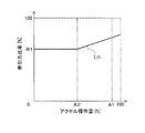
- FIG. 7 shows traction force ratio information that defines the relationship between the traction force ratio and the accelerator operation amount.
- the tractive force ratio indicates the ratio of the maximum tractive force in the tractive force control when the maximum tractive force is 100% when the tractive force control is in the off state.
- Ln is the traction force ratio information at the standard level.
- the tractive force ratio information Ln when the accelerator operation amount is equal to or less than a predetermined threshold A2, the tractive force ratio is constant at R1. When the accelerator operation amount is larger than the predetermined threshold A2, the tractive force ratio increases according to the accelerator operation amount.
- the vehicle body controller 12 controls the upper limit capacity of the traveling hydraulic motor 10 so that the maximum traction force as indicated by the traction force ratio information Ln is obtained when the traction force control level is set to the standard level in the automatic traction force control. .
- the traction force ratio in the traction force ratio information Ln is changed according to the selection result by the traction force level changing unit 24a.
- the vehicle body controller 12 changes the control level of the traction force from the standard level to the high level when a predetermined determination condition is satisfied during the traction force control.
- the control level of the traction force is changed by increasing or decreasing the traction force ratio described above by a predetermined ratio.
- Lup is a vehicle speed-traction force characteristic at a high level.
- the traction force when the vehicle speed is zero matches the traction force T0 when the vehicle speed is zero in the vehicle speed-traction force characteristic Lmax when the traction force control is in the off state. .
- the vehicle body controller 12 controls the upper limit capacity of the traveling hydraulic motor 10 so that the maximum traction force as indicated by the vehicle speed-traction force characteristic Lup is obtained when the determination condition is satisfied during the traction force control. As a result, the maximum traction force is automatically increased.
- a determination process for automatically increasing the maximum traction force in the traction force control will be described in detail.
- the vehicle body controller 12 includes a traction force control unit 61, a work situation determination unit 62, an accelerator operation determination unit 63, a boom angle determination unit 64, and a change flag determination unit 65.
- FIG. 9 is a flowchart illustrating a determination process for changing the control level of the traction force from the standard level to the high level during the traction force control.
- step S101 the tractive force control unit 61 sets the tractive force control level to the standard level.
- step S102 the tractive force control unit 61 sets the change flag to OFF.
- the change flag is set to ON when the traction force control level is raised from the standard level to the high level.
- the change flag is set to OFF when the tractive force control level is not increased from the standard level to the high level. That is, when the change flag is off, the tractive force control unit 61 maintains the tractive force control level at the standard level.
- the work situation determination section 62 determines whether or not the excavation flag is on.
- the work situation determination unit 62 determines whether the work situation is excavation based on the traveling state of the vehicle and the operating state of the work implement 52.
- the work situation determination unit 62 sets the excavation flag to ON when it is determined that the work situation is excavation.
- the work situation determination unit 62 sets the excavation flag to OFF. Specific work situation determination processing will be described later.
- the boom angle determination unit 64 determines whether or not the boom angle is equal to or greater than a predetermined angle threshold value B1.
- the boom angle determination unit 64 performs the above determination based on the detection signal from the boom angle detection unit 38.
- the boom angle is an angle ⁇ formed between a line connecting the boom pin 57 and the bucket pin 58 and the horizontal direction with the horizontal direction set to 0 degree in a side view.
- the angle below the horizontal direction is a negative value, and the angle above the horizontal direction is a positive value.
- the boom angle is defined to increase upward.
- the angle threshold B1 corresponds to a boom angle that can be taken during the lifting operation.
- the angle threshold B1 is ⁇ 20 degrees or more.
- the angle threshold B1 is, for example, ⁇ 10 degrees.
- step S105 the accelerator operation determination unit 63 determines whether or not the accelerator operation amount is equal to or greater than a predetermined accelerator threshold A1.
- the accelerator operation determination unit 63 performs the above determination based on the detection signal from the accelerator operation amount sensor 13.
- the accelerator threshold value A1 is a value large enough that the accelerator operation member 13a can be regarded as being operated to the maximum extent.
- the accelerator threshold A1 is larger than the above-described threshold A2 (see FIG. 7).
- the accelerator threshold A1 is preferably 80% or more. More preferably, the accelerator threshold A1 is 90% or more.
- step S106 the tractive force control unit 61 sets the tractive force control level to the standard level. That is, when either one of the conditions of Step S103 and Step S104 is not satisfied in a state where the control level of the traction force is the standard level, the control level of the traction force is maintained at the standard level. When either one of the conditions of step S103 and step S104 is not satisfied in a state where the control level of the traction force is high, the control level of traction force is returned from the high level to the standard level. Accordingly, the tractive force control unit 61 does not increase the maximum tractive force when the work phase is not excavation.
- the tractive force control unit 61 does not increase the maximum tractive force when the boom angle is not equal to or greater than the predetermined angle threshold value B1.
- the angle threshold may be set to B1 when the control level is raised from the standard level to the high level, and to B2 smaller than B1 when the control level is lowered from the high level to the standard level.
- step S105 If the condition in step S105 is not satisfied, the current control level is maintained. That is, the traction force control unit 61 does not increase the maximum traction force when the operation amount of the accelerator operation member 13a is not equal to or greater than the predetermined operation threshold A1. This is because the operability is impaired when the traction force changes according to the accelerator operation amount during the lifting work.
- step S107 the change flag determination unit 65 determines whether or not the change flag is off. That is, the change flag determination unit 65 determines whether or not the traction force control level is a standard level. If the change flag is off, that is, if the control level of the traction force is the standard level, the process proceeds to step S108.
- step S108 the tractive force control unit 61 sets the change flag to ON.
- step S109 the tractive force control unit 61 changes the tractive force control level from the standard level to the high level.
- the traction force control unit 61 controls the traction force based on the vehicle speed-traction force characteristic Lup shown in FIG.
- the high level maximum traction force is smaller than the maximum traction force when the traction force control is OFF.
- the above-described determination condition is applicable regardless of which level A (see La in FIG. 6), level B (see Lb in FIG. 6), or level C (see Lc in FIG. 6) is selected as the standard level.
- the traction force control unit 61 controls the traction force based on the vehicle speed-traction force characteristic Lup shown in FIG. That is, the high level maximum traction force is constant regardless of the magnitude of the standard level maximum traction force changed by the traction force level changing unit 24a. Specifically, the tractive force ratio corresponding to the high level is constant regardless of the magnitude of the standard tractive force ratio changed by the tractive force level changing unit 24a.
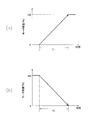
- the tractive force control unit 61 changes the tractive force at the same speed when the tractive force control level is raised from the standard level to the high level and when it is returned from the high level to the standard level. That is, the traction force control unit 61 changes the traction force at the same speed when increasing the maximum traction force and when reducing the maximum traction force in the traction force control.
- FIG. 11A shows the change speed of the command value of the motor capacity when the motor capacity is increased. That is, FIG. 11A shows the change speed of the command value of the motor capacity when the maximum traction force is increased.
- FIG. 11B shows the change speed of the command value of the motor capacity when the motor capacity is decreased. That is, FIG.
- 11B shows the change speed of the command value of the motor capacity when the maximum traction force is reduced.
- time T1 time T2. Therefore, the tractive force control unit 61 changes the command value of the motor capacity at the same speed when increasing the maximum tractive force and when decreasing the maximum tractive force.
- the time T1 and the time T2 are not limited to the same value, and may be different from each other.
- the time T1 when the maximum traction force is increased may be set to a value larger than the time T2 when the maximum traction force is decreased. In this case, it is possible to secure a sufficient traction force during the hoisting operation while suppressing the slip.
- step S107 shown in FIG. 9 when the change flag is not off, the control level of the traction force is maintained at a high level, and the determination from step S103 to step S107 is repeated.
- the control level of the traction force is returned from the high level to the standard level in step S106.
- FIG. 12 is a flowchart showing processing for determining whether or not the excavation flag is on. That is, FIG. 12 is a flowchart showing a process for determining whether or not the work phase is excavation.
- the work situation determination section 62 sets the excavation flag to off.
- the work situation determination section 62 determines whether or not the boom pressure reduction flag is on.
- the boom pressure reduction flag being on means that the bucket is in an empty state. The boom pressure reduction flag determination process will be described later.
- step S203 it is determined whether or not the boom angle is smaller than a predetermined angle threshold B2.
- the angle threshold B2 corresponds to a boom angle when the bucket is placed on the ground.
- the angle threshold B2 is smaller than the angle threshold B1 described above.
- the work situation determination section 62 determines whether or not the boom pressure is equal to or higher than the first boom pressure determination value.
- the boom pressure is a hydraulic pressure supplied to the lift cylinder 19 when the lift cylinder 19 is extended.
- the boom pressure is detected by the boom pressure sensor 22 described above.
- the first boom pressure determination value is a boom pressure value that can be taken during excavation.
- the first boom pressure determination value is obtained and set in advance by experiment or simulation.
- the first boom pressure determination value is a value corresponding to the boom angle.
- the vehicle body controller 12 stores boom pressure determination value information (hereinafter referred to as “first boom pressure determination value information”) indicating the relationship between the first boom pressure determination value and the boom angle.
- the first boom pressure determination value information is, for example, a table or map showing the relationship between the first boom pressure determination value and the boom angle.
- the work situation determination section 62 determines the first boom pressure determination value according to the boom angle by referring to the first boom pressure determination value information.
- step S205 the work situation determination section 62 sets the excavation flag to ON. That is, the work situation determination unit 62 determines that the work situation is excavation when all the conditions from step S202 to step S204 are satisfied. This is because when all the conditions from step S202 to step S204 are satisfied, it can be considered that the wheel loader 50 has entered the preparatory stage for excavation. When at least one of the conditions of steps S202, S203, and S204 is not satisfied, the determinations from step S202 to step S204 are repeated.
- step S206 the work situation determination section 62 sets the boom pressure reduction flag to OFF.
- step S207 the work situation determination section 62 determines whether or not the FNR recognition value is F.
- the FNR recognition value is information indicating whether the vehicle is in a forward drive state, a reverse drive state, or a neutral state.
- An FNR recognition value of F means that the vehicle is in a forward traveling state.
- An FNR recognition value of R means that the vehicle is in a reverse drive state.
- An FNR recognition value of N means that the vehicle is in a neutral state.
- the work situation determination unit 62 determines whether or not the FNR recognition value is F based on the detection signal from the forward / reverse switching operation member 14. When the FNR recognition value is not F, the process proceeds to step S209.
- step S209 the work situation determination section 62 sets the excavation flag to OFF. That is, the excavation flag is set to OFF when the vehicle is in a reverse state or a neutral state.
- step S207 when the FNR recognition value is F, the process proceeds to step S208.
- step S208 the work situation determination section 62 determines whether or not the boom pressure reduction flag is on.
- the process proceeds to step S209.
- the boom pressure reduction flag is not on, the process returns to step S207. Therefore, once it is determined that the work phase is excavation, the forward / reverse switching operation member 14 is thereafter switched from the forward movement position to the reverse movement position, or the forward / backward switching operation member 14 is changed from the forward movement position to the neutral position. Until switching, the excavation flag is kept on even if the conditions from step S202 to step S204 are not satisfied. Even if the forward / reverse switching operation member 14 is maintained at the forward position, the excavation flag is changed to off when the boom pressure reduction flag is set to on.
- FIG. 13 is a flowchart showing a process for determining whether or not the boom pressure reduction flag is ON. As shown in FIG. 13, in step S301, the work situation determination section 62 sets the boom pressure reduction flag to OFF.
- step S302 the work situation determination section 62 starts measuring the first timer.
- the first timer measures the duration for which the condition for setting the boom pressure reduction flag to ON is satisfied.
- the work situation determination section 62 determines whether or not the boom pressure is smaller than the second boom pressure determination value.
- the second boom pressure determination value is a boom pressure value that can be taken when the bucket is in an empty state.
- the vehicle body controller 12 stores boom pressure determination value information (hereinafter referred to as “second boom pressure determination value information”) indicating the relationship between the second boom pressure determination value and the boom angle.
- the second boom pressure determination value information is, for example, a table or map showing the relationship between the second boom pressure determination value and the boom angle.
- the work situation determination unit 62 determines the second boom pressure determination value according to the boom angle by referring to the second boom pressure determination value information.
- the second boom pressure determination value information when the boom angle is greater than 0 degrees, the second boom pressure determination value is constant at a value when the boom angle is 0 degrees.
- the second boom pressure determination value when the boom pressure increase rate when the boom angle is greater than 0 degrees is smaller than the boom pressure increase rate when the boom angle is less than 0 degrees and the boom angle is greater than 0 degrees. This is because the second boom pressure determination value when the boom angle is 0 degrees can be approximated.
- step S304 the work situation determination section 62 determines whether or not the time measured by the first timer is equal to or greater than a predetermined time threshold D2. That is, the duration determination unit 67 determines whether or not the duration of the state in which the condition of step S303 is satisfied is equal to or greater than the predetermined time threshold D2.
- the time threshold D2 is set to such a time that it can be considered that the condition of step S303 is not temporarily satisfied.
- the time threshold value D2 is larger than the time threshold value D1 described above.
- step S305 the work situation determination section 62 sets the boom pressure reduction flag to ON.
- step S306 the work situation determination section 62 ends the measurement of the first timer.
- step S303 when the boom pressure is not smaller than the second boom pressure determination value, the process proceeds to step S307.
- step S307 the work situation determination section 62 resets the first timer.
- step S308 the work situation determination section 62 starts measuring the second timer.
- step S309 the work situation determination section 62 determines whether or not the excavation flag is on. When the excavation flag is on, the process proceeds to step S310.
- step S310 the work situation determination section 62 ends the measurement of the second timer. And it returns to step S301 and the work situation determination part 62 sets a boom pressure fall flag to OFF.
- step S309 when the excavation flag is not on, the process proceeds to step S311.
- step S311 the work situation determination section 62 determines whether or not the boom pressure is smaller than the second boom pressure determination value. When the boom pressure is smaller than the second boom pressure determination value, the process proceeds to step S312.
- step S312 the work situation determination section 62 determines whether the time measured by the second timer is equal to or greater than a predetermined time threshold D3. When the measurement time by the second timer is equal to or greater than the predetermined time threshold D3, the process proceeds to step S310. Similarly to the above, in step S310, the work situation determination section 62 ends the measurement of the second timer, and in step S301, sets the boom pressure reduction flag to OFF. In step S312, when the time measured by the second timer is not equal to or greater than the predetermined time threshold D3, the process returns to step S309.
- step S311 when the boom pressure is not smaller than the second boom pressure determination value, the process proceeds to step S313.
- step S313 the work situation determination section 62 resets the second timer and returns to step S309.
- the wheel loader 50 raises the control level of the traction force from the standard level to the high level when the above-described determination condition is satisfied during the traction force control. This increases the maximum traction force.
- the determination conditions include that the work phase is excavation, the operation amount of the accelerator operation member is equal to or greater than a predetermined operation threshold, and the boom angle is equal to or greater than a predetermined angle threshold. For this reason, that the determination condition is satisfied means that the wheel loader is performing the lifting work.
- the maximum traction force is automatically increased in such a state, so that a sufficient traction force can be obtained during the lifting operation. Further, since it is not necessary for the operator to perform an operation for increasing the maximum traction force, it is possible to suppress a decrease in operability.
- the tractive force control unit 61 increases the tractive force control level from the standard level to a high level, but the maximum tractive force at the high level is smaller than the maximum tractive force when the tractive force control is off. Accordingly, it is possible to prevent the maximum traction force from being excessively increased when the determination condition is satisfied.
- the operator can change the size of the maximum traction force at the standard level by operating the traction force level changing unit 24a.
- the tractive force control unit 61 increases the maximum tractive force to a value larger than the maximum tractive force at the standard level. Thereby, the operator can set the required maximum traction force more finely according to the work situation.
- the vehicle speed-traction force characteristic Lup in FIG. Will be changed to the level.
- the wheel loader can obtain a sufficient traction force during the lifting work.
- the change in the traction force with respect to the change in the vehicle speed is small compared to the vehicle speed-traction force characteristic Lmax when the traction force control is in the off state. Specifically, in FIG.
- the traction force control unit 61 When the determination condition is not satisfied during the traction force control, the traction force control unit 61 returns the traction force control level to the standard level. Specifically, when the work phase is no longer excavation during the traction force control, the traction force control unit 61 returns the control level of the traction force to the standard level. Further, when the boom angle becomes smaller than the predetermined angle threshold B1 during the traction force control, the traction force control unit 61 returns the control level of the traction force to the standard level. Thereby, an appropriate maximum traction force according to the work situation can be obtained.
- the traction force control level is maintained at the current level, so that the traction force frequently increases or decreases according to the change of the accelerator operation amount. Since this can be suppressed, a decrease in operability can be suppressed.
- the wheel loader 50 equipped with an HST system of one pump and one motor including one hydraulic pump and the traveling hydraulic motor 10 has been described as an example.
- the present invention is not limited to this.
- the present invention may be applied to a wheel loader equipped with a 1-pump 2-motor HST system including one first hydraulic pump and two traveling hydraulic motors.
- the traction force level changing unit 24a can change the magnitude of the maximum traction force at the standard level in three stages.
- the tractive force level changing unit 24a may be capable of changing the magnitude of the standard level maximum tractive force to a plurality of stages other than the three stages.
- the traction force level changing unit 24a may be capable of continuously changing the magnitude of the maximum traction force at the standard level to an arbitrary magnitude.
- the tractive force level changing unit 24a may be omitted. That is, the standard level maximum traction force may not be changeable.
- the determination condition is not limited to the above condition, and other conditions may be added. Alternatively, some of the determination conditions described above may be changed.
- the tractive force control unit 61 reduces the maximum tractive force by changing the upper limit capacity of the motor capacity, but may reduce the maximum tractive force by other methods.
- the traction force control unit 61 may reduce the maximum traction force by controlling the drive circuit pressure.
- the drive circuit pressure is controlled, for example, by controlling the capacity of the first hydraulic pump 4.
- the traction force ratio information is set so that the traction force ratio increases as the accelerator operation amount increases, but the traction force ratio information is set so that the traction force ratio is constant regardless of the accelerator operation amount. It may be set.
- the traction force control level is set to a preset level by operating the traction force control operation member 15.
- the operator directly sets the traction force control level from a plurality of levels.
- the tractive force control operation unit 8 may be configured so that execution can be selected and instructed.
- the traction force control operation unit 8 includes a traction force control selection unit 24b.
- the tractive force control selection unit 24b is operated to instruct selection of a tractive force control level and execution of tractive force control.
- the operator selects the traction force control level from a plurality of levels by the traction force control selection unit 24b and instructs the execution of the traction force control.
- L1 indicates the vehicle speed-traction force characteristic at the first level.
- L2 indicates the vehicle speed-traction force characteristic at the second level.
- L3 indicates the vehicle speed-traction force characteristic at the third level.
- L4 indicates the vehicle speed-traction force characteristic at the fourth level.
- L5 indicates the vehicle speed-traction force characteristic at the fifth level.
- the maximum tractive force at the first level is the smallest and the maximum tractive force at the fifth level is the largest.
- the vehicle speed-traction force characteristic at the fifth level matches the above-described vehicle speed-traction force characteristic at the high level (see Lup in FIG. 6).
- the traction force control unit 61 increases the maximum traction force when the determination condition is satisfied during the traction force control. For example, the traction force control unit 61 increases the maximum traction force to a level one level higher than the level selected by the traction force control selection unit 24b when the determination condition is satisfied during the traction force control. Specifically, when the determination condition is satisfied during the traction force control at the first level, the traction force control unit 61 increases the control level to the second level.
- the traction force control unit 61 When the determination condition is satisfied during the traction force control at the second level, the traction force control unit 61 increases the control level to the third level. When the determination condition is satisfied during the traction force control at the third level, the traction force control unit 61 increases the control level to the fourth level. When the determination condition is satisfied during the traction force control at the fourth level, the traction force control unit 61 increases the control level to the fifth level. However, when the determination condition is satisfied during the traction force control at the fifth level, the traction force control unit 61 maintains the control level at the fifth level. When the determination condition is not satisfied during the traction force control, the traction force control unit 61 returns the control level of the traction force to the original level.
- the operator can select the control level of the traction force from a plurality of levels and operate it immediately by operating the traction force control selection unit 24b. Further, when the determination condition is satisfied, the maximum traction force increases from the level selected by the operator, so that the wheel loader can obtain a sufficient traction force during the lifting operation. Furthermore, since the increased maximum traction force is a level that can be selected by the operator, the operator feels less uncomfortable with the operation. Thereby, the fall of operativity can be suppressed.
- the number of levels selectable by the tractive force control selection unit 24b is not limited to five.
- the traction force control selection unit 24b may select less than five or more than five levels.
- the maximum traction force of an arbitrary magnitude may be continuously selectable by the traction force control selection unit 24b.
- the control level of the traction force may be increased to a level higher than two levels, not limited to the level one level higher than the current level.
- the control level of the traction force may be raised to a level other than the level selectable by the traction force control selection unit 24b.
- the traction force control operation unit 8 may include a traction force control selection unit 24b together with the traction force control operation member 24b and the traction force level change unit 24a described above. That is, the traction force control operation unit 8 may be configured such that the traction force control by the traction force control operation member 24b and the traction force level change unit 24a and the traction force control by the traction force control selection unit 24b are selectively executed.
- a wheel loader and a wheel loader control method capable of obtaining a sufficient traction force at the time of lifting work and suppressing a decrease in operability.
Abstract
Priority Applications (4)
| Application Number | Priority Date | Filing Date | Title |
|---|---|---|---|
| CN201280001364.0A CN103443512B (zh) | 2012-03-30 | 2012-05-15 | 轮式装载机及轮式装载机的控制方法 |
| EP12791681.5A EP2667060B1 (fr) | 2012-03-30 | 2012-05-15 | Chargeuse sur roues et méthode pour la contrôler |
| US13/700,405 US8649945B2 (en) | 2012-03-30 | 2012-05-15 | Wheel loader and wheel loader control method |
| JP2012524798A JP5092071B1 (ja) | 2012-03-30 | 2012-05-15 | ホイールローダ及びホイールローダの制御方法 |
Applications Claiming Priority (2)
| Application Number | Priority Date | Filing Date | Title |
|---|---|---|---|
| JP2012078938 | 2012-03-30 | ||
| JP2012-078938 | 2012-03-30 |
Publications (1)
| Publication Number | Publication Date |
|---|---|
| WO2013145342A1 true WO2013145342A1 (fr) | 2013-10-03 |
Family
ID=49258697
Family Applications (1)
| Application Number | Title | Priority Date | Filing Date |
|---|---|---|---|
| PCT/JP2012/062352 WO2013145342A1 (fr) | 2012-03-30 | 2012-05-15 | Rotor de roue et procédé de contrôle du rotor de roue |
Country Status (3)
| Country | Link |
|---|---|
| EP (1) | EP2667060B1 (fr) |
| CN (1) | CN103443512B (fr) |
| WO (1) | WO2013145342A1 (fr) |
Cited By (4)
| Publication number | Priority date | Publication date | Assignee | Title |
|---|---|---|---|---|
| WO2018062332A1 (fr) * | 2016-09-28 | 2018-04-05 | 株式会社Kcm | Véhicule de chantiervéhicule de chantier |
| WO2019065123A1 (fr) * | 2017-09-29 | 2019-04-04 | 株式会社Kcm | Chargeuse sur roues |
| WO2019064527A1 (fr) * | 2017-09-29 | 2019-04-04 | 株式会社Kcm | Chargeur à roues |
| WO2019065122A1 (fr) * | 2017-09-29 | 2019-04-04 | 株式会社Kcm | Chargeuse sur roues |
Families Citing this family (1)
| Publication number | Priority date | Publication date | Assignee | Title |
|---|---|---|---|---|
| CN104527628B (zh) * | 2014-12-30 | 2017-03-22 | 郑州宇通重工有限公司 | 一种轮胎式推土机微动功能和液压制动控制系统 |
Citations (4)
| Publication number | Priority date | Publication date | Assignee | Title |
|---|---|---|---|---|
| JPH07229560A (ja) * | 1994-02-18 | 1995-08-29 | Komatsu Ltd | 静油圧−機械式変速機の制御装置 |
| JP2004024172A (ja) * | 2002-06-27 | 2004-01-29 | Iseki & Co Ltd | ロータリの耕耘ピッチ制御装置 |
| JP2008144942A (ja) | 2006-12-13 | 2008-06-26 | Komatsu Ltd | 建設車両の牽引力制御装置 |
| JP2011063945A (ja) * | 2009-09-15 | 2011-03-31 | Kcm:Kk | 産業用車両 |
Family Cites Families (3)
| Publication number | Priority date | Publication date | Assignee | Title |
|---|---|---|---|---|
| JP5074086B2 (ja) * | 2007-04-26 | 2012-11-14 | 株式会社小松製作所 | 建設車両 |
| US7853389B2 (en) * | 2007-10-29 | 2010-12-14 | Ford Global Technologies, Llc | Traction control for performance and demonstration spin |
| JP5261419B2 (ja) * | 2010-03-05 | 2013-08-14 | 株式会社小松製作所 | 作業車両及び作業車両の制御方法 |
-
2012
- 2012-05-15 WO PCT/JP2012/062352 patent/WO2013145342A1/fr active Application Filing
- 2012-05-15 EP EP12791681.5A patent/EP2667060B1/fr active Active
- 2012-05-15 CN CN201280001364.0A patent/CN103443512B/zh active Active
Patent Citations (4)
| Publication number | Priority date | Publication date | Assignee | Title |
|---|---|---|---|---|
| JPH07229560A (ja) * | 1994-02-18 | 1995-08-29 | Komatsu Ltd | 静油圧−機械式変速機の制御装置 |
| JP2004024172A (ja) * | 2002-06-27 | 2004-01-29 | Iseki & Co Ltd | ロータリの耕耘ピッチ制御装置 |
| JP2008144942A (ja) | 2006-12-13 | 2008-06-26 | Komatsu Ltd | 建設車両の牽引力制御装置 |
| JP2011063945A (ja) * | 2009-09-15 | 2011-03-31 | Kcm:Kk | 産業用車両 |
Non-Patent Citations (1)
| Title |
|---|
| See also references of EP2667060A4 * |
Cited By (14)
| Publication number | Priority date | Publication date | Assignee | Title |
|---|---|---|---|---|
| WO2018062332A1 (fr) * | 2016-09-28 | 2018-04-05 | 株式会社Kcm | Véhicule de chantiervéhicule de chantier |
| CN109154152A (zh) * | 2016-09-28 | 2019-01-04 | 株式会社Kcm | 作业车辆 |
| CN109154152B (zh) * | 2016-09-28 | 2021-03-09 | 日立建机株式会社 | 作业车辆 |
| US10669696B2 (en) | 2016-09-28 | 2020-06-02 | Hitachi Construction Machinery Co., Ltd. | Work vehicle |
| JP2019065576A (ja) * | 2017-09-29 | 2019-04-25 | 株式会社Kcm | ホイールローダ |
| JP2019065574A (ja) * | 2017-09-29 | 2019-04-25 | 株式会社Kcm | ホイールローダ |
| WO2019065122A1 (fr) * | 2017-09-29 | 2019-04-04 | 株式会社Kcm | Chargeuse sur roues |
| WO2019064527A1 (fr) * | 2017-09-29 | 2019-04-04 | 株式会社Kcm | Chargeur à roues |
| WO2019065123A1 (fr) * | 2017-09-29 | 2019-04-04 | 株式会社Kcm | Chargeuse sur roues |
| US11242672B2 (en) | 2017-09-29 | 2022-02-08 | Hitachi Construction Machinery Co., Ltd. | Wheel loader |
| JP7038516B2 (ja) | 2017-09-29 | 2022-03-18 | 日立建機株式会社 | ホイールローダ |
| JP7038515B2 (ja) | 2017-09-29 | 2022-03-18 | 日立建機株式会社 | ホイールローダ |
| US11391017B2 (en) | 2017-09-29 | 2022-07-19 | Hitachi Construction Machinery Co., Ltd. | Wheel loader |
| US11505921B2 (en) | 2017-09-29 | 2022-11-22 | Hitachi Construction Machinery Co., Ltd. | Wheel loader |
Also Published As
| Publication number | Publication date |
|---|---|
| CN103443512A (zh) | 2013-12-11 |
| EP2667060A1 (fr) | 2013-11-27 |
| CN103443512B (zh) | 2014-09-24 |
| EP2667060A4 (fr) | 2014-04-02 |
| EP2667060B1 (fr) | 2014-12-10 |
Similar Documents
| Publication | Publication Date | Title |
|---|---|---|
| JP5092071B1 (ja) | ホイールローダ及びホイールローダの制御方法 | |
| JP5092070B1 (ja) | ホイールローダ及びホイールローダの制御方法 | |
| JP5161380B1 (ja) | 作業車両及び作業車両の制御方法 | |
| JP5192605B1 (ja) | ホイールローダ | |
| JP5192601B1 (ja) | 作業車両及び作業車両の制御方法 | |
| WO2013145340A1 (fr) | Rotor de roue et procédé de contrôle du rotor de roue | |
| JP5092060B1 (ja) | 作業車両及び作業車両の制御方法 | |
| JP5113946B1 (ja) | 作業車両及び作業車両の制御方法 | |
| JP5092061B1 (ja) | 作業車両及び作業車両の制御方法 | |
| EP3273110B1 (fr) | Chargeuse sur roues, et son procédé de commande | |
| JP5092069B1 (ja) | ホイールローダ及びホイールローダの制御方法 | |
| WO2013145342A1 (fr) | Rotor de roue et procédé de contrôle du rotor de roue | |
| JP5106694B1 (ja) | 作業車両及び作業車両の制御方法 | |
| JP6351678B2 (ja) | ホイールローダ及びその制御方法 |
Legal Events
| Date | Code | Title | Description |
|---|---|---|---|
| ENP | Entry into the national phase |
Ref document number: 2012524798 Country of ref document: JP Kind code of ref document: A |
|
| WWE | Wipo information: entry into national phase |
Ref document number: 13700405 Country of ref document: US |
|
| WWE | Wipo information: entry into national phase |
Ref document number: 2012791681 Country of ref document: EP |
|
| 121 | Ep: the epo has been informed by wipo that ep was designated in this application |
Ref document number: 12791681 Country of ref document: EP Kind code of ref document: A1 |
|
| NENP | Non-entry into the national phase |
Ref country code: DE |