WO2013145103A1 - ハイブリッド車両の駆動制御装置 - Google Patents
ハイブリッド車両の駆動制御装置 Download PDFInfo
- Publication number
- WO2013145103A1 WO2013145103A1 PCT/JP2012/057822 JP2012057822W WO2013145103A1 WO 2013145103 A1 WO2013145103 A1 WO 2013145103A1 JP 2012057822 W JP2012057822 W JP 2012057822W WO 2013145103 A1 WO2013145103 A1 WO 2013145103A1
- Authority
- WO
- WIPO (PCT)
- Prior art keywords
- electric motor
- rotating element
- torque
- engine
- differential mechanism
- Prior art date
Links
- 230000007246 mechanism Effects 0.000 claims abstract description 74
- 230000002159 abnormal effect Effects 0.000 claims abstract description 59
- 238000006243 chemical reaction Methods 0.000 claims description 47
- 230000001105 regulatory effect Effects 0.000 abstract 2
- 238000010586 diagram Methods 0.000 description 34
- 238000012937 correction Methods 0.000 description 18
- 239000000969 carrier Substances 0.000 description 9
- 239000000446 fuel Substances 0.000 description 7
- 230000006870 function Effects 0.000 description 7
- 238000010248 power generation Methods 0.000 description 7
- 239000000203 mixture Substances 0.000 description 6
- 230000005540 biological transmission Effects 0.000 description 5
- 230000008859 change Effects 0.000 description 5
- 238000002485 combustion reaction Methods 0.000 description 5
- 238000004519 manufacturing process Methods 0.000 description 4
- 230000001629 suppression Effects 0.000 description 4
- 238000000034 method Methods 0.000 description 3
- 101100046479 Homo sapiens PRRG2 gene Proteins 0.000 description 2
- 102100028872 Transmembrane gamma-carboxyglutamic acid protein 2 Human genes 0.000 description 2
- 238000002347 injection Methods 0.000 description 2
- 239000007924 injection Substances 0.000 description 2
- 239000006247 magnetic powder Substances 0.000 description 2
- 230000008569 process Effects 0.000 description 2
- 230000008929 regeneration Effects 0.000 description 2
- 238000011069 regeneration method Methods 0.000 description 2
- 101150076349 PRRG1 gene Proteins 0.000 description 1
- 102100028865 Transmembrane gamma-carboxyglutamic acid protein 1 Human genes 0.000 description 1
- 239000002131 composite material Substances 0.000 description 1
- 238000007796 conventional method Methods 0.000 description 1
- 239000000498 cooling water Substances 0.000 description 1
- 230000008878 coupling Effects 0.000 description 1
- 238000010168 coupling process Methods 0.000 description 1
- 238000005859 coupling reaction Methods 0.000 description 1
- 230000003247 decreasing effect Effects 0.000 description 1
- 230000001419 dependent effect Effects 0.000 description 1
- 230000006866 deterioration Effects 0.000 description 1
- 230000006872 improvement Effects 0.000 description 1
- 239000011810 insulating material Substances 0.000 description 1
- 238000012986 modification Methods 0.000 description 1
- 230000004048 modification Effects 0.000 description 1
- 230000008450 motivation Effects 0.000 description 1
- 230000002093 peripheral effect Effects 0.000 description 1
- 238000012545 processing Methods 0.000 description 1
- 230000004044 response Effects 0.000 description 1
- XLYOFNOQVPJJNP-UHFFFAOYSA-N water Substances O XLYOFNOQVPJJNP-UHFFFAOYSA-N 0.000 description 1
Images


Classifications
-
- B—PERFORMING OPERATIONS; TRANSPORTING
- B60—VEHICLES IN GENERAL
- B60W—CONJOINT CONTROL OF VEHICLE SUB-UNITS OF DIFFERENT TYPE OR DIFFERENT FUNCTION; CONTROL SYSTEMS SPECIALLY ADAPTED FOR HYBRID VEHICLES; ROAD VEHICLE DRIVE CONTROL SYSTEMS FOR PURPOSES NOT RELATED TO THE CONTROL OF A PARTICULAR SUB-UNIT
- B60W20/00—Control systems specially adapted for hybrid vehicles
- B60W20/10—Controlling the power contribution of each of the prime movers to meet required power demand
-
- B—PERFORMING OPERATIONS; TRANSPORTING
- B60—VEHICLES IN GENERAL
- B60K—ARRANGEMENT OR MOUNTING OF PROPULSION UNITS OR OF TRANSMISSIONS IN VEHICLES; ARRANGEMENT OR MOUNTING OF PLURAL DIVERSE PRIME-MOVERS IN VEHICLES; AUXILIARY DRIVES FOR VEHICLES; INSTRUMENTATION OR DASHBOARDS FOR VEHICLES; ARRANGEMENTS IN CONNECTION WITH COOLING, AIR INTAKE, GAS EXHAUST OR FUEL SUPPLY OF PROPULSION UNITS IN VEHICLES
- B60K6/00—Arrangement or mounting of plural diverse prime-movers for mutual or common propulsion, e.g. hybrid propulsion systems comprising electric motors and internal combustion engines ; Control systems therefor, i.e. systems controlling two or more prime movers, or controlling one of these prime movers and any of the transmission, drive or drive units Informative references: mechanical gearings with secondary electric drive F16H3/72; arrangements for handling mechanical energy structurally associated with the dynamo-electric machine H02K7/00; machines comprising structurally interrelated motor and generator parts H02K51/00; dynamo-electric machines not otherwise provided for in H02K see H02K99/00
- B60K6/20—Arrangement or mounting of plural diverse prime-movers for mutual or common propulsion, e.g. hybrid propulsion systems comprising electric motors and internal combustion engines ; Control systems therefor, i.e. systems controlling two or more prime movers, or controlling one of these prime movers and any of the transmission, drive or drive units Informative references: mechanical gearings with secondary electric drive F16H3/72; arrangements for handling mechanical energy structurally associated with the dynamo-electric machine H02K7/00; machines comprising structurally interrelated motor and generator parts H02K51/00; dynamo-electric machines not otherwise provided for in H02K see H02K99/00 the prime-movers consisting of electric motors and internal combustion engines, e.g. HEVs
- B60K6/22—Arrangement or mounting of plural diverse prime-movers for mutual or common propulsion, e.g. hybrid propulsion systems comprising electric motors and internal combustion engines ; Control systems therefor, i.e. systems controlling two or more prime movers, or controlling one of these prime movers and any of the transmission, drive or drive units Informative references: mechanical gearings with secondary electric drive F16H3/72; arrangements for handling mechanical energy structurally associated with the dynamo-electric machine H02K7/00; machines comprising structurally interrelated motor and generator parts H02K51/00; dynamo-electric machines not otherwise provided for in H02K see H02K99/00 the prime-movers consisting of electric motors and internal combustion engines, e.g. HEVs characterised by apparatus, components or means specially adapted for HEVs
- B60K6/38—Arrangement or mounting of plural diverse prime-movers for mutual or common propulsion, e.g. hybrid propulsion systems comprising electric motors and internal combustion engines ; Control systems therefor, i.e. systems controlling two or more prime movers, or controlling one of these prime movers and any of the transmission, drive or drive units Informative references: mechanical gearings with secondary electric drive F16H3/72; arrangements for handling mechanical energy structurally associated with the dynamo-electric machine H02K7/00; machines comprising structurally interrelated motor and generator parts H02K51/00; dynamo-electric machines not otherwise provided for in H02K see H02K99/00 the prime-movers consisting of electric motors and internal combustion engines, e.g. HEVs characterised by apparatus, components or means specially adapted for HEVs characterised by the driveline clutches
- B60K6/387—Actuated clutches, i.e. clutches engaged or disengaged by electric, hydraulic or mechanical actuating means
-
- B—PERFORMING OPERATIONS; TRANSPORTING
- B60—VEHICLES IN GENERAL
- B60K—ARRANGEMENT OR MOUNTING OF PROPULSION UNITS OR OF TRANSMISSIONS IN VEHICLES; ARRANGEMENT OR MOUNTING OF PLURAL DIVERSE PRIME-MOVERS IN VEHICLES; AUXILIARY DRIVES FOR VEHICLES; INSTRUMENTATION OR DASHBOARDS FOR VEHICLES; ARRANGEMENTS IN CONNECTION WITH COOLING, AIR INTAKE, GAS EXHAUST OR FUEL SUPPLY OF PROPULSION UNITS IN VEHICLES
- B60K6/00—Arrangement or mounting of plural diverse prime-movers for mutual or common propulsion, e.g. hybrid propulsion systems comprising electric motors and internal combustion engines ; Control systems therefor, i.e. systems controlling two or more prime movers, or controlling one of these prime movers and any of the transmission, drive or drive units Informative references: mechanical gearings with secondary electric drive F16H3/72; arrangements for handling mechanical energy structurally associated with the dynamo-electric machine H02K7/00; machines comprising structurally interrelated motor and generator parts H02K51/00; dynamo-electric machines not otherwise provided for in H02K see H02K99/00
- B60K6/20—Arrangement or mounting of plural diverse prime-movers for mutual or common propulsion, e.g. hybrid propulsion systems comprising electric motors and internal combustion engines ; Control systems therefor, i.e. systems controlling two or more prime movers, or controlling one of these prime movers and any of the transmission, drive or drive units Informative references: mechanical gearings with secondary electric drive F16H3/72; arrangements for handling mechanical energy structurally associated with the dynamo-electric machine H02K7/00; machines comprising structurally interrelated motor and generator parts H02K51/00; dynamo-electric machines not otherwise provided for in H02K see H02K99/00 the prime-movers consisting of electric motors and internal combustion engines, e.g. HEVs
- B60K6/42—Arrangement or mounting of plural diverse prime-movers for mutual or common propulsion, e.g. hybrid propulsion systems comprising electric motors and internal combustion engines ; Control systems therefor, i.e. systems controlling two or more prime movers, or controlling one of these prime movers and any of the transmission, drive or drive units Informative references: mechanical gearings with secondary electric drive F16H3/72; arrangements for handling mechanical energy structurally associated with the dynamo-electric machine H02K7/00; machines comprising structurally interrelated motor and generator parts H02K51/00; dynamo-electric machines not otherwise provided for in H02K see H02K99/00 the prime-movers consisting of electric motors and internal combustion engines, e.g. HEVs characterised by the architecture of the hybrid electric vehicle
- B60K6/44—Series-parallel type
- B60K6/445—Differential gearing distribution type
-
- B—PERFORMING OPERATIONS; TRANSPORTING
- B60—VEHICLES IN GENERAL
- B60W—CONJOINT CONTROL OF VEHICLE SUB-UNITS OF DIFFERENT TYPE OR DIFFERENT FUNCTION; CONTROL SYSTEMS SPECIALLY ADAPTED FOR HYBRID VEHICLES; ROAD VEHICLE DRIVE CONTROL SYSTEMS FOR PURPOSES NOT RELATED TO THE CONTROL OF A PARTICULAR SUB-UNIT
- B60W10/00—Conjoint control of vehicle sub-units of different type or different function
- B60W10/02—Conjoint control of vehicle sub-units of different type or different function including control of driveline clutches
-
- B—PERFORMING OPERATIONS; TRANSPORTING
- B60—VEHICLES IN GENERAL
- B60W—CONJOINT CONTROL OF VEHICLE SUB-UNITS OF DIFFERENT TYPE OR DIFFERENT FUNCTION; CONTROL SYSTEMS SPECIALLY ADAPTED FOR HYBRID VEHICLES; ROAD VEHICLE DRIVE CONTROL SYSTEMS FOR PURPOSES NOT RELATED TO THE CONTROL OF A PARTICULAR SUB-UNIT
- B60W10/00—Conjoint control of vehicle sub-units of different type or different function
- B60W10/04—Conjoint control of vehicle sub-units of different type or different function including control of propulsion units
- B60W10/06—Conjoint control of vehicle sub-units of different type or different function including control of propulsion units including control of combustion engines
-
- B—PERFORMING OPERATIONS; TRANSPORTING
- B60—VEHICLES IN GENERAL
- B60W—CONJOINT CONTROL OF VEHICLE SUB-UNITS OF DIFFERENT TYPE OR DIFFERENT FUNCTION; CONTROL SYSTEMS SPECIALLY ADAPTED FOR HYBRID VEHICLES; ROAD VEHICLE DRIVE CONTROL SYSTEMS FOR PURPOSES NOT RELATED TO THE CONTROL OF A PARTICULAR SUB-UNIT
- B60W10/00—Conjoint control of vehicle sub-units of different type or different function
- B60W10/04—Conjoint control of vehicle sub-units of different type or different function including control of propulsion units
- B60W10/08—Conjoint control of vehicle sub-units of different type or different function including control of propulsion units including control of electric propulsion units, e.g. motors or generators
-
- B—PERFORMING OPERATIONS; TRANSPORTING
- B60—VEHICLES IN GENERAL
- B60W—CONJOINT CONTROL OF VEHICLE SUB-UNITS OF DIFFERENT TYPE OR DIFFERENT FUNCTION; CONTROL SYSTEMS SPECIALLY ADAPTED FOR HYBRID VEHICLES; ROAD VEHICLE DRIVE CONTROL SYSTEMS FOR PURPOSES NOT RELATED TO THE CONTROL OF A PARTICULAR SUB-UNIT
- B60W10/00—Conjoint control of vehicle sub-units of different type or different function
- B60W10/18—Conjoint control of vehicle sub-units of different type or different function including control of braking systems
- B60W10/196—Conjoint control of vehicle sub-units of different type or different function including control of braking systems acting within the driveline, e.g. retarders
-
- B—PERFORMING OPERATIONS; TRANSPORTING
- B60—VEHICLES IN GENERAL
- B60W—CONJOINT CONTROL OF VEHICLE SUB-UNITS OF DIFFERENT TYPE OR DIFFERENT FUNCTION; CONTROL SYSTEMS SPECIALLY ADAPTED FOR HYBRID VEHICLES; ROAD VEHICLE DRIVE CONTROL SYSTEMS FOR PURPOSES NOT RELATED TO THE CONTROL OF A PARTICULAR SUB-UNIT
- B60W20/00—Control systems specially adapted for hybrid vehicles
- B60W20/10—Controlling the power contribution of each of the prime movers to meet required power demand
- B60W20/15—Control strategies specially adapted for achieving a particular effect
- B60W20/17—Control strategies specially adapted for achieving a particular effect for noise reduction
-
- B—PERFORMING OPERATIONS; TRANSPORTING
- B60—VEHICLES IN GENERAL
- B60K—ARRANGEMENT OR MOUNTING OF PROPULSION UNITS OR OF TRANSMISSIONS IN VEHICLES; ARRANGEMENT OR MOUNTING OF PLURAL DIVERSE PRIME-MOVERS IN VEHICLES; AUXILIARY DRIVES FOR VEHICLES; INSTRUMENTATION OR DASHBOARDS FOR VEHICLES; ARRANGEMENTS IN CONNECTION WITH COOLING, AIR INTAKE, GAS EXHAUST OR FUEL SUPPLY OF PROPULSION UNITS IN VEHICLES
- B60K6/00—Arrangement or mounting of plural diverse prime-movers for mutual or common propulsion, e.g. hybrid propulsion systems comprising electric motors and internal combustion engines ; Control systems therefor, i.e. systems controlling two or more prime movers, or controlling one of these prime movers and any of the transmission, drive or drive units Informative references: mechanical gearings with secondary electric drive F16H3/72; arrangements for handling mechanical energy structurally associated with the dynamo-electric machine H02K7/00; machines comprising structurally interrelated motor and generator parts H02K51/00; dynamo-electric machines not otherwise provided for in H02K see H02K99/00
- B60K6/20—Arrangement or mounting of plural diverse prime-movers for mutual or common propulsion, e.g. hybrid propulsion systems comprising electric motors and internal combustion engines ; Control systems therefor, i.e. systems controlling two or more prime movers, or controlling one of these prime movers and any of the transmission, drive or drive units Informative references: mechanical gearings with secondary electric drive F16H3/72; arrangements for handling mechanical energy structurally associated with the dynamo-electric machine H02K7/00; machines comprising structurally interrelated motor and generator parts H02K51/00; dynamo-electric machines not otherwise provided for in H02K see H02K99/00 the prime-movers consisting of electric motors and internal combustion engines, e.g. HEVs
- B60K6/22—Arrangement or mounting of plural diverse prime-movers for mutual or common propulsion, e.g. hybrid propulsion systems comprising electric motors and internal combustion engines ; Control systems therefor, i.e. systems controlling two or more prime movers, or controlling one of these prime movers and any of the transmission, drive or drive units Informative references: mechanical gearings with secondary electric drive F16H3/72; arrangements for handling mechanical energy structurally associated with the dynamo-electric machine H02K7/00; machines comprising structurally interrelated motor and generator parts H02K51/00; dynamo-electric machines not otherwise provided for in H02K see H02K99/00 the prime-movers consisting of electric motors and internal combustion engines, e.g. HEVs characterised by apparatus, components or means specially adapted for HEVs
- B60K6/38—Arrangement or mounting of plural diverse prime-movers for mutual or common propulsion, e.g. hybrid propulsion systems comprising electric motors and internal combustion engines ; Control systems therefor, i.e. systems controlling two or more prime movers, or controlling one of these prime movers and any of the transmission, drive or drive units Informative references: mechanical gearings with secondary electric drive F16H3/72; arrangements for handling mechanical energy structurally associated with the dynamo-electric machine H02K7/00; machines comprising structurally interrelated motor and generator parts H02K51/00; dynamo-electric machines not otherwise provided for in H02K see H02K99/00 the prime-movers consisting of electric motors and internal combustion engines, e.g. HEVs characterised by apparatus, components or means specially adapted for HEVs characterised by the driveline clutches
- B60K2006/381—Arrangement or mounting of plural diverse prime-movers for mutual or common propulsion, e.g. hybrid propulsion systems comprising electric motors and internal combustion engines ; Control systems therefor, i.e. systems controlling two or more prime movers, or controlling one of these prime movers and any of the transmission, drive or drive units Informative references: mechanical gearings with secondary electric drive F16H3/72; arrangements for handling mechanical energy structurally associated with the dynamo-electric machine H02K7/00; machines comprising structurally interrelated motor and generator parts H02K51/00; dynamo-electric machines not otherwise provided for in H02K see H02K99/00 the prime-movers consisting of electric motors and internal combustion engines, e.g. HEVs characterised by apparatus, components or means specially adapted for HEVs characterised by the driveline clutches characterized by driveline brakes
-
- B—PERFORMING OPERATIONS; TRANSPORTING
- B60—VEHICLES IN GENERAL
- B60W—CONJOINT CONTROL OF VEHICLE SUB-UNITS OF DIFFERENT TYPE OR DIFFERENT FUNCTION; CONTROL SYSTEMS SPECIALLY ADAPTED FOR HYBRID VEHICLES; ROAD VEHICLE DRIVE CONTROL SYSTEMS FOR PURPOSES NOT RELATED TO THE CONTROL OF A PARTICULAR SUB-UNIT
- B60W2510/00—Input parameters relating to a particular sub-units
- B60W2510/08—Electric propulsion units
- B60W2510/087—Temperature
-
- B—PERFORMING OPERATIONS; TRANSPORTING
- B60—VEHICLES IN GENERAL
- B60W—CONJOINT CONTROL OF VEHICLE SUB-UNITS OF DIFFERENT TYPE OR DIFFERENT FUNCTION; CONTROL SYSTEMS SPECIALLY ADAPTED FOR HYBRID VEHICLES; ROAD VEHICLE DRIVE CONTROL SYSTEMS FOR PURPOSES NOT RELATED TO THE CONTROL OF A PARTICULAR SUB-UNIT
- B60W2710/00—Output or target parameters relating to a particular sub-units
- B60W2710/02—Clutches
- B60W2710/021—Clutch engagement state
-
- B—PERFORMING OPERATIONS; TRANSPORTING
- B60—VEHICLES IN GENERAL
- B60W—CONJOINT CONTROL OF VEHICLE SUB-UNITS OF DIFFERENT TYPE OR DIFFERENT FUNCTION; CONTROL SYSTEMS SPECIALLY ADAPTED FOR HYBRID VEHICLES; ROAD VEHICLE DRIVE CONTROL SYSTEMS FOR PURPOSES NOT RELATED TO THE CONTROL OF A PARTICULAR SUB-UNIT
- B60W2710/00—Output or target parameters relating to a particular sub-units
- B60W2710/08—Electric propulsion units
-
- B—PERFORMING OPERATIONS; TRANSPORTING
- B60—VEHICLES IN GENERAL
- B60W—CONJOINT CONTROL OF VEHICLE SUB-UNITS OF DIFFERENT TYPE OR DIFFERENT FUNCTION; CONTROL SYSTEMS SPECIALLY ADAPTED FOR HYBRID VEHICLES; ROAD VEHICLE DRIVE CONTROL SYSTEMS FOR PURPOSES NOT RELATED TO THE CONTROL OF A PARTICULAR SUB-UNIT
- B60W2710/00—Output or target parameters relating to a particular sub-units
- B60W2710/18—Braking system
-
- B—PERFORMING OPERATIONS; TRANSPORTING
- B60—VEHICLES IN GENERAL
- B60W—CONJOINT CONTROL OF VEHICLE SUB-UNITS OF DIFFERENT TYPE OR DIFFERENT FUNCTION; CONTROL SYSTEMS SPECIALLY ADAPTED FOR HYBRID VEHICLES; ROAD VEHICLE DRIVE CONTROL SYSTEMS FOR PURPOSES NOT RELATED TO THE CONTROL OF A PARTICULAR SUB-UNIT
- B60W30/00—Purposes of road vehicle drive control systems not related to the control of a particular sub-unit, e.g. of systems using conjoint control of vehicle sub-units
- B60W30/18—Propelling the vehicle
- B60W30/184—Preventing damage resulting from overload or excessive wear of the driveline
- B60W30/1843—Overheating of driveline components
-
- Y—GENERAL TAGGING OF NEW TECHNOLOGICAL DEVELOPMENTS; GENERAL TAGGING OF CROSS-SECTIONAL TECHNOLOGIES SPANNING OVER SEVERAL SECTIONS OF THE IPC; TECHNICAL SUBJECTS COVERED BY FORMER USPC CROSS-REFERENCE ART COLLECTIONS [XRACs] AND DIGESTS
- Y02—TECHNOLOGIES OR APPLICATIONS FOR MITIGATION OR ADAPTATION AGAINST CLIMATE CHANGE
- Y02T—CLIMATE CHANGE MITIGATION TECHNOLOGIES RELATED TO TRANSPORTATION
- Y02T10/00—Road transport of goods or passengers
- Y02T10/60—Other road transportation technologies with climate change mitigation effect
- Y02T10/62—Hybrid vehicles
-
- Y—GENERAL TAGGING OF NEW TECHNOLOGICAL DEVELOPMENTS; GENERAL TAGGING OF CROSS-SECTIONAL TECHNOLOGIES SPANNING OVER SEVERAL SECTIONS OF THE IPC; TECHNICAL SUBJECTS COVERED BY FORMER USPC CROSS-REFERENCE ART COLLECTIONS [XRACs] AND DIGESTS
- Y10—TECHNICAL SUBJECTS COVERED BY FORMER USPC
- Y10S—TECHNICAL SUBJECTS COVERED BY FORMER USPC CROSS-REFERENCE ART COLLECTIONS [XRACs] AND DIGESTS
- Y10S903/00—Hybrid electric vehicles, HEVS
- Y10S903/902—Prime movers comprising electrical and internal combustion motors
- Y10S903/903—Prime movers comprising electrical and internal combustion motors having energy storing means, e.g. battery, capacitor
- Y10S903/93—Conjoint control of different elements
Definitions
- the present invention relates to an improvement of a drive control device for a hybrid vehicle.
- a hybrid vehicle including at least one electric motor that functions as a drive source is known.
- this is the vehicle described in Patent Document 1.
- the brake is provided to fix the output shaft of the internal combustion engine to the non-rotating member, and according to the traveling state of the vehicle. By controlling the engagement state of the brake, it is possible to improve the energy efficiency of the vehicle and to travel according to the driver's request.
- JP 2008-265600 A Japanese Patent No. 4038183
- the present invention has been made against the background of the above circumstances, and an object of the present invention is to provide a drive control device for a hybrid vehicle that suppresses the generation of abnormal noise when the engine is driven.
- the gist of the first aspect of the present invention is that a first differential mechanism and a second differential mechanism having four rotating elements as a whole, and these four rotating elements are respectively connected.
- An element is selectively connected via a clutch, and the rotating element of the first differential mechanism or the second differential mechanism to be engaged by the clutch is selected via a brake for a non-rotating member.
- Control device for a hybrid vehicle connected to the vehicle, wherein the first motor and the second motor are driven when a driving mode is established in which the engine is driven, the clutch is engaged and the brake is released. Electric motor Together to output more reactive torque is to control the reaction torque sharing ratio of their first motor and the second motor drive control apparatus for a hybrid vehicle according to claim.
- the first differential mechanism and the second differential mechanism having four rotation elements as a whole, the engine, the first electric motor, Two electric motors and an output rotating member, and one of the four rotating elements is selected by selecting the rotating element of the first differential mechanism and the rotating element of the second differential mechanism via a clutch.
- the rotating element of the first differential mechanism or the second differential mechanism to be engaged by the clutch is selectively connected to the non-rotating member via a brake.
- a drive control device that outputs a reaction torque from the first electric motor and the second electric motor when a driving mode is established in which the engine is driven, the clutch is engaged, and the brake is released.
- the reaction torque sharing ratio of the first motor and the second motor is controlled, the reaction torque of the first motor and the second motor is controlled in the hybrid travel mode in which the engine is driven.
- the reaction torque of the first motor and the second motor is controlled in the hybrid travel mode in which the engine is driven.
- the subject matter of the second invention which is dependent on the first invention, is that at least one of the reaction force torques output by the first motor and the second motor is outside a specified abnormal noise generation region including zero.
- the torque sharing ratio of the first electric motor and the second electric motor is controlled. If it does in this way, in the hybrid driving mode which drives the engine, it can control in a practical aspect that the torque of the electric motor becomes minute, and generation of rattling sound by engine torque fluctuation can be controlled appropriately.
- the gist of the third invention subordinate to the first to second inventions is that the first differential mechanism includes a first rotating element connected to the first electric motor and a first rotating element connected to the engine.
- a second rotating element coupled to the output rotating member, and the second differential mechanism includes a first rotating element coupled to the second electric motor, a second rotating element, And a third rotating element, and either one of the second rotating element or the third rotating element is connected to the third rotating element in the first differential mechanism, and the clutch has the first difference.
- a second rotating element in the moving mechanism and a rotating element not connected to the third rotating element in the first differential mechanism among the second rotating element and the third rotating element in the second differential mechanism are selected.
- the brake is Of the second rotating element and the third rotating element in the second differential mechanism, the rotating element that is not connected to the third rotating element in the first differential mechanism is selectively selected with respect to the non-rotating member. To be engaged. In this way, in a practical hybrid vehicle drive device, it is possible to suppress the occurrence of abnormal noise when the engine is driven.
- FIG. 1 is a skeleton diagram illustrating a configuration of a hybrid vehicle drive device to which the present invention is preferably applied. It is a figure explaining the principal part of the control system provided in order to control the drive of the drive device of FIG.
- FIG. 2 is an engagement table showing clutch and brake engagement states in each of five types of travel modes established in the drive device of FIG. 1.
- FIG. 4 is a collinear diagram that can represent the relative relationship of the rotational speeds of the respective rotary elements on a straight line in the drive device of FIG. 1, and is a diagram corresponding to modes 1 and 3 of FIG. 3.
- FIG. 1 is a skeleton diagram illustrating a configuration of a hybrid vehicle drive device to which the present invention is preferably applied. It is a figure explaining the principal part of the control system provided in order to control the drive of the drive device of FIG.
- FIG. 2 is an engagement table showing clutch and brake engagement states in each of five types of travel modes established in the drive device of FIG. 1.
- FIG. 4 is a collinear diagram
- FIG. 4 is a collinear diagram that can represent the relative relationship of the rotation speeds of the respective rotary elements on a straight line in the drive device of FIG. 1, corresponding to mode 2 of FIG. 3.
- FIG. 4 is a collinear diagram that can represent the relative relationship of the rotational speeds of the respective rotary elements on a straight line in the drive device of FIG. 1, corresponding to mode 4 of FIG. 3.
- FIG. 4 is a collinear diagram that can represent the relative relationship of the rotational speeds of the respective rotary elements on a straight line in the drive device of FIG. 1, corresponding to mode 5 of FIG. 3. It is a functional block diagram explaining the principal part of the control function with which the electronic control apparatus of FIG. 2 was equipped.
- FIG. 6 is a collinear diagram illustrating the configuration and operation of still another hybrid vehicle drive device to which the present invention is preferably applied.
- FIG. 6 is a collinear diagram illustrating the configuration and operation of still another hybrid vehicle drive device to which the present invention is preferably applied.
- FIG. 6 is a collinear diagram illustrating the configuration and operation of still another hybrid vehicle drive device to which the present invention is preferably applied.
- FIG. 6 is a collinear diagram illustrating the configuration and operation of still another hybrid vehicle drive device to which the present invention is preferably applied.
- FIG. 6 is a collinear diagram illustrating the configuration and operation of still another hybrid vehicle drive device to which the present invention is preferably applied.
- the first differential mechanism and the second differential mechanism have four rotation elements as a whole when the clutch is engaged.
- the first differential mechanism and the second differential mechanism are: In the state in which the plurality of clutches are engaged, there are four rotating elements as a whole.
- the present invention relates to a first differential mechanism and a second differential mechanism that are represented as four rotating elements on the nomographic chart, an engine connected to each of the four rotating elements, a first electric motor, A second electric motor, and an output rotating member, wherein one of the four rotating elements includes a rotating element of the first differential mechanism and a rotating element of the second differential mechanism via a clutch.
- a hybrid vehicle that is selectively connected and a rotating element of the first differential mechanism or the second differential mechanism that is to be engaged by the clutch is selectively connected to a non-rotating member via a brake. It is suitably applied to the drive control apparatus.
- the clutch and the brake are preferably hydraulic engagement devices whose engagement state is controlled (engaged or released) according to the hydraulic pressure, for example, a wet multi-plate friction engagement device.
- a meshing engagement device that is, a so-called dog clutch (meshing clutch) may be used.
- the engagement state may be controlled (engaged or released) according to an electrical command, such as an electromagnetic clutch or a magnetic powder clutch.
- one of a plurality of travel modes is selectively established according to the engagement state of the clutch and the brake.
- the operation of the engine is stopped and the brake is engaged and the clutch is released in an EV traveling mode in which at least one of the first electric motor and the second electric motor is used as a driving source for traveling.
- mode 1 is established
- mode 2 is established by engaging both the brake and the clutch.
- the mode is set when the brake is engaged and the clutch is released.
- Mode 4 is established when the brake is released and the clutch is engaged
- mode 5 is established when both the brake and the clutch are released.
- each rotating element in each of the first differential mechanism and the second differential mechanism when the clutch is engaged and the brake is released.
- the arrangement order indicates the first rotation in the first differential mechanism when the rotation speeds corresponding to the second rotation element and the third rotation element in each of the first differential mechanism and the second differential mechanism are superimposed.
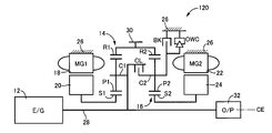
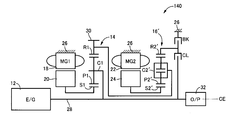
- FIG. 1 is a skeleton diagram illustrating the configuration of a hybrid vehicle drive device 10 (hereinafter simply referred to as drive device 10) to which the present invention is preferably applied.
- the drive device 10 of the present embodiment is a device for horizontal use that is preferably used in, for example, an FF (front engine front wheel drive) type vehicle and the like, and an engine 12, which is a main power source,
- the first electric motor MG1, the second electric motor MG2, the first planetary gear device 14 as a first differential mechanism, and the second planetary gear device 16 as a second differential mechanism are provided on a common central axis CE.
- the driving device 10 is configured substantially symmetrically with respect to the central axis CE, and the lower half of the central line is omitted in FIG. The same applies to each of the following embodiments.
- the engine 12 is, for example, an internal combustion engine such as a gasoline engine that generates driving force by combustion of fuel such as gasoline injected in a cylinder.
- the first electric motor MG1 and the second electric motor MG2 are preferably so-called motor generators each having a function as a motor (engine) for generating driving force and a generator (generator) for generating reaction force.
- Each stator (stator) 18, 22 is fixed to a housing (case) 26 that is a non-rotating member, and the rotor (rotor) 20, 24 is provided on the inner peripheral side of each stator 18, 22. Has been.
- the first planetary gear unit 14 is a single pinion type planetary gear unit having a gear ratio of ⁇ 1, and serves as a second rotating element that supports the sun gear S1 and the pinion gear P1 as the first rotating element so as to be capable of rotating and revolving.
- a ring gear R1 as a third rotating element that meshes with the sun gear S1 via the carrier C1 and the pinion gear P1 is provided as a rotating element (element).
- the second planetary gear device 16 is a single pinion type planetary gear device having a gear ratio of ⁇ 2, and serves as a second rotating element that supports the sun gear S2 and the pinion gear P2 as the first rotating element so as to be capable of rotating and revolving.
- a ring gear R2 as a third rotating element that meshes with the sun gear S2 via the carrier C2 and the pinion gear P2 is provided as a rotating element (element).
- the sun gear S1 of the first planetary gear unit 14 is connected to the rotor 20 of the first electric motor MG1.
- the carrier C1 of the first planetary gear unit 14 is connected to an input shaft 28 that is rotated integrally with the crankshaft of the engine 12.
- the input shaft 28 is centered on the central axis CE.
- the direction of the central axis of the central axis CE is referred to as an axial direction (axial direction) unless otherwise distinguished.
- the ring gear R1 of the first planetary gear device 14 is connected to an output gear 30 that is an output rotating member, and is also connected to the ring gear R2 of the second planetary gear device 16.
- the sun gear S2 of the second planetary gear device 16 is connected to the rotor 24 of the second electric motor MG2.
- the driving force output from the output gear 30 is transmitted to a pair of left and right driving wheels (not shown) via a differential gear device and an axle (not shown).
- torque input to the drive wheels from the road surface of the vehicle is transmitted (input) from the output gear 30 to the drive device 10 via the differential gear device and the axle.
- a mechanical oil pump 32 such as a vane pump is connected to an end portion of the input shaft 28 opposite to the engine 12, and an original pressure of a hydraulic control circuit 60 or the like to be described later when the engine 12 is driven.
- the hydraulic pressure is output.
- an electric oil pump driven by electric energy may be provided.
- the carrier C1 of the first planetary gear device 14 and the carrier C2 of the second planetary gear device 16 are selectively engaged between the carriers C1 and C2 (between the carriers C1 and C2).
- a clutch CL is provided.
- a brake BK for selectively engaging (fixing) the carrier C2 with respect to the housing 26 is provided between the carrier C2 of the second planetary gear device 16 and the housing 26 which is a non-rotating member.
- the clutch CL and the brake BK are preferably hydraulic engagement devices whose engagement states are controlled (engaged or released) according to the hydraulic pressure supplied from the hydraulic control circuit 60.
- a wet multi-plate friction engagement device or the like is preferably used, but a meshing engagement device, that is, a so-called dog clutch (meshing clutch) may be used.
- an engagement state may be controlled (engaged or released) according to an electrical command supplied from the electronic control device 40, such as an electromagnetic clutch or a magnetic powder clutch.
- the first planetary gear device 14 and the second planetary gear device 16 are arranged coaxially with the input shaft 28 (on the central axis CE), and , Are arranged at positions facing each other in the axial direction of the central axis CE. That is, with respect to the axial direction of the central axis CE, the first planetary gear device 14 is disposed on the engine 12 side with respect to the second planetary gear device 16. With respect to the axial direction of the central axis CE, the first electric motor MG1 is disposed on the engine 12 side with respect to the first planetary gear unit 14.
- the second electric motor MG1 is disposed on the opposite side of the engine 12 with respect to the second planetary gear device 16. That is, the first electric motor MG1 and the second electric motor MG2 are arranged at positions facing each other with the first planetary gear device 14 and the second planetary gear device 16 interposed therebetween with respect to the axial direction of the central axis CE. . That is, in the drive device 10, in the axial direction of the central axis CE, the first electric motor MG1, the first planetary gear device 14, the clutch CL, the second planetary gear device 16, the brake BK, Those components are arranged on the same axis in the order of the two electric motors MG2.
- FIG. 2 is a diagram for explaining a main part of a control system provided in the driving device 10 in order to control the driving of the driving device 10.
- the electronic control unit 40 shown in FIG. 2 includes a CPU, a ROM, a RAM, an input / output interface, and the like, and executes signal processing in accordance with a program stored in advance in the ROM while using a temporary storage function of the RAM.
- the microcomputer is a so-called microcomputer, and executes various controls related to driving of the drive device 10 including drive control of the engine 12 and hybrid drive control related to the first electric motor MG1 and the second electric motor MG2. That is, in this embodiment, the electronic control device 40 corresponds to a drive control device for a hybrid vehicle to which the drive device 10 is applied.
- the electronic control device 40 is configured as an individual control device for each control as required, such as for output control of the engine 12 and for operation control of the first electric motor MG1 and the second electric motor MG2.
- the electronic control device 40 is configured to be supplied with various signals from sensors, switches, and the like provided in each part of the driving device 10. That is, a signal representing an accelerator opening degree A CC which is an operation amount of an accelerator pedal (not shown) corresponding to a driver's output request amount by the accelerator opening sensor 42, and an engine which is the rotation speed of the engine 12 by the engine rotation speed sensor signal representative of the rotational speed N E, a signal indicative of the rotational speed N MG1 of the first electric motor MG1 by MG1 rotational speed sensor 46, a signal indicative of the rotational speed N MG2 of the second electric motor MG2 by MG2 rotational speed sensor 48, output rotation A signal representing the rotational speed N OUT of the output gear 30 corresponding to the vehicle speed V by the speed sensor 50, a signal representing the speed N W of each wheel in the driving device 10 by the wheel speed sensor 52, and a battery SOC sensor 54 A signal indicating the charge capacity (charge state) SOC of the battery that is not Is supplied to
- the electronic control device 40 is configured to output an operation command to each part of the driving device 10. That is, as an engine output control command for controlling the output of the engine 12, a fuel injection amount signal for controlling a fuel supply amount to an intake pipe or the like by the fuel injection device, and an ignition timing (ignition timing) of the engine 12 by the ignition device.
- An ignition signal to be commanded, an electronic throttle valve drive signal supplied to the throttle actuator for operating the throttle valve opening ⁇ TH of the electronic throttle valve, and the like are output to an engine control device 56 that controls the output of the engine 12.
- the A command signal for commanding the operation of the first motor MG1 and the second motor MG2 is output to the inverter 58, and electric energy corresponding to the command signal is transmitted from the battery via the inverter 58 to the first motor MG1 and the second motor.
- the output (torque) of the first electric motor MG1 and the second electric motor MG2 is controlled by being supplied to MG2.
- Electric energy generated by the first electric motor MG1 and the second electric motor MG2 is supplied to the battery via the inverter 58 and stored in the battery.
- a command signal for controlling the engagement state of the clutch CL and the brake BK is supplied to an electromagnetic control valve such as a linear solenoid valve provided in the hydraulic control circuit 60, and the hydraulic pressure output from the electromagnetic control valve is controlled.
- an electromagnetic control valve such as a linear solenoid valve provided in the hydraulic control circuit 60
- the drive device 10 functions as an electric differential unit that controls the differential state between the input rotation speed and the output rotation speed by controlling the operation state via the first electric motor MG1 and the second electric motor MG2.
- the electric energy generated by the first electric motor MG1 is supplied to the battery and the second electric motor MG2 via the inverter 58.
- the main part of the power of the engine 12 is mechanically transmitted to the output gear 30, while a part of the power is consumed for power generation of the first electric motor MG 1 and is converted into electric energy there.
- the electric energy is supplied to the second electric motor MG2 through the inverter 58.
- the second electric motor MG2 is driven, and the power output from the second electric motor MG2 is transmitted to the output gear 30.
- Electrical path from conversion of part of the power of the engine 12 into electrical energy and conversion of the electrical energy into mechanical energy by related equipment from the generation of the electrical energy to consumption by the second electric motor MG2. Is configured.
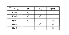
- FIG. 3 is an engagement table showing the engagement states of the clutch CL and the brake BK in each of the five types of travel modes established in the drive device 10, wherein the engagement is “ ⁇ ” and the release is blank. Show. In each of the travel modes “EV-1” and “EV-2” shown in FIG. 3, the operation of the engine 12 is stopped, and at least one of the first electric motor MG1 and the second electric motor MG2 is used for traveling. This is an EV travel mode used as a drive source.
- HV-1”, “HV-2”, and “HV-3” all drive the engine 12 as a driving source for traveling, for example, and the first motor MG1 and the second motor MG2 as required.
- This is a hybrid travel mode for driving or generating power.
- a reaction force may be generated by at least one of the first electric motor MG1 and the second electric motor MG2, or may be idled in an unloaded state.
- the operation of the engine 12 is stopped, and in the EV traveling mode in which at least one of the first electric motor MG ⁇ b> 1 and the second electric motor MG ⁇ b> 2 is used as a driving source for traveling.
- mode 1 travel mode 1
- 2 travel mode 2
- the brake BK is engaged.
- HV-1 which is mode 3 (travel mode 3) by releasing the clutch CL
- mode 4 travel mode 4
- HV-2 is established
- HV-3 which is mode 5 (travel mode 5) is established by releasing both the brake BK and the clutch CL.
- FIGS. 4 to 7 show the rotation elements of the driving device 10 (the first planetary gear device 14 and the second planetary gear device 16) that have different coupling states depending on the engagement states of the clutch CL and the brake BK.
- FIG. 2 shows a collinear chart that can represent the relative relationship of rotational speed on a straight line, showing the relative relationship of the gear ratio ⁇ of the first planetary gear device 14 and the second planetary gear device 16 in the horizontal axis direction, It is a two-dimensional coordinate which shows a relative rotational speed in an axial direction.
- the rotational speeds of the output gears 30 when the vehicle moves forward are represented as positive directions (positive rotations).
- a horizontal line X1 indicates zero rotation speed.
- the solid line Y1 indicates the sun gear S1 (first electric motor MG1) of the first planetary gear unit 14, the broken line Y2 indicates the sun gear S2 (second electric motor MG2) of the second planetary gear unit 16,
- the solid line Y3 is the carrier C1 (engine 12) of the first planetary gear unit 14, the broken line Y3 'is the carrier C2 of the second planetary gear unit 16, and the solid line Y4 is the ring gear R1 (output gear 30) of the first planetary gear unit 14.
- the broken line Y4 ′ indicates the relative rotational speed of each ring gear R2 of the second planetary gear unit 16.
- the relative rotational speeds of the three rotating elements in the first planetary gear device 14 are indicated by a solid line L1
- the relative rotational speeds of the three rotating elements in the second planetary gear device 16 are indicated by solid lines L1.
- Each is indicated by a broken line L2.
- the intervals between the vertical lines Y1 to Y4 (Y2 to Y4 ′) are determined according to the gear ratios ⁇ 1 and ⁇ 2 of the first planetary gear device 14 and the second planetary gear device 16. That is, regarding the vertical lines Y1, Y3, Y4 corresponding to the three rotating elements in the first planetary gear device 14, the space between the sun gear S1 and the carrier C1 corresponds to 1, and the carrier C1 and the ring gear R1 The interval corresponds to ⁇ 1.
- the gear ratio ⁇ 2 of the second planetary gear device 16 is preferably larger than the gear ratio ⁇ 1 of the first planetary gear device 14 ( ⁇ 2> ⁇ 1).
- EV-1 shown in FIG. 3 corresponds to mode 1 (travel mode 1) in the drive device 10, and preferably the operation of the engine 12 is stopped and the second electric motor MG2 is stopped. Is an EV traveling mode used as a driving source for traveling.
- FIG. 4 is a collinear diagram corresponding to this mode 1, and will be described using this collinear diagram.
- the clutch CL is released, the carrier C1 and the second planetary gear device 14 of the first planetary gear unit 14 are disengaged.
- the planetary gear device 16 can rotate relative to the carrier C2.
- Engagement of the brake BK causes the carrier C2 of the second planetary gear device 16 to be connected (fixed) to the housing 26, which is a non-rotating member, so that its rotational speed is zero.
- the rotation direction of the sun gear S2 and the rotation direction of the ring gear R2 are opposite to each other, and negative torque (torque in the negative direction) is generated by the second electric motor MG2.
- the torque causes the ring gear R2, that is, the output gear 30, to rotate in the positive direction. That is, by outputting negative torque by the second electric motor MG2, the hybrid vehicle to which the drive device 10 is applied can be caused to travel forward.
- the first electric motor MG1 is idled.
- the relative rotation of the carriers C1 and C2 is allowed, and EV travel control similar to EV travel in a vehicle equipped with a so-called THS (Toyota Hybrid System) in which the carrier C2 is connected to a non-rotating member. It can be performed.
- THS Toyota Hybrid System
- FIG. 3 corresponds to mode 2 (traveling mode 2) in the driving apparatus 10, and preferably the operation of the engine 12 is stopped and the first electric motor MG1 is stopped.
- this is an EV traveling mode in which at least one of the second electric motor MG2 is used as a driving source for traveling.
- FIG. 5 is a collinear diagram corresponding to this mode 2. If the collinear diagram is used to explain, the carrier C1 of the first planetary gear device 14 and the first planetary gear device 14 are engaged by engaging the clutch CL. The relative rotation of the two planetary gear unit 16 with the carrier C2 is disabled.
- the carrier C2 of the second planetary gear device 16 and the carrier C1 of the first planetary gear device 14 engaged with the carrier C2 are non-rotating members. Are connected (fixed) to each other and their rotational speed is zero.
- the rotation direction of the sun gear S1 is opposite to the rotation direction of the ring gear R1 in the first planetary gear device 14, and the rotation of the sun gear S2 is reversed in the second planetary gear device 16.
- the direction and the rotation direction of the ring gear R2 are opposite to each other.
- the hybrid vehicle to which the drive device 10 is applied can be caused to travel forward by outputting negative torque by at least one of the first electric motor MG1 and the second electric motor MG2.
- the mode 2 it is possible to establish a mode in which power generation is performed by at least one of the first electric motor MG1 and the second electric motor MG2.
- HV-1 shown in FIG. 3 corresponds to mode 3 (traveling mode 3) in the driving device 10, and is preferably used as a driving source for traveling when the engine 12 is driven. This is a hybrid travel mode in which driving or power generation is performed by the first electric motor MG1 and the second electric motor MG2 as necessary.
- the collinear diagram of FIG. 4 also corresponds to this mode 3. If described using this collinear diagram, the carrier C1 of the first planetary gear device 14 and the carrier C1 are released by releasing the clutch CL. The second planetary gear device 16 can rotate relative to the carrier C2.
- “HV-2” shown in FIG. 3 corresponds to mode 4 (travel mode 4) in the drive device 10, and is preferably used as a drive source for travel when the engine 12 is driven.
- This is a hybrid travel mode in which driving or power generation is performed by the first electric motor MG1 and the second electric motor MG2 as necessary.
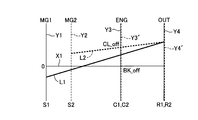
- FIG. 6 is a collinear diagram corresponding to the mode 4, and will be described using this collinear diagram.
- the ring gears R1 and R2 Since the ring gears R1 and R2 are connected to each other, the ring gears R1 and R2 operate as one rotating element that is rotated integrally. That is, in the mode 4, the rotating elements in the first planetary gear device 14 and the second planetary gear device 16 in the driving device 10 function as a differential mechanism including four rotating elements as a whole. That is, four gears in order from the left in FIG. 6 are the sun gear S1 (first electric motor MG1), the sun gear S2 (second electric motor MG2), the carriers C1 and C2 (engine 12) connected to each other, A composite split mode is obtained in which ring gears R1 and R2 (output gear 30) connected to each other are connected in this order.
- the arrangement order of the rotating elements in the first planetary gear device 14 and the second planetary gear device 16 in the alignment chart is a sun gear S1 indicated by a vertical line Y1.
- the sun gear S2 indicated by the vertical line Y2, the carriers C1 and C2 indicated by the vertical line Y3 (Y3 ′), and the ring gears R1 and R2 indicated by the vertical line Y4 (Y4 ′) are arranged in this order.
- the gear ratios ⁇ 1 and ⁇ 2 of the first planetary gear device 14 and the second planetary gear device 16 are respectively shown in FIG.
- the line Y2 is arranged in the above-described order, that is, the interval between the vertical line Y1 and the vertical line Y3 is wider than the interval between the vertical line Y2 and the vertical line Y3 ′.
- the sun gears S1 and S2 and the carriers C1 and C2 correspond to 1
- the carriers C1 and C2 and the ring gears R1 and R2 correspond to ⁇ 1 and ⁇ 2.
- the gear ratio ⁇ 2 of the second planetary gear device 16 is larger than the gear ratio ⁇ 1 of the first planetary gear device 14.
- the carrier C1 of the first planetary gear device 14 and the carrier C2 of the second planetary gear device 16 are connected, and the carriers C1 and C2 are connected to each other. It can be rotated integrally.
- the reaction force can be applied to the output of the engine 12 by either the first electric motor MG1 or the second electric motor MG2. That is, when the engine 12 is driven, the reaction force can be shared by one or both of the first electric motor MG1 and the second electric motor MG2, and the engine 12 can be operated at an efficient operating point, or the torque caused by heat. It is possible to run to ease restrictions such as restrictions.
- the reaction force torque for transmitting the output of the engine 12 to the output gear 30 is output by the first electric motor MG1 and the second electric motor MG2, and the reaction force torque of the first electric motor MG1 and the second electric motor MG2 is output.
- the sharing ratio can be changed. For example, the efficiency can be improved by controlling the first motor MG1 and the second motor MG2 to receive the reaction force preferentially by the motor that can operate efficiently. Further, when torque is limited by heat in either the first electric motor MG1 or the second electric motor MG2, the driving force is assisted by regeneration or output of an electric motor that is not torque limited, so that the engine 12 It is possible to ensure a reaction force necessary for driving.
- “HV-3” shown in FIG. 3 corresponds to mode 5 (traveling mode 5) in the driving device 10, and is preferably used as a driving source for traveling when the engine 12 is driven.
- This is a hybrid travel mode in which driving or power generation is performed by the first electric motor MG1 as necessary.
- FIG. 7 is a collinear diagram corresponding to this mode 5. If described with reference to this collinear diagram, the carrier C1 of the first planetary gear unit 14 and the second planetary gear device 14 are released by releasing the clutch CL.
- the planetary gear device 16 can rotate relative to the carrier C2.
- the carrier C2 of the second planetary gear device 16 can be rotated relative to the housing 26, which is a non-rotating member.
- the second electric motor MG2 can be disconnected from the drive system (power transmission path) and stopped.
- the second electric motor MG2 is always rotated with the rotation of the output gear 30 (ring gear R2) when the vehicle is traveling.
- the rotation speed of the second electric motor MG2 reaches a limit value (upper limit value), or the rotation speed of the ring gear R2 is increased and transmitted to the sun gear S2. Therefore, from the viewpoint of improving efficiency, it is not always preferable to always rotate the second electric motor MG2 at a relatively high vehicle speed.
- the second motor MG2 is driven by the engine 12 and the first motor MG1 by separating the second motor MG2 from the drive system at a relatively high vehicle speed, thereby driving the second motor MG2.
- the clutch CL and the brake BK are engaged or released in combination.
- Three modes of HV-1 (mode 3), HV-2 (mode 4), and HV-3 (mode 5) can be selectively established. Thereby, for example, by selectively establishing the mode with the highest transmission efficiency among these three modes according to the vehicle speed, the gear ratio, etc. of the vehicle, it is possible to improve the transmission efficiency and thus improve the fuel efficiency. it can.
- FIG. 8 is a functional block diagram for explaining the main part of the control function provided in the electronic control unit 40.
- the traveling mode determination unit 70 shown in FIG. 8 determines a traveling mode that is established in the drive device 10. Basically, from a predetermined relationship, the accelerator opening A CC detected by the accelerator opening sensor 42, the vehicle speed V corresponding to the output rotation speed N OUT detected by the output rotation speed sensor 50, and Based on the battery SOC or the like detected by the battery SOC sensor 54, it is determined whether any one of the modes 1 to 5 described above with reference to FIG. Preferably, when the battery SOC detected by the battery SOC sensor 54 is less than a predetermined threshold, the mode is a hybrid travel mode in which the engine 12 is driven and used as a drive source for travel.
- the battery SOC detected by the battery SOC sensor 54 is equal to or greater than the threshold value, it is determined whether or not the mode 1 or the mode 2 that is the EV traveling mode in which the engine 12 is stopped is established.
- the vehicle speed V corresponding to the output rotational speed N OUT detected by the output rotational speed sensor 50 when the vehicle starts is zero.
- an unillustrated brake pedal off operation an operation to release the brake pedal depression
- the engine 12 is stopped and the first electric motor MG1 or the like is exclusively used as a driving source for traveling. It is determined whether the mode 1 or the like that is the traveling mode is established.
- a traveling mode for improving the transmission efficiency and the fuel consumption of the engine 12 is appropriately selected.
- the electric motor operation control unit 72 controls the operation of the first electric motor MG1 and the second electric motor MG2 via the inverter 58. Specifically, by controlling the electric energy supplied from the battery (not shown) to the first electric motor MG1 and the second electric motor MG2 via the inverter 58, the necessary output by the first electric motor MG1 and the second electric motor MG2 That is, control is performed so that a target torque (target motor output) is obtained.
- a target torque target motor output
- the torque sharing ratio control unit 74 controls the torque sharing ratio of the first motor MG1 and the second motor MG2 in a state where both the first motor MG1 and the second motor MG2 are operated. For example, in the mode 4, that is, in a state where the engine 12 is driven, the clutch CL is engaged and the brake BK is released, the first motor MG 1 and the second motor MG 2 share the output of the engine 12. When the reaction force is received, the reaction torque sharing ratio of the first motor MG1 and the second motor MG2 is controlled.
- the torque sharing ratio control unit 74 includes a MG1 target torque calculation unit 76 that calculates a target torque (target first motor output) T MG1 * of the first motor MG1, and the second motor. And an MG2 target torque calculator 78 for calculating a target torque (target first motor output) TMG2 * of MG2.
- the torque sharing ratio control unit 74 is preferably based on the engine torque T E and the like outputted from the required driving force and the engine 12 of the drive device 10, an output by the first electric motor MG1 and the second motor MG2
- the reaction force torque to be performed that is, the reaction force torque necessary for realizing the required driving force with respect to the output of the engine 12, is calculated, and the first electric motor MG1 and the second electric motor MG2 are compared with the reaction force torque.
- the reaction torque sharing ratio is calculated.
- the required driving force is, for example, an accelerator opening degree A CC detected by the accelerator opening degree sensor 42 and a vehicle speed V corresponding to an output rotation speed detected by the output rotation speed sensor 50 from a predetermined relationship.
- the engine torque TE is calculated (estimated) based on, for example, an intake air amount Q A of the engine 12 detected by an intake air amount sensor (not shown) based on a predetermined relationship.
- the torque sharing ratio control unit 74 preferably controls the reaction force torque by the first electric motor and the second electric motor so that the required driving force is realized with respect to the output of the engine 12.
- the first electric motor MG1 and the second electric motor MG1 and the second electric motor MG12 are operated at an efficient operating point, and the first electric motor MG1 and the second electric motor MG2 are allowed to run such that a restriction such as torque limitation due to heat is relaxed.
- the reaction torque sharing ratio of the electric motor MG2 is controlled.
- the MG1 target torque calculation unit 76 sets the target torque (target first motor output) T MG1 * of the first electric motor MG1 to the MG2 target torque calculation unit so that the torque sharing ratio is realized.
- the target torque (target first motor output) T MG2 * of the second electric motor MG2 is calculated.
- the abnormal noise generation determination unit 80 generates or generates abnormal noise such as rattling noise in the first planetary gear device 14 and the second planetary gear device 16 when the hybrid travel mode for driving the engine 12 is established. Determine if there is a risk of occurrence.
- abnormal noise such as rattling noise in the first planetary gear device 14 and the second planetary gear device 16 when the hybrid travel mode for driving the engine 12 is established.
- the gear engaging force in the second planetary gear device 16 for example, the sun gear S2
- the pinion gear P2 mesh with each other
- a rattling noise due to engine torque fluctuation may occur.
- the reaction force torque of one of the electric motors is relatively small and may take a value near zero.
- the abnormal noise occurrence determination unit 80 is preferably configured so that at least one of the reaction force torques output by the first electric motor MG1 and the second electric motor MG2 is within a predetermined abnormal noise generation region including zero. In some cases, it is determined that there is a possibility of the generation or generation of the abnormal noise.
- the motor torque that is the object of this determination is the target torque T MG1 * , T MG2 * calculated by the MG1 target torque calculation unit 76 and MG2 target torque calculation unit 78, or the motor rotation speed from a predetermined relationship. This is a torque estimated value calculated based on this.
- the probability that the motor torque enters the abnormal sound generation region is predicted from the accelerator opening degree A CC detected by the accelerator opening sensor 42, the change gradient of the electric motor torque, and the like before actually entering the abnormal noise generation region. You may determine (detect) the possibility that abnormal noise will generate
- FIG. 9 is a diagram illustrating an example of an abnormal sound generation area used for determination by the abnormal sound generation determination unit 80.
- an abnormal noise generation region is set individually corresponding to each of the first electric motor MG1 and the second electric motor MG2, but for convenience of explanation, one relationship is illustrated as an example.
- the upper limit value of the abnormal noise generation region is indicated by a one-dot chain line
- the lower limit value is indicated by a two-dot chain line
- the torque zero is indicated by a broken line
- the solid line indicates a change with time of the motor torque.
- the abnormal sound generation region is preferably a minute range up to an upper limit value indicated by a one-dot chain line on the positive side, with two points on the negative side, with the motor torque zero indicated by a broken line as the center.
- Each numerical range is a minute range up to the lower limit indicated by a chain line.
- This abnormal noise generation region is preferably determined in advance according to the configuration (hardware characteristics) of the first electric motor MG1, the second electric motor MG2, the first planetary gear device 14, the second planetary gear device 16, and the like.
- the relationship (map) is determined by the accelerator opening degree A CC detected by the accelerator opening degree sensor 42, the vehicle speed V corresponding to the output rotation speed detected by the output rotation speed sensor 50, and an oil temperature sensor (not shown).
- the relationship calculated in real time from the transmission oil temperature detected by the engine, the cooling water temperature of the engine 12 detected by a water temperature sensor (not shown), etc. is calculated (set) every time the abnormal sound generation determination unit 80 determines. And may be used.
- the motor torque indicated by the solid line is in the abnormal noise generation region between time points t2 and t3. In this case, it is determined (detected) whether or not an abnormal noise is generated in the determination at time t3.
- the torque sharing ratio control unit 74 changes the reaction force torque sharing ratio of the first electric motor MG1 and the second electric motor MG2 when it is determined by the abnormal sound generation determination unit 80 that the abnormal sound is generated or may be generated ( Adjust).
- the first electric motor MG1 and the second electric motor MG2 are configured such that at least one of the reaction force torques output by the first electric motor MG1 and the second electric motor MG2 is outside the abnormal sound generation region.
- the reaction torque sharing ratio of the motor is corrected (increased or decreased).
- the correction amount is compensated by the other electric motor, so that the driving force output from the output gear 30 is controlled to realize the required driving force.
- a conversion value corresponding to the gear ratio of the first planetary gear unit 14 and the second planetary gear unit 16 is used as the correction value.
- the driving force output from the output gear 30 can be maintained by adding a value obtained by multiplying the coefficient for conversion to () to the reaction torque of the other motor.
- the MG1 target torque calculation unit 76 and the MG2 target torque calculation unit 78 preferably have a motor torque at the present time (first motor) when the abnormal sound generation determination unit 80 determines that abnormal noise is generated or is likely to occur.
- Torque T MG1 , second motor torque T MG2 ) and the upper limit value and lower limit value of the abnormal noise generation area, respectively, and the smaller difference (upper limit value or lower limit value) is calculated as the target torque.
- the upper limit value is set as the target torque of the motor related to torque correction.
- the lower limit value is set as the target torque of the motor related to torque correction.
- the difference dtu from the value is compared, the difference dto from the upper limit value is smaller. Accordingly, when it is determined that the noise generation region has been entered at time t3, the upper limit value of the noise generation region indicated by the alternate long and short dash line in the figure is set as the target torque of the electric motor related to torque correction.
- the torque sharing ratio may be corrected according to the battery SOC detected by the battery SOC sensor 54, the charge / discharge limit value of the battery, or the like. For example, when the charge amount of the battery is relatively high and close to the charge limit value, the torque sharing ratio is adjusted so that the operations of the first motor MG1 and the second motor MG2 are on the discharge side (the power generation amount is reduced). It is conceivable to control such as.
- the motor operation control unit 72 controls the operation of the first electric motor MG1 and the second electric motor MG2 based on the torque sharing ratio calculated by the torque sharing ratio control unit 74.
- the first motor target torque T MG1 * and the second motor target torque T MG2 * calculated by the MG1 target torque calculation unit 76 and the MG2 target torque calculation unit 78 are achieved via the inverter 58.
- the operation of the first electric motor MG1 and the second electric motor MG2 is controlled.
- this control when the target torque is changed by at least one of the MG1 target torque calculation unit 76 and the MG2 target torque calculation unit 78, in order to suppress generation of new abnormal noise such as rattling noise due to a sudden change in the motor torque.
- a control may be performed to limit the change gradient (time change rate) of the motor torque to be a predetermined value or less.
- the target torque of the electric motor that has been previously determined to be within the abnormal noise generation region. Is corrected (corrected so that it is outside the range), and the target torque of the other motor is corrected according to the correction amount, thereby controlling both motor torques to be outside the abnormal noise generation region. There may be.
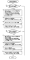
- FIG. 10 is a flowchart for explaining a main part of the abnormal sound generation suppression control by the electronic control unit 40, and is repeatedly executed at a predetermined cycle.
- the case where the output torque of the first electric motor MG1 enters the abnormal noise generation region will be described as a representative.
- the control in which the first electric motor MG1 and the second electric motor MG2 in FIG. 10 are replaced is executed. This is the same in FIG. 11 described later.
- step (hereinafter, step is omitted) S1 it is determined whether or not the torque T MG1 (base value) of the first electric motor MG1 is within a specified abnormal noise generation region. If the determination in S1 is negative, the routine is terminated accordingly. If the determination in S1 is affirmative, the torque T MG1 of the first electric motor MG1 is generated in S2 in S2.
- Target torque T MG1 * is set so as to be out of the region. For example, the difference between the first motor torque T MG1 and the upper limit value and lower limit value of the abnormal noise generation region is calculated, and the smaller difference is set as the target torque T MG1 * .
- the necessary correction amount of the first electric motor MG1 torque is calculated based on the target torque TMG1 * calculated in S2. That is, the difference between the target torque T MG1 * calculated in S2 and the first motor torque T MG1 (base value) is calculated.
- a control is performed in which the correction amount calculated in S3 is added to the torque T MG1 (base value).
- the conversion value (first value) corresponding to the gear ratio of the first planetary gear device 14 and the second planetary gear device 16 is added to the correction value calculated in S3.
- This routine is terminated after control is performed in which a value obtained by multiplying a coefficient for conversion from the motor side to the second motor side is added to the torque MG2 (base value) of the second motor MG2.
- FIG. 11 is a flowchart for explaining a main part of another abnormal noise suppression control by the electronic control device 40, and is repeatedly executed at a predetermined cycle.
- steps common to the control in FIG. 10 described above are denoted by the same reference numerals and description thereof is omitted.
- the necessary re-correction amount of the second electric motor MG2 torque is calculated based on the target torque TMG2 * calculated in S7. That is, the difference between the target torque T MG2 * calculated in S7 and the second motor torque T MG1 (correction value) is calculated.
- a control is performed in which the re-correction amount calculated in S8 is added to the torque T MG2 (correction value).
- the re-correction value calculated in S8 is converted into a conversion value (first value according to the gear ratio of the first planetary gear device 14 and the second planetary gear device 16).
- S4, S5, S9, and S10 are operations of the motor operation control unit 72
- S2, S3, S7, and S8 are operations of the torque sharing ratio control unit 74
- S2 is the MG1 target torque
- the operation of the calculation unit 76 corresponds to the operation of the MG2 target torque calculation unit 78
- S1 and S6 correspond to the operation of the abnormal sound generation determination unit 80, respectively.
- the drive control device for a hybrid vehicle according to the present invention is the first electric motor MG1, the first planetary gear device 14, and the second
- the present invention is also preferably applied to a configuration in which the arrangement (arrangement) of the electric motor MG2, the second planetary gear device 16, the clutch CL, and the brake BK is changed.
- the carrier C2 is allowed to rotate in one direction with respect to the housing 26 between the carrier C2 of the second planetary gear device 16 and the housing 26 which is a non-rotating member.
- the present invention is also preferably applied to a configuration in which a one-way clutch (one-way clutch) OWC that prevents reverse rotation is provided in parallel with the brake BK.
- a one-way clutch one-way clutch
- OWC one-way clutch
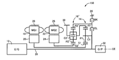
- As an alternative to the single-pinion type second planetary gear unit 16 such as a driving unit 130 shown in FIG. 15, a driving unit 140 shown in FIG. 16, and a driving unit 150 shown in FIG.
- the present invention is also preferably applied to a configuration including a pinion type second planetary gear device 16 '.
- the second planetary gear device 16 ' includes a sun gear S2' as a first rotation element, a carrier C2 'as a second rotation element that supports a plurality of pinion gears P2' meshed with each other so as to rotate and revolve, and a pinion gear.
- a ring gear R2 ′ as a third rotating element meshing with the sun gear S2 ′ via P2 ′ is provided as a rotating element (element).
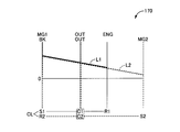
- FIG. 18 to 20 are collinear diagrams illustrating the configuration and operation of other hybrid vehicle drive devices 160, 170, and 180 to which the present invention is preferably applied as an alternative to the drive device 10.
- FIG. 18 to 20 the relative rotational speeds of the sun gear S1, the carrier C1, and the ring gear R1 in the first planetary gear device 14 are indicated by the solid line L1 as in the collinear charts of FIGS.
- the relative rotational speeds of the sun gear S2, the carrier C2, and the ring gear R2 in the second planetary gear device 16 are indicated by broken lines L2.
- the sun gear S1, the carrier C1, and the ring gear R1 of the first planetary gear device 14 are connected to the first electric motor MG1, the engine 12, and the second electric motor MG2, respectively.
- the sun gear S2, the carrier C2, and the ring gear R2 of the second planetary gear device 16 are connected to the housing 26 via the second electric motor MG2, the output gear 30, and the brake BK, respectively.
- the sun gear S1 and the ring gear R2 are selectively connected via the clutch CL.
- the ring gear R1 and the sun gear S2 are connected to each other.
- the sun gear S1, the carrier C1, and the ring gear R1 of the first planetary gear device 14 are connected to the first electric motor MG1, the output gear 30, and the engine 12, respectively.
- the sun gear S2, the carrier C2, and the ring gear R2 of the second planetary gear device 16 are connected to the housing 26 via the second electric motor MG2, the output gear 30, and the brake BK, respectively.
- the sun gear S1 and the ring gear R2 are selectively connected via the clutch CL.
- the clutches C1 and C2 are connected to each other.
- the sun gear S1, the carrier C1, and the ring gear R1 of the first planetary gear device 14 are connected to the first electric motor MG1, the output gear 30, and the engine 12, respectively.
- the sun gear S2, the carrier C2, and the ring gear R2 of the second planetary gear device 16 are connected to the housing 26 and the output gear 30 through the second electric motor MG2 and the brake BK, respectively.
- the ring gear R1 and the carrier C2 are selectively connected via a clutch CL.
- the carrier C1 and the ring gear R2 are connected to each other.
- the first difference having four rotating elements (expressed as four rotating elements) on the collinear chart is the same as the embodiment shown in FIGS.
- a rotating element is selectively connected via a clutch CL, and the rotating element of the second planetary gear devices 16 and 16 'to be engaged by the clutch CL is braked against the housing 26 which is a non-rotating member.
- a BK In that it is a drive control apparatus for a hybrid vehicle which is selectively connected Te, it is common. That is, the hybrid vehicle drive control apparatus of the present invention described above with reference to FIG. 8 and the like is also preferably applied to the configurations shown in FIGS.
- the clutch CL there are four rotating elements as a whole in a state in which the clutch CL is engaged (represented as four rotating elements on the collinear chart shown in FIGS. 4 to 7 and the like).
- the first planetary gear unit 14 that is the first differential mechanism and the second planetary gear units 16 and 16 'that are the second differential mechanism, and the engine 12 and the first electric motor MG1 that are respectively connected to these four rotating elements.
- a second electric motor MG2, and an output gear 30 that is an output rotation member, and one of the four rotation elements is a rotation element of the first differential mechanism and a rotation of the second differential mechanism.
- HV-2 brake BK Mode 4
- HV-2 a drive control device for a hybrid vehicle that is selectively coupled, and that drives the engine 12
- engages the clutch CL and releases the brake BK. Since the reaction force torque is output by the first electric motor MG1 and the second electric motor MG2 and the reaction torque sharing ratio of the first electric motor MG1 and the second electric motor MG2 is controlled.
- the gears in the differential mechanisms 14, 16 (16 ') Necessary and sufficient for the gears in the differential mechanisms 14, 16 (16 ') to mesh with each other by controlling the reaction torque of the first electric motor MG1 and the second electric motor MG2 in the hybrid travel mode in which the engine 12 is driven. Power can be ensured, and the occurrence of rattling noise due to engine torque fluctuations can be suitably suppressed. That is, it is possible to provide the electronic control device 40 as a drive control device for a hybrid vehicle that suppresses the generation of abnormal noise when the engine is driven.
- the first electric motor MG1 and the second electric motor MG2 are arranged so that at least one of the reaction force torques output by the first electric motor MG1 and the second electric motor MG2 is outside a specified abnormal noise generation region including zero. Since the torque sharing ratio is controlled, in the hybrid travel mode in which the engine 12 is driven, it is possible to suppress in a practical manner that the torque of the electric motor becomes minute, and generation of rattling noise due to engine torque fluctuations can be suppressed. It can suppress suitably.
- the first planetary gear unit 14 is connected to a sun gear S1 as a first rotating element connected to the first electric motor MG1, a carrier C1 as a second rotating element connected to the engine 12, and the output gear 30.
- the second planetary gear unit 16 (16 ′) includes a sun gear S2 (S2 ′), a second rotation element connected to the second electric motor MG2, and a second gear R1.
- a carrier C2 (C2 ′) as a rotating element and a ring gear R2 (R2 ′) as a third rotating element are provided, and any one of the carrier C2 (C2 ′) and the ring gear R2 (R2 ′) is the first planet.
- the clutch CL is connected to the ring gear R1 of the gear device 14, and the clutch CL includes the carrier C1 in the first planetary gear device 14 and the carrier C2 ( 2 ′) and the ring gear R2 (R2 ′), which is selectively engaged with the rotating element not connected to the ring gear R1, the brake BK includes the carrier C2 (C2 ′) and the ring gear.
- R2 (R2 ′), which is not connected to the ring gear R1, is selectively engaged with the housing 26, which is a non-rotating member. In the device 10 or the like, it is possible to suppress the generation of abnormal noise when the engine is driven.
Landscapes
- Engineering & Computer Science (AREA)
- Chemical & Material Sciences (AREA)
- Combustion & Propulsion (AREA)
- Transportation (AREA)
- Mechanical Engineering (AREA)
- Automation & Control Theory (AREA)
- Hybrid Electric Vehicles (AREA)
- Electric Propulsion And Braking For Vehicles (AREA)
Priority Applications (5)
| Application Number | Priority Date | Filing Date | Title |
|---|---|---|---|
| CN201280071661.2A CN104203692B (zh) | 2012-03-26 | 2012-03-26 | 混合动力车辆的驱动控制装置 |
| EP12872433.3A EP2832606B1 (en) | 2012-03-26 | 2012-03-26 | Hybrid vehicle drive control device |
| PCT/JP2012/057822 WO2013145103A1 (ja) | 2012-03-26 | 2012-03-26 | ハイブリッド車両の駆動制御装置 |
| US14/387,792 US9211886B2 (en) | 2012-03-26 | 2012-03-26 | Hybrid vehicle drive control device |
| JP2014507074A JP5971330B2 (ja) | 2012-03-26 | 2012-03-26 | ハイブリッド車両の駆動制御装置 |
Applications Claiming Priority (1)
| Application Number | Priority Date | Filing Date | Title |
|---|---|---|---|
| PCT/JP2012/057822 WO2013145103A1 (ja) | 2012-03-26 | 2012-03-26 | ハイブリッド車両の駆動制御装置 |
Publications (1)
| Publication Number | Publication Date |
|---|---|
| WO2013145103A1 true WO2013145103A1 (ja) | 2013-10-03 |
Family
ID=49258473
Family Applications (1)
| Application Number | Title | Priority Date | Filing Date |
|---|---|---|---|
| PCT/JP2012/057822 WO2013145103A1 (ja) | 2012-03-26 | 2012-03-26 | ハイブリッド車両の駆動制御装置 |
Country Status (5)
| Country | Link |
|---|---|
| US (1) | US9211886B2 (zh) |
| EP (1) | EP2832606B1 (zh) |
| JP (1) | JP5971330B2 (zh) |
| CN (1) | CN104203692B (zh) |
| WO (1) | WO2013145103A1 (zh) |
Cited By (1)
| Publication number | Priority date | Publication date | Assignee | Title |
|---|---|---|---|---|
| JP2015223915A (ja) * | 2014-05-27 | 2015-12-14 | トヨタ自動車株式会社 | ハイブリッド車両用駆動装置の制御装置 |
Families Citing this family (7)
| Publication number | Priority date | Publication date | Assignee | Title |
|---|---|---|---|---|
| CN104203700A (zh) * | 2012-03-26 | 2014-12-10 | 丰田自动车株式会社 | 混合动力车辆的驱动控制装置 |
| DE102013207680A1 (de) * | 2013-04-26 | 2014-10-30 | Deere & Company | Betriebsstrategie für Hydbridfahrzeuge zur Realisierung einer Lastpunktverschiebung, einer Rekuperation und eines Boost |
| US9421968B2 (en) * | 2013-12-18 | 2016-08-23 | Hyundai Motor Company | System and method for controlling torque for hybrid vehicle |
| JP2016109108A (ja) * | 2014-12-10 | 2016-06-20 | ローベルト ボッシュ ゲゼルシャフト ミット ベシュレンクテル ハフツング | 車両用のトルク制御装置およびトルク制御方法 |
| CN104786818B (zh) * | 2015-04-30 | 2017-05-24 | 重庆蓝黛动力传动机械股份有限公司 | 混合动力汽车混联式双行星轮系动力耦合装置及方法 |
| JP6569632B2 (ja) * | 2016-09-29 | 2019-09-04 | トヨタ自動車株式会社 | ハイブリッド車両の制御装置 |
| JP6861184B2 (ja) * | 2018-04-26 | 2021-04-21 | 株式会社豊田中央研究所 | 車両駆動装置 |
Citations (6)
| Publication number | Priority date | Publication date | Assignee | Title |
|---|---|---|---|---|
| JPH038183B2 (zh) | 1985-06-21 | 1991-02-05 | Kokichi Tanno | |
| JP2004254434A (ja) * | 2003-02-20 | 2004-09-09 | Toyota Motor Corp | 電動機の制御装置 |
| JP2005199942A (ja) * | 2004-01-19 | 2005-07-28 | Toyota Motor Corp | 動力出力装置およびこれを搭載する自動車並びに動力伝達装置 |
| JP2005318721A (ja) * | 2004-04-28 | 2005-11-10 | Toyota Motor Corp | ハイブリッド車両の駆動装置 |
| JP2006077859A (ja) * | 2004-09-08 | 2006-03-23 | Nissan Motor Co Ltd | ハイブリッド車の駆動装置 |
| JP2008265600A (ja) | 2007-04-23 | 2008-11-06 | Toyota Motor Corp | 車両およびその制御方法 |
Family Cites Families (23)
| Publication number | Priority date | Publication date | Assignee | Title |
|---|---|---|---|---|
| US7337869B2 (en) * | 2000-01-10 | 2008-03-04 | The United States Of America As Represented By The Administrator Of The United States Environmental Protection Agency | Hydraulic hybrid vehicle with integrated hydraulic drive module and four-wheel-drive, and method of operation thereof |
| US6590299B2 (en) * | 2001-11-08 | 2003-07-08 | Ford Global Technologies, Llc | Hybrid electric vehicle control strategy to provide vehicle creep and hill holding |
| JP3641243B2 (ja) * | 2002-02-26 | 2005-04-20 | 日産自動車株式会社 | ハイブリッド変速機 |
| JP3857669B2 (ja) * | 2002-09-04 | 2006-12-13 | 日産自動車株式会社 | ハイブリッド変速機 |
| JP3991975B2 (ja) * | 2003-11-12 | 2007-10-17 | 日産自動車株式会社 | ハイブリッド変速機の変速制御装置 |
| JP3864950B2 (ja) * | 2003-11-18 | 2007-01-10 | 日産自動車株式会社 | ハイブリッド変速機 |
| JP3858890B2 (ja) * | 2003-12-18 | 2006-12-20 | 日産自動車株式会社 | ハイブリッド変速機のモード切り替え制御装置 |
| US7004870B2 (en) * | 2004-02-25 | 2006-02-28 | Dana Corporation | Integrated torque and roll control system |
| EP1619063B1 (en) * | 2004-07-21 | 2009-10-14 | Nissan Motor Company, Limited | Motor torque control apparatus and method for automotive vehicle |
| JP2007001493A (ja) * | 2005-06-27 | 2007-01-11 | Nissan Motor Co Ltd | ハイブリッド車両の制御装置 |
| US7338401B2 (en) * | 2005-07-22 | 2008-03-04 | Gm Global Technology Operations, Inc. | Two mode electrically variable transmission with equal forward and reverse input-split modal and fixed ratio performance |
| US7398147B2 (en) * | 2005-08-02 | 2008-07-08 | Ford Global Technologies, Llc | Optimal engine operating power management strategy for a hybrid electric vehicle powertrain |
| CN100457497C (zh) * | 2005-10-27 | 2009-02-04 | 丰田自动车株式会社 | 用于混合动力车的驱动单元 |
| US7491144B2 (en) * | 2006-05-11 | 2009-02-17 | Gm Global Technology Operations, Inc. | Single mode, compound-split transmission with dual mechanical paths and fixed reduction ratio |
| US7575529B2 (en) * | 2006-09-13 | 2009-08-18 | Gm Global Technology Operations, Inc. | Hybrid electrically variable transmission with geared reverse mode using single motor/generator |
| DE102006059591A1 (de) * | 2006-12-16 | 2008-06-19 | Zf Friedrichshafen Ag | Hybridantriebsstrang eines Kraftfahrzeugs |
| US8182391B2 (en) * | 2008-05-21 | 2012-05-22 | GM Global Technology Operations LLC | Electric torque converter for a powertrain and method of operating a vehicle |
| US8556760B2 (en) * | 2008-11-07 | 2013-10-15 | Noel R. Mack | Electric drive two-speed transaxle |
| KR101509799B1 (ko) * | 2009-11-12 | 2015-04-06 | 현대자동차주식회사 | 하이브리드 차량의 변속기 |
| KR101496105B1 (ko) * | 2011-07-01 | 2015-02-25 | 쟈트코 가부시키가이샤 | 하이브리드 차량의 제어 장치 |
| AU2011373822A1 (en) | 2011-07-27 | 2014-02-20 | Toyota Jidosha Kabushiki Kaisha | Drive device for hybrid vehicle |
| KR101795377B1 (ko) * | 2012-04-19 | 2017-11-10 | 현대자동차 주식회사 | 하이브리드 차량 변속기 및 시동 제어 방법 |
| JP5869468B2 (ja) * | 2012-12-14 | 2016-02-24 | アイシン精機株式会社 | ハイブリッド駆動装置 |
-
2012
- 2012-03-26 EP EP12872433.3A patent/EP2832606B1/en active Active
- 2012-03-26 WO PCT/JP2012/057822 patent/WO2013145103A1/ja active Application Filing
- 2012-03-26 US US14/387,792 patent/US9211886B2/en not_active Expired - Fee Related
- 2012-03-26 JP JP2014507074A patent/JP5971330B2/ja not_active Expired - Fee Related
- 2012-03-26 CN CN201280071661.2A patent/CN104203692B/zh not_active Expired - Fee Related
Patent Citations (6)
| Publication number | Priority date | Publication date | Assignee | Title |
|---|---|---|---|---|
| JPH038183B2 (zh) | 1985-06-21 | 1991-02-05 | Kokichi Tanno | |
| JP2004254434A (ja) * | 2003-02-20 | 2004-09-09 | Toyota Motor Corp | 電動機の制御装置 |
| JP2005199942A (ja) * | 2004-01-19 | 2005-07-28 | Toyota Motor Corp | 動力出力装置およびこれを搭載する自動車並びに動力伝達装置 |
| JP2005318721A (ja) * | 2004-04-28 | 2005-11-10 | Toyota Motor Corp | ハイブリッド車両の駆動装置 |
| JP2006077859A (ja) * | 2004-09-08 | 2006-03-23 | Nissan Motor Co Ltd | ハイブリッド車の駆動装置 |
| JP2008265600A (ja) | 2007-04-23 | 2008-11-06 | Toyota Motor Corp | 車両およびその制御方法 |
Cited By (1)
| Publication number | Priority date | Publication date | Assignee | Title |
|---|---|---|---|---|
| JP2015223915A (ja) * | 2014-05-27 | 2015-12-14 | トヨタ自動車株式会社 | ハイブリッド車両用駆動装置の制御装置 |
Also Published As
| Publication number | Publication date |
|---|---|
| EP2832606A4 (en) | 2017-03-29 |
| CN104203692B (zh) | 2017-03-08 |
| CN104203692A (zh) | 2014-12-10 |
| US20150057862A1 (en) | 2015-02-26 |
| JP5971330B2 (ja) | 2016-08-17 |
| JPWO2013145103A1 (ja) | 2015-08-03 |
| EP2832606A1 (en) | 2015-02-04 |
| US9211886B2 (en) | 2015-12-15 |
| EP2832606B1 (en) | 2020-05-06 |
Similar Documents
| Publication | Publication Date | Title |
|---|---|---|
| JP6114255B2 (ja) | ハイブリッド車両の駆動制御装置 | |
| JP5971330B2 (ja) | ハイブリッド車両の駆動制御装置 | |
| JP5846219B2 (ja) | ハイブリッド車両の駆動制御装置 | |
| JP6024691B2 (ja) | ハイブリッド車両用駆動装置の制御装置 | |
| JP5874814B2 (ja) | ハイブリッド車両の駆動制御装置 | |
| JP5967105B2 (ja) | ハイブリッド車両の駆動制御装置 | |
| JP5884897B2 (ja) | ハイブリッド車両の駆動制御装置 | |
| JP6024740B2 (ja) | ハイブリッド車両の駆動制御装置 | |
| JP6011560B2 (ja) | ハイブリッド車両用駆動装置の制御装置 | |
| WO2013145099A1 (ja) | ハイブリッド車両の駆動制御装置 | |
| JP5884896B2 (ja) | ハイブリッド車両の駆動制御装置 | |
| JP5884893B2 (ja) | ハイブリッド車両の駆動制御装置 | |
| WO2013140545A1 (ja) | ハイブリッド車両の駆動制御装置 | |
| WO2013140538A1 (ja) | ハイブリッド車両の駆動制御装置 | |
| WO2013145091A1 (ja) | ハイブリッド車両の駆動制御装置 | |
| WO2013145090A1 (ja) | ハイブリッド車両の駆動制御装置 | |
| JP2013203388A (ja) | ハイブリッド車両の駆動制御装置 | |
| WO2013140539A1 (ja) | ハイブリッド車両の駆動制御装置 | |
| WO2013145098A1 (ja) | ハイブリッド車両の駆動制御装置 | |
| JP2015223915A (ja) | ハイブリッド車両用駆動装置の制御装置 | |
| JP2015174554A (ja) | ハイブリッド車両用駆動装置の制御装置 | |
| JP2013203385A (ja) | ハイブリッド車両の駆動制御装置 | |
| WO2013145096A1 (ja) | ハイブリッド車両の駆動制御装置 | |
| JPWO2013145090A1 (ja) | ハイブリッド車両の駆動制御装置 | |
| JP2013203387A (ja) | ハイブリッド車両の駆動制御装置 |
Legal Events
| Date | Code | Title | Description |
|---|---|---|---|
| 121 | Ep: the epo has been informed by wipo that ep was designated in this application |
Ref document number: 12872433 Country of ref document: EP Kind code of ref document: A1 |
|
| ENP | Entry into the national phase |
Ref document number: 2014507074 Country of ref document: JP Kind code of ref document: A |
|
| WWE | Wipo information: entry into national phase |
Ref document number: 14387792 Country of ref document: US |
|
| WWE | Wipo information: entry into national phase |
Ref document number: 2012872433 Country of ref document: EP |
|
| NENP | Non-entry into the national phase |
Ref country code: DE |