WO2013140488A1 - 角速度センサ - Google Patents
角速度センサ Download PDFInfo
- Publication number
- WO2013140488A1 WO2013140488A1 PCT/JP2012/056978 JP2012056978W WO2013140488A1 WO 2013140488 A1 WO2013140488 A1 WO 2013140488A1 JP 2012056978 W JP2012056978 W JP 2012056978W WO 2013140488 A1 WO2013140488 A1 WO 2013140488A1
- Authority
- WO
- WIPO (PCT)
- Prior art keywords
- angular velocity
- drive
- detection
- different
- velocity sensor
- Prior art date
- Legal status (The legal status is an assumption and is not a legal conclusion. Google has not performed a legal analysis and makes no representation as to the accuracy of the status listed.)
- Ceased
Links
Images




Classifications
-
- G—PHYSICS
- G01—MEASURING; TESTING
- G01C—MEASURING DISTANCES, LEVELS OR BEARINGS; SURVEYING; NAVIGATION; GYROSCOPIC INSTRUMENTS; PHOTOGRAMMETRY OR VIDEOGRAMMETRY
- G01C19/00—Gyroscopes; Turn-sensitive devices using vibrating masses; Turn-sensitive devices without moving masses; Measuring angular rate using gyroscopic effects
- G01C19/56—Turn-sensitive devices using vibrating masses, e.g. vibratory angular rate sensors based on Coriolis forces
- G01C19/5719—Turn-sensitive devices using vibrating masses, e.g. vibratory angular rate sensors based on Coriolis forces using planar vibrating masses driven in a translation vibration along an axis
- G01C19/5726—Signal processing
-
- G—PHYSICS
- G01—MEASURING; TESTING
- G01C—MEASURING DISTANCES, LEVELS OR BEARINGS; SURVEYING; NAVIGATION; GYROSCOPIC INSTRUMENTS; PHOTOGRAMMETRY OR VIDEOGRAMMETRY
- G01C19/00—Gyroscopes; Turn-sensitive devices using vibrating masses; Turn-sensitive devices without moving masses; Measuring angular rate using gyroscopic effects
- G01C19/56—Turn-sensitive devices using vibrating masses, e.g. vibratory angular rate sensors based on Coriolis forces
- G01C19/5719—Turn-sensitive devices using vibrating masses, e.g. vibratory angular rate sensors based on Coriolis forces using planar vibrating masses driven in a translation vibration along an axis
- G01C19/5733—Structural details or topology
- G01C19/5755—Structural details or topology the devices having a single sensing mass
- G01C19/5762—Structural details or topology the devices having a single sensing mass the sensing mass being connected to a driving mass, e.g. driving frames
Definitions
- the present invention relates to an angular velocity sensor.
- the angular velocity sensor (gyro) system includes a mechanical type that uses the precession of a rotating body, an optical type that uses a change in the light reception timing associated with the rotation of the laser light that circulates in the case, and a sensor for sensing within the case.
- a fluid type in which gas is injected into a heat ray, and the amount of injection is detected by the heat ray temperature as it changes due to rotation of the casing.
- the vibration type angular velocity sensor is a new vibration component (hereinafter referred to as an angular velocity vibration component) based on a Coriolis force generated in a detection direction orthogonal to the reference vibration direction when an angular velocity acts on a vibrator that vibrates in a predetermined reference direction. ) Is detected, and angular velocity information is output based on this angular velocity vibration component.
- the following Patent Document 1 describes a tuning fork type angular velocity sensor as an example of the configuration of a vibrating angular velocity sensor.
- the value of the steering angle sensor mounted on the steering wheel (command value) is compared with the output value (actual measurement value) of the angular velocity sensor incorporated in the skid prevention system to prevent the vehicle from skidding. judge.
- the vehicle body is controlled not to slip.
- a vehicle rollover detection system it is determined whether or not the vehicle rolls over from the output value (actual measurement value) of an angular velocity sensor incorporated in the system. By stopping supply, secondary accidents are prevented.
- a vehicle skid prevention system needs to detect rotation about an axis that is perpendicular to the ground.
- rotation around an axis that is horizontal to the ground must be detected.
- the detection range may vary from system to system.
- the employed angular velocity sensor since the above-mentioned skid prevention system is controlled mainly by relatively slow rotation, the employed angular velocity sensor has a relatively narrow detection range and high resolution.
- the rollover detection system since the rollover detection system is intended to detect rollover due to an accident, the employed angular velocity sensor has a wider detection range and a relatively low resolution. That is, the angular velocity sensor requires different detection directions, detection ranges, and resolutions for each system.
- Patent Document 2 discloses a configuration that includes two angular velocity detection units having pivoting weights, and detects angular velocities and accelerations in two axial directions by calculating the output signals from the respective angular velocity detection units.
- Patent Document 3 listed below discloses a configuration in which calibration is performed so that each of a plurality of angular velocity detection elements detects a change in angular velocity within a predetermined range.
- JP 2008-134243 A Japanese Patent Laid-Open No. 10-267664 Special table 2005-500540 gazette
- the angular velocity sensor employed in the skid prevention system and the angular velocity sensor employed in the rollover detection system have different detection directions and detection ranges. Therefore, since it is necessary to use an angular velocity sensor independent for each system, the total cost of each system increases. There are similar problems in other systems.
- Patent Document 1 Since the sensor disclosed in Patent Document 1 is a tuning fork type and includes a plurality of angular velocity detection units, these provide a single detection result as a whole. it dose not connect.
- the sensor that detects an angular velocity in two directions by calculating an output signal using a swivel weight disclosed in Patent Document 2 is configured to output a single detection result, and thus has a different detection range. In order to cope with this, it is necessary to provide a separate sensor for each detection range.
- the present invention has been made in view of the problems as described above, and includes a plurality of angular velocity detection units that output different detection results, and a drive circuit that drives them is shared between the angular velocity detection units.
- An angular velocity sensor is provided.
- each angular velocity detection unit is configured to have different drive amplitudes when driven by a drive signal having the same frequency.
- the angular velocity sensor according to the present invention can reduce the cost of the sensor while providing a plurality of angular velocity detection results.
- FIG. 3 is a cross-sectional view taken along the line A-A ′ of FIG. 2. It is a figure which shows the manufacturing method of the support substrate. It is a figure which shows the process which forms each component of movable part 1A, 1B, 2A, 2B and angular velocity detection part SA1 and SA2 mentioned later.
- FIG. 3 is a diagram showing a process for forming a cap 100.
- FIG. 6 is a diagram illustrating a process of bonding the device layer 4 and the support substrate 3 and the cap 100 described in FIG. 5 and a process of forming a metal wiring on the cap 100.
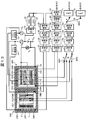
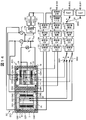
- angular velocity detection part SA1 and SA2 It is a top view of angular velocity detection part SA1 and SA2. It is a block diagram which shows the circuit structure of angular velocity sensor SA. It is a figure which shows the frequency characteristic of two drive vibration systems and detection vibration system of angular velocity detection part SA1 and SA2. It is a figure which shows the circuit structural example which shared the detection circuit by the time division. It is a top view of angular velocity sensor SB in Embodiment 2. It is a block diagram which shows the circuit structure of angular velocity sensor SB. It is a block diagram which shows the top view and circuit structure of angular velocity sensor SC which concern on Embodiment 3. FIG. It is a figure which shows the sideslip axis and rollover axis
- the constituent elements are not necessarily indispensable unless otherwise specified or apparently essential in principle.
- a vibration type angular velocity sensor (hereinafter also simply referred to as “angular velocity sensor”) SA according to Embodiment 1 of the present invention will be described with reference to the drawings.
- angular velocity sensor angular velocity sensor
- a detection unit necessary for detecting an angular velocity necessary for an automobile skidding prevention system and a detection unit necessary for detecting an angular velocity necessary for a rollover detection system are provided.
- a multi-axis multi-range detection angular velocity sensor integrated as one sensor will be described.
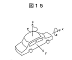
- FIG. 15 is a diagram showing a skid axis and a roll axis of a vehicle.
- the skid prevention system needs information on rotation about an axis (z axis) perpendicular to the ground, and the rollover detection system needs information on rotation about the traveling direction (x axis) of the vehicle.
- the angular velocity sensor used in the skid prevention system is required to have a detection range of ⁇ 100 degrees / second and a resolution of about 1 degree / second in order to detect the side slip of the automobile and control the output of the brake and engine.
- the angular velocity sensor used in the rollover detection system is used only for the judgment of rollover, it is necessary to measure a detection range of ⁇ 400 degrees / second and a resolution of about 4 degrees / second wider than the skid prevention system. .
- the angular velocity sensor SA provides angular velocity information of two detection axes and different detection ranges. By driving these two angular velocity detectors at the same drive frequency, the drive circuit is shared to reduce the cost. A specific method for that will be described later.
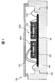
- FIG. 1 is a side sectional view showing the configuration of the angular velocity sensor SA.
- the angular velocity sensor SA includes angular velocity detectors SA1 and SA2.
- the angular velocity detector SA1 detects a side slip of the automobile, and the angular velocity detector SA2 detects a rollover. These detection units are mounted in the ceramic package 150 together with the signal processing IC 50.
- the angular velocity detectors SA1 and SA2 are bonded and fixed on the IC 50. Thereafter, the conductive wire 152 connects the IC 50, the angular velocity detectors SA1 and SA2, and the external input / output terminal 154 of the ceramic package 150 using wire bonding. Finally, sealing with the lid 153 completes the angular velocity sensor SA.
- a plastic package or the like may be used in place of the ceramic package 150 as a package for storing contents such as the angular velocity detectors SA1, SA2 and IC50. That is, any material can be used as long as it can protect the contents such as the conductive wire 152 and can input and output signals with the outside.
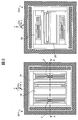
- FIG. 2 is a plan view of the angular velocity detectors SA1 and SA2.
- SA1 and SA2 angular velocity detectors
- the movable part 1A is a part that is driven to vibrate by the drive electrode.
- the movable part 1B is a movable part that is displaced when an angular velocity is generated.
- the fixing portions 7 and 8 are fixed on a support substrate 3 to be described later.
- the angular velocity detection unit SA2 has the same configuration, but here, for convenience of description, only the movable units 2A and 2B are denoted by reference numerals. However, the detection range and detection direction of the angular velocity detection unit SA2 are different from those of the angular velocity detection unit SA1.
- FIG. 3 is a cross-sectional view taken along the line A-A ′ of FIG.
- the cap 100 has a role of protecting the angular velocity detectors SA1 and SA2, and an electrode connected to an external control circuit is formed in the cap 100.
- the support substrate 3 is divided into a silicon substrate 3a, thermal oxide films 3b and 3c, and a space 3d.
- the device layer 4 is a layer in which the movable parts 1A and 1B are formed.
- the electrodes CD1 and CD2 are drive electrodes.
- Electrodes CE1 and CE2 are detection electrodes. Electrodes 9 and 10 are common electrodes.
- Reference numeral 16 denotes a dummy part.
- the groove 25 is formed to separate each part.
- the angular velocity detectors SA1 and SA2 of the angular velocity sensor SA will be described with reference to FIGS. 4 to 7.
- the angular velocity detectors SA1 and SA2 can be formed by the same manufacturing method.
- the description will be made mainly with reference to only the angular velocity detector SA1.
- Each component of the angular velocity detectors SA1 and SA2 is formed by using semiconductor manufacturing technology.
- semiconductor manufacturing technology As a typical semiconductor manufacturing technique used for forming each component, after applying a resist that reacts to light or an electron beam on a substrate, the resist is applied by irradiating light such as ultraviolet rays or an electron beam.
- Photolithography technology that forms a fine pattern by altering and removing the material, and an oxide film or silicon material exposed under the opening of the resist formed by the photolithography technology is alkaline such as hydrofluoric acid or TMAH or KOH.
- Wet etching technology that removes with chemicals, dry etching such as RIE (Reactive Ion Etching) that removes oxide film, silicon, aluminum, etc. exposed in resist openings by using gas and plasma that react with each material There is technology.
- Semiconductor manufacturing techniques including these are used for forming the angular velocity detectors SA1 and SA2 described below.
- FIG. 4 is a diagram showing a method for manufacturing the support substrate 3.
- the support substrate 3 has a role of supporting the fixing portions 7 and 8 of the angular velocity detection unit SA1 described later.
- the support substrate 3 is formed of, for example, a silicon (Si) substrate 3a provided with thermal oxide films 3b and 3c.
- a resist (not shown) is processed to form an opening.
- the oxide film 3b exposed from the opening is removed using a gas or liquid such as hydrofluoric acid.
- the movable portions 1A, 1B, 2A, and 2B move by removing the exposed silicon substrate 3a by using dry etching using RIE, wet etching technology using alkaline chemicals such as TMAH and KOH, and the like.
- the space 3d is formed.
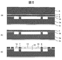
- FIG. 5 is a diagram showing a process of forming each component of the movable parts 1A, 1B, 2A, and 2B and angular velocity detectors SA1 and SA2 described later.
- An SOI (Silicon on Insulator) substrate constituted by the device layer 4, the intermediate insulating layer 5, and the handle layer 6 is bonded to the support substrate 3.
- the support substrate 3 and the SOI substrate are bonded using a hydrogen bonding method in which a hydroxyl group is formed by washing with water. After that, the bonding strength is increased by heating with about 1000 ° C. heat.
- the supporting substrate 3 is made of a glass material, and an anodic bonding method for bonding to an SOI substrate by applying a high voltage, a covalent bonding using a glass frit or a metal adhesive, or the like. And an SOI substrate may be bonded (FIG. 5a).
- the handle layer 6 is removed by a wet etching method using alkaline chemicals or dry etching by RIE, and then the intermediate insulating layer 5 is removed using a hydrofluoric acid (HF) solution.
- HF hydrofluoric acid
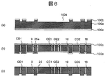
- FIG. 6 is a diagram showing a process for forming the cap 100.
- the cap 100 has a role as an electrode for transmitting an electric signal from the external control circuit 50 to the movable parts 1A and 2A and a function as detection electrodes CE1, CE2, CE3, and CE4 described later.
- a silicon cap substrate 100a provided with oxide films 100b and 100c is prepared, and the movable parts 1A, 1B, 2A, and 2B and the detection electrode CE1, using a photolithography technique and a wet etching technique using DRIE or an alkaline chemical, A gap 100d is formed between CE2, CE3, and CE4 (FIG. 6a).
- the cap substrate 100a is thermally oxidized to form an oxide film 100e on the silicon surface exposed when the gap 100d is formed. Thereafter, the oxide film 100c is processed, and the cap substrate 100a is processed by DRIE until it reaches the oxide film 100e by using it as a mask, so that the electrically independent electrodes CD1, 9, CE1, CE2, 10, CD2, dummy Part 16 is formed. At this time, the oxide film 100e serves as a layer in which DRIE processing is stopped, that is, as an etching stop layer, and by forming the groove 25a by DRIE processing, the respective electrodes CD1, 9 completely separated from the surrounding silicon. , CE1, CE2, 10, CD2, and the dummy portion 16 are also supported (FIG. 6b).
- the thermal oxide film 25 is grown until the groove 25a is completely filled by heating the cap 100 to a high temperature.
- the oxide film 25 is formed by heating silicon at a high temperature, 45% of the oxide film is formed inside the silicon and 55% is formed outside the silicon with the initial silicon surface as a boundary. Further, since it takes an unrealistically long time to form an oxide film of 4 ⁇ m or more on the principle of thermal oxide film growth, the width of the groove 25a is set to 4 ⁇ m. In the DRIE processing, the aspect ratio defined by the width and depth of the groove 25 is 25 or less suitable for mass production. That is, the groove 25 was formed to have a width of 4 ⁇ m and a depth of 100 ⁇ m.
- the thermal oxide films 100b, 100c, and 100e formed on the surface of the cap substrate 100a are removed with a hydrofluoric acid solution (FIG. 6c).
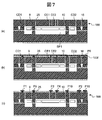
- FIG. 7 is a diagram illustrating a process of bonding the device layer 4 and the support substrate 3 and the cap 100 described with reference to FIG. 5 and a process of forming a metal wiring on the cap 100.
- the cap 100 (FIG. 6c), the device layer 4, and the support substrate 3 (FIG. 5c) can be bonded by the same method as the method of bonding the SOI substrate and the substrate 3 described above (FIG. 7a).
- the pressure in the space SP1 in which the movable parts 1A and 1B are sealed is controlled by controlling the peripheral pressure at the time of joining.
- the pad layer P0 is processed to form pads P1, P2, P3, P4, P9, P10, and P16, thereby completing the angular velocity detectors SA1 and SA2 of the angular velocity sensor SA (FIG. 7c).
- the angular velocity detectors SA1 and SA2 are configured as separate chips, but the angular velocity detectors SA1 and SA2 may be formed on the same chip.
- the angular velocity detectors SA1 and SA2 are manufactured in exactly the same manner, it is obvious that even when two angular velocity detectors SA1 and SA2 are formed on the same support substrate 3, they can be manufactured by the above-described method. It is.
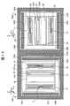
- FIG. 8 is a plan view of the angular velocity detectors SA1 and SA2.
- the detailed configuration of the angular velocity detectors SA1 and SA2 will be described with reference to FIG.
- the movable parts 1A, 2A are suspended from the fixed parts 7, 8, 11, 12 via flexible support beams 21, 22, 23, 24 in the respective driving directions.
- the fixing portions 7, 8, 11, and 12 are formed with a relatively large area, and are fixed to the silicon substrate 3a through the oxide film 3b.
- the movable parts 1B and 2B are suspended from the movable parts 1A and 2A via detection beams 26, 27, 28 and 29.
- an angular velocity is applied to the angular velocity detectors SA1 and SA2 (an acceleration that causes an angular velocity is applied)
- the movable units 1B and 2B are displaced in the detection direction.
- the electrodes CM1, CM2, CM3, and CM4 are monitor electrodes for monitoring the amplitude of the drive electrode.
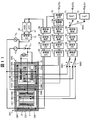
- FIG. 9 is a block diagram showing a circuit configuration of the angular velocity sensor SA. Hereinafter, each functional unit in FIG. 9 will be described.
- the two movable parts 1A, 2A are excited in the respective driving directions by the drive electrodes CD1, CD2, CD3, CD4.
- a drive signal Vcom + Vb + Vd is applied to the drive electrodes CD1 and CD3, and a drive signal Vcom + Vb ⁇ Vd is applied to the drive electrodes CD2 and CD4.
- the movable parts 1A and 2A are connected to Vcom via common electrodes 9, 10, 13, and 14 (here, 13 and 14 are not shown) of the cap 100 connected to the fixed parts 7, 8, 11, and 12. Is applied.
- the potential difference between the drive electrodes CD1, CD2, CD3, CD4 and the movable portions 1A, 2A is Vb ⁇ Vd
- an electrostatic force is generated due to the potential difference
- the two movable portions 1A, 2A vibrate in the respective driving directions. It is configured as follows.
- the movable parts 1A, 2A and the support beams 21, 22, 23, 24 constitute a drive vibration system.
- An AFC (Auto Frequency Control) 51, an AGC (Auto Gain Control) 52, and a DA converter 73 constitute a drive circuit that outputs a drive signal to each drive vibration system.
- a carrier signal Vc which will be described later, is also applied to the fixing portions 7, 8, 11, and 12 through the common electrodes 9, 10, 13, and 14, but the frequency of the carrier signal Vc is several hundred kHz, and the drive vibration
- the carrier signal Vc does not work as a driving force for the driving vibration system because it is sufficiently high that the system cannot follow.
- the drive amplitude generated by applying the drive signal to the movable parts 1A and 2A is to convert the change in capacitance between the drive monitor electrodes CM1, CM2, CM3 and CM4 and the movable parts 1A and 2A into a voltage signal. Can be detected.
- the detection principle will be described with reference to FIG.
- a carrier signal Vc of several hundred kHz is applied to the common electrodes 9, 10, 13, and 14. 2A is propagated, and charge movement is generated according to the capacitance of the drive amplitude monitor electrodes CM1, CM2, CM3, and CM4.
- the CV converters 53 and 57 convert this charge transfer into an analog voltage signal, and the AD converters 54 and 58 further convert this into a digital signal.
- the differential detection units 55 and 59 calculate respective signals. When the drive amplitude is 0, the initial capacitance values cancel each other, so the input voltage to the synchronous detectors 56 and 60 is 0.
- the drive amplitude monitor electrodes CM1 and CM3 increase in capacity following the drive amplitudes of the movable parts 1A and 2A, and the drive amplitude monitor electrodes CM2 and CM4 decrease in capacity. Or vice versa. Therefore, the differential detectors 55 and 59 output signals proportional to the drive amplitude.
- the synchronous detectors 56 and 60 convert the output signal into a drive frequency component (several tens of kHz in the first embodiment) and a low frequency component including DC as required (DC to several hundred Hz in the first embodiment). Convert.
- the angular velocity sensor SA uses an AFC 51 using a PLL (Phase Locked Loop) in order to make the drive frequency ⁇ d follow the change in the natural frequency ⁇ r1 of the drive vibration system of the angular velocity detection unit SA1 due to changes in the surrounding environment (temperature, pressure). It has.
- PLL Phase Locked Loop
- the driving direction of the movable unit 2A is the z-axis direction
- the movable unit 2B is displaced in the y-axis direction, which is the detection direction, by Coriolis force generated by the angular velocity generated around the x-axis.
- the displacements of these movable parts 1B and 2B are the capacitance changes of the detection electrodes CE1 and CE2, CE3 and CE4, respectively, CV conversion parts 61 and 65, AD conversion parts 62 and 66, differential detection parts 63 and 67, and synchronous detection.
- the signals are converted into electrical signals by the units 64 and 68, processed by LPFs (low band pass filters) 71 and 72, and then output.
- LPFs low band pass filters
- the movable parts 1B and 2B and the detection beams 26, 27, 28 and 29 constitute a detection vibration type.
- the CV conversion units 61 and 65, the AD conversion units 62 and 66, the differential detection units 63 and 67, the synchronous detection units 64 and 68, and the LPFs 71 and 72 constitute a detection circuit.
- the skid prevention system only needs to detect an angular velocity component of about several tens of Hz or less, but it is necessary to detect an angular velocity component having a higher frequency in order to detect rollover.
- LPFs 71 and 72 corresponding to the respective angular velocity detection units SA1 and SA2 are provided.
- a correction circuit for correcting the temperature dependence characteristics of the sensor output may be inserted between the switch SW3 and the LPFs 71 and 72.
- the carrier wave Vc leaks to the outside of the angular velocity detection units SA1 and SA2, and signal interference to the peripheral electronic circuit on the system side where the LSI 50 and the angular velocity sensor SA are mounted can be prevented. .
- an effect of blocking the influence of unnecessary high frequency signals from the electronic circuit on the system side and the LSI 50 can be expected.
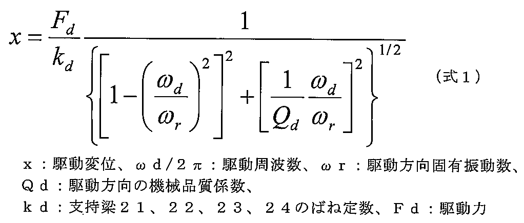
- the following formula 1 is a calculation formula of the driving amplitude x of the angular velocity detection unit
- the following formula 2 is a calculation formula of the Coriolis force Fc
- the following formula 3 is a relational formula between the amplitude in the detection direction and the Coriolis force Fc.
- Equation 1 when the driving force Fd is constant in the driving vibration system composed of the movable parts 1A, 2A and the support beams 21, 22, 23, 24, the driving displacement x depends on the driving frequency ⁇ d / 2 ⁇ .
- the driving frequency ⁇ d / 2 ⁇ When the natural frequency ⁇ r of the drive vibration system and the drive frequency ⁇ d / 2 ⁇ coincide, the largest drive amplitude x is obtained, and the drive amplitude x decreases as the drive frequency ⁇ d / 2 ⁇ moves away from the natural frequency ⁇ r.
- the angular velocity detection unit SA1 has one drive vibration system composed of the movable unit 1A and the support beams 21 and 22.
- the angular velocity detection unit SA2 has one drive vibration system composed of the movable portion 2A and the support beams 23 and 24.
- These drive vibration systems are mechanically arranged so as not to have a path where vibration energy is shared with each other. Since they are separated, each has a natural frequency. That is, the angular velocity sensor SA drives two drive vibration systems having respective natural frequencies at one drive frequency.
- the two drive vibration systems of the angular velocity detectors SA1 and SA2 can adjust their natural frequencies by adjusting the lengths of the support beams 21, 22, 23, and 24.
- the spring constants of the detection beams 26, 27, 28, and 29 are designed to be the same. That is, different drive amplitudes can be obtained from the two drive vibration systems while using the drive circuit and the detection circuit in common.
- the angular velocity sensor SA can obtain two different angular velocity detection results while using a common drive circuit and detection circuit, it is not necessary to provide these circuits for each angular velocity detector, and the cost can be reduced.
- the angular velocity sensor SA according to the first embodiment is configured so that different drive amplitudes can be obtained by adjusting the natural frequencies of the angular velocity detection units SA1 and SA2, while having the drive circuit and the detection circuit in common. Thereby, two different angular velocity detection results are obtained.
- obtaining different drive amplitudes by adjusting the natural frequency will be described in more detail with reference to FIG.
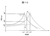
- FIG. 10 is a diagram showing the frequency characteristics of the two drive vibration systems and the detection vibration system of the angular velocity detectors SA1 and SA2.
- f1 is the frequency characteristic of the driving vibration system of the angular velocity detection unit SA1
- f2 is the frequency characteristic of the driving vibration system of the angular velocity detection unit SA2
- f3 is the frequency of the detection vibration system of the angular velocity detection units SA1 and SA2. It is a characteristic.
- “/ 2 ⁇ ” is omitted for each drive frequency for simplicity of description. This is the same in the following description regarding FIG.
- the driving frequency ⁇ d for driving the angular velocity detectors SA1 and SA2 is made to coincide with the natural frequency ⁇ r1 of the driving vibration system of the angular velocity detector SA1, according to Equation 1, the amplitude obtained per unit driving force is
- the driving vibration system of the detection unit SA1 is ga1
- the driving vibration system of the angular velocity detection unit SA2 is ga2.
- the detected amplitude per unit Coriolis force is ga3 in both the angular velocity detectors SA1 and SA2.
- the angular velocity detectors SA1 and SA2 can be used for the purpose of detecting a side slip and a rollover of a car, respectively.
- a side slip it is necessary to detect an angular velocity of ⁇ 100 degrees / second around the z-axis as shown in FIG. It is necessary to detect an angular velocity of ⁇ 400 degrees / second. That is, in order to detect side slip and rollover at the same time, it is necessary to correspond to different detection ranges on different detection axes.
- the Coriolis force Fc converted as the sensor output and the detection amplitude y are It is a function of only the amplitude x. Therefore, the sensitivity of the sensor can be kept constant even when there are fluctuations in the ambient pressure or vibration disturbance. In order to ensure reliability, it is necessary to always monitor the drive amplitude x and perform feedback control to manage it to a constant value. Therefore, the angular velocity sensor SA inputs the drive amplitude of either the angular velocity detector SA1 or SA2 to the AGC 52, and performs feedback control so as to follow a preset target value. The output from the AGC 52 is converted into an analog signal by the DA converter 73 and applied to the drive electrodes CD1, CD2, CD3, CD4.
- the drive amplitude of the side slip detection unit (angular velocity detection unit SA1), which requires higher accuracy, should be input to the AGC 52 for feedback control. That is, the greater the drive amplitude, the greater the sensitivity as a sensor. Therefore, the drive frequency ⁇ d is set in accordance with the natural frequency ⁇ r1 of the angular velocity detector SA1 having the narrowest detection range so that the largest displacement can be obtained. desirable.
- the drive circuit can be made common to the angular velocity detectors SA1 and SA2.
- a method for making the detection circuit common to the angular velocity detection units SA1 and SA2 will be described.
- the Coriolis force Fc generated when the maximum angular velocity of each range occurs is set to the same value for each of the angular velocity detectors SA1 and SA2, and the detection electrode CE1. , CE2, CE3, and CE4 must have the same capacitance change characteristics. However, when the servo control described above is used, only the Coriolis force Fc may be made the same between the angular velocity detection units.
- the Coriolis force Fc is proportional to the drive amplitude x. Therefore, in order to generate the same Coriolis force Fc in each of the detection ranges in which the angular velocity detection units SA1 and SA2 are different, the relationship of the following formula 4 needs to be established between the detection range and the drive amplitude.
- the drive amplitude 1 (ga1) is set to 4 ⁇ m. It will be. Further, it can be used as a means for confirming whether or not the sensor is operating normally by checking whether or not these two drive amplitudes comply with the relationship of Expression 4.
- the gain adjustment unit 69 in FIG. 9 processes the drive amplitude of the angular velocity detection unit SA2 based on the relational expression of Expression 4.
- the self-diagnosis unit 70 compares the output from the gain adjustment unit 69 with the drive amplitude of the angular velocity detection unit SA1 (output from the synchronous detection unit 56), and determines whether or not it is within the specified range. The result is output as a diagnosis result (output 3).
- FIG. 11 is a diagram illustrating a circuit configuration example in which the detection circuit is shared in a time division manner.
- the maximum capacitance change amounts of the detection electrodes CE1, CE2, CE3, and CE4 of the two detection units SA1 and SA2 are the same. Therefore, the CV converters 61 and 65, the AD converters 62 and 66, the differential detectors 63 and 67, and the synchronous detectors 64 and 68 can be shared in a time division manner.
- the switches SW1 and SW2 select the inputs from the angular velocity detectors SA1 and SA2, and the switch SW3 switches the LPFs 71 and 72. The three switches are synchronized with each other and are switched at the same timing.
- a configuration in which the detection circuit is shared in a time-sharing manner as in FIG. 11 can also be employed in the following embodiments.
- the angular velocity sensor SA includes a plurality of angular velocity detectors having different natural frequencies of the drive vibration system, and the drive frequency of the drive signal that drives each angular velocity detector is common. .
- the drive frequency can be matched to any natural frequency.
- one of the angular velocity detection units is driven in the resonance mode, and the remaining angular velocity detection units are driven in the non-resonance mode. Since the angular velocity detection unit driven in the resonance mode can obtain a larger driving amplitude than the angular velocity detection unit driven in the non-resonance mode, an output signal larger than that of the other angular velocity detection unit can be generated for the same angular velocity. .
- a plurality of angular velocity detectors having different detection ranges defined as the applied angular velocity and the magnitude of the generated signal can be realized by the same drive frequency output from the common drive circuit.
- the angular velocity sensor SA according to the first embodiment is configured such that the angular velocity detectors SA1 and SA2 having different detection ranges generate the same Coriolis force Fc according to the relationship of Expression 4. Thereby, the detection signal which each angular velocity detection part SA1 and SA2 outputs can be processed using the detection circuit of the same specification.
- the angular velocity sensor SA can detect angular velocities in different detection directions by making the arrangement directions of the respective angular velocity detectors different from each other. Thereby, an angular velocity sensor having a plurality of different detection directions can be provided by using the detection circuit having the same specification.
- the angular velocity sensor SA is a non-tuning fork type configured as one movable portion 1A and 1B and support beams 21, 22, 23, and 24 flexible in each driving direction with respect to each driving direction.
- the drive vibration system was illustrated.
- the structure which concerns on this invention is not restricted to this, By arrange
- the present invention can also be applied to a configuration having a tuning fork structure.
- at least one of the angular velocity detectors SA1 and SA2 is configured as a tuning fork type angular velocity sensor.
- the effect of adopting the tuning fork structure is well known and will not be described in detail, but it should be clarified that the angular velocity sensor SA according to the first embodiment is not limited to the non-tuning fork structure.
- the AFC 51 is provided in order to make the drive frequency ⁇ d follow the change in the natural frequency ⁇ r1.
- the present invention is not limited to this as long as different drive amplitudes can be obtained using the same drive frequency. That is, it goes without saying that the concept of the present invention can be applied to non-resonant mode driving in which the driving frequency ⁇ d and the natural frequency ⁇ r1 are not matched.
- the drive electrodes CD1, CD2, CD3, CD4 and the monitor electrodes CM1, CM2, CM3, CM4 of the angular velocity detectors SA1, SA2 are shown in a parallel plate structure for convenience, but the flat plates are staggered.
- a comb-shaped structure engaged with each other may be adopted.
- the example in which the detection results of the respective angular velocity detection units are output in parallel as outputs 1 and 2 has been described, but a single output terminal may be used. In this case, a plurality of detection results are output as serial signals.
- FIG. 12 is a plan view of the angular velocity sensor SB according to the second embodiment.
- the manufacturing method of the angular velocity sensor SB is the same as that of the angular velocity sensor SA in the first embodiment.
- the angular velocity detectors SB1 and SB2 having exactly the same shape are arranged and driven with different driving voltages, thereby generating different driving amplitudes and obtaining different detection results. . That is, in the first embodiment, the natural frequencies ⁇ r1 and ⁇ r2 are set to different values by adjusting the lengths of the support beams 21, 22, 23, and 24.
- the angular velocity sensor SB of the second embodiment has the same angular velocity.
- the detectors SB1 and SB2 are arranged by changing only their directions in accordance with the axis of the angular velocity to be detected.
- the Coriolis force Fc and detection amplitude y converted as the sensor output are It is a function of only the drive amplitude x.
- the driving amplitude x is a function of the driving force Fd.
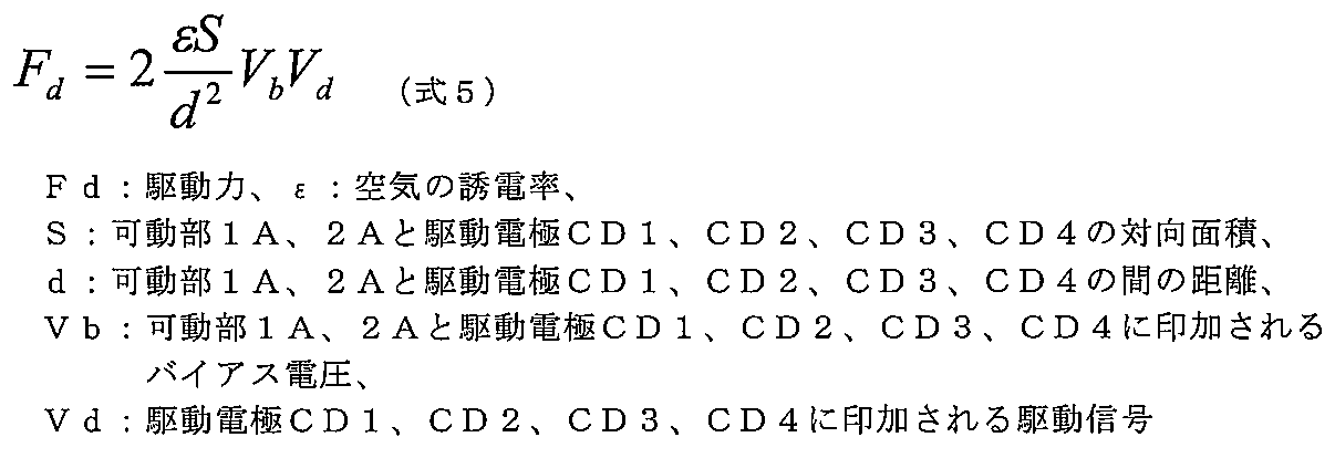
- the driving force Fd generated between the movable parts 1A, 2A and the driving electrodes CD1, CD2, CD3, CD4 can be defined by the following equation (5).
- the driving force Fd is proportional to the driving signal Vd. That is, since the driving amplitude x is proportional to the driving force Fd, and the driving force Fd is proportional to the driving signal Vd, the driving amplitude x can be controlled by controlling the driving signal Vd.
- the angular velocity sensor SB according to the second embodiment uses this fact to realize the drive amplitude that satisfies the condition of Expression 4.
- FIG. 13 is a block diagram showing a circuit configuration of the angular velocity sensor SB.
- the angular velocity sensor SB includes gain adjustment units 74 and 75 in addition to the circuit configuration described in the first embodiment. Although the circuit configuration similar to that of FIG. 11 is illustrated here, the circuit configuration of FIG. 9 may be employed.
- the gain adjusters 74 and 75 adjust the signal level of the drive signal Vd applied to the angular velocity detectors SB1 and SB2, respectively. Thereby, while using exactly the same angular velocity detectors SB1 and SB2, different drive amplitudes can be generated and different detection ranges can be provided.
- the drive frequency ⁇ d in accordance with the natural frequency of the angular velocity detector having the narrowest detection range so that the largest displacement can be obtained.
- the drive signals having the same frequency and different signal levels are applied to each angular velocity detection unit, and the drive amplitude of each angular velocity detection unit is the signal of the applied drive signal. Different levels with different levels of correlation. Therefore, as in the first embodiment, a plurality of angular velocity detectors having different detection ranges defined as applied angular velocities and generated signal magnitudes are realized by the same drive frequency output by a common drive circuit. be able to.
- the angular velocity detectors SB1 and SB2 are formed on the single support substrate 3, but may be divided into two chips. By changing the orientation of two identical chips at the time of mounting, the manufacturing yield can be improved. That is, when the two angular velocity detectors SB1 and SB2 are configured as one chip, both cannot be used even if a defect occurs on one side, but the chip is effectively utilized by adopting a two-chip configuration. be able to.
- the two identical angular velocity detectors SB1 and SB2 are used. Strictly speaking, it is possible to realize two angular velocity detectors having exactly the same natural frequency due to variations in manufacturing. It seems difficult. However, if the two natural frequencies are close to each other within a certain range, the variation in performance can be ignored, and the gain adjusting units 74 and 75 can correct the manufacturing variation.
- FIG. 14 is a block diagram showing a plan view and a circuit configuration of the angular velocity sensor SC according to the third embodiment.
- the manufacturing method of the angular velocity sensor SC is the same as that of the angular velocity sensors SA and SB in the first and second embodiments.
- the size and electrode interval of the drive electrodes of the angular velocity detectors SC1 and SC2 are different from each other.
- the angular velocity sensor SC includes an area S of a portion where the drive electrodes CD1, CD2, CD3, CD4 and the movable parts 1A, 2A are opposed to each other and a gap d between the drive electrodes CD1 to CD4 and the movable parts 1A, 2A shown in Expression 5.
- the angular velocity detectors SC1 and SC2 generate different driving forces Fd and driving amplitudes x.
- the angular velocity sensor SC includes the two angular velocity detectors SC1 and SC2 having different facing areas S or gaps d between the drive electrodes CD1 to CD4 and the movable portions 1A and 2A.
- a plurality of angular velocity detectors having different detection ranges defined as applied angular velocities and generated signal magnitudes are realized by the same drive frequency output by a common drive circuit. can do.
- the support beams 21 and 22 and the support beams 23 and 24 have the same spring constant k and the weights of the movable parts 1A and 2A are the same, the natural frequencies ⁇ r1 and ⁇ r2 of the two vibration systems. Is the same. Strictly speaking, however, it seems difficult to realize two angular velocity detectors having exactly the same natural frequency due to manufacturing variations and the like. However, if the two natural frequencies are close to each other within a certain range, the variation in performance can be ignored, and the gain adjusting units 74 and 75 described in the second embodiment are provided to reduce the manufacturing variation. It can also be corrected.
- the angular velocity detectors SC1 and SC2 are formed on one support substrate 3.
- the angular velocity detectors SC1 and SC2 may be divided into two chips. By changing only the orientation of two chips when mounted, angular velocity information of different detection axes can be obtained. If arranged in the same direction, angular velocity information with different detection ranges of the corresponding detection axes can be obtained.
- the present invention is not limited to this application.
- it can be widely used in fields such as robot posture detection, car navigation, digital camera shake correction, navigation posture / direction detection, and game machine posture detection sensors.
- it can be expected to exert its power when it is necessary to detect angular velocities of a plurality of detection axes or a plurality of detection ranges.
- SA angular velocity sensor
- SB angular velocity sensor
- SA1 to SA2 angular velocity detector
- SB1 to SB2 angular velocity detector
- SP1 space
- SW1 to SW3 switch
- CD1 to CD4 drive electrode
- CM1 to CM4 monitor electrode ( Drive amplitude monitor electrode)
- CE1 to CE4 detection electrode
- Vc carrier wave (carrier signal)
- 1B movable portion
- 2A movable portion
- 2B movable portion
- 3 support substrate
- 3a silicon substrate
- 3b Thermal oxide film
- 3c Thermal oxide film
- 3d Space
- 4 Device layer
- 5 Intermediate insulating layer
- 6 Handle layer
- 7-8 Fixed part
- 9-10 Common electrode
- 11-12 Fixing part
- 16 Dummy part
- 21-24 Support beam
- 25 Insulating film
- 25a: Groove, 26-29 Detection beam
- 50: IC IC
- 51: AFC 52: AGC
Landscapes
- Engineering & Computer Science (AREA)
- Physics & Mathematics (AREA)
- General Physics & Mathematics (AREA)
- Radar, Positioning & Navigation (AREA)
- Remote Sensing (AREA)
- Signal Processing (AREA)
- Gyroscopes (AREA)
- Pressure Sensors (AREA)
- Micromachines (AREA)
Abstract
Description
本発明の実施形態1に係る振動型角速度センサ(以下、単に「角速度センサ」ともいう)SAについて図面を参照しながら説明する。本実施形態1では、具体的な応用例として、自動車の横滑り防止システムに必要な角速度を検知するために必要な検知部と横転検知システムに必要な角速度を検知するために必要な検知部を1つのセンサとして一体化した多軸マルチレンジ検知角速度センサについて説明する。
図1は、角速度センサSAの構成を示す側断面図である。角速度センサSAは、角速度検知部SA1とSA2を備える。角速度検知部SA1は自動車の横滑りを検知し、角速度検知部SA2は横転を検知する。これら検知部は、セラミックパッケージ150内に信号処理用のIC50とともに実装される。
図8は、角速度検知部SA1、SA2の平面図である。以下、角速度検知部SA1、SA2の詳細構成について、図8を参照しながら説明する。
以上、角速度センサSAの動作原理について説明した。以下では、2つの異なる検出レンジを有する角速度検知部SA1とSA2を同一周波数の駆動信号によって駆動することについて、その原理を説明する。



以上のように、本実施形態1に係る角速度センサSAは、駆動振動系の固有振動数がそれぞれ異なる複数の角速度検知部を備え、各角速度検知部を駆動する駆動信号の駆動周波数は共通である。駆動周波数は、いずれかの固有振動数に合わせることができる。この場合、いずれかの角速度検知部は共振モードで駆動され、残りの角速度検知部は非共振モードで駆動される。共振モードで駆動される角速度検知部は非共振モードで駆動される角速度検知部より大きい駆動振幅が得られるため、同じ角速度に対して他方の角速度検知部よりも大きい出力信号を生成することができる。その結果、印加される角速度と発生する信号の大きさとして定義される検出レンジが互いに異なる複数の角速度検知部を、共通の駆動回路が出力する同一の駆動周波数によって実現することができる。
実施形態1では、駆動振動系の固有振動数がそれぞれ異なることを利用して、同一周波数の駆動信号により異なる駆動振幅を生じさせることを説明した。本発明の実施形態2では、各角速度検知部に印加する駆動信号の信号レベルをそれぞれ変えることにより、異なる駆動振幅を生じさせる構成例を説明する。以下では、実施形態1と共通する点については説明を省略し、差異点を中心に説明する。
以上のように、本実施形態2に係る角速度センサSBにおいて、各角速度検知部には同一周波数で信号レベルが異なる駆動信号が印加され、各角速度検知部の駆動振幅は印加される駆動信号の信号レベルに相関を持ってそれぞれ異なる値となる。したがって、実施形態1と同様に、印加される角速度と発生する信号の大きさとして定義される検出レンジが互いに異なる複数の角速度検知部を、共通の駆動回路が出力する同一の駆動周波数によって実現することができる。
本発明の実施形態3では、駆動電極CD1~CD4と可動部1Aおよび2Aが形成する静電容量を角速度検知部毎に変えることにより、異なる駆動振幅を生じさせる構成例を説明する。以下では、実施形態1と共通する点については説明を省略し、差異点を中心に説明する。
以上のように、本実施形態3に係る角速度センサSCは、駆動電極CD1~CD4と可動部1A、2A間の対向面積Sまたはギャップdが異なる2つの角速度検知部SC1、SC2を備える。これにより、実施形態1と同様に、印加される角速度と発生する信号の大きさとして定義される検出レンジが互いに異なる複数の角速度検知部を、共通の駆動回路が出力する同一の駆動周波数によって実現することができる。
Claims (13)
- 角速度を検知する複数の角速度検知部と、
前記複数の角速度検知部を同一周波数の駆動信号によって駆動する駆動回路と、
各前記角速度検知部の検知結果を出力する検出回路と、
を備え、
各前記角速度検知部は、前記駆動信号によって駆動されたときの駆動振幅がそれぞれ異なるように構成されており、
前記検出回路は、各前記駆動振幅にそれぞれ対応する、各前記角速度検知部の前記検知結果を出力する
ことを特徴とする角速度センサ。 - 請求項1において、
各前記角速度検知部は、前記駆動信号によって前記駆動振幅で振動する駆動振動系を備え、
各前記角速度検知部が備える前記駆動振動系は、前記駆動振幅による振動エネルギーを互いに共有しないように構成されている
ことを特徴とする角速度センサ。 - 請求項2において、
各前記角速度検知部が備える前記駆動振動系は、
固有振動数が互いに異なることにより、前記駆動信号によって駆動されたときの駆動振幅がそれぞれ異なるように構成されている
ことを特徴とする角速度センサ。 - 請求項3において、
各前記角速度検知部は、それぞれ異なる検出レンジを有し、
前記駆動回路は、
前記駆動周波数を、各前記角速度検知部のうち最も検出レンジが狭いものが備える前記駆動振動系の前記固有振動数に追従させる
ことを特徴とする角速度センサ。 - 請求項3において、
各前記角速度検知部は、
それぞれ異なる検出レンジを有し、かつ前記駆動振動系が生じさせるコリオリ力が互いに等しくなるように構成されている
ことを特徴とする角速度センサ。 - 請求項5において、
各前記角速度検知部は、
前記駆動振動系の前記駆動振幅同士の比を、各前記角速度検知部の検出レンジ同士の比の逆数となるように構成することにより、前記駆動振動系が生じさせるコリオリ力が互いに等しくなるように構成されている
ことを特徴とする角速度センサ。 - 請求項1において、
各前記角速度検知部は、検出した前記角速度に対応する検出信号を出力する検出振動系をそれぞれ備え、
前記検出回路は、前記検出信号を処理して前記検出結果として出力し、
各前記角速度検知部は、前記検出回路を時分割で共有する
ことを特徴とする角速度センサ。 - 請求項2において、
前記駆動回路は、
それぞれ異なる信号レベルの前記駆動信号を用いて各前記角速度検知部を駆動することにより、各前記角速度検知部が前記駆動信号によって駆動されたときの駆動振幅がそれぞれ異なるようにする
ことを特徴とする角速度センサ。 - 請求項8において、
各前記角速度検知部は、それぞれ異なる検出レンジを有し、
前記駆動回路は、各前記角速度検知部のうち最も検出レンジが狭いものを、最も信号レベルが大きい前記駆動信号によって駆動する
ことを特徴とする角速度センサ。 - 請求項2において、
各前記角速度検知部は、
前記駆動信号によって駆動される駆動電極が形成する静電容量がそれぞれ異なることにより、前記駆動信号によって駆動されたときの駆動振幅がそれぞれ異なるように構成されている
ことを特徴とする角速度センサ。 - 請求項10において、
各前記角速度検知部は、前記駆動電極と対向して前記静電容量を形成する部位の面積がそれぞれ異なることにより、前記静電容量がそれぞれ異なるように構成されている
ことを特徴とする角速度センサ。 - 請求項10において、
各前記角速度検知部は、前記駆動電極と対向して前記静電容量を形成する部位と前記駆動電極との間の間隔がそれぞれ異なることにより、前記静電容量がそれぞれ異なるように構成されている
ことを特徴とする角速度センサ。 - 請求項1において、
各前記角速度検知部は検知軸がそれぞれ異なることを特徴とする角速度センサ。
Priority Applications (4)
| Application Number | Priority Date | Filing Date | Title |
|---|---|---|---|
| US14/383,335 US9568490B2 (en) | 2012-03-19 | 2012-03-19 | Angular velocity sensor |
| JP2014505822A JP5889396B2 (ja) | 2012-03-19 | 2012-03-19 | 角速度センサ |
| PCT/JP2012/056978 WO2013140488A1 (ja) | 2012-03-19 | 2012-03-19 | 角速度センサ |
| DE112012006056.3T DE112012006056T5 (de) | 2012-03-19 | 2012-03-19 | Winkelgeschwindigkeitssensor |
Applications Claiming Priority (1)
| Application Number | Priority Date | Filing Date | Title |
|---|---|---|---|
| PCT/JP2012/056978 WO2013140488A1 (ja) | 2012-03-19 | 2012-03-19 | 角速度センサ |
Publications (1)
| Publication Number | Publication Date |
|---|---|
| WO2013140488A1 true WO2013140488A1 (ja) | 2013-09-26 |
Family
ID=49221984
Family Applications (1)
| Application Number | Title | Priority Date | Filing Date |
|---|---|---|---|
| PCT/JP2012/056978 Ceased WO2013140488A1 (ja) | 2012-03-19 | 2012-03-19 | 角速度センサ |
Country Status (4)
| Country | Link |
|---|---|
| US (1) | US9568490B2 (ja) |
| JP (1) | JP5889396B2 (ja) |
| DE (1) | DE112012006056T5 (ja) |
| WO (1) | WO2013140488A1 (ja) |
Cited By (2)
| Publication number | Priority date | Publication date | Assignee | Title |
|---|---|---|---|---|
| EP2913680A1 (en) * | 2014-02-28 | 2015-09-02 | Seiko Epson Corporation | Electronic device, electronic apparatus, and moving object |
| WO2022004375A1 (ja) * | 2020-06-30 | 2022-01-06 | ソニーグループ株式会社 | 駆動制御装置、および駆動制御方法 |
Families Citing this family (2)
| Publication number | Priority date | Publication date | Assignee | Title |
|---|---|---|---|---|
| JP6571064B2 (ja) * | 2016-11-21 | 2019-09-04 | 株式会社東芝 | 検出装置およびセンサ装置 |
| DE102017213637A1 (de) | 2017-08-07 | 2019-02-07 | Robert Bosch Gmbh | Ein- und zweiachsiger Drehratensensor |
Citations (5)
| Publication number | Priority date | Publication date | Assignee | Title |
|---|---|---|---|---|
| JPH0719878A (ja) * | 1993-06-30 | 1995-01-20 | Murata Mfg Co Ltd | 振動ジャイロ |
| JPH09210691A (ja) * | 1996-02-01 | 1997-08-12 | Tokin Corp | 圧電振動ジャイロ |
| JP2004309476A (ja) * | 2003-03-27 | 2004-11-04 | Denso Corp | 振動型マイクロジャイロセンサ |
| JP2006267094A (ja) * | 2005-02-25 | 2006-10-05 | Kyocera Kinseki Corp | 慣性センサ素子 |
| JP2010002361A (ja) * | 2008-06-23 | 2010-01-07 | Murata Mfg Co Ltd | 振動ジャイロ |
Family Cites Families (14)
| Publication number | Priority date | Publication date | Assignee | Title |
|---|---|---|---|---|
| US6705151B2 (en) * | 1995-05-30 | 2004-03-16 | Matsushita Electric Industrial Co., Ltd. | Angular velocity sensor |
| US5911156A (en) * | 1997-02-24 | 1999-06-08 | The Charles Stark Draper Laboratory, Inc. | Split electrode to minimize charge transients, motor amplitude mismatch errors, and sensitivity to vertical translation in tuning fork gyros and other devices |
| US6338199B1 (en) | 1997-03-25 | 2002-01-15 | Canon Kabushiki Kaisha | Sensor |
| JPH10267664A (ja) | 1997-03-25 | 1998-10-09 | Canon Inc | センサ |
| JP4004129B2 (ja) * | 1998-02-09 | 2007-11-07 | マイクロストーン株式会社 | 運動センサ |
| US6666091B2 (en) * | 2000-08-30 | 2003-12-23 | Matsushita Electric Industrial Co., Ltd. | Angular velocity sensor |
| US6701788B2 (en) | 2001-07-31 | 2004-03-09 | Kelsey-Hayes Company | Multiple output inertial sensing device |
| US6993969B2 (en) | 2003-03-27 | 2006-02-07 | Denso Corporation | Vibration type of micro gyro sensor |
| US7383729B2 (en) * | 2006-10-12 | 2008-06-10 | Honeywell International, Inc. | Tuning fork gyro with sense plate read-out |
| US20080098814A1 (en) | 2006-10-31 | 2008-05-01 | Honeywell International Inc. | Dual mode mems sensor |
| JP2010060361A (ja) * | 2008-09-02 | 2010-03-18 | Murata Mfg Co Ltd | 音叉型振動子、音叉型振動子の製造方法および角速度センサ |
| WO2010051560A1 (en) * | 2008-11-03 | 2010-05-06 | Georgia Tech Research Corporation | Vibratory gyroscope utilizing a frequency-based measurement and providing a frequency output |
| US8322213B2 (en) * | 2009-06-12 | 2012-12-04 | The Regents Of The University Of California | Micromachined tuning fork gyroscopes with ultra-high sensitivity and shock rejection |
| DE102012210144A1 (de) * | 2012-06-15 | 2013-12-19 | Robert Bosch Gmbh | Verfahren zum Betrieb und/oder zur Vermessung einer mikromechanischen Vorrichtung und mikromechanische Vorrichtung |
-
2012
- 2012-03-19 JP JP2014505822A patent/JP5889396B2/ja not_active Expired - Fee Related
- 2012-03-19 US US14/383,335 patent/US9568490B2/en not_active Expired - Fee Related
- 2012-03-19 WO PCT/JP2012/056978 patent/WO2013140488A1/ja not_active Ceased
- 2012-03-19 DE DE112012006056.3T patent/DE112012006056T5/de not_active Withdrawn
Patent Citations (5)
| Publication number | Priority date | Publication date | Assignee | Title |
|---|---|---|---|---|
| JPH0719878A (ja) * | 1993-06-30 | 1995-01-20 | Murata Mfg Co Ltd | 振動ジャイロ |
| JPH09210691A (ja) * | 1996-02-01 | 1997-08-12 | Tokin Corp | 圧電振動ジャイロ |
| JP2004309476A (ja) * | 2003-03-27 | 2004-11-04 | Denso Corp | 振動型マイクロジャイロセンサ |
| JP2006267094A (ja) * | 2005-02-25 | 2006-10-05 | Kyocera Kinseki Corp | 慣性センサ素子 |
| JP2010002361A (ja) * | 2008-06-23 | 2010-01-07 | Murata Mfg Co Ltd | 振動ジャイロ |
Cited By (3)
| Publication number | Priority date | Publication date | Assignee | Title |
|---|---|---|---|---|
| EP2913680A1 (en) * | 2014-02-28 | 2015-09-02 | Seiko Epson Corporation | Electronic device, electronic apparatus, and moving object |
| JP2015161640A (ja) * | 2014-02-28 | 2015-09-07 | セイコーエプソン株式会社 | 電子デバイス、電子機器、および移動体 |
| WO2022004375A1 (ja) * | 2020-06-30 | 2022-01-06 | ソニーグループ株式会社 | 駆動制御装置、および駆動制御方法 |
Also Published As
| Publication number | Publication date |
|---|---|
| JP5889396B2 (ja) | 2016-03-22 |
| US20150096373A1 (en) | 2015-04-09 |
| JPWO2013140488A1 (ja) | 2015-08-03 |
| US9568490B2 (en) | 2017-02-14 |
| DE112012006056T5 (de) | 2014-12-18 |
Similar Documents
| Publication | Publication Date | Title |
|---|---|---|
| JP5444199B2 (ja) | 複合センサ | |
| US5461916A (en) | Mechanical force sensing semiconductor device | |
| US7513155B2 (en) | Inertial sensor | |
| US9182421B2 (en) | Inertia sensor | |
| US20070240509A1 (en) | Dynamic amount sensor | |
| US20050217375A1 (en) | Sensor system | |
| US20100127715A1 (en) | Semiconductor physical quantity sensor and control device using the same | |
| US20120291546A1 (en) | Inertial sensor | |
| JP6972845B2 (ja) | 物理量測定装置、電子機器及び移動体 | |
| JP5301767B2 (ja) | 慣性センサ | |
| US9511993B2 (en) | Semiconductor physical quantity detecting sensor | |
| EP3335004B1 (en) | Angular velocity sensors | |
| JP5889396B2 (ja) | 角速度センサ | |
| US20130047726A1 (en) | Angular rate sensor with different gap sizes | |
| JP4362877B2 (ja) | 角速度センサ | |
| JP3780673B2 (ja) | 角速度センサ | |
| JP6125914B2 (ja) | 角速度センサ | |
| JP3449130B2 (ja) | 力学量センサおよびそれを用いた集積回路 | |
| JP6285128B2 (ja) | 角速度センサ | |
| JP4362739B2 (ja) | 振動型角速度センサ |
Legal Events
| Date | Code | Title | Description |
|---|---|---|---|
| 121 | Ep: the epo has been informed by wipo that ep was designated in this application |
Ref document number: 12872036 Country of ref document: EP Kind code of ref document: A1 |
|
| ENP | Entry into the national phase |
Ref document number: 2014505822 Country of ref document: JP Kind code of ref document: A |
|
| WWE | Wipo information: entry into national phase |
Ref document number: 1120120060563 Country of ref document: DE Ref document number: 112012006056 Country of ref document: DE |
|
| WWE | Wipo information: entry into national phase |
Ref document number: 14383335 Country of ref document: US |
|
| 122 | Ep: pct application non-entry in european phase |
Ref document number: 12872036 Country of ref document: EP Kind code of ref document: A1 |