WO2013137232A1 - 電気自動車の充電装置及び充電システム - Google Patents
電気自動車の充電装置及び充電システム Download PDFInfo
- Publication number
- WO2013137232A1 WO2013137232A1 PCT/JP2013/056750 JP2013056750W WO2013137232A1 WO 2013137232 A1 WO2013137232 A1 WO 2013137232A1 JP 2013056750 W JP2013056750 W JP 2013056750W WO 2013137232 A1 WO2013137232 A1 WO 2013137232A1
- Authority
- WO
- WIPO (PCT)
- Prior art keywords
- charging device
- charging
- secondary battery
- built
- electric
- Prior art date
- Legal status (The legal status is an assumption and is not a legal conclusion. Google has not performed a legal analysis and makes no representation as to the accuracy of the status listed.)
- Ceased
Links
Images


Classifications
-
- H—ELECTRICITY
- H02—GENERATION; CONVERSION OR DISTRIBUTION OF ELECTRIC POWER
- H02J—ELECTRIC POWER NETWORKS; CIRCUIT ARRANGEMENTS OR SYSTEMS FOR SUPPLYING OR DISTRIBUTING ELECTRIC POWER; SYSTEMS FOR STORING ELECTRIC ENERGY
- H02J7/00—Circuit arrangements for charging or discharging batteries or for supplying loads from batteries
- H02J7/34—Parallel operation in networks using both storage and other DC sources, e.g. providing buffering
-
- B—PERFORMING OPERATIONS; TRANSPORTING
- B60—VEHICLES IN GENERAL
- B60L—PROPULSION OF ELECTRICALLY-PROPELLED VEHICLES; SUPPLYING ELECTRIC POWER FOR AUXILIARY EQUIPMENT OF ELECTRICALLY-PROPELLED VEHICLES; ELECTRODYNAMIC BRAKE SYSTEMS FOR VEHICLES IN GENERAL; MAGNETIC SUSPENSION OR LEVITATION FOR VEHICLES; MONITORING OPERATING VARIABLES OF ELECTRICALLY-PROPELLED VEHICLES; ELECTRIC SAFETY DEVICES FOR ELECTRICALLY-PROPELLED VEHICLES
- B60L53/00—Methods of charging batteries, specially adapted for electric vehicles; Charging stations or on-board charging equipment therefor; Exchange of energy storage elements in electric vehicles
- B60L53/10—Methods of charging batteries, specially adapted for electric vehicles; Charging stations or on-board charging equipment therefor; Exchange of energy storage elements in electric vehicles characterised by the energy transfer between the charging station and the vehicle
- B60L53/11—DC charging controlled by the charging station, e.g. mode 4
-
- B—PERFORMING OPERATIONS; TRANSPORTING
- B60—VEHICLES IN GENERAL
- B60L—PROPULSION OF ELECTRICALLY-PROPELLED VEHICLES; SUPPLYING ELECTRIC POWER FOR AUXILIARY EQUIPMENT OF ELECTRICALLY-PROPELLED VEHICLES; ELECTRODYNAMIC BRAKE SYSTEMS FOR VEHICLES IN GENERAL; MAGNETIC SUSPENSION OR LEVITATION FOR VEHICLES; MONITORING OPERATING VARIABLES OF ELECTRICALLY-PROPELLED VEHICLES; ELECTRIC SAFETY DEVICES FOR ELECTRICALLY-PROPELLED VEHICLES
- B60L53/00—Methods of charging batteries, specially adapted for electric vehicles; Charging stations or on-board charging equipment therefor; Exchange of energy storage elements in electric vehicles
- B60L53/10—Methods of charging batteries, specially adapted for electric vehicles; Charging stations or on-board charging equipment therefor; Exchange of energy storage elements in electric vehicles characterised by the energy transfer between the charging station and the vehicle
- B60L53/14—Conductive energy transfer
-
- B—PERFORMING OPERATIONS; TRANSPORTING
- B60—VEHICLES IN GENERAL
- B60L—PROPULSION OF ELECTRICALLY-PROPELLED VEHICLES; SUPPLYING ELECTRIC POWER FOR AUXILIARY EQUIPMENT OF ELECTRICALLY-PROPELLED VEHICLES; ELECTRODYNAMIC BRAKE SYSTEMS FOR VEHICLES IN GENERAL; MAGNETIC SUSPENSION OR LEVITATION FOR VEHICLES; MONITORING OPERATING VARIABLES OF ELECTRICALLY-PROPELLED VEHICLES; ELECTRIC SAFETY DEVICES FOR ELECTRICALLY-PROPELLED VEHICLES
- B60L53/00—Methods of charging batteries, specially adapted for electric vehicles; Charging stations or on-board charging equipment therefor; Exchange of energy storage elements in electric vehicles
- B60L53/30—Constructional details of charging stations
- B60L53/31—Charging columns specially adapted for electric vehicles
-
- B—PERFORMING OPERATIONS; TRANSPORTING
- B60—VEHICLES IN GENERAL
- B60L—PROPULSION OF ELECTRICALLY-PROPELLED VEHICLES; SUPPLYING ELECTRIC POWER FOR AUXILIARY EQUIPMENT OF ELECTRICALLY-PROPELLED VEHICLES; ELECTRODYNAMIC BRAKE SYSTEMS FOR VEHICLES IN GENERAL; MAGNETIC SUSPENSION OR LEVITATION FOR VEHICLES; MONITORING OPERATING VARIABLES OF ELECTRICALLY-PROPELLED VEHICLES; ELECTRIC SAFETY DEVICES FOR ELECTRICALLY-PROPELLED VEHICLES
- B60L53/00—Methods of charging batteries, specially adapted for electric vehicles; Charging stations or on-board charging equipment therefor; Exchange of energy storage elements in electric vehicles
- B60L53/50—Charging stations characterised by energy-storage or power-generation means
- B60L53/53—Batteries
-
- B—PERFORMING OPERATIONS; TRANSPORTING
- B60—VEHICLES IN GENERAL
- B60L—PROPULSION OF ELECTRICALLY-PROPELLED VEHICLES; SUPPLYING ELECTRIC POWER FOR AUXILIARY EQUIPMENT OF ELECTRICALLY-PROPELLED VEHICLES; ELECTRODYNAMIC BRAKE SYSTEMS FOR VEHICLES IN GENERAL; MAGNETIC SUSPENSION OR LEVITATION FOR VEHICLES; MONITORING OPERATING VARIABLES OF ELECTRICALLY-PROPELLED VEHICLES; ELECTRIC SAFETY DEVICES FOR ELECTRICALLY-PROPELLED VEHICLES
- B60L53/00—Methods of charging batteries, specially adapted for electric vehicles; Charging stations or on-board charging equipment therefor; Exchange of energy storage elements in electric vehicles
- B60L53/60—Monitoring or controlling charging stations
- B60L53/62—Monitoring or controlling charging stations in response to charging parameters, e.g. current, voltage or electrical charge
-
- B—PERFORMING OPERATIONS; TRANSPORTING
- B60—VEHICLES IN GENERAL
- B60L—PROPULSION OF ELECTRICALLY-PROPELLED VEHICLES; SUPPLYING ELECTRIC POWER FOR AUXILIARY EQUIPMENT OF ELECTRICALLY-PROPELLED VEHICLES; ELECTRODYNAMIC BRAKE SYSTEMS FOR VEHICLES IN GENERAL; MAGNETIC SUSPENSION OR LEVITATION FOR VEHICLES; MONITORING OPERATING VARIABLES OF ELECTRICALLY-PROPELLED VEHICLES; ELECTRIC SAFETY DEVICES FOR ELECTRICALLY-PROPELLED VEHICLES
- B60L53/00—Methods of charging batteries, specially adapted for electric vehicles; Charging stations or on-board charging equipment therefor; Exchange of energy storage elements in electric vehicles
- B60L53/60—Monitoring or controlling charging stations
- B60L53/66—Data transfer between charging stations and vehicles
-
- B—PERFORMING OPERATIONS; TRANSPORTING
- B60—VEHICLES IN GENERAL
- B60L—PROPULSION OF ELECTRICALLY-PROPELLED VEHICLES; SUPPLYING ELECTRIC POWER FOR AUXILIARY EQUIPMENT OF ELECTRICALLY-PROPELLED VEHICLES; ELECTRODYNAMIC BRAKE SYSTEMS FOR VEHICLES IN GENERAL; MAGNETIC SUSPENSION OR LEVITATION FOR VEHICLES; MONITORING OPERATING VARIABLES OF ELECTRICALLY-PROPELLED VEHICLES; ELECTRIC SAFETY DEVICES FOR ELECTRICALLY-PROPELLED VEHICLES
- B60L53/00—Methods of charging batteries, specially adapted for electric vehicles; Charging stations or on-board charging equipment therefor; Exchange of energy storage elements in electric vehicles
- B60L53/60—Monitoring or controlling charging stations
- B60L53/67—Controlling two or more charging stations
-
- H—ELECTRICITY
- H01—ELECTRIC ELEMENTS
- H01M—PROCESSES OR MEANS, e.g. BATTERIES, FOR THE DIRECT CONVERSION OF CHEMICAL ENERGY INTO ELECTRICAL ENERGY
- H01M2220/00—Batteries for particular applications
- H01M2220/20—Batteries in motive systems, e.g. vehicle, ship, plane
-
- Y—GENERAL TAGGING OF NEW TECHNOLOGICAL DEVELOPMENTS; GENERAL TAGGING OF CROSS-SECTIONAL TECHNOLOGIES SPANNING OVER SEVERAL SECTIONS OF THE IPC; TECHNICAL SUBJECTS COVERED BY FORMER USPC CROSS-REFERENCE ART COLLECTIONS [XRACs] AND DIGESTS
- Y02—TECHNOLOGIES OR APPLICATIONS FOR MITIGATION OR ADAPTATION AGAINST CLIMATE CHANGE
- Y02E—REDUCTION OF GREENHOUSE GAS [GHG] EMISSIONS, RELATED TO ENERGY GENERATION, TRANSMISSION OR DISTRIBUTION
- Y02E60/00—Enabling technologies; Technologies with a potential or indirect contribution to GHG emissions mitigation
- Y02E60/10—Energy storage using batteries
-
- Y—GENERAL TAGGING OF NEW TECHNOLOGICAL DEVELOPMENTS; GENERAL TAGGING OF CROSS-SECTIONAL TECHNOLOGIES SPANNING OVER SEVERAL SECTIONS OF THE IPC; TECHNICAL SUBJECTS COVERED BY FORMER USPC CROSS-REFERENCE ART COLLECTIONS [XRACs] AND DIGESTS
- Y02—TECHNOLOGIES OR APPLICATIONS FOR MITIGATION OR ADAPTATION AGAINST CLIMATE CHANGE
- Y02T—CLIMATE CHANGE MITIGATION TECHNOLOGIES RELATED TO TRANSPORTATION
- Y02T10/00—Road transport of goods or passengers
- Y02T10/60—Other road transportation technologies with climate change mitigation effect
- Y02T10/70—Energy storage systems for electromobility, e.g. batteries
-
- Y—GENERAL TAGGING OF NEW TECHNOLOGICAL DEVELOPMENTS; GENERAL TAGGING OF CROSS-SECTIONAL TECHNOLOGIES SPANNING OVER SEVERAL SECTIONS OF THE IPC; TECHNICAL SUBJECTS COVERED BY FORMER USPC CROSS-REFERENCE ART COLLECTIONS [XRACs] AND DIGESTS
- Y02—TECHNOLOGIES OR APPLICATIONS FOR MITIGATION OR ADAPTATION AGAINST CLIMATE CHANGE
- Y02T—CLIMATE CHANGE MITIGATION TECHNOLOGIES RELATED TO TRANSPORTATION
- Y02T10/00—Road transport of goods or passengers
- Y02T10/60—Other road transportation technologies with climate change mitigation effect
- Y02T10/7072—Electromobility specific charging systems or methods for batteries, ultracapacitors, supercapacitors or double-layer capacitors
-
- Y—GENERAL TAGGING OF NEW TECHNOLOGICAL DEVELOPMENTS; GENERAL TAGGING OF CROSS-SECTIONAL TECHNOLOGIES SPANNING OVER SEVERAL SECTIONS OF THE IPC; TECHNICAL SUBJECTS COVERED BY FORMER USPC CROSS-REFERENCE ART COLLECTIONS [XRACs] AND DIGESTS
- Y02—TECHNOLOGIES OR APPLICATIONS FOR MITIGATION OR ADAPTATION AGAINST CLIMATE CHANGE
- Y02T—CLIMATE CHANGE MITIGATION TECHNOLOGIES RELATED TO TRANSPORTATION
- Y02T90/00—Enabling technologies or technologies with a potential or indirect contribution to GHG emissions mitigation
- Y02T90/10—Technologies relating to charging of electric vehicles
- Y02T90/12—Electric charging stations
-
- Y—GENERAL TAGGING OF NEW TECHNOLOGICAL DEVELOPMENTS; GENERAL TAGGING OF CROSS-SECTIONAL TECHNOLOGIES SPANNING OVER SEVERAL SECTIONS OF THE IPC; TECHNICAL SUBJECTS COVERED BY FORMER USPC CROSS-REFERENCE ART COLLECTIONS [XRACs] AND DIGESTS
- Y02—TECHNOLOGIES OR APPLICATIONS FOR MITIGATION OR ADAPTATION AGAINST CLIMATE CHANGE
- Y02T—CLIMATE CHANGE MITIGATION TECHNOLOGIES RELATED TO TRANSPORTATION
- Y02T90/00—Enabling technologies or technologies with a potential or indirect contribution to GHG emissions mitigation
- Y02T90/10—Technologies relating to charging of electric vehicles
- Y02T90/14—Plug-in electric vehicles
-
- Y—GENERAL TAGGING OF NEW TECHNOLOGICAL DEVELOPMENTS; GENERAL TAGGING OF CROSS-SECTIONAL TECHNOLOGIES SPANNING OVER SEVERAL SECTIONS OF THE IPC; TECHNICAL SUBJECTS COVERED BY FORMER USPC CROSS-REFERENCE ART COLLECTIONS [XRACs] AND DIGESTS
- Y02—TECHNOLOGIES OR APPLICATIONS FOR MITIGATION OR ADAPTATION AGAINST CLIMATE CHANGE
- Y02T—CLIMATE CHANGE MITIGATION TECHNOLOGIES RELATED TO TRANSPORTATION
- Y02T90/00—Enabling technologies or technologies with a potential or indirect contribution to GHG emissions mitigation
- Y02T90/10—Technologies relating to charging of electric vehicles
- Y02T90/16—Information or communication technologies improving the operation of electric vehicles
Definitions
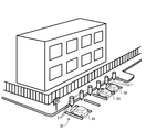
- the present invention relates to a charging device that charges a vehicle battery mounted on an electric vehicle, and in particular, a plurality of units such as a private pay parking lot, a customer collection facility such as a shopping mall, or a parking lot provided in an apartment house.
- the present invention relates to a charging device and a charging system that can be suitably applied to a charging system for charging an electric vehicle.
- Charging of electric vehicles can be divided into medium-speed charging (also called normal charging) performed for a long time with a relatively small current and rapid charging performed for a short time with a large current.
- medium-speed charging also called normal charging
- the charging method is, for example, for charging JEVS-G-101 to 105 (standards established by the Japan Electric Vehicle Association standard) or SAE-J1772 (EV / PHEV (electric vehicle / plug-in hybrid vehicle) defined by the American Automotive Engineering Association) Standards related to connectors) are used.
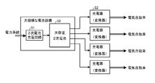
- a conventional charging station capable of rapid charging includes, for example, a large-scale battery facility including a secondary battery charging circuit 51 and a large-capacity secondary battery 52, and a large-capacity secondary battery. It comprises a plurality of chargers 53 connected to the output of the battery 52. Then, power from the power system is stored in the large capacity secondary battery 52 through the secondary battery charging circuit 51, the charging power of the large capacity secondary battery 52 is discharged, and each electric vehicle 20 is connected through each charger 53. The vehicle battery can be rapidly charged simultaneously.
- the charger illustrated in FIG. 7 includes a secondary battery charging circuit 51A, a small-capacity secondary battery 52A, and a converter 53A, and discharges the small-capacity secondary battery 52A in the charger to produce an electric vehicle.
- the vehicle battery is charged.
- FIG. 8 shows another example of the prior art (see FIG. 1 of Patent Document 1).
- 8 includes a battery charger 21, an external power supply side connector 22, a plurality of capacitors 23, a vehicle side connector 25, a vehicle charger 26, and a charge control unit that controls the operation of each device. 28, for example, by controlling the opening / closing operation of the relay in the vehicle-side connector 25 by the charging control unit 28, the charger connector 3A- connected to each charger (capacitor 23) and each electric vehicle 20 3C can be connected in any combination. Then, when charging the vehicle battery, among the capacitors excluding the battery being charged and the battery being discharged to the vehicle battery, the battery having the smallest charge capacity is connected to the vehicle battery, and the battery is discharged. The vehicle battery is charged (see paragraph 0008 of Patent Document 1).
- secondary batteries are divided into a plurality of groups for effective use.
- the configuration and control method are complicated, and it is difficult to increase the number of secondary batteries and charging vehicles. is there.
- the present invention has been made in view of the above-described problems, and the object of the present invention is to improve the above-described drawbacks when a plurality of chargers are installed, and to compare private parking lots and customer collection facilities. It is an object of the present invention to provide a charging device for an electric vehicle that can be applied to a small parking lot and can exchange electric power with the same type of charging device installed in the same area. Furthermore, the objective of this invention is providing the charging device which can construct
- the present invention relates to a charging device and a charging system that can be suitably applied to a charging system intended for charging a plurality of electric vehicles.
- the charging device the above object of the present invention is mounted on an electric vehicle.
- a charging device for charging electric power to a vehicle battery and capable of mutually supplying power to another charging device of the same configuration adjacent to each other installed in the same area via the other charging device and a power cable A built-in secondary battery for charging the vehicle battery by storing the electric power from the power system and discharging the stored electric power, and the built-in secondary battery and an electric vehicle charging connector;
- An electric circuit opening and closing means for opening and closing a first electric circuit between the battery and a second electric circuit between the built-in secondary battery of the other charging device and the electric vehicle charging connector, and the electric vehicle
- the electric circuit opening / closing means is driven to close the first electric circuit and the second electric circuit when the built-in secondary battery of the own charging device is determined to have no necessary remaining amount. It is achieved
- the above object of the present invention is to And a communication unit capable of communicating information with the other charging device, wherein the control unit receives the remaining amount of the built-in secondary battery of the charging device from the other charging device through the communication unit. Rapidly charging the vehicle battery from a built-in secondary battery of the other charging device when it is determined that the received remaining amount is greater than or equal to the remaining amount required for the quick charge; When it is determined that the received remaining amount is not greater than the remaining amount necessary for the quick charge, the control unit automatically switches from the quick charge to the normal charge and charges the vehicle battery with the normal charge.
- the other charging device is one or two charging devices adjacent to the own charging device
- the built-in secondary battery is a low-capacity storage battery that can be charged only once.
- An open / close control circuit having an open / close switch as the electric circuit open / close means and a switch driving circuit as the control means, and the open / close switch is provided between the built-in secondary battery of the own charging device and the open / close control circuit.
- a first switch for opening and closing an electric circuit a second switch for opening and closing an electric circuit between one of the other charging devices adjacent to the own charging device and the own charging device; the opening and closing control circuit; and the electric vehicle charging.
- a third switch that opens and closes an electric circuit between the charging connector and a fourth switch that opens and closes an electric circuit between the other charging device adjacent to the charging device and the own charging device. thing, Are achieved more effectively.
- the object of the present invention is to provide two or more charging devices, and adjacent charging devices in the same area are connected to each other by a single power cable. Achieved.
- the present invention it is not necessary to install a large secondary battery, and it is possible to provide a charging device that can be installed in a relatively small parking lot such as a private parking lot or a customer collection facility.
- a charging device that can be installed in a relatively small parking lot such as a private parking lot or a customer collection facility.
- power can be interchanged with other charging devices installed in the same area, and even when using a small capacity secondary battery that can be charged only once, the same charging device can be used. Rapid charging can be performed continuously.
- the interconnection at the time of installation is simple, and only the charging devices having the same configuration are used, and the adjacent charging devices are connected with the power cable, and according to the number of vehicles to be charged.
- a charging system can be easily constructed.
- the communication means which can perform information communication between other adjacent charging devices, it is only necessary to communicate with only the adjacent charging device, so communication and control are facilitated.
- an electric vehicle including an electric vehicle and a PHEV will be referred to as an electric vehicle.
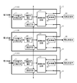
- FIG. 1 shows a configuration example of a charging system according to the present invention.
- the charging system according to the present invention is configured by connecting a plurality of chargers 1 (hereinafter referred to as “charging devices”) with a detachable power cable 2 in accordance with the number of vehicles to be charged.
- charging devices a plurality of chargers 1 (hereinafter referred to as “charging devices”) with a detachable power cable 2 in accordance with the number of vehicles to be charged.
- one charging device 1 can supply power to another charging device 1 of the same configuration adjacent to each other installed in the same area.
- the cables 2 are connected so as to be expanded.
- Each charging device 1 includes a secondary battery charging circuit 11 and a built-in secondary battery 12, and can be charged from an electric power system.
- the built-in secondary battery 12 is a built-in battery that stores power from the power system and discharges the stored power to charge the vehicle battery of the electric vehicle 20.
- the built-in secondary battery 12 Is connected to the converter 14 via the switching control circuit 13 and converted into necessary voltage / current by the converter 14 to charge the electric vehicle 20 as a load.
- the open / close control circuit 13 opens and closes the first electric circuit between the built-in secondary battery 12 of the own charging device 1 and the electric vehicle charging connector (between the converter 14 in this example) and other charging devices. 1 operates as an electric circuit opening / closing means for opening and closing the second electric circuit between the built-in secondary battery 12 and the electric vehicle charging connector (in this example, between the converter 14 of the own charging device 1).
- the open / close control circuit 13 has a control means.
- the control means 13 has a required remaining capacity in the built-in secondary battery of its own charging device.
- the electric circuit opening / closing means is driven to close the first electric circuit and open the second electric circuit, and from the built-in secondary battery of the other charging device to the electric vehicle charging connector of the own charging device (not shown) ) To quickly charge the vehicle battery of the electric vehicle 20.
- the charging device 1 is provided with communication means 15, which exchanges data with other charging devices via the communication means 15 and controls the operation of the open / close control circuit 13.
- the communication means 15 either wired communication (known as LAN or EIA-485) or wireless communication (known as wireless LAN, Zigbee (registered trademark), or infrared communication) can be used. .
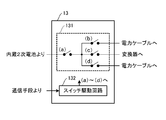
- FIG. 2 shows an example of the configuration of the open / close control circuit 13.
- the open / close switch 131 as the electric circuit open / close means described above, control of the open / close operation of the open / close switch 131, communication control with other charging devices, and the like.
- a switch drive circuit 132 as a control means to perform.
- the open / close control circuit 13 includes a plurality of switches (in this example, four switches 131 (a) to (d)) and the switch drive circuit 132, and as shown in FIG. Is connected to the open / close control circuit 13 via the power cable 2.
- Each of the switches (a) to (d) can be used with a mechanical contact such as a relay or a semiconductor switch (transistor or IGBT (insulated gate bipolar transistor)).
- the open / close control circuit 13 includes a first switch 131 (a) that opens and closes an electric circuit between the built-in secondary battery 12 and the open / close control circuit 13 in its own charging device, and one adjacent charge.
- the opening / closing operation is controlled by the switch drive circuit 132.
- the built-in secondary battery 12 in the charging device 1 may be, for example, a storage battery with a small capacity such that only one quick charging is possible. In the present embodiment, the same charging device 1 continuously performs quick charging. In some cases, rapid charging is performed using a built-in secondary battery in another charging device.
- the charging device 1 when the charging device 1 starts rapid charging according to the instruction on the electric vehicle 20 side, it is determined that there is not a necessary remaining amount in the built-in secondary battery in the own charging device 1.
- the built-in in the adjacent one or other charging device 1 is controlled by the switching control of the electric circuit by the open / close control circuit 13 in the self and other charging devices 1 (in this example, the adjacent one or other charging device 1).
- a secondary battery a built-in secondary battery that is not in use and has a remaining amount necessary for quick charging
- a converter 14 in its own charging device 1 are connected, and a built-in secondary battery in another charging device 1
- the electric vehicle 20 is charged via the converter 14 of the self.
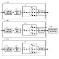
- FIG. 3A a case where the vehicle 20 that requires quick charging uses the charging device 1B will be described as an example.
- the charging device 1B closes the switches (a) and (c) in the open / close control circuit 13 and converts the built-in secondary battery 12 of the charging device 1B from the converter.
- the vehicle 20 is charged via the power supply 14, and the built-in secondary battery 12 is replenished from the power system.
- the charging device 1B checks the state (remaining amount) and the usage state (whether charging is in progress) of the adjacent 1A or 1C built-in secondary battery by the communication unit (communication unit 15 in FIG. 1). . From this result, the appropriate switching control circuit 13 is switched, and the built-in secondary battery 12 of the adjacent charging device 1 (charging device 1A in the example of FIG. 3A) is connected to the power cable 2 as shown in FIG. 3B.
- the charging device 1 ⁇ / b> B via the battery, it is possible to cope with rapid charging even when the secondary battery capacity is small.
- the operation control of the charging device 1 is performed by the switch driving circuit 132 (see FIG. 2) in the opening / closing control circuit 13 of the charging device 1.
- the switch driving circuit is controlled. 132 will be described as “control means”.
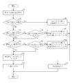
- the switches 131 (a) to (d) in the open / close control circuit 13 are all assumed to be open during standby.
- the control unit of the charging device 1 receives a quick charge request from the electric vehicle 20 (step S1), first, the control unit sets the status flag to be in use and sets its own built-in secondary battery 12 Whether or not the remaining amount is sufficient is checked (step S2), and if it is determined that the remaining amount of the built-in secondary battery 12 is sufficient (there is a remaining amount necessary for quick charging), the opening / closing control of itself By closing the switches (a) and (c) in the circuit 13 (step S3), the vehicle battery of the electric vehicle 20 is rapidly charged by the electric path between the self-built-in secondary battery 12 and the converter 14 (step S3). S4).
- step S2 determines whether the remaining capacity of the built-in secondary battery 12 is not sufficient.
- step S5 determines whether or not the remaining amount of the charging device 1A is sufficient.
- step S6 determines whether or not the remaining amount of the charging device 1A is sufficient.
- step S7 the built-in secondary battery 12 of one adjacent charging device 1A and the converter 14 in its own charging device 1B
- the vehicle battery of the electric vehicle 20 is rapidly charged by the electric circuit between them (step S4).
- step S5 determines whether or not the other adjacent charging device 1C is in use. If it is determined that the charging device 1C is not in use, it determines whether or not the remaining amount of the charging device 1C is sufficient. (Step S9).
- the control unit of the charging device 1B closes the switches (c) and (d) of its own charging device 1B and By closing the switches (a) and (b) of the charging device 1C (and making the status flag of the charging device 1C in use) (step S10), the built-in secondary battery 12 of the other adjacent charging device 1C
- the vehicle battery of the electric vehicle 20 is rapidly charged by the electric path between the converter 14 in the own charging device 1B (step S4).
- step S8 if it is determined in step S8 that the other adjacent charging device 1C is in use, or if it is determined in step S9 that the remaining charging device 1C is not sufficient. Then, the control means of the charging device 1B notifies the vehicle that rapid charging is not possible (step S11), and closes the switches (a) and (c) in its own open / close control circuit 13, thereby making its own built-in secondary Depending on the electrical path between the battery 12 and the converter 14 (or the switches (c) and (d) of the own charging device 1B and the switches (a) and (b) of the other adjacent charging device 1C are closed, The voltage / current necessary for medium-speed charging (normal charging) is converted through the converter 14, and the electric power is transferred between the built-in secondary battery 12 of the other adjacent charging device 1 ⁇ / b> C and its own converter 14. Performing medium-speed charging of a vehicle battery of the automobile 20 (step S12).
- the present invention it is possible to exchange power with other charging devices installed in the same area, and when using a small capacity secondary battery that can be quickly charged only once. However, it is possible to continuously perform rapid charging with the same charging device 1. Furthermore, the interconnection at the time of installation is simple, and the charging system according to the number of vehicles to be charged can be obtained simply by connecting the adjacent charging devices 1 with the power cable 2 using only the charging device 1 having the same configuration. It can be easily constructed. Moreover, since it is only necessary to communicate with only the adjacent charging device, there are advantages such as easy communication and control.
- the charging system of the structure which connected the three or more charging devices 1 is a partner's charging device.
- rapid charging can be performed continuously with the same charging device.
Landscapes
- Engineering & Computer Science (AREA)
- Power Engineering (AREA)
- Transportation (AREA)
- Mechanical Engineering (AREA)
- Charge And Discharge Circuits For Batteries Or The Like (AREA)
- Electric Propulsion And Braking For Vehicles (AREA)
- Secondary Cells (AREA)
Applications Claiming Priority (2)
| Application Number | Priority Date | Filing Date | Title |
|---|---|---|---|
| JP2012-055418 | 2012-03-13 | ||
| JP2012055418A JP5723811B2 (ja) | 2012-03-13 | 2012-03-13 | 電気自動車の充電装置及び充電システム |
Publications (1)
| Publication Number | Publication Date |
|---|---|
| WO2013137232A1 true WO2013137232A1 (ja) | 2013-09-19 |
Family
ID=49161138
Family Applications (1)
| Application Number | Title | Priority Date | Filing Date |
|---|---|---|---|
| PCT/JP2013/056750 Ceased WO2013137232A1 (ja) | 2012-03-13 | 2013-03-12 | 電気自動車の充電装置及び充電システム |
Country Status (2)
| Country | Link |
|---|---|
| JP (1) | JP5723811B2 (https=) |
| WO (1) | WO2013137232A1 (https=) |
Cited By (9)
| Publication number | Priority date | Publication date | Assignee | Title |
|---|---|---|---|---|
| CN104600814A (zh) * | 2015-02-14 | 2015-05-06 | 戴国峰 | 一种停车场的悬挂式电动车充电系统 |
| JP2016063646A (ja) * | 2014-09-18 | 2016-04-25 | 株式会社豊田自動織機 | 受電システム及びマスタ受電装置 |
| WO2016199222A1 (ja) * | 2015-06-09 | 2016-12-15 | 株式会社東芝 | 充電システム |
| EP3521099A1 (de) * | 2018-02-06 | 2019-08-07 | Dr. Ing. h.c. F. Porsche AG | Ladesystem mit mindestens einer ladesäule für elektrofahrzeuge und verfahren zum laden eines oder mehrerer elektrofahrzeuge |
| EP3508371A4 (en) * | 2016-09-26 | 2019-09-04 | Huawei Technologies Co., Ltd. | LOADING COLUMN |
| CN110854974A (zh) * | 2018-08-02 | 2020-02-28 | 奥迪股份公司 | 用于电动车的充电设备 |
| WO2021123702A1 (en) * | 2019-12-18 | 2021-06-24 | Zpn Energy Limited | Commissioning a system for charging electric vehicles |
| US11600996B2 (en) | 2017-03-24 | 2023-03-07 | The Noco Company | Electric vehicle (EV) fast recharge station and system |
| US11949274B2 (en) | 2017-03-24 | 2024-04-02 | The Noco Company | Electric vehicle (EV) fast recharge station and system |
Families Citing this family (15)
| Publication number | Priority date | Publication date | Assignee | Title |
|---|---|---|---|---|
| JP6071923B2 (ja) * | 2014-02-27 | 2017-02-01 | 株式会社東芝 | 充電システム |
| EP3295539A1 (en) * | 2015-05-14 | 2018-03-21 | Efacec Electric Mobility, S.A. | Fast charging system for electric vehicles |
| JP6548262B2 (ja) | 2015-12-25 | 2019-07-24 | ニチコン株式会社 | 電動車のための充電システム |
| KR101759246B1 (ko) * | 2016-01-21 | 2017-07-18 | 옴니시스템 주식회사 | 전기자동차 충전시스템 |
| DE102017116887A1 (de) | 2017-07-26 | 2019-01-31 | Wobben Properties Gmbh | Ladestation mit dynamischer Ladestromverteilung |
| DE102017116886A1 (de) | 2017-07-26 | 2019-01-31 | Wobben Properties Gmbh | Ladestation mit dynamischer Ladestromverteilung |
| DE102018204057A1 (de) * | 2018-03-16 | 2019-09-19 | Schäfer Elektronik Gmbh | Ladestation für Elektrofahrzeuge mit mindestens zwei Ladesäulen |
| JP6655657B2 (ja) * | 2018-05-23 | 2020-02-26 | 株式会社ダイヘン | 車両用充電装置、駐車場及び充電方法 |
| JP7454431B2 (ja) * | 2020-04-02 | 2024-03-22 | 河村電器産業株式会社 | 充電ステーション |
| JP2021191045A (ja) * | 2020-05-26 | 2021-12-13 | 河村電器産業株式会社 | 車両充電システム |
| CN117837047A (zh) * | 2021-08-16 | 2024-04-05 | 株式会社帕瓦艾克司 | 急速充电装置及系统 |
| CN114801832B (zh) * | 2022-06-24 | 2022-09-23 | 小米汽车科技有限公司 | 充电设备、方法、装置、车辆、电子设备和存储介质 |
| KR102777394B1 (ko) * | 2023-10-10 | 2025-03-07 | 쿨사인 주식회사 | 가변형 충전 전력공급시스템 |
| KR102691919B1 (ko) * | 2023-11-09 | 2024-08-05 | 쿨사인 주식회사 | 고효율 분산 전력 공급 충전시스템 |
| CN117922347B (zh) * | 2023-12-19 | 2026-03-10 | 华为数字能源技术有限公司 | 功率分配装置、充电设备、储能设备和充电系统 |
Citations (5)
| Publication number | Priority date | Publication date | Assignee | Title |
|---|---|---|---|---|
| JP2010239714A (ja) * | 2009-03-30 | 2010-10-21 | Japan Research Institute Ltd | 充電制御装置、電池パック、車両および充電制御方法 |
| JP2011036096A (ja) * | 2009-08-05 | 2011-02-17 | Denso Corp | 給電コントローラおよび給電システム |
| JP2011239559A (ja) * | 2010-05-10 | 2011-11-24 | Takaoka Electric Mfg Co Ltd | 電気自動車の充電装置 |
| JP2012210039A (ja) * | 2011-03-29 | 2012-10-25 | Denso Corp | 電力分配装置 |
| JP2013013208A (ja) * | 2011-06-29 | 2013-01-17 | Fuji Electric Co Ltd | 充電器 |
Family Cites Families (3)
| Publication number | Priority date | Publication date | Assignee | Title |
|---|---|---|---|---|
| JP5033697B2 (ja) * | 2008-03-31 | 2012-09-26 | 株式会社日立製作所 | 家庭用充放電装置及びその制御方法 |
| JPWO2011118187A1 (ja) * | 2010-03-23 | 2013-07-04 | パナソニック株式会社 | 充電制御装置、充電システムおよび充電制御方法 |
| JP2012019602A (ja) * | 2010-07-07 | 2012-01-26 | Jfe Engineering Corp | 急速充電方法及び装置 |
-
2012
- 2012-03-13 JP JP2012055418A patent/JP5723811B2/ja active Active
-
2013
- 2013-03-12 WO PCT/JP2013/056750 patent/WO2013137232A1/ja not_active Ceased
Patent Citations (5)
| Publication number | Priority date | Publication date | Assignee | Title |
|---|---|---|---|---|
| JP2010239714A (ja) * | 2009-03-30 | 2010-10-21 | Japan Research Institute Ltd | 充電制御装置、電池パック、車両および充電制御方法 |
| JP2011036096A (ja) * | 2009-08-05 | 2011-02-17 | Denso Corp | 給電コントローラおよび給電システム |
| JP2011239559A (ja) * | 2010-05-10 | 2011-11-24 | Takaoka Electric Mfg Co Ltd | 電気自動車の充電装置 |
| JP2012210039A (ja) * | 2011-03-29 | 2012-10-25 | Denso Corp | 電力分配装置 |
| JP2013013208A (ja) * | 2011-06-29 | 2013-01-17 | Fuji Electric Co Ltd | 充電器 |
Cited By (16)
| Publication number | Priority date | Publication date | Assignee | Title |
|---|---|---|---|---|
| JP2016063646A (ja) * | 2014-09-18 | 2016-04-25 | 株式会社豊田自動織機 | 受電システム及びマスタ受電装置 |
| CN104600814A (zh) * | 2015-02-14 | 2015-05-06 | 戴国峰 | 一种停车场的悬挂式电动车充电系统 |
| WO2016199222A1 (ja) * | 2015-06-09 | 2016-12-15 | 株式会社東芝 | 充電システム |
| EP3508371A4 (en) * | 2016-09-26 | 2019-09-04 | Huawei Technologies Co., Ltd. | LOADING COLUMN |
| US10926655B2 (en) | 2016-09-26 | 2021-02-23 | Huawei Technologies Co., Ltd. | Charging pile |
| US11600996B2 (en) | 2017-03-24 | 2023-03-07 | The Noco Company | Electric vehicle (EV) fast recharge station and system |
| US12512691B2 (en) | 2017-03-24 | 2025-12-30 | The Noco Company | Electric vehicle (EV) fast recharge station and system |
| US12328018B2 (en) | 2017-03-24 | 2025-06-10 | The Noco Company | Electric vehicle (EV) fast charge station and system |
| US11949274B2 (en) | 2017-03-24 | 2024-04-02 | The Noco Company | Electric vehicle (EV) fast recharge station and system |
| CN110116645A (zh) * | 2018-02-06 | 2019-08-13 | 保时捷股份公司 | 充电系统以及给电动车辆充电的方法 |
| US10994628B2 (en) | 2018-02-06 | 2021-05-04 | Dr. Ing. H.C. F. Porsche Aktiengesellschaft | Charging system having at least one charging column for electric vehicles and method for charging one or more electric vehicles |
| EP3521099A1 (de) * | 2018-02-06 | 2019-08-07 | Dr. Ing. h.c. F. Porsche AG | Ladesystem mit mindestens einer ladesäule für elektrofahrzeuge und verfahren zum laden eines oder mehrerer elektrofahrzeuge |
| CN110854974A (zh) * | 2018-08-02 | 2020-02-28 | 奥迪股份公司 | 用于电动车的充电设备 |
| GB2604550A (en) * | 2019-12-18 | 2022-09-07 | Zpn Energy Ltd | Commissioning a system for charging electric vehicles |
| WO2021123702A1 (en) * | 2019-12-18 | 2021-06-24 | Zpn Energy Limited | Commissioning a system for charging electric vehicles |
| GB2604550B (en) * | 2019-12-18 | 2025-02-26 | Zpn Energy Ltd | Commissioning a system for charging electric vehicles |
Also Published As
| Publication number | Publication date |
|---|---|
| JP5723811B2 (ja) | 2015-05-27 |
| JP2013192310A (ja) | 2013-09-26 |
Similar Documents
| Publication | Publication Date | Title |
|---|---|---|
| JP5723811B2 (ja) | 電気自動車の充電装置及び充電システム | |
| JP6832751B2 (ja) | 電荷移動管理方法および電荷移動装置 | |
| CN109808522B (zh) | 用于车辆的复合双向集成充电器 | |
| US11958409B2 (en) | Vehicle and method of notifying charging information of vehicle | |
| US10259336B2 (en) | Charging a battery using interpack switch | |
| JP5493441B2 (ja) | 車車間充電方法、車車間充電用ケーブルおよび電動車両 | |
| CN103568861B (zh) | 具有预充电功能的低成本充电器电路 | |
| CN102906959B (zh) | 用于电动车辆的充电系统 | |
| EP3800083B1 (en) | Power-supply and recharge groups of an electric vehicle and methods thereof | |
| CN111264014A (zh) | 蓄电系统 | |
| US10589633B2 (en) | Fast charging battery system | |
| WO2012127673A1 (ja) | 電力変換設備、電動車両および電動車両の充電システム | |
| JP2010273427A (ja) | 電動車両用電源装置および組電池 | |
| CN105934864A (zh) | 从电动车辆向电动车辆充电的方法 | |
| US20190225096A1 (en) | Vehicle | |
| CN107074125A (zh) | 用于运行机动车中的蓄能装置的方法和机动车 | |
| JP2021013241A (ja) | 車両 | |
| JP2013013208A (ja) | 充電器 | |
| WO2023216733A1 (zh) | 动力电池控制电路、系统及其控制方法 | |
| US20250026208A1 (en) | Vehicle-to-vehicle charging box and method for direct current fast-charging using the same | |
| KR20190100261A (ko) | 재충전가능한 전기 또는 하이브리드 차량의 관리를 위한 방법 및 시스템 | |
| US20260084564A1 (en) | Mobile charging station and method for charging electric vehicles in a mobile manner | |
| CN119705127A (zh) | 多输入电动车辆充电系统 | |
| WO2012059988A1 (ja) | 充電装置およびそれを備える車両 | |
| US20260025072A1 (en) | Vehicle-to-vehicle charging using voltage converter system with bypass switches for reduced losses |
Legal Events
| Date | Code | Title | Description |
|---|---|---|---|
| 121 | Ep: the epo has been informed by wipo that ep was designated in this application |
Ref document number: 13761335 Country of ref document: EP Kind code of ref document: A1 |
|
| NENP | Non-entry into the national phase |
Ref country code: DE |
|
| 122 | Ep: pct application non-entry in european phase |
Ref document number: 13761335 Country of ref document: EP Kind code of ref document: A1 |