WO2013133209A1 - エマルション調製用デバイス及びエマルション調製方法 - Google Patents
エマルション調製用デバイス及びエマルション調製方法 Download PDFInfo
- Publication number
- WO2013133209A1 WO2013133209A1 PCT/JP2013/055844 JP2013055844W WO2013133209A1 WO 2013133209 A1 WO2013133209 A1 WO 2013133209A1 JP 2013055844 W JP2013055844 W JP 2013055844W WO 2013133209 A1 WO2013133209 A1 WO 2013133209A1
- Authority
- WO
- WIPO (PCT)
- Prior art keywords
- mesh
- cylindrical
- emulsion
- fibers
- cylindrical portion
- Prior art date
- Legal status (The legal status is an assumption and is not a legal conclusion. Google has not performed a legal analysis and makes no representation as to the accuracy of the status listed.)
- Ceased
Links
Images



Classifications
-
- B—PERFORMING OPERATIONS; TRANSPORTING
- B01—PHYSICAL OR CHEMICAL PROCESSES OR APPARATUS IN GENERAL
- B01F—MIXING, e.g. DISSOLVING, EMULSIFYING OR DISPERSING
- B01F25/00—Flow mixers; Mixers for falling materials, e.g. solid particles
- B01F25/40—Static mixers
- B01F25/45—Mixers in which the materials to be mixed are pressed together through orifices or interstitial spaces, e.g. between beads
- B01F25/452—Mixers in which the materials to be mixed are pressed together through orifices or interstitial spaces, e.g. between beads characterised by elements provided with orifices or interstitial spaces
- B01F25/4523—Mixers in which the materials to be mixed are pressed together through orifices or interstitial spaces, e.g. between beads characterised by elements provided with orifices or interstitial spaces the components being pressed through sieves, screens or meshes which obstruct the whole diameter of the tube
-
- B—PERFORMING OPERATIONS; TRANSPORTING
- B01—PHYSICAL OR CHEMICAL PROCESSES OR APPARATUS IN GENERAL
- B01F—MIXING, e.g. DISSOLVING, EMULSIFYING OR DISPERSING
- B01F23/00—Mixing according to the phases to be mixed, e.g. dispersing or emulsifying
- B01F23/40—Mixing liquids with liquids; Emulsifying
- B01F23/41—Emulsifying
-
- B—PERFORMING OPERATIONS; TRANSPORTING
- B01—PHYSICAL OR CHEMICAL PROCESSES OR APPARATUS IN GENERAL
- B01F—MIXING, e.g. DISSOLVING, EMULSIFYING OR DISPERSING
- B01F25/00—Flow mixers; Mixers for falling materials, e.g. solid particles
- B01F25/40—Static mixers
- B01F25/45—Mixers in which the materials to be mixed are pressed together through orifices or interstitial spaces, e.g. between beads
- B01F25/451—Mixers in which the materials to be mixed are pressed together through orifices or interstitial spaces, e.g. between beads characterised by means for moving the materials to be mixed or the mixture
- B01F25/4512—Mixers in which the materials to be mixed are pressed together through orifices or interstitial spaces, e.g. between beads characterised by means for moving the materials to be mixed or the mixture with reciprocating pistons
-
- B—PERFORMING OPERATIONS; TRANSPORTING
- B01—PHYSICAL OR CHEMICAL PROCESSES OR APPARATUS IN GENERAL
- B01F—MIXING, e.g. DISSOLVING, EMULSIFYING OR DISPERSING
- B01F25/00—Flow mixers; Mixers for falling materials, e.g. solid particles
- B01F25/40—Static mixers
- B01F25/45—Mixers in which the materials to be mixed are pressed together through orifices or interstitial spaces, e.g. between beads
- B01F25/452—Mixers in which the materials to be mixed are pressed together through orifices or interstitial spaces, e.g. between beads characterised by elements provided with orifices or interstitial spaces
- B01F25/4524—Mixers in which the materials to be mixed are pressed together through orifices or interstitial spaces, e.g. between beads characterised by elements provided with orifices or interstitial spaces the components being pressed through foam-like inserts or through a bed of loose bodies, e.g. balls
- B01F25/45242—Mixers in which the materials to be mixed are pressed together through orifices or interstitial spaces, e.g. between beads characterised by elements provided with orifices or interstitial spaces the components being pressed through foam-like inserts or through a bed of loose bodies, e.g. balls through a bed of fibres, steel wool or wood chips
-
- B—PERFORMING OPERATIONS; TRANSPORTING
- B01—PHYSICAL OR CHEMICAL PROCESSES OR APPARATUS IN GENERAL
- B01F—MIXING, e.g. DISSOLVING, EMULSIFYING OR DISPERSING
- B01F33/00—Other mixers; Mixing plants; Combinations of mixers
- B01F33/50—Movable or transportable mixing devices or plants
- B01F33/501—Movable mixing devices, i.e. readily shifted or displaced from one place to another, e.g. portable during use
- B01F33/5011—Movable mixing devices, i.e. readily shifted or displaced from one place to another, e.g. portable during use portable during use, e.g. hand-held
- B01F33/50112—Movable mixing devices, i.e. readily shifted or displaced from one place to another, e.g. portable during use portable during use, e.g. hand-held of the syringe or cartridge type
Definitions
- the present invention relates to a device and a preparation method for forming an emulsion by mixing a continuous phase and a dispersed phase.
- Patent Document 1 does not have a filter part
- the connector of Patent Document 2 uses a glass membrane porous body for the filter part, and all the connectors of Documents are filled with fibers. It does not have a filter part.
- Patent Document 3 relates to a filter filled with fibers, but does not describe an emulsion preparation device. Also, Patent Document 4 does not show a connector having a filter part filled with fibers.
- An object of the present invention is to provide an emulsion preparation device and an emulsion preparation method capable of forming an emulsion in chemical solutions of various compositions and having a relatively low sliding resistance.
- the present invention is the emulsion preparation device having a filter part, wherein the filter part is constituted by the first and second mesh parts and fibers, and the fibers are the first mesh part and the first mesh part. The space between the two mesh portions is filled. That is, the present invention provides the following (1) to (12).
- an emulsion preparation device having a filter part
- the filter part is composed of first and second mesh parts and fibers, The fibers are filled in a space between the first mesh portion and the second mesh portion, A device for preparing an emulsion.
- One side or both sides of the filter part can be connected to a syringe, Between the two syringes connected to both sides of the filter part, or between the syringe connected to one side and the container connected to the other side, the continuous phase and the dispersed phase are When reciprocating through the filter part, an emulsion is formed.
- the first mesh portion and / or the second mesh portion is a disc.
- the emulsion preparation device according to (1) or (2) above.
- the mesh portion has a large number of arc-shaped through holes arranged uniformly in a concentric manner, and all the through holes have the same area within an error range of 10%.
- the emulsion preparation device according to (3) above.
- the fiber is a hydrophobic fiber.
- the hydrophobic fiber is polyester.
- the fiber is a hydrophilic fiber.
- the fiber has a 50 to 150 denier, the are filled so that there the space 1 mm 3 per 2.5 ⁇ 17.7 mm, The emulsion preparation device according to any one of (1) to (7) above. (9) the fiber has a 50 to 150 denier, the are filled so that there the space 1 mm 3 per 5.0 ⁇ 9.9 mm, The device for preparing an emulsion according to any one of (1) to (8) above.
- the first cylindrical body is composed of a first cylindrical part and a second cylindrical part following the first cylindrical part,
- the second cylindrical portion is smaller in diameter than the first cylindrical portion
- the first mesh portion is formed at a boundary between the first cylindrical portion and the second cylindrical portion, and the fibers are pushed toward the first mesh portion,
- the second mesh part is pressed toward the fiber, and thereby the filter part composed of the first mesh part, the fiber assembly, and the second mesh part is configured
- the second mesh portion is a bottom surface of a concave lid that fits into the first cylindrical portion,
- the concave lid is configured such that an outer flange on an opening peripheral edge abuts on the opening peripheral edge of the first cylindrical portion, thereby bringing the second mesh portion into a predetermined distance with respect to the first mesh portion in the first cylindrical portion.
- the first cylindrical body and the second cylindrical body are joined together by an outer flange on the opening periphery of the first cylindrical portion and an outer flange on the opening periphery of the second cylinder,
- the emulsion preparation device according to any one of (1) to (9) above.
- the first cylindrical body is composed of a first cylindrical part and a second cylindrical part following the first cylindrical part,
- the second cylindrical portion is smaller in diameter than the first cylindrical portion
- the first mesh portion is formed at a boundary between the first cylindrical portion and the second cylindrical portion, and the fibers are pushed toward the first mesh portion,
- the second mesh part is pressed toward the fiber, and thereby the filter part composed of the first mesh part, the fiber assembly, and the second mesh part is configured
- the second mesh portion is a bottom surface of a concave lid that fits into the first cylindrical portion,
- the concave lid is configured such that an outer flange on an opening peripheral edge abuts on the opening peripheral edge of the first cylindrical portion, thereby bringing the second mesh portion into a predetermined distance with respect to the first mesh portion in the first cylindrical portion.
- the first cylindrical body and the second cylindrical body are joined together by an outer flange on the opening periphery of the first cylindrical portion and an outer flange on the opening periphery of the second cylinder,
- the fiber assembly is located in the center in the longitudinal direction;
- the external shape is bilaterally symmetrical in the longitudinal direction.
- a method for preparing an emulsion comprising using the device for preparing an emulsion according to any one of (1) to (11) above.
- the emulsion preparation method of the present invention is characterized by using the above-described emulsion preparation device of the present invention.
- emulsions can be formed in chemical solutions having various compositions, and the sliding resistance can be made relatively small.
- FIG. 2 is a cross-sectional side view of the device of FIG.
- FIG. 3 is a partial view taken along the line III in FIG. 1 and shows a first mesh portion. It is a whole side view of the preparation instrument using the device for emulsion preparation of 2nd Embodiment of this invention.
- FIG. 5 is a side view of the device of FIG. 4.
- FIG. 5 is a cross-sectional side view of the device of FIG.
- FIG. 5 is a perspective side view of the device of FIG. 4. It is a figure which shows the modification of a 1st mesh part. It is a figure which shows another modification of a 1st mesh part.
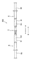
- FIG. 1 is an overall side view of a preparation tool using the emulsion preparation device according to the first embodiment of the present invention.
- the preparation instrument 100 comprises a device 1 and syringes 8 and 9 connected to both sides of the device 1.
- the syringe 8 includes a cylindrical body 81 and a pusher 82.
- the syringe 9 includes a cylindrical body 91 and a pusher 92.
- FIG. 2 is a cross-sectional side view of the device 1.
- the first cylindrical body 2 and the second cylindrical body 4 are joined together by outer flanges 29 and 49 at the periphery of the opening.
- the device 1 is preferably composed of a sterilizable material.
- the first cylindrical body 2 includes a first cylindrical portion 21 and a second cylindrical portion 22 that follows the first cylindrical portion 21.
- the second cylindrical portion 22 has a smaller diameter than the first cylindrical portion 21.
- a first mesh portion 31 is formed at the boundary between the first cylindrical portion 21 and the second cylindrical portion 22.
- the fiber 32 is pushed toward the first mesh portion 31, and the second mesh portion 33 is pushed toward the fiber 32. That is, the fiber 32 is pushed and filled in the space 30 between the first mesh portion 31 and the second mesh portion 33.
- the first mesh portion 31, the fibers 32, and the second mesh portion 33 constitute the filter unit 10.
- the 1st mesh part 31 and the 2nd mesh part 33 are discs which have many through-holes.
- the fibers 32 filled in the space 30 constitute a fiber assembly that fills the space 30. In the fiber assembly, a large number of minute gaps are formed between the fibers. Therefore, in the filter part 10, the liquid can come and go from the first mesh part 31 to the second mesh part 33 or vice versa by passing through the gap of the fiber assembly. .
- the second mesh portion 33 is the bottom surface of the concave lid 23 that fits into the first cylindrical portion 21.
- the concave lid 23 is configured such that the outer mesh 231 of the opening periphery contacts the opening periphery 211 of the first cylindrical portion 21, thereby causing the second mesh portion 33 to be in contact with the first mesh portion 31 in the first cylindrical portion 21. It is located at a predetermined distance and in parallel.
- a luer taper 48 is formed at the opening end of the second cylindrical body 4.
- a luer taper 28 is also formed at the opening end of the second cylindrical portion 22 of the first cylindrical body 2.
- the first cylinder 2 and the second cylinder 4 communicate with each other through openings 20 and 40 having the same size.
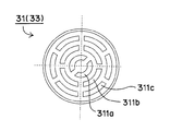
- FIG. 3 is a view taken along the arrow III of the first mesh portion 31.
- the first mesh portion 31 has a large number of arc-shaped through-holes 311 (that is, the through-holes 311a, 311b, and 311c) that are equally arranged concentrically. All the through holes 311 have the same area within an error range of 10%.
- the second mesh portion 33 also has the same configuration as the first mesh portion 31.
- the fiber 32 is a hydrophobic fiber.
- the hydrophobic fiber polyester, polypropylene, polystyrene, Teflon (registered trademark), nylon, polyvinyl chloride, acrylic, and the like can be used, and polyester is preferable.
- the fibers 32 are preferably crimped.
- the fibers 32 have a denier of 50 to 150, and are filled in the space 30 so that there is 2.5 to 17.7 mm per 1 mm 3 of the space 30.
- the filling is preferably performed so as to exist at 4.0 to 12.0 mm, and more preferably filled so as to exist at 5.0 to 9.9 mm.
- the preparation instrument 100 shown in FIG. 1 is used as follows. That is, the emulsion preparation method using the device 1 is as follows. In the preparation tool 100, the syringe 8 is filled with the dispersed phase 101, and the syringe 9 is filled with the continuous phase 102, but the opposite may be possible.
- the pusher of one syringe press the pusher of one syringe.
- the pusher 82 of the syringe 8 is pumped in the A direction.
- the dispersed phase 101 moves to the syringe 9 through the device 1, and the pusher 92 of the syringe 9 is pushed in the A direction.
- the dispersed phase 101 is slightly mixed with the continuous phase 102 in the syringe 9.
- both phases 101 and 102 in a slightly mixed state pass through the filter unit 10 in the device 1. That is, both phases 101 and 102 in a slightly mixed state first pass through the second mesh portion 33, and then disperse and mix, then pass through the fibers 32, and further disperse and mix at that time, and It passes through the first mesh portion 31 and further disperses and mixes at that time. Therefore, both phases 101 and 102 that have moved to the syringe 8 are in a more mixed state than when they were in the syringe 9.
- both phases 101 and 102 in a more mixed state move to the syringe 9 through the device 1, and the pusher 92 of the syringe 9 is pushed in the A direction.
- both phases 101 and 102 in a more mixed state pass through the filter unit 10 in the device 1. That is, both phases 101 and 102 in a more mixed state first pass through the first mesh portion 31, and then disperse and mix, then pass through the fibers 32, then further disperse and mix, and It passes through the second mesh portion 33 and further disperses and mixes at that time. Therefore, both phases 101 and 102 that have moved to the syringe 9 are in a more mixed state than when they were in the syringe 8.
- the pumping operation of the pusher 82 of the syringe 8 and the pumping operation of the pusher 92 of the syringe 9 are repeated alternately.
- the number of pumping operations is preferably 50 times or less, more preferably 10 times or less, and most preferably 5 times or less.
- the mixed state of both phases 101 and 102 further progresses to a target emulsion state.
- the fibers 32 are hydrophobic fibers, the oil phase becomes a continuous phase, the water phase becomes a dispersed phase, and a water-in-oil emulsion is formed.
- the fibers 32 have 50 to 150 denier and are filled in the space 30 so as to exist at 2.5 to 17.7 mm per 1 mm 3 of the space 30. Both phases 101, 102 can be efficiently dispersed and mixed to form the desired emulsion.
- the through holes 311 having the same area are arranged uniformly, so that the dispersion of both phases 101 and 102 occurs evenly in the entire area of the mesh portion. Therefore, also from this point, both phases 101 and 102 can be efficiently dispersed and mixed.
- the fibers 32 filled in the space 30 have a predetermined thickness and length, and the first mesh portion 31 and the second mesh portion 33 have many arc-shaped through holes 311. Because of the large porosity, the sliding resistance during the pumping operation can be reduced. Therefore, operability can be improved.
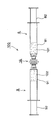
- FIG. 4 is an overall side view of a preparation instrument using the emulsion preparation device according to the second embodiment of the present invention.
- the preparation instrument 100 includes a device 1A and syringes 8 and 9 connected to both sides of the device 1A.
- the syringe 8 includes a cylindrical body 81 and a pusher 82.
- the syringe 9 includes a cylindrical body 91 and a pusher 92.
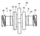
- FIG. 5 is a side view of the device 1A.
- FIG. 6 is a cross-sectional side view of the device 1A.
- the device 1A is different from the device 1 of the first embodiment in the following points.
- the aggregate of the fibers 32 filling the space 30 is located at the center in the longitudinal direction.
- the external shape is symmetrical in the longitudinal direction.
- the liquid level adjusting ribs 93 and 95 are provided.
- the device 1A is integrally formed by joining the first cylindrical body 2 and the second cylindrical body 4 by outer flanges 29 and 49 at the periphery of the opening.
- the device 1A is preferably made of a sterilizable material.
- the first cylindrical body 2 includes a first cylindrical portion 21 and a second cylindrical portion 22 that follows the first cylindrical portion 21.
- the second cylindrical portion 22 has a smaller diameter than the first cylindrical portion 21.
- a first mesh portion 31 is formed at the boundary between the first cylindrical portion 21 and the second cylindrical portion 22.
- the fiber 32 is pushed toward the first mesh portion 31, and the second mesh portion 33 is pushed toward the fiber 32. That is, the space 30 between the first mesh portion 31 and the second mesh portion 33 is filled with the fibers 32.
- the first mesh portion 31, the fibers 32, and the second mesh portion 33 constitute the filter unit 10.
- the 1st mesh part 31 and the 2nd mesh part 33 are discs which have many through-holes.
- the fibers 32 filled in the space 30 constitute a fiber assembly that fills the space 30. In the fiber assembly, a large number of minute gaps are formed between the fibers. Therefore, in the filter part 10, the liquid can come and go from the first mesh part 31 to the second mesh part 33 or vice versa by passing through the gap of the fiber assembly. .
- the second mesh portion 33 is the bottom surface of the concave lid 23 that fits into the first cylindrical portion 21.
- the concave lid 23 is configured such that the outer mesh 231 of the opening periphery contacts the opening periphery 211 of the first cylindrical portion 21, thereby causing the second mesh portion 33 to be in contact with the first mesh portion 31 in the first cylindrical portion 21. It is located at a predetermined distance and in parallel.
- the first cylinder 2 and the second cylinder 4 communicate with each other through openings 20 and 40 having the same size.
- the aggregate of the fibers 32 filling the space 30 is located at the center in the longitudinal direction. That is, the space 30 is located at the center in the longitudinal direction.
- the external shape of the device 1A is symmetric in the longitudinal direction. That is, the first cylindrical body 2 has an outer flange 29 at the periphery of the opening, a large flange 91, a small flange 92, a liquid level adjusting rib 93, and a connection end 94, while the second The cylindrical body 4 has an outer flange 49 at the periphery of the opening, a liquid level adjusting rib 95, and a connection end portion 96.
- the large flange 91 is located at the center in the longitudinal direction, and both sides thereof
- the small flange 92 and the integrated outer flanges 29 and 49 are positioned in the same manner
- the liquid level adjusting rib 93 and the liquid level adjusting rib 95 are positioned in the same way on both sides thereof.
- the connection end portion 94 and the connection end portion 96 are similarly positioned on both sides thereof.
- the 1st mesh part 31, the fiber 32, and the 2nd mesh part 33 are the same as 1st Embodiment.
- the portions where the formed emulsion remains are spaces 71 and 72 as shown in FIG. 7, and the volume thereof is small. Therefore, according to the device 1A, the generation efficiency of the emulsion can be improved.
- the liquid level adjusting ribs 93 and 95 indicate the upper limit of the height position of the continuous phase and the dispersed phase at the time of air venting, when the pushers 82 and 92 are pushed for air venting. It is a standard. Therefore, according to the device 1A, the workability of air venting can be improved.
- the fiber 32 may be a hydrophilic fiber, for example, cotton, rayon, vinylon, or the like.
- the water phase becomes a continuous phase
- the oil phase becomes a dispersed phase
- an oil-in-water emulsion is formed.
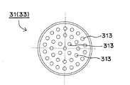
- the first mesh portion 31 and the second mesh portion 33 may be disks as shown in FIG. 8 or FIG. 8 has a large number of arc-shaped through-holes 312 (that is, through-holes 312a, 312b, and 312c) arranged in a concentric manner, but the area of the through-hole 312 is outside. The larger it is, the bigger it is.
- the 1st mesh part 31 and the 2nd mesh part 33 may have forms other than a disc, for example, may have the form of a block.
- Either one of the syringe 8 and the syringe 9 may be filled with a mixed liquid of a dispersed phase and a continuous phase. In this case, the other is not filled with liquid.
- the device 1 of Examples 1 to 14 and the device 1A of Example 15 were prepared.
- an emulsion confirmation test A and a sliding resistance evaluation test A were performed.
- the emulsion confirmation test B and the sliding resistance evaluation test B were done.
- the emulsion confirmation test B was done.
- the sliding resistance evaluation test C and the foreign material evaluation test were performed.
- Example 1 It is the device 1 of the structure of FIG. Specific dimensions are as follows.
- the fiber 32 is crimped and filled in the space 30.
- ⁇ Space 30 ⁇ 56.52mm 3 -Fiber 32: -Polyester-50 denier-1000 mm (17.7 mm exists per 1 mm 3 of space 30)
- First mesh portion 31 and second mesh portion 33 ⁇ Configuration of FIG. 3 ⁇ Through hole 311a: 0.43 mm 2 ⁇ Through hole 311b: 0.45 mm 2 ⁇ Through hole 311c: 0.46 mm 2 Open area: 5.42 mm 2
- Example 2 Compared to Example 1, only the following points are different. -Fiber 32: ⁇ 560 mm (9.9 mm per 1 mm 3 of space 30)
- Example 3 Compared to Example 1, only the following points are different. -Fiber 32: -280 mm (5.0 mm per 1 mm 3 of space 30)
- Example 4 Compared to Example 1, only the following points are different. -Fiber 32: 140 mm (2.5 mm exists per 1 mm 3 of space 30)
- Example 5 Compared to Example 1, only the following points are different. -Fiber 32: ⁇ 100 denier
- Example 6 Compared to Example 1, only the following points are different. -Fiber 32: 100 denier 560 mm (9.9 mm present per 1 mm 3 of space 30)
- Example 7 Compared to Example 1, only the following points are different. -Fiber 32: ⁇ 100 denier ⁇ 280 mm (5.0 mm per 1 mm 3 of space 30)
- Example 8 Compared to Example 1, only the following points are different. -Fiber 32: ⁇ 100 denier ⁇ 140 mm (2.5 mm per 1 mm 3 of space 30)
- Example 9 Compared to Example 1, only the following points are different. -Fiber 32: 150 denier 560 mm (9.9 mm exists per 1 mm 3 of space 30)
- Example 10 Compared to Example 1, only the following points are different. -Fiber 32: 150 denier 280 mm (5.0 mm per 1 mm 3 of space 30)
- Example 11 Compared to Example 1, only the following points are different.
- -Fiber 32 150 denier 140 mm (2.5 mm exists per 1 mm 3 of space 30)
- Example 12 Compared to Example 1, only the following points are different. -Fiber 32: -75 denier-280 mm (5.0 mm per 1 mm 3 of space 30)
- Example 13 Compared to Example 12, only the following points are different.
- First mesh portion 31 and second mesh portion 33 ⁇ Configuration of FIG. 4 ⁇ Through hole 312a: 0.17 mm 2 -Through hole 312b: 0.18 mm 2 ⁇ Through hole 312c: 0.35 mm 2 Open area: 4.92 mm 2
- Example 14 Compared to Example 12, only the following points are different.
- First mesh portion 31 and second mesh portion 33 ⁇ Configuration of FIG. 5 ⁇ Through hole 313: 0.07 mm 2 Open area: 2.45 mm 2
- Example 15 This is a device 1A configured as shown in FIG. Specific dimensions are as follows.
- the fiber 32 is crimped and filled in the space 30.
- ⁇ Space 30 ⁇ 56.52mm 3 -Fiber 32: -Polyester-75 denier-280 mm (5.0 mm per 1 mm 3 of space 30)
- First mesh portion 31 and second mesh portion 33 ⁇ Configuration of FIG. 3 ⁇ Through hole 311a: 0.43 mm 2 ⁇ Through hole 311b: 0.45 mm 2 ⁇ Through hole 311c: 0.46 mm 2 Open area: 5.42 mm 2
- Table 1 shows the test results. The test was performed three times.
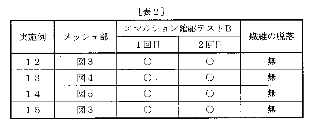
- Emsion confirmation test B [Test method] As shown in FIGS. 1 and 10, the following procedure was performed. (1) In the case of Examples 12 to 14, the preparation device 100 of FIG. 1 was prepared, and in the case of Example 15, the preparation device 100 of FIG. 4 was prepared.
- the syringe 8 was filled with 1.5 ml of a 2% L-arginine aqueous solution as a dispersed phase, ie, an aqueous phase, and the syringe 9 was filled with 1.5 ml of montanide as a continuous phase, ie, an oil phase.
- the syringes 8 and 9 are manufactured by B BRAUN and have a capacity of 5 ml.
- Table 2 shows the test results. The test was performed twice.
- the procedure was as follows.
- the preparation device 100 shown in FIG. 1 is prepared.
- the syringe 8 is filled with 1.5 ml of a 2% L-arginine aqueous solution as a dispersed phase, that is, an aqueous phase. Filled with 1.5 ml.
- the syringes 8 and 9 are manufactured by B BRAUN and have a capacity of 5 ml.
- the pusher 82 of the syringe 8 and the pusher 92 of the syringe 9 were manually pumped alternately, and this was repeated five times. Thereby, both phases were accommodated in the syringe 8.
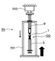
- the preparation tool 100 is installed on an autograph device 55 (model: EZ-L-500N, manufactured by Shimadzu Corporation) equipped with a support base 551 and a load cell 552, and the syringe 8 is pushed.
- the sliding resistance value at the time of alternately pushing the child 82 and the pusher 92 of the syringe 9 was measured by the load cell 552. Further, as the resistance value, an average value of the load when the presser strokes 5 to 15 mm was obtained.
- the sliding speeds of the pushers 82 and 92 of both syringes 8 and 9 were set to 500 mm / min and 1000 mm / min.
- Table 3 shows the test results. When the sliding speed of the presser 82 was 500 mm / min, the test was performed once, and when the slide speed was 1000 mm / min, the test was performed twice.
- the pumping operation speed is 500 mm / min
- the sliding resistance value is less than 70 N
- the operability is light and good, so it is indicated by “ ⁇ ”
- the pumping operation speed is 1000 mm / min
- the sliding resistance value is less than 140 N
- the operability is light and good. It was.
- the procedure was as follows.
- the preparation device 100 shown in FIG. 1 is prepared.
- the syringe 8 is filled with 1.5 ml of a 2% L-arginine aqueous solution as a dispersed phase, that is, an aqueous phase, and the continuous phase, that is, montanide as an oil phase is filled in the syringe 9. Filled with 1.5 ml.
- the syringes 8 and 9 are manufactured by B BRAUN and have a capacity of 5 ml.
- the pusher 82 of the syringe 8 and the pusher 92 of the syringe 9 were manually pumped alternately, and this was repeated five times.
- the preparation tool 100 is installed in an autograph device 55 (model AG-500BR, manufactured by Shimadzu Corporation) having a support base 551 and a load cell 552.
- the sliding resistance value at the time of alternately pushing the pushers 92 of the syringe 9 was measured by the load cell 552.
- the resistance value was measured for the first, second and third pumping operations. Further, as the resistance value, an average value of the load when the presser strokes 5 to 15 mm was obtained.
- the sliding speed was set to 500 mm / min.
- Example 12 the preparation tool 100 of FIG. 1 was prepared, and in the case of Example 15, the preparation tool 100 of FIG. 4 was prepared.
- the syringe 8 was filled with 1.5 ml of a physiological saline as a dispersed phase, that is, an aqueous phase
- the syringe 9 was filled with 1.5 ml of a montanide as a continuous phase, that is, an oil phase.
- the syringes 8 and 9 are manufactured by B BRAUN and have a capacity of 5 ml.
- the preparation instrument 100 is installed in an autograph apparatus 55 (model AG-Xplus, manufactured by Shimadzu Corporation) equipped with a support base 551 and a load cell 552, and a pusher 82 of a syringe 8
- the sliding resistance value at the time of alternately pushing the pushers 92 of the syringe 9 was measured by the load cell 552.
- the resistance value was measured for the first, second and third pumping operations. Further, as the resistance value, an average value of the load when the presser strokes 5 to 15 mm was obtained.
- the sliding speed was set to 500 mm / min.
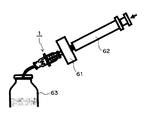
- FIG. 12 shows the state of the test for the device 1 of the twelfth embodiment.
- device 1A was used instead of device 1.
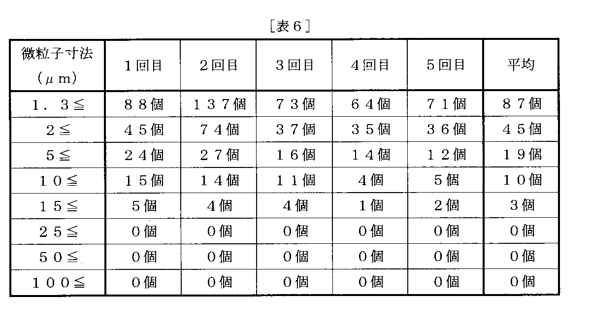
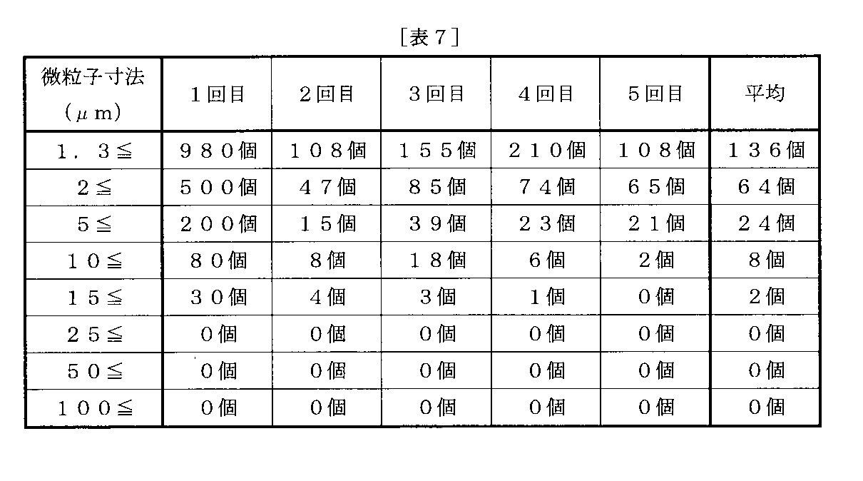
- a glass syringe 62 was attached to one end of the device 1 via a 0.8 ⁇ m membrane filter 61, and 10 ml of dust-free deionized water was vigorously discharged into the clean glass bottle 63 through the filter 61 and the device 1. This was done a total of 5 times.
- the filter 61 and the syringe 62 were removed and attached to the other end of the device 1 in the same manner, and the same operation was performed.
- about 100 ml of deionized water was recovered in the glass bottle 63. This deionized water is used as a specimen.
- the 16th revision Japanese Pharmacopoeia “Insoluble Insoluble Particle Testing Method, Method 1, Light Shielding Particle Measurement Method” was carried out. Specifically, the insoluble fine particles per 10 ml of the sample were measured four times with a liquid fine particle measuring machine (product name: RION KL-04), and the second to fourth measurement values were converted into the number of fine particles per container. This was done a total of 5 times, changing the specimen.
- the acceptable standard for insoluble fine particles that is, foreign matter is “6000 fine particles of 10 ⁇ m or more per container. , 600 or less fine particles of 25 ⁇ m or more ”.
- the acceptance criterion was made ten times strict, and “less than 600 particles of 10 ⁇ m or more and 60 particles of 25 ⁇ m or more per container”.
- both the devices 1 and 1A are excellent in the quality of foreign matter and have a cleanness sufficient for use as a medical device.
- the device for preparing an emulsion of the present invention can form an emulsion with respect to chemical solutions having various compositions, and can have a relatively small sliding resistance, and therefore has great industrial utility value.
Landscapes
- Chemical & Material Sciences (AREA)
- Chemical Kinetics & Catalysis (AREA)
- Dispersion Chemistry (AREA)
- Life Sciences & Earth Sciences (AREA)
- Engineering & Computer Science (AREA)
- Wood Science & Technology (AREA)
- Infusion, Injection, And Reservoir Apparatuses (AREA)
- Accessories For Mixers (AREA)
- Colloid Chemistry (AREA)
Abstract
Description
前記フィルタ部が、第1及び第2メッシュ部と繊維とによって、構成されており、
前記繊維が、第1メッシュ部と第2メッシュ部との間の空間内に充填されている、
ことを特徴とするエマルション調製用デバイス。
(2)前記フィルタ部の一方の側又は両方の側が、シリンジに連結可能となっており、
前記フィルタ部の両方の側に連結された2つのシリンジの間を、又は、一方の側に連結されたシリンジと他方の側に連結された容器との間を、連続相と分散相とが前記フィルタ部を通って往復移動すると、エマルションを形成する、
上記(1)記載のエマルション調製用デバイス。
(3)前記第1メッシュ部及び/又は前記第2メッシュ部が円板である、
上記(1)又は(2)に記載のエマルション調製用デバイス。
(4)前記メッシュ部は、同心円状に均等に配置された円弧状の多数の貫通孔を有しており、全ての前記貫通孔は、10%の誤差範囲内で同じ面積を有している、
上記(3)記載のエマルション調製用デバイス。
(5)前記繊維が、疎水性繊維である、
上記(1)~(4)のいずれか1つに記載のエマルション調製用デバイス。
(6)前記疎水性繊維が、ポリエステルである、
上記(5)記載のエマルション調製用デバイス。
(7)前記繊維が、親水性繊維である、
上記(1)~(4)のいずれか1つに記載のエマルション調製用デバイス。
(8)前記繊維は、50~150デニールを有しており、前記空間1mm3当たり2.5~17.7mm存在するように充填されている、
上記(1)~(7)のいずれか1つに記載のエマルション調製用デバイス。
(9)前記繊維は、50~150デニールを有しており、前記空間1mm3当たり5.0~9.9mm存在するように充填されている、
上記(1)~(8)のいずれか1つに記載のエマルション調製用デバイス。
前記第1円筒体は、第1円筒部と、前記第1円筒部に続く第2円筒部と、からなっており、
前記第2円筒部は、前記第1円筒部より小径であり、
前記第1円筒体において、前記第1円筒部と前記第2円筒部との境界には前記第1メッシュ部が形成されており、前記第1メッシュ部に向けて前記繊維が押し込まれており、前記繊維に向けて前記第2メッシュ部が押し付けられており、これにより、前記第1メッシュ部と前記繊維集合体と前記第2メッシュ部とからなる前記フィルタ部が構成されており、
前記第2メッシュ部は、前記第1円筒部に嵌合する凹形蓋の底面であり、
前記凹形蓋は、開口周縁の外フランジが前記第1円筒部の開口周縁に当接することによって、前記第2メッシュ部を、前記第1円筒部内において前記第1メッシュ部に対して所定距離に且つ平行に位置させており、
前記第1円筒体と前記第2円筒体とは、前記第1円筒部の前記開口周縁の外フランジと前記第2円筒体の開口周縁の外フランジとによって接合されて一体となっている、
上記(1)~(9)のいずれか1つに記載のエマルション調製用デバイス。
前記第1円筒体は、第1円筒部と、前記第1円筒部に続く第2円筒部と、からなっており、
前記第2円筒部は、前記第1円筒部より小径であり、
前記第1円筒体において、前記第1円筒部と前記第2円筒部との境界には前記第1メッシュ部が形成されており、前記第1メッシュ部に向けて前記繊維が押し込まれており、前記繊維に向けて前記第2メッシュ部が押し付けられており、これにより、前記第1メッシュ部と前記繊維集合体と前記第2メッシュ部とからなる前記フィルタ部が構成されており、
前記第2メッシュ部は、前記第1円筒部に嵌合する凹形蓋の底面であり、
前記凹形蓋は、開口周縁の外フランジが前記第1円筒部の開口周縁に当接することによって、前記第2メッシュ部を、前記第1円筒部内において前記第1メッシュ部に対して所定距離に且つ平行に位置させており、
前記第1円筒体と前記第2円筒体とは、前記第1円筒部の前記開口周縁の外フランジと前記第2円筒体の開口周縁の外フランジとによって接合されて一体となっており、
前記繊維集合体が、長手方向の中央に位置しており、
前記第1円筒体と前記第2円筒体とが接合されて一体となった状態において、外部形状が長手方向において左右対称である、
上記(1)~(9)のいずれか1つに記載のエマルション調製用デバイス。
図1は、本発明の第1実施形態のエマルション調製用デバイスを利用した調製器具の全体側面図である。この調製器具100は、デバイス1と、デバイス1の両方の側に連結されたシリンジ8、9と、からなっている。シリンジ8は、筒体81と押子82とからなっている。シリンジ9は、筒体91と押子92とからなっている。
図4は、本発明の第2実施形態のエマルション調製用デバイスを利用した調製器具の全体側面図である。この調製器具100は、デバイス1Aと、デバイス1Aの両方の側に連結されたシリンジ8、9と、からなっている。シリンジ8は、筒体81と押子82とからなっている。シリンジ9は、筒体91と押子92とからなっている。
(i)空間30を充たす繊維32の集合体が長手方向の中央に位置している。
(ii)外部形状が長手方向において左右対称である。
(iii)液面調整リブ93、95を有している。
なお、次のような変形構造を採用してもよい。
(1)繊維32は、親水性繊維でもよく、例えば綿、レーヨン、ビニロンなどでもよい。この場合は、水相が連続相となり、油相が分散相となり、水中油滴型エマルションが形成される。
(2)第1メッシュ部31及び第2メッシュ部33は、図8又は図9に示されるような円板でもよい。図8のメッシュ部は、同心円状に整列して配置された円弧状の多数の貫通孔312(すなわち、貫通孔312a、312b、312c)を有しているが、貫通孔312の面積は、外側に位置する程、大きくなっている。図9のメッシュ部は、均一に分散配置された多数の円孔313を有しており、全ての円孔313は同じ面積を有している。
(3)第1メッシュ部31及び第2メッシュ部33は、円板以外の形態を有してもよく、例えばブロックの形態を有してもよい。
(4)シリンジ8及びシリンジ9のうち、いずれか一方に分散相及び連続相の混合液が充填されていてもよい。この場合、もう一方には液が充填されていない。
図2の構成のデバイス1である。具体的寸法等は、次のとおりである。なお、繊維32は、捲縮して空間30に充填されている。
・空間30:
・56.52mm3
・繊維32:
・ポリエステル
・50デニール
・1000mm(空間30の1mm3当たり17.7mm存在)
・第1メッシュ部31及び第2メッシュ部33:
・図3の構成
・貫通孔311a:0.43mm2
・貫通孔311b:0.45mm2
・貫通孔311c:0.46mm2
・開放面積:5.42mm2
実施例1に比して、次の点のみが異なっている。
・繊維32:
・560mm(空間30の1mm3当たり9.9mm存在)
実施例1に比して、次の点のみが異なっている。
・繊維32:
・280mm(空間30の1mm3当たり5.0mm存在)
実施例1に比して、次の点のみが異なっている。
・繊維32:
・140mm(空間30の1mm3当たり2.5mm存在)
実施例1に比して、次の点のみが異なっている。
・繊維32:
・100デニール
実施例1に比して、次の点のみが異なっている。
・繊維32:
・100デニール
・560mm(空間30の1mm3当たり9.9mm存在)
実施例1に比して、次の点のみが異なっている。
・繊維32:
・100デニール
・280mm(空間30の1mm3当たり5.0mm存在)
実施例1に比して、次の点のみが異なっている。
・繊維32:
・100デニール
・140mm(空間30の1mm3当たり2.5mm存在)
実施例1に比して、次の点のみが異なっている。
・繊維32:
・150デニール
・560mm(空間30の1mm3当たり9.9mm存在)
実施例1に比して、次の点のみが異なっている。
・繊維32:
・150デニール
・280mm(空間30の1mm3当たり5.0mm存在)
実施例1に比して、次の点のみが異なっている。
・繊維32:
・150デニール
・140mm(空間30の1mm3当たり2.5mm存在)
実施例1に比して、次の点のみが異なっている。
・繊維32:
・75デニール
・280mm(空間30の1mm3当たり5.0mm存在)
実施例12に比して、次の点のみが異なっている。
・第1メッシュ部31及び第2メッシュ部33:
・図4の構成
・貫通孔312a:0.17mm2
・貫通孔312b:0.18mm2
・貫通孔312c:0.35mm2
・開放面積:4.92mm2
実施例12に比して、次の点のみが異なっている。
・第1メッシュ部31及び第2メッシュ部33:
・図5の構成
・貫通孔313:0.07mm2
・開放面積:2.45mm2
図6の構成のデバイス1Aである。具体的寸法等は、次のとおりである。なお、繊維32は、捲縮して空間30に充填されている。
・空間30:
・56.52mm3
・繊維32:
・ポリエステル
・75デニール
・280mm(空間30の1mm3当たり5.0mm存在)
・第1メッシュ部31及び第2メッシュ部33:
・図3の構成
・貫通孔311a:0.43mm2
・貫通孔311b:0.45mm2
・貫通孔311c:0.46mm2
・開放面積:5.42mm2
[テスト方法]
図1及び図10に示されるように、次の手順で行った。
(1)図1の調製器具100を用意し、シリンジ8に、分散相すなわち水相としての2%L-アルギニン水溶液を1.5ml充填し、シリンジ9に、連続相すなわち油相としてのモンタナイド(正式名称:Montanide ISA 51VG)を1.5ml充填した。なお、シリンジ8、9は、B BRAUN社製であり、容量5mlである。
(2)シリンジ8の押子82とシリンジ9の押子92とを交互に手動でポンピング操作し、それを5回繰り返した。これにより、両相を、シリンジ8内に収容した。
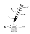
(3)シリンジ9を取り外し、図10に示されるように、容器52内の水の表面521に、シリンダ8内の生理食塩液とモンタナイドとの混合液を、デバイス1を通して滴下した。すなわち、所謂「ドロップテスト」を行った。
表1は、テスト結果を示している。テストは3回行った。

[テスト方法]
図1及び図10に示されるように、次の手順で行った。
(1)実施例12~14の場合には図1の調製器具100を用意し、実施例15の場合には図4の調製器具100を用意した。そして、シリンジ8に、分散相すなわち水相としての2%L-アルギニン水溶液を1.5ml充填し、シリンジ9に、連続相すなわち油相としてのモンタナイドを1.5ml充填した。なお、シリンジ8、9は、B BRAUN社製であり、容量5mlである。
(2)シリンジ8の押子82とシリンジ9の押子92とを交互に押すポンピング操作を手動で行い、それを5回繰り返した。これにより、両相を、シリンジ8内に収容した。
(3)シリンジ9を取り外し、図10に示されるように、容器52内の水の表面521に、シリンダ8内のL-アルギニン水溶液とモンタナイドとの混合液を、デバイス1を通して滴下した。すなわち、所謂「ドロップテスト」を行った。また、その際、デバイス1中の繊維32の脱落の有無も調べた。
表2は、テスト結果を示している。テストは2回行った。
[テスト方法]
図11に示されるように、次の手順で行った。
(1)図1の調製器具100を用意し、シリンジ8に、分散相すなわち水相としての2%L-アルギニン水溶液を1.5ml充填し、シリンジ9に、連続相すなわち油相としてのモンタナイドを1.5ml充填した。なお、シリンジ8、9は、B BRAUN社製であり、容量5mlである。
(2)シリンジ8の押子82とシリンジ9の押子92とを交互に手動でポンピング操作し、それを5回繰り返した。これにより、両相を、シリンジ8内に収容した。
(3)図11に示されるように、支持台551及びロードセル552を備えたオートグラフ装置55(型式:EZ-L-500N、島津製作所製)に、調製器具100を設置し、シリンジ8の押子82とシリンジ9の押子92とを交互に押す際の摺動抵抗値をロードセル552によって測定した。また、抵抗値としては、押子が5~15mmストロークする際の荷重の平均値を求めた。
なお、両シリンジ8、9の押子82、92の摺動速度は、500mm/分と1000mm/分とに設定した。
表3は、テスト結果を示している。押子82の摺動速度が500mm/分の場合には、テストを1回行い、1000mm/分の場合には、2回行った。

[テスト方法]
図11に示されるように、次の手順で行った。
(1)図1の調製器具100を用意し、シリンジ8に、分散相すなわち水相としての2%L-アルギニン水溶液を1.5ml充填し、シリンジ9に、連続相すなわち油相としてのモンタナイドを1.5ml充填した。なお、シリンジ8、9は、B BRAUN社製であり、容量5mlである。
(2)シリンジ8の押子82とシリンジ9の押子92とを交互に手動でポンピング操作し、それを5回繰り返した。これにより、両相を、シリンジ8内に収容した。
(3)図11に示されるように、支持台551及びロードセル552を備えたオートグラフ装置55(型式AG-500BR、島津製作所製)に、調製器具100を設置し、シリンジ8の押子82とシリンジ9の押子92とを交互に押す際の摺動抵抗値をロードセル552によって測定した。抵抗値は、ポンピング操作の1回目、2回目、3回目について測定した。また、抵抗値としては、押子が5~15mmストロークする際の荷重の平均値を求めた。なお、摺動速度は、500mm/分に設定した。
表4は、テスト結果を示している。

[テスト方法]
図11に示されるように、次の手順で行った。
(1)実施例12の場合には図1の調製器具100を用意し、実施例15の場合には図4の調製器具100を用意した。そして、シリンジ8に、分散相すなわち水相としての生理食塩水を1.5ml充填し、シリンジ9に、連続相すなわち油相としてのモンタナイドを1.5ml充填した。なお、シリンジ8、9は、B BRAUN社製であり、容量5mlである。
(2)シリンジ8の押子82とシリンジ9の押子92とを交互に手動でポンピング操作し、それを5回繰り返した。これにより、両相を、シリンジ8内に収容した。
(3)図11に示されるように、支持台551及びロードセル552を備えたオートグラフ装置55(型式AG-Xplus、島津製作所製)に、調製器具100を設置し、シリンジ8の押子82とシリンジ9の押子92とを交互に押す際の摺動抵抗値をロードセル552によって測定した。抵抗値は、ポンピング操作の1回目、2回目、3回目について測定した。また、抵抗値としては、押子が5~15mmストロークする際の荷重の平均値を求めた。なお、摺動速度は、500mm/分に設定した。
表5は、テスト結果を示している。

[テスト方法]
(1)図12は、実施例12のデバイス1についてのテストの様子を示している。なお、実施例15の場合は、デバイス1の代わりにデバイス1Aを使用した。デバイス1の一端に、0.8μmメンブレンフィルター61を介してガラスシリンジ62を取り付け、無塵の脱イオン水10mlを、フィルター61及びデバイス1を通して、清浄なガラス瓶63内に、勢い良く吐出した。これを全部で5回行った。次に、フィルター61及びシリンジ62を、取り外して、デバイス1の他端に同様に取り付けて、同じ操作を行った。これにより、ガラス瓶63内には約100mlの脱イオン水が回収された。この脱イオン水を検体とする。
表6は、実施例12についての結果を示しており、表7は、実施例15についての結果を示している。
Claims (12)
- フィルタ部を有している、エマルション調製用デバイスにおいて、
前記フィルタ部が、第1及び第2メッシュ部と繊維とによって、構成されており、
前記繊維が、第1メッシュ部と第2メッシュ部との間の空間内に充填されて繊維集合体を構成している、
ことを特徴とするエマルション調製用デバイス。 - 前記フィルタ部の一方の側又は両方の側が、シリンジに連結可能となっており、
前記フィルタ部の両方の側に連結された2つのシリンジの間を、又は、一方の側に連結されたシリンジと他方の側に連結された容器との間を、連続相と分散相とが前記フィルタ部を通って往復移動すると、エマルションを形成する、
請求項1記載のエマルション調製用デバイス。 - 前記第1メッシュ部及び/又は前記第2メッシュ部が円板である、
請求項1又は2に記載のエマルション調製用デバイス。 - 前記メッシュ部は、同心円状に均等に配置された円弧状の多数の貫通孔を有しており、全ての前記貫通孔は、10%の誤差範囲内で同じ面積を有している、
請求項3記載のエマルション調製用デバイス。 - 前記繊維が、疎水性繊維である、
請求項1~4のいずれか1つに記載のエマルション調製用デバイス。 - 前記疎水性繊維が、ポリエステルである、
請求項5記載のエマルション調製用デバイス。 - 前記繊維が、親水性繊維である、
請求項1~4のいずれか1つに記載のエマルション調製用デバイス。 - 前記繊維は、50~150デニールを有しており、前記空間1mm3当たり2.5~17.7mm存在するように充填されている、
請求項1~7のいずれか1つに記載のエマルション調製用デバイス。 - 前記繊維は、50~150デニールを有しており、前記空間1mm3当たり5.0~9.9mm存在するように充填されている、
請求項1~8のいずれか1つに記載のエマルション調製用デバイス。 - 第1円筒体と第2円筒体とからなっており、
前記第1円筒体は、第1円筒部と、前記第1円筒部に続く第2円筒部と、からなっており、
前記第2円筒部は、前記第1円筒部より小径であり、
前記第1円筒体において、前記第1円筒部と前記第2円筒部との境界には前記第1メッシュ部が形成されており、前記第1メッシュ部に向けて前記繊維が押し込まれており、前記繊維に向けて前記第2メッシュ部が押し付けられており、これにより、前記第1メッシュ部と前記繊維集合体と前記第2メッシュ部とからなる前記フィルタ部が構成されており、
前記第2メッシュ部は、前記第1円筒部に嵌合する凹形蓋の底面であり、
前記凹形蓋は、開口周縁の外フランジが前記第1円筒部の開口周縁に当接することによって、前記第2メッシュ部を、前記第1円筒部内において前記第1メッシュ部に対して所定距離に且つ平行に位置させており、
前記第1円筒体と前記第2円筒体とは、前記第1円筒部の前記開口周縁の外フランジと前記第2円筒体の開口周縁の外フランジとによって接合されて一体となっている、
請求項1~9のいずれか1つに記載のエマルション調製用デバイス。 - 第1円筒体と第2円筒体とからなっており、
前記第1円筒体は、第1円筒部と、前記第1円筒部に続く第2円筒部と、からなっており、
前記第2円筒部は、前記第1円筒部より小径であり、
前記第1円筒体において、前記第1円筒部と前記第2円筒部との境界には前記第1メッシュ部が形成されており、前記第1メッシュ部に向けて前記繊維が押し込まれており、前記繊維に向けて前記第2メッシュ部が押し付けられており、これにより、前記第1メッシュ部と前記繊維集合体と前記第2メッシュ部とからなる前記フィルタ部が構成されており、
前記第2メッシュ部は、前記第1円筒部に嵌合する凹形蓋の底面であり、
前記凹形蓋は、開口周縁の外フランジが前記第1円筒部の開口周縁に当接することによって、前記第2メッシュ部を、前記第1円筒部内において前記第1メッシュ部に対して所定距離に且つ平行に位置させており、
前記第1円筒体と前記第2円筒体とは、前記第1円筒部の前記開口周縁の外フランジと前記第2円筒体の開口周縁の外フランジとによって接合されて一体となっており、
前記繊維集合体が、長手方向の中央に位置しており、
前記第1円筒体と前記第2円筒体とが接合されて一体となった状態において、外部形状が長手方向において左右対称である、
請求項1~9のいずれか1つに記載のエマルション調製用デバイス。 - 請求項1~11のいずれか1つに記載のエマルション調製用デバイスを用いたことを特徴とする、エマルション調製方法。
Priority Applications (4)
| Application Number | Priority Date | Filing Date | Title |
|---|---|---|---|
| US14/379,877 US9770695B2 (en) | 2012-03-06 | 2013-03-04 | Emulsion preparation device and emulsion preparation method |
| CN201380012634.2A CN104159660B (zh) | 2012-03-06 | 2013-03-04 | 乳剂配制器件以及乳剂配制方法 |
| JP2014503833A JP6293656B2 (ja) | 2012-03-06 | 2013-03-04 | エマルション調製用デバイス及びエマルション調製方法 |
| EP13758680.6A EP2823879B1 (en) | 2012-03-06 | 2013-03-04 | Emulsion preparation device and emulsion preparation method |
Applications Claiming Priority (2)
| Application Number | Priority Date | Filing Date | Title |
|---|---|---|---|
| JP2012-049580 | 2012-03-06 | ||
| JP2012049580 | 2012-03-06 |
Publications (1)
| Publication Number | Publication Date |
|---|---|
| WO2013133209A1 true WO2013133209A1 (ja) | 2013-09-12 |
Family
ID=49116686
Family Applications (1)
| Application Number | Title | Priority Date | Filing Date |
|---|---|---|---|
| PCT/JP2013/055844 Ceased WO2013133209A1 (ja) | 2012-03-06 | 2013-03-04 | エマルション調製用デバイス及びエマルション調製方法 |
Country Status (6)
| Country | Link |
|---|---|
| US (1) | US9770695B2 (ja) |
| EP (1) | EP2823879B1 (ja) |
| JP (1) | JP6293656B2 (ja) |
| CN (1) | CN104159660B (ja) |
| TW (1) | TW201340959A (ja) |
| WO (1) | WO2013133209A1 (ja) |
Cited By (4)
| Publication number | Priority date | Publication date | Assignee | Title |
|---|---|---|---|---|
| JP2016059828A (ja) * | 2014-09-12 | 2016-04-25 | 柳衛 宏宣 | W/o/wエマルション製造装置 |
| JP2021062355A (ja) * | 2019-10-16 | 2021-04-22 | エス・ピー・ジーテクノ株式会社 | 円盤状多孔質膜ホルダー |
| WO2021117771A1 (ja) | 2019-12-10 | 2021-06-17 | 大日本住友製薬株式会社 | ペプチドエマルション製剤の調製方法 |
| JP2022075439A (ja) * | 2020-11-06 | 2022-05-18 | エス・ピー・ジーテクノ株式会社 | 二液混合デバイス |
Families Citing this family (2)
| Publication number | Priority date | Publication date | Assignee | Title |
|---|---|---|---|---|
| US10773222B1 (en) * | 2017-09-23 | 2020-09-15 | Graham Jeffrey Taylor | Extrusion apparatus |
| CN116240094B (zh) * | 2023-05-08 | 2023-08-04 | 北京纳通医疗科技控股有限公司 | 分离装置和svf的制备方法 |
Citations (8)
| Publication number | Priority date | Publication date | Assignee | Title |
|---|---|---|---|---|
| JPS5235235B2 (ja) | 1972-06-06 | 1977-09-08 | ||
| JPS5617623A (en) * | 1979-07-19 | 1981-02-19 | Exxon Research Engineering Co | Manufacture of emulsion using packing pipe emulsifying device |
| JPH09131519A (ja) * | 1995-10-09 | 1997-05-20 | Fuji Photo Film Co Ltd | 油滴型乳化物の送液系内分散方法及び該分散方法を使用する塗布方法 |
| JPH11509146A (ja) * | 1995-07-11 | 1999-08-17 | ビーメック グループ リミテッド | ポリマーフォームを製造するための装置および方法 |
| JP2005186026A (ja) | 2003-12-26 | 2005-07-14 | Spg Techno Kk | エマルション調製用デバイス及び方法 |
| JP2006346565A (ja) | 2005-06-15 | 2006-12-28 | Spg Techno Kk | 多孔質体を用いたエマルション生成方法とその装置 |
| JP2007083763A (ja) | 2005-09-20 | 2007-04-05 | Shin Caterpillar Mitsubishi Ltd | 遠隔管理システムの作業機械側動態データ管理装置 |
| JP2009148761A (ja) * | 2009-02-13 | 2009-07-09 | Galileo Co Ltd | ミキサー |
Family Cites Families (19)
| Publication number | Priority date | Publication date | Assignee | Title |
|---|---|---|---|---|
| US600953A (en) * | 1898-03-22 | Over lett | ||
| US2492037A (en) | 1945-05-08 | 1949-12-20 | Rockwood Sprinkler Co | Apparatus for generating foam |
| US4183681A (en) | 1978-05-19 | 1980-01-15 | Exxon Research & Engineering Co. | Emulsion preparation method using a packed tube emulsifier |
| DE3425078A1 (de) * | 1984-07-07 | 1986-02-06 | Bernhard 7913 Senden Holz | Einrichtung zum erzeugen von schaum |
| EP0285725B1 (en) * | 1987-04-10 | 1992-09-30 | Chugoku Kayaku Kabushiki Kaisha | Mixing apparatus |
| US4820276A (en) * | 1988-02-08 | 1989-04-11 | Enrique Moreno | Filter assembly for use with a hypodermic syringe |
| GB9620152D0 (en) * | 1996-09-27 | 1996-11-13 | Platt Kevin G | Improvements in or relating to the manufacture and use of aerated concrete |
| US6241220B1 (en) | 1997-01-10 | 2001-06-05 | Beamech Group Limited | Apparatus and process for producing polymeric foam |
| JP4335493B2 (ja) | 2002-03-08 | 2009-09-30 | 株式会社 タイヘイ機工 | 乳化分散液の製造方法 |
| EP1796602A4 (en) * | 2004-09-17 | 2016-10-19 | Angiotech Pharm Inc | MULTIFUNCTIONAL COMPOUNDS FOR PRODUCING NETWORKED BIOMATERIALS AND MANUFACTURING AND USE METHOD THEREFOR |
| DK1973475T3 (da) * | 2006-01-17 | 2010-10-18 | Baxter Int | Blandeindretning, -system og -fremgangsmåde |
| WO2007083763A1 (ja) | 2006-01-23 | 2007-07-26 | Greenpeptide Co., Ltd. | 生理活性ペプチドのエマルション製剤の調製方法、および当該製剤を調製するためのキット |
| US9656223B2 (en) * | 2008-06-16 | 2017-05-23 | Isel Co., Ltd. | Mixing unit and device, fluid mixing method and fluid |
| KR101853241B1 (ko) * | 2008-06-16 | 2018-06-04 | 아이세루 가부시키가이샤 | 혼합 요소, 혼합 장치, 교반날개, 혼합기, 혼합 시스템 및 반응 장치 |
| US8128591B2 (en) * | 2008-11-10 | 2012-03-06 | Warsaw Orthopedic, Inc. | Multiple component mixing and delivery system |
| US7621670B1 (en) * | 2009-02-25 | 2009-11-24 | The United States of America as represented by the National Aeronautica and Space Administration | Unbalanced-flow, fluid-mixing plug with metering capabilities |
| US8356927B1 (en) * | 2011-10-13 | 2013-01-22 | Angioletto Lordi | Universal hand mixer |
| US20130313281A1 (en) * | 2012-05-25 | 2013-11-28 | Restek Corporation | Method of dispensing analytic reference material |
| US8323490B1 (en) * | 2012-08-02 | 2012-12-04 | Instapure Brands, Inc. | Pressurized water filtration system |
-
2013
- 2013-03-04 JP JP2014503833A patent/JP6293656B2/ja active Active
- 2013-03-04 EP EP13758680.6A patent/EP2823879B1/en active Active
- 2013-03-04 US US14/379,877 patent/US9770695B2/en active Active
- 2013-03-04 WO PCT/JP2013/055844 patent/WO2013133209A1/ja not_active Ceased
- 2013-03-04 CN CN201380012634.2A patent/CN104159660B/zh active Active
- 2013-03-05 TW TW102107621A patent/TW201340959A/zh unknown
Patent Citations (8)
| Publication number | Priority date | Publication date | Assignee | Title |
|---|---|---|---|---|
| JPS5235235B2 (ja) | 1972-06-06 | 1977-09-08 | ||
| JPS5617623A (en) * | 1979-07-19 | 1981-02-19 | Exxon Research Engineering Co | Manufacture of emulsion using packing pipe emulsifying device |
| JPH11509146A (ja) * | 1995-07-11 | 1999-08-17 | ビーメック グループ リミテッド | ポリマーフォームを製造するための装置および方法 |
| JPH09131519A (ja) * | 1995-10-09 | 1997-05-20 | Fuji Photo Film Co Ltd | 油滴型乳化物の送液系内分散方法及び該分散方法を使用する塗布方法 |
| JP2005186026A (ja) | 2003-12-26 | 2005-07-14 | Spg Techno Kk | エマルション調製用デバイス及び方法 |
| JP2006346565A (ja) | 2005-06-15 | 2006-12-28 | Spg Techno Kk | 多孔質体を用いたエマルション生成方法とその装置 |
| JP2007083763A (ja) | 2005-09-20 | 2007-04-05 | Shin Caterpillar Mitsubishi Ltd | 遠隔管理システムの作業機械側動態データ管理装置 |
| JP2009148761A (ja) * | 2009-02-13 | 2009-07-09 | Galileo Co Ltd | ミキサー |
Non-Patent Citations (1)
| Title |
|---|
| "Insoluble Particulate Matter Test for Injections, Method 1. Light Obscuration Particle Count Test" |
Cited By (7)
| Publication number | Priority date | Publication date | Assignee | Title |
|---|---|---|---|---|
| JP2016059828A (ja) * | 2014-09-12 | 2016-04-25 | 柳衛 宏宣 | W/o/wエマルション製造装置 |
| JP2021062355A (ja) * | 2019-10-16 | 2021-04-22 | エス・ピー・ジーテクノ株式会社 | 円盤状多孔質膜ホルダー |
| JP7450146B2 (ja) | 2019-10-16 | 2024-03-15 | エス・ピー・ジーテクノ株式会社 | 円盤状多孔質膜ホルダー |
| WO2021117771A1 (ja) | 2019-12-10 | 2021-06-17 | 大日本住友製薬株式会社 | ペプチドエマルション製剤の調製方法 |
| KR20220113428A (ko) | 2019-12-10 | 2022-08-12 | 스미토모 파마 가부시키가이샤 | 펩티드 에멀션 제제의 조제 방법 |
| JP2022075439A (ja) * | 2020-11-06 | 2022-05-18 | エス・ピー・ジーテクノ株式会社 | 二液混合デバイス |
| JP7762842B2 (ja) | 2020-11-06 | 2025-10-31 | エス・ピー・ジーテクノ株式会社 | 二液混合デバイス |
Also Published As
| Publication number | Publication date |
|---|---|
| CN104159660B (zh) | 2016-05-11 |
| EP2823879A4 (en) | 2015-12-02 |
| JPWO2013133209A1 (ja) | 2015-07-30 |
| JP6293656B2 (ja) | 2018-03-14 |
| US20160214072A1 (en) | 2016-07-28 |
| CN104159660A (zh) | 2014-11-19 |
| EP2823879A1 (en) | 2015-01-14 |
| US9770695B2 (en) | 2017-09-26 |
| TW201340959A (zh) | 2013-10-16 |
| EP2823879B1 (en) | 2019-04-24 |
Similar Documents
| Publication | Publication Date | Title |
|---|---|---|
| JP6293656B2 (ja) | エマルション調製用デバイス及びエマルション調製方法 | |
| US9873098B2 (en) | Three-component mixing apparatus and three-component mixing adhesive kit | |
| DE4143394C2 (de) | Vorrichtung und Verfahren zum Trennen von Flüssigkeitsproben | |
| RU2462717C2 (ru) | Устройство и способ разделения и анализа крови | |
| DE102015116797B4 (de) | Vorrichtung und Verfahren zum Lagern und Mischen eines Knochenzements | |
| AU2015347309B2 (en) | Mechanical separator for a biological fluid | |
| CN1791800A (zh) | 红细胞沉降率(esr)试验测量仪的整体设计和方法 | |
| JP2019525177A (ja) | 自動臨床分析装置内で使用される試薬容器用の試薬組成物分注キャップ | |
| CN106366426A (zh) | 一种富血小板血浆提取和纯化的分离胶体系及其制备方法 | |
| EP1875225A1 (de) | Chromatographiesäule | |
| DE7804147U1 (de) | Filtervorrichtung | |
| JP6018252B2 (ja) | 生体液のための機械式分離器 | |
| CN212701671U (zh) | 一种儿内科抽血防凝固设备 | |
| US5076283A (en) | Method and apparatus for mixing of fluids | |
| CN208736874U (zh) | 适用于微量样品检测的试纸条检测卡及微量样品检测装置 | |
| CN210079562U (zh) | 一种perk磷酸化抗体用量滴管 | |
| CN108888296B (zh) | 一种自封式尿液采集装置 | |
| JP2018102659A (ja) | 血液成分吸着カラム | |
| CN217164135U (zh) | 一种大内科临床检查器 | |
| CN215606337U (zh) | 一种手术室护理用器械清点盒 | |
| US9096828B2 (en) | Method and device for separating charged particles in liquid sample and manufacturing method of the device | |
| CN224004791U (zh) | 微量全血样本采集管和血细胞分析仪 | |
| CN216117032U (zh) | 一种用于检验科医生的试剂检验装置 | |
| KR20050098872A (ko) | 피브리노겐 제거용 필터, 피브리노겐 제거용 필터 장치 및이들을 이용한 피브리노겐 제거 방법 | |
| Finkelstein | Design and evaluation of a new diagnostic instrument for osmotic gradient ektacytometrie |
Legal Events
| Date | Code | Title | Description |
|---|---|---|---|
| WWE | Wipo information: entry into national phase |
Ref document number: 201380012634.2 Country of ref document: CN |
|
| 121 | Ep: the epo has been informed by wipo that ep was designated in this application |
Ref document number: 13758680 Country of ref document: EP Kind code of ref document: A1 |
|
| WWE | Wipo information: entry into national phase |
Ref document number: 14379877 Country of ref document: US |
|
| ENP | Entry into the national phase |
Ref document number: 2014503833 Country of ref document: JP Kind code of ref document: A |
|
| NENP | Non-entry into the national phase |
Ref country code: DE |
|
| WWE | Wipo information: entry into national phase |
Ref document number: 2013758680 Country of ref document: EP |