WO2013133192A1 - プリコーディング装置、無線送信装置、無線受信装置、無線通信システムおよび集積回路 - Google Patents
プリコーディング装置、無線送信装置、無線受信装置、無線通信システムおよび集積回路 Download PDFInfo
- Publication number
- WO2013133192A1 WO2013133192A1 PCT/JP2013/055784 JP2013055784W WO2013133192A1 WO 2013133192 A1 WO2013133192 A1 WO 2013133192A1 JP 2013055784 W JP2013055784 W JP 2013055784W WO 2013133192 A1 WO2013133192 A1 WO 2013133192A1
- Authority
- WO
- WIPO (PCT)
- Prior art keywords
- precoding
- phase rotation
- signal
- wireless
- unit
- Prior art date
- Legal status (The legal status is an assumption and is not a legal conclusion. Google has not performed a legal analysis and makes no representation as to the accuracy of the status listed.)
- Ceased
Links
Images






Classifications
-
- H—ELECTRICITY
- H04—ELECTRIC COMMUNICATION TECHNIQUE
- H04L—TRANSMISSION OF DIGITAL INFORMATION, e.g. TELEGRAPHIC COMMUNICATION
- H04L5/00—Arrangements affording multiple use of the transmission path
- H04L5/003—Arrangements for allocating sub-channels of the transmission path
- H04L5/0048—Allocation of pilot signals, i.e. of signals known to the receiver
- H04L5/0051—Allocation of pilot signals, i.e. of signals known to the receiver of dedicated pilots, i.e. pilots destined for a single user or terminal
-
- H—ELECTRICITY
- H04—ELECTRIC COMMUNICATION TECHNIQUE
- H04B—TRANSMISSION
- H04B7/00—Radio transmission systems, i.e. using radiation field
- H04B7/02—Diversity systems; Multi-antenna system, i.e. transmission or reception using multiple antennas
- H04B7/04—Diversity systems; Multi-antenna system, i.e. transmission or reception using multiple antennas using two or more spaced independent antennas
- H04B7/0413—MIMO systems
- H04B7/0456—Selection of precoding matrices or codebooks, e.g. using matrices antenna weighting
-
- H—ELECTRICITY
- H04—ELECTRIC COMMUNICATION TECHNIQUE
- H04B—TRANSMISSION
- H04B7/00—Radio transmission systems, i.e. using radiation field
- H04B7/02—Diversity systems; Multi-antenna system, i.e. transmission or reception using multiple antennas
- H04B7/04—Diversity systems; Multi-antenna system, i.e. transmission or reception using multiple antennas using two or more spaced independent antennas
- H04B7/0413—MIMO systems
- H04B7/0452—Multi-user MIMO systems
-
- H—ELECTRICITY
- H04—ELECTRIC COMMUNICATION TECHNIQUE
- H04B—TRANSMISSION
- H04B7/00—Radio transmission systems, i.e. using radiation field
- H04B7/02—Diversity systems; Multi-antenna system, i.e. transmission or reception using multiple antennas
- H04B7/04—Diversity systems; Multi-antenna system, i.e. transmission or reception using multiple antennas using two or more spaced independent antennas
- H04B7/06—Diversity systems; Multi-antenna system, i.e. transmission or reception using multiple antennas using two or more spaced independent antennas at the transmitting station
- H04B7/0613—Diversity systems; Multi-antenna system, i.e. transmission or reception using multiple antennas using two or more spaced independent antennas at the transmitting station using simultaneous transmission
- H04B7/0615—Diversity systems; Multi-antenna system, i.e. transmission or reception using multiple antennas using two or more spaced independent antennas at the transmitting station using simultaneous transmission of weighted versions of same signal
- H04B7/0619—Diversity systems; Multi-antenna system, i.e. transmission or reception using multiple antennas using two or more spaced independent antennas at the transmitting station using simultaneous transmission of weighted versions of same signal using feedback from receiving side
-
- H—ELECTRICITY
- H04—ELECTRIC COMMUNICATION TECHNIQUE
- H04B—TRANSMISSION
- H04B7/00—Radio transmission systems, i.e. using radiation field
- H04B7/02—Diversity systems; Multi-antenna system, i.e. transmission or reception using multiple antennas
- H04B7/04—Diversity systems; Multi-antenna system, i.e. transmission or reception using multiple antennas using two or more spaced independent antennas
- H04B7/06—Diversity systems; Multi-antenna system, i.e. transmission or reception using multiple antennas using two or more spaced independent antennas at the transmitting station
- H04B7/0613—Diversity systems; Multi-antenna system, i.e. transmission or reception using multiple antennas using two or more spaced independent antennas at the transmitting station using simultaneous transmission
- H04B7/0682—Diversity systems; Multi-antenna system, i.e. transmission or reception using multiple antennas using two or more spaced independent antennas at the transmitting station using simultaneous transmission using phase diversity (e.g. phase sweeping)
-
- H—ELECTRICITY
- H04—ELECTRIC COMMUNICATION TECHNIQUE
- H04B—TRANSMISSION
- H04B7/00—Radio transmission systems, i.e. using radiation field
- H04B7/02—Diversity systems; Multi-antenna system, i.e. transmission or reception using multiple antennas
- H04B7/04—Diversity systems; Multi-antenna system, i.e. transmission or reception using multiple antennas using two or more spaced independent antennas
- H04B7/06—Diversity systems; Multi-antenna system, i.e. transmission or reception using multiple antennas using two or more spaced independent antennas at the transmitting station
- H04B7/0697—Diversity systems; Multi-antenna system, i.e. transmission or reception using multiple antennas using two or more spaced independent antennas at the transmitting station using spatial multiplexing
-
- H—ELECTRICITY
- H04—ELECTRIC COMMUNICATION TECHNIQUE
- H04B—TRANSMISSION
- H04B7/00—Radio transmission systems, i.e. using radiation field
- H04B7/02—Diversity systems; Multi-antenna system, i.e. transmission or reception using multiple antennas
- H04B7/04—Diversity systems; Multi-antenna system, i.e. transmission or reception using multiple antennas using two or more spaced independent antennas
- H04B7/08—Diversity systems; Multi-antenna system, i.e. transmission or reception using multiple antennas using two or more spaced independent antennas at the receiving station
- H04B7/0837—Diversity systems; Multi-antenna system, i.e. transmission or reception using multiple antennas using two or more spaced independent antennas at the receiving station using pre-detection combining
- H04B7/0842—Weighted combining
-
- H—ELECTRICITY
- H04—ELECTRIC COMMUNICATION TECHNIQUE
- H04J—MULTIPLEX COMMUNICATION
- H04J11/00—Orthogonal multiplex systems, e.g. using WALSH codes
- H04J11/0023—Interference mitigation or co-ordination
- H04J11/0026—Interference mitigation or co-ordination of multi-user interference
- H04J11/003—Interference mitigation or co-ordination of multi-user interference at the transmitter
- H04J11/0033—Interference mitigation or co-ordination of multi-user interference at the transmitter by pre-cancellation of known interference, e.g. using a matched filter, dirty paper coder or Thomlinson-Harashima precoder
-
- H—ELECTRICITY
- H04—ELECTRIC COMMUNICATION TECHNIQUE
- H04L—TRANSMISSION OF DIGITAL INFORMATION, e.g. TELEGRAPHIC COMMUNICATION
- H04L27/00—Modulated-carrier systems
- H04L27/32—Carrier systems characterised by combinations of two or more of the types covered by groups H04L27/02, H04L27/10, H04L27/18 or H04L27/26
- H04L27/34—Amplitude- and phase-modulated carrier systems, e.g. quadrature-amplitude modulated carrier systems
- H04L27/345—Modifications of the signal space to allow the transmission of additional information
- H04L27/3455—Modifications of the signal space to allow the transmission of additional information in order to facilitate carrier recovery at the receiver end, e.g. by transmitting a pilot or by using additional signal points to allow the detection of rotations
Definitions
- the present invention relates to wireless communication technology.
- MIMO Multiple input multiple output
- the amount of improvement in frequency utilization efficiency by the MIMO technology is proportional to the number of transmission / reception antennas.
- the number of receiving antennas that can be arranged in the terminal device is limited.
- Multi-User-MIMO MU-MIMO
- MU-MIMO Multi-User-MIMO
- MU-MIMO transmission signals destined for each terminal apparatus are received by the terminal apparatus as inter-user-interference (IUI), so it is necessary to suppress IUI.
- IUI inter-user-interference
- LTE long term evolution
- LTE long term evolution
- a linear filter calculated based on propagation path information notified from each terminal device is provided to the base station device.
- Linear precoding that suppresses IUI by multiplying in advance is adopted (hereinafter, MU-MIMO based on linear precoding is also referred to as linear MU-MIMO as a whole).
- 802.11ac which is being standardized as a next-generation wireless LAN system, the adoption of linear MU-MIMO is considered promising.
- MU-MIMO technology based on nonlinear precoding in which nonlinear signal processing is performed on the base station apparatus side is attracting attention (hereinafter referred to as nonlinear precoding).
- MU-MIMO based on this is also called non-linear MU-MIMO as a whole).
- the terminal device If the terminal device is capable of modulo operation, it can add a perturbation vector whose element is a complex number (perturbation term) obtained by multiplying an arbitrary Gaussian integer by a constant real number to the transmitted signal. It becomes.
- Non-Patent Document 1 describes Vector perturbation (VP) as a method that can realize optimal transmission characteristics as nonlinear precoding. While VP can achieve excellent transmission characteristics, the amount of computation increases exponentially in proportion to the number of spatially multiplexed terminals.
- THP Tomlinson Harashima precoding
- Nonlinear MU-MIMO is effective in improving the frequency utilization efficiency of MU-MIMO.
- Non-Patent Document 3 discusses hybrid THP that improves transmission characteristics by adaptively changing the application of modulo arithmetic for MU-MIMO transmission using THP. .
- the terminal apparatus selectively receives a signal that requires a modulo operation for demodulating the signal and a signal that does not require a modulo operation.
- a signal based on linear precoding and a signal based on nonlinear precoding are selectively received.
- Non-Patent Document 4 discusses newly notifying control information that explicitly indicates which precoding method is used. According to this method, the terminal apparatus can correctly grasp the applied precoding scheme, but there is a problem that the overhead is increased.
- the present invention has been made in view of such circumstances, and in a wireless communication system in which a plurality of precodings are selectively or simultaneously used, the terminal device performs any precoding without increasing overhead. It is an object of the present invention to provide a precoding device, a wireless transmission device, a wireless reception device, a wireless communication system, and an integrated circuit capable of grasping whether the transmission is performed.
- the precoding device of the present invention is a precoding device applied to a wireless transmission device that performs wireless communication with a wireless reception device, and based on control information acquired from the wireless reception device, a data signal and a plurality of types
- the unique reference signal is precoded, phase rotation is applied to each type of unique reference signal, and the amount of phase rotation of the phase rotation is associated with information to be notified to the radio reception apparatus.
- the precoding device performs precoding on the data signal and multiple types of unique reference signals based on the control information acquired from the wireless reception device, and applies phase rotation to each type of unique reference signal, thereby rotating the phase. Is associated with the information notified to the wireless reception device, so that it is possible for the wireless transmission device to transmit information bits using a part of DMRS. It can contribute to the improvement of frequency utilization efficiency.
- precoding is performed selectively or simultaneously using one of a plurality of types of precoding schemes for the data signal and a plurality of types of unique reference signals. And the phase rotation amount of the phase rotation indicates the precoding scheme used.
- phase rotation amount of the phase rotation indicates the precoding scheme used, precoding that is actually applied to the radio transmission apparatus in transmission that selectively uses linear precoding and non-linear precoding is used. Since the radio receiving apparatus can correctly grasp the method without notifying the method by the control information, a desired signal can be correctly demodulated from the received signal.
- the precoding device of the present invention when linear precoding is performed on the data signal, the first specific reference signal and the second specific reference signal are subjected to phase rotation of the same phase rotation amount.
- the first unique reference signal and the second unique reference signal are given different phase rotation amounts.
- the precoding apparatus performs linear precoding on the data signal
- the data signal is supplied to the first specific reference signal and the second specific reference signal with the same phase rotation amount.
- phase rotations of different phase rotation amounts are given to the first eigenreference signal and the second eigenreference signal, respectively, so that linear precoding and nonlinear precoding are selectively used.
- the wireless receiver can correctly grasp the precoding method actually applied by the wireless transmitter without using control information, so the desired signal can be correctly demodulated from the received signal. It becomes possible to do.
- the wireless transmission device of the present invention includes the precoding device according to any one of (1) to (3) above and a plurality of transmission antennas, and each of the plurality of wireless reception devices.
- Precoding is performed to suppress interference observed in the wireless reception device, and a part of the data signal transmitted to the plurality of wireless reception devices is spatially multiplexed with the same wireless resource. It is characterized by transmitting.
- the wireless transmission device is a wireless reception device based on control information notified from a plurality of wireless reception devices with respect to a part of data signals and unique reference signals transmitted to the plurality of wireless reception devices.
- Precoding that suppresses observed interference is performed, and a part of the data signal transmitted to a plurality of radio reception apparatuses is spatially multiplexed with the same radio resource, so that in the case of MU-MIMO transmission, Since it becomes possible to add a new precoding method while maintaining compatibility, it is possible to contribute to the advancement of the radio communication system, and thus to improve the frequency utilization efficiency.
- the wireless reception device of the present invention is a wireless reception device that performs wireless communication with a wireless transmission device, and notifies the wireless transmission device of control information, and the wireless transmission device notifies the notification.
- Receiving a pre-coded data signal addressed to its own device based on the control information and a plurality of types of unique reference signals, extracting the phase rotation amount of the phase rotation given to each type of unique reference signal, and extracting It is characterized by acquiring information associated with the phase rotation amount.
- the wireless reception device extracts the phase rotation amount of the phase rotation given to each type of unique reference signal, and acquires information associated with the extracted phase rotation amount. Since it is possible to transmit information bits by a part of DMRS, it is possible to contribute to further improvement of frequency utilization efficiency in MIMO transmission in which precoding is performed.
- the data signal and the plurality of types of unique reference signals may be precoded selectively or simultaneously using any one of a plurality of types of precoding schemes.
- the precoding scheme used is recognized based on the phase rotation amount, and the received data signal is demodulated.
- the radio transmission apparatus is actually used. Since the radio receiving apparatus can correctly grasp the precoding method applied to the control signal without using the control information, a desired signal can be correctly demodulated from the received signal.
- the data signal is linear. If it is determined that precoding has been performed, and if the first specific reference signal and the second specific reference signal have been subjected to phase rotation of different phase rotation amounts, a nonlinear precoding is performed on the data signal. It is determined that coding has been performed, and the received data signal is demodulated.
- the wireless receiver when the wireless receiver receives the same phase rotation amount for the first unique reference signal and the second unique reference signal, linear precoding is performed on the data signal.
- the first unique reference signal and the second unique reference signal are subjected to phase rotation of different phase rotation amounts, nonlinear precoding is applied to the data signal. Therefore, in the transmission that selectively uses the linear precoding and the non-linear precoding, the radio reception apparatus correctly grasps the precoding method that is actually applied by the radio transmission apparatus without reporting the control information. Therefore, the desired signal can be correctly demodulated from the received signal.
- the received data signal is subjected to nonlinear precoding regardless of the determination of the precoding scheme based on the phase rotation amount. Is demodulated.
- the wireless reception device demodulates the data signal assuming that non-linear precoding is applied to the received data signal regardless of the determination of the precoding scheme based on the amount of phase rotation. Transmission characteristics can be obtained.
- the wireless reception device of the present invention is characterized in that, when nonlinear precoding is applied to the received data signal, nonlinear processing including modulo calculation is performed.
- the wireless reception device when the wireless reception device performs nonlinear precoding on the received data signal, nonlinear processing including modulo operation is performed, and therefore linear precoding and nonlinear precoding are selectively performed.
- the wireless reception device since the wireless reception device can correctly grasp the precoding method actually applied by the wireless transmission device without using the control information, a desired signal is obtained from the received signal. It becomes possible to demodulate correctly.
- the wireless communication system of the present invention includes the wireless transmission device according to (4) above and the wireless reception device according to any of (5) to (9) above. It is said.
- the wireless communication system includes the wireless transmission device described in (4) above and the wireless reception device described in any of (5) to (9) above, one wireless transmission device is included. Since it is possible to transmit information bits by a part of DMRS, it is possible to contribute to further improvement of frequency utilization efficiency in MIMO transmission in which precoding is performed.
- An integrated circuit according to the present invention is an integrated circuit that is mounted on a wireless transmission device that performs wireless communication with a wireless reception device, and that allows the wireless transmission device to perform a plurality of functions, and is controlled by the wireless reception device. Based on the control information and a function for obtaining information, either a linear precoding scheme or a non-linear precoding scheme is selectively or simultaneously used for a data signal and a plurality of types of unique reference signals.
- the first unique reference signal and the second unique reference signal are given phase rotation of the same phase rotation amount, while the data signal When nonlinear precoding is applied to the signal, the first unique reference signal and the second unique reference signal are different. That has a function of giving a phase rotation of the phase rotation amount, at least, the phase rotation amount of said phase rotation, is characterized by showing a precoding scheme used above.
- the radio transmission apparatus performs linear precoding on the data signal
- the data signal is supplied while the first unique reference signal and the second unique reference signal are given the same phase rotation amount.
- phase rotations of different phase rotation amounts are given to the first eigenreference signal and the second eigenreference signal, respectively, so that linear precoding and nonlinear precoding are selectively used.
- the wireless receiver can correctly grasp the precoding method actually applied by the wireless transmitter without using control information, so the desired signal can be correctly demodulated from the received signal. It becomes possible to do.
- An integrated circuit is an integrated circuit that is mounted on a wireless reception device that performs wireless communication with a wireless transmission device, and that allows the wireless reception device to perform a plurality of functions.
- a function for notifying control information, and a data signal addressed to the own device that has been linearly or non-linearly precoded based on the notified control information, a first unique reference signal, and a second A function of receiving a unique reference signal and linear precoding for the data signal when the first unique reference signal and the second unique reference signal have the same phase rotation amount
- the first specific reference signal and the second specific reference signal are subjected to phase rotations of different phase rotation amounts.
- the data signal has at least a function of determining that nonlinear precoding is applied to the data signal and a function of demodulating the received data signal based on the result of the determination. .
- the wireless receiver when the wireless receiver receives the same phase rotation amount for the first unique reference signal and the second unique reference signal, linear precoding is performed on the data signal.
- the first unique reference signal and the second unique reference signal are subjected to phase rotation of different phase rotation amounts, nonlinear precoding is applied to the data signal. Therefore, in the transmission that selectively uses the linear precoding and the non-linear precoding, the radio reception apparatus correctly grasps the precoding method that is actually applied by the radio transmission apparatus without reporting the control information. Therefore, the desired signal can be correctly demodulated from the received signal.
- a plurality of precoding can be used selectively or simultaneously without increasing overhead. Therefore, since a new precoding scheme can be added to a system in which a specific precoding scheme has already been standardized, it can contribute to the improvement of the frequency utilization efficiency of the system.
- AT is a transposed matrix of matrix A
- a H is an adjoint (Hermitian transposed) matrix of matrix A
- a -1 is an inverse matrix of matrix A
- a + is a pseudo (or general) inverse matrix of matrix A
- diag (A) is a diagonal matrix obtained by extracting only the diagonal components of the matrix A.
- floor (c) is a floor that returns the largest Gaussian integer whose real part and imaginary part do not exceed the values of the real part and imaginary part of the complex number c, respectively.
- E [x] is the ensemble average of the random variable x
- abs (c) is a function that returns the amplitude of the complex number c
- angle (c) is a function that returns the argument of the complex number c
- Norm and x% y represent the remainder when integer x is divided by integer y.
- [A; B] represents a matrix obtained by combining the two matrices A and B in the row direction, and [A, B] represents a matrix coupled in the column direction.
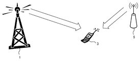
- FIG. 1 is a diagram showing an outline of a radio communication system according to the first embodiment of the present invention.
- one terminal device also referred to as a wireless reception device
- a base station device also referred to as a wireless transmission device
- the terminal device 3 assumes an environment where a signal (desired signal or desired signal) transmitted from the base station device 1 and an interference signal transmitted from the interference source 5 are received.
- the interference signal refers to a signal different from the desired signal, which is transmitted using the same radio resource as the desired signal.
- the same frequency interference (or inter-cell interference) in a cellular system that performs frequency repetition is applicable.
- OFDM orthogonal frequency division multiplexing
- the base station apparatus 1 acquires information on an interference signal received by the terminal apparatus 3 based on the control information notified from the terminal apparatus 3, and performs precoding for each subcarrier on transmission data based on the interference signal information.
- the base station apparatus 1 and the terminal apparatus 3 are each provided with one antenna, and the propagation path between the base station apparatus 1 and the terminal apparatus 3 takes into account only thermal noise applied in the terminal apparatus 3. It is assumed that this is an AWGN channel.
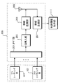
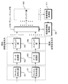
- FIG. 2 is a block diagram showing a configuration of the base station apparatus 1 according to the first embodiment of the present invention.
- the base station apparatus 1 includes a channel coding unit 101, a data modulation unit 103, a mapping unit 105, a precoding unit 107A (hereinafter referred to as precoding units 107A, 107B, 107C,... Are also represented as a precoding unit 107), an antenna unit 109, a control information acquisition unit 111, and an interference information acquisition unit 113.
- precoding units 107A hereinafter referred to as precoding units 107A, 107B, 107C,... Are also represented as a precoding unit 107
- an antenna unit 109 There are as many precoding units 107A as the number of subcarriers Nc .
- the transmission data sequence addressed to the terminal device 3 is subjected to channel coding in the channel coding unit 101 and then subjected to digital data modulation such as QPSK and 16QAM in the data modulation unit 103.
- An output from the data modulation unit 103 is input to the mapping unit 105.
- the mapping unit 105 performs mapping (also referred to as scheduling or resource allocation) in which each data is allocated to a designated radio resource (also referred to as resource element or simply resource).
- the radio resource here mainly refers to frequency and time.
- the radio resource to be used is determined based on reception quality or the like observed by the terminal device 3. In the present embodiment, it is assumed that radio resources to be used are determined in advance and can be grasped by both the base station device 1 and the terminal device 3.
- mapping section 105 a known reference signal sequence for performing propagation path estimation in terminal apparatus 3 is also multiplexed.
- the reference signals addressed to the terminal device 3 are multiplexed so as to be orthogonal to each other so that the received terminal device 3 can be separated from the data signal.
- the demodulation reference signal which is a specific reference signal for demodulation
- another reference signal may be further multiplexed. It is assumed that DMRS is periodically transmitted for each of time and frequency resources.
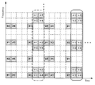
- FIG. 3 is a diagram showing an example of resource allocation of DMRS and data signal in the first embodiment of the present invention.
- the horizontal axis represents time (OFDM signal number), and the vertical axis represents frequency (subcarrier number).
- FIG. 3 shows a part of all radio resources, it can be considered that this arrangement is repeated in the time and frequency directions.
- a DMRS is transmitted in a resource qualified by a network line, but a DMRS surrounded by a broken line (hereinafter referred to as a second DMRS) is a DMRS surrounded by a solid line (hereinafter referred to as a first DMRS).
- phase rotation according to a precoding method to be described later is performed. Details will be described later.
- the output of the mapping unit 105 is input to the corresponding subcarrier precoding unit 107A.
- the signal processing in the precoding unit 107A will be described later. In the following, signal processing for the output of the precoding unit 107A will be described first.
- the output of the precoding unit 107A for each subcarrier is input to the antenna unit 109 of the corresponding transmission antenna.
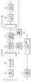
- FIG. 4 is a block diagram showing a device configuration of the antenna unit 109 according to the first embodiment of the present invention.
- the antenna unit 109 includes an IFFT unit 201, a GI insertion unit 203, a wireless transmission unit 205, a wireless reception unit 207, and an antenna 209.
- the output of the corresponding precoding unit 107A is input to the IFFT unit 201, and an Nc- point inverse fast Fourier transform (IFFT) or inverse discrete Fourier transform (IDFT) is applied to the Nc sub.
- IFFT inverse fast Fourier transform
- IDFT inverse discrete Fourier transform
- the output of the IFFT unit 201 is input to the GI insertion unit 203, and after being given a guard interval, is input to the wireless transmission unit 205.
- the wireless transmission unit 205 the baseband transmission signal is converted into a radio frequency (Radio Frequency (RF)) transmission signal.
- RF Radio Frequency
- the wireless reception unit 207 receives information associated with the interference signal estimated by the terminal device 3 and outputs the information to the control information acquisition unit 111.
- Precoding unit 107A Signal processing performed in precoding section 107A will be described. In the following, the k-th subcarrier precoding unit 107A will be described, and first, the case where the data signal component of the output of the mapping unit 105 is input will be described.
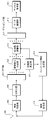
- FIG. 5 is a block diagram showing a device configuration of the precoding unit 107A according to the first embodiment of the present invention.
- the precoding unit 107A includes an interference suppression unit 301, a modulo calculation unit 303, a precoding switching unit 305, a switch 307A, a switch 307B, and a DMRS phase control unit 309.
- the precoding unit 107A includes the k-th subcarrier component ⁇ d (k) ⁇ of the output of the mapping unit 105 including transmission data addressed to the terminal device 3, and the interference signal ⁇ i (k) ⁇ received by the terminal device 3. Is entered.
- the interference signal ⁇ i (k) ⁇ is ideally acquired by the interference information acquisition unit 113, and the index k is omitted for simplicity.
- d-i. P x will change according to the interference signal i.
- P x is larger than a predetermined threshold value
- the switch 307A and the switch 307B are controlled so that the interference suppression unit 301 outputs the transmission code x toward the modulo arithmetic unit 303.
- P x is smaller than the threshold value, the switches 307A and 307B are controlled so that the transmission signal s is output from the interference suppression unit 301 toward the antenna unit 109.
- the threshold value can be determined in advance by computer simulation or the like.
- information regarding how the switch is switched is input to the DMRS phase control unit 309.
- the modulo operation unit 303 When the transmission code x is input to the modulo operation unit 303 from the precoding switching unit 305, the modulo operation unit 303 performs a modulo operation with a modulo width ⁇ on the transmission code x.
- Modulo operation mod ⁇ (x) with a modulo width ⁇ is a complex number in which the real part and the imaginary part are larger than ⁇ and smaller than ⁇ by adding an arbitrary Gaussian integer to an arbitrary input complex number x. Is an operation that returns. When expressed by an equation, it is expressed by equation (1).
- the average power of the modulo calculation output represented by the equation (1) is (2/3) ⁇ ⁇ 2 with respect to the average power of the original transmission data, a constant average is obtained regardless of the value of the interference power.
- ⁇ is not limited to anything as long as it is shared by the base station apparatus 1 and the terminal apparatus 3, but normally, the average bit value is the highest for a given transmission power.
- a value that reduces the error rate (Bit Error Rate (BER)) is selected. The value depends on the data modulation method applied to d, and is set to 2 1/2 for QPSK modulation and 4 ⁇ 10 ⁇ 1/2 for 16QAM, for example.
- BER Bit Error Rate
- the precoding switching unit 305 switches between linear precoding and nonlinear precoding based on the input transmission code power.
- the output of the modulo calculation unit 303 or the output of the interference suppression unit 301 is output toward the antenna unit 109 as the output of the precoding unit 107A.
- Pre-coding may be switched for each radio resource, but since the terminal device 3 needs to know which pre-coding has been performed, it is not desirable to switch the pre-coding in a very short cycle.
- precoding is switched in units of resource blocks (Resource block (RB)) in which 168 radio resources composed of 12 subcarriers included in the 14 OFDM symbols shown in FIG.
- RB resource block
- the number of resources included in the RB is not limited to this.
- Whether linear precoding or non-linear precoding is used is determined according to the power of the interference signal. If the interference signal varies in the time or frequency direction, the precoding scheme will also change in the time or frequency direction. In the applied precoding scheme, the signal demodulation method of the terminal device 3 to be described later changes, so the terminal device 3 needs to know which precoding is performed. Therefore, in the present embodiment, the terminal device 3 can grasp which precoding scheme is applied by changing the phase of the signal sequence used for the DMRS transmitted to the terminal device 3.
- DMRS Downlink Reference Signal
- the signal series used according to the pre-coding system applied to a data signal component is changed.
- the DMRS phase control unit 309 determines the amount of phase rotation to be given to the second DMRS based on the information about the precoding scheme applied to the transmission data input from the precoding switching unit 305, and interferes with the information. Input to the suppression unit 301.
- the interference suppression unit 301 performs phase rotation on the second DMRS based on information input from the DMRS phase control unit 309.
- the precoding method is linear precoding
- CDMRS is used as it is as a signal sequence.
- the signal sequence is a sequence obtained by applying phase rotation to CDMRS by ⁇ ⁇ c 1 , ⁇ c 2 , c 3 , ⁇ c 4 . . .
- C Np ⁇ may be used as a signal sequence.
- the phase rotation amount is ⁇ , but any phase rotation amount may be used as long as both the base station device 1 and the terminal device 3 are known.
- the signal sequence length may be an arbitrary length.
- the DMRS is for estimating information (propagation path information) for the terminal device 3 to demodulate a desired signal from a received signal.
- the information that the terminal device 3 wants to estimate is a power normalization term multiplied by the transmission signal. Therefore, if the DMRS that is a known signal is subjected to the same interference suppression processing as the data signal in the precoding unit 107A, the terminal device 3 can estimate the power normalization term.
- the precoding switching unit 305 determines whether or not to apply phase rotation to the CDMRS . However, when nonlinear precoding is performed, a modulo operation is also performed on DMRS.
- the power normalization term cannot be correctly estimated. Therefore, DMRS is transmitted by linear precoding even if non-linear precoding is applied to the data signal. At this time, since the power normalization term needs to be the same as that of the data signal, the transmission power of the DMRS slightly increases as compared with the data signal. In addition, if the terminal device 3 can correctly estimate the perturbation term added to the DMRS by another method, the DMRS may be subjected to nonlinear precoding.
- the ratio of the first DMRS and the second DMRS in the total radio resources is the same, but the ratio of the two does not necessarily have to be common.
- power normalization is not necessarily performed for each radio resource, and normalization may be performed such that the average transmission power for each of a plurality of radio resources (for example, every 1 RB) is constant.
- FIG. 6 is a block diagram showing a configuration of the terminal device 3 according to the first embodiment of the present invention.
- the terminal device 3 includes an antenna 401, a radio reception unit 403, a GI removal unit 405, an FFT unit 407, a reference signal separation unit 409, a propagation path estimation unit 411, and a feedback information generation unit. 413, a wireless transmission unit 414, a propagation path compensation unit 415, a demapping unit 417, a data demodulation unit 419, and a channel decoding unit 421.
- a signal received by the antenna 401 is input to the wireless reception unit 403 and converted into a baseband signal.
- the signal converted into the baseband is input to the GI removal unit 405, and after the guard interval is removed, is input to the FFT unit 407.
- N c point fast Fourier transform (FFT) or discrete Fourier transform (DFT) is applied to the input signal to convert it into N c subcarrier components.
- the output of the FFT unit 407 is input to the reference signal separation unit 409.
- the reference signal separation unit 409 separates the input signal into a data signal component and a DMRS component.
- the data signal component is output toward the propagation path compensation unit 415, and the DMRS is output toward the propagation path estimation unit 411.
- the signal processing described below is basically performed for each subcarrier.
- the propagation path estimation unit 411 performs propagation path estimation based on the input DMRS that is a known reference signal, and also estimates the precoding scheme currently applied by the base station apparatus 1.
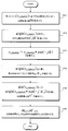
- FIG. 7 is a flowchart for explaining signal processing for DMRS in the propagation path estimation unit 411 according to the first embodiment of the present invention. Below, the signal processing with respect to DMRS is demonstrated based on the flowchart as described in FIG.
- the propagation path estimation unit 411 first performs propagation path estimation based on the first DMRS (step S101). Since the DM DMRS is used as the signal sequence for the first DMRS, the channel information H can be estimated by performing inverse modulation with the CDMRS .
- the propagation path estimation unit 411 performs inverse modulation on the radio resource in which the second DMRS is received based on the respective sequences, and performs two propagation path estimation values H LP and H NLP .
- a propagation path estimated value is calculated (step S102 and step S103).
- the information representing the error may be any information, but for example, the square error between H LP and H may be calculated.
- a mean square error between H LP and H estimated in plural may be calculated.
- step S105: YES it is determined that the precoding scheme used is linear precoding; otherwise (step S105: NO), the precoding scheme is Judge as non-linear precoding.
- the propagation path information estimated by the first and second DMRSs and the estimation result of the precoding scheme are output to the propagation path compensation section 415 as the output of the propagation path estimation section 411.
- Step S106 and Step S107 For example, when it is determined that the precoding is linear, the final channel estimation value is output using H and HLP . What averaged both may be sufficient, and what is necessary is just to output the result of applying some kind of interpolation. If it is determined that the precoding is nonlinear, the final channel estimation value is output from H and H NLP .
- the channel estimation unit 411 when the reception power is extremely small and, if the calculated error (the difference between the delta LP and delta NLP) is extremely small, the estimation accuracy of the precoding scheme, becomes extremely poor. Therefore, when the difference between the advance than determined threshold and delta LP delta NLP is small, the channel estimation unit 411, a precoding scheme applied to the data signal be determined that is a non-linear precoding good. As already described, if the terminal device 3 does not demodulate the signal by an appropriate demodulation method determined for each precoding scheme, the transmission characteristics are degraded.
- the amount of degradation in transmission characteristics when a signal with linear precoding is demodulated as a signal with nonlinear precoding is demodulated by assuming that a signal with nonlinear precoding has been subjected to linear precoding. This is smaller than the amount of degradation of transmission characteristics. Therefore, when the precoding scheme estimation accuracy is extremely poor, more stable transmission characteristics can be obtained by performing signal demodulation assuming that nonlinear precoding is always performed.
- the propagation path estimation unit 411 also performs interference signal estimation.
- a part of radio resources (carrier holes) that do not transmit any signal from the base station apparatus 1 are set, or a known reference signal that is not precoded separately from the DMRS is transmitted. It is possible to estimate.
- the estimated interference signal is output to feedback information generation section 413 and converted into a signal that can be reported to base station apparatus 1.
- the estimated interference signal may be quantized with a finite number of bits, or the estimated interference signal may be transmitted as it is as a transmission signal.
- the output of the feedback information generation unit 413 is sent to the radio transmission unit 414 and finally transmitted to the base station apparatus 1.
- the above is signal processing in the propagation path estimation unit 411.
- the data signal component, the channel estimation value estimated by the channel estimation unit 411, and the precoding scheme estimation value are input to the channel compensation unit 415.
- the channel compensation unit 415 first performs channel equalization processing using the channel estimation value.
- the channel equalization process may be performed by simple synchronous detection that divides the propagation path estimated value from the received signal. After the channel equalization processing is performed, signal processing based on the precoding scheme estimation result is performed.
- the channel equalized signal is output as it is to the demapping unit 417 as the output of the propagation path compensation unit 415.
- a modulo operation with the same modulo width as the modulo operation performed by the precoding unit 107A of the base station apparatus 1 is performed on the channel equalized signal.
- the modulo calculation result is output to the demapping unit 417 as the output of the propagation path compensation unit 415.
- the terminal device 3 extracts transmission data addressed to itself from radio resources used for transmission of transmission data addressed to itself.
- the output of the reference signal separation unit 409 may be input to the demapping unit 417 first, and only the radio resource component corresponding to the own device may be input to the propagation path compensation unit 415.
- the output of demapping section 417 is then input to data demodulating section 419 and channel decoding section 421, where data demodulation and channel decoding are performed.
- the propagation path estimation unit 411 estimates that the nonlinear precoding is performed in the base station apparatus 1, the propagation path compensation unit 415 does not perform the modulo operation, and which of the precoding methods is used. Is input to the channel decoding unit 421.
- the channel decoding unit 421 may determine the channel decoding method based on the precoding method estimation result.
- OFDM signal transmission is performed and precoding is performed for each subcarrier, but there is no limitation on the transmission scheme (or access scheme) and the precoding application unit.
- the present embodiment is also applicable when precoding is performed for each resource block in which a plurality of subcarriers are grouped.
- a single carrier-based access scheme for example, single carrier frequency division multiple access (SC- (FDMA) method.
- the terminal apparatus 3 can correctly grasp the precoding method that is actually applied without notifying the control information. Therefore, it is possible to correctly demodulate a desired signal from the received signal.
- the base station device 1 and the terminal device 3 are each targeted for one-to-one transmission.
- the second embodiment is directed to multi-user MIMO (MU-MIMO) transmission in which a base station apparatus having a plurality of transmission antennas and a plurality of terminal apparatuses perform simultaneous communication using the same radio resource.
- MU-MIMO multi-user MIMO
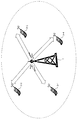
- FIG. 8 is a diagram showing an outline of a radio communication system according to the second embodiment of the present invention.
- a terminal apparatus that has N t transmitting antennas and has one receiving antenna for a base station apparatus (radio transmitting apparatus) 1 that can perform linear precoding and nonlinear precoding.
- the base station apparatus 1 acquires propagation path information to each terminal apparatus 3 from the control information notified from each terminal apparatus 3, and performs precoding for each subcarrier on transmission data based on the propagation path information.
- the number of reception antennas of the terminal device 3 is not limited to one.
- the number of data streams (also referred to as the rank number) transmitted to each terminal apparatus 3 is 1.
- the present embodiment includes a case where the rank number is 2 or more.
- CSI Channel State Information
- a quasi-static frequency selective fading channel is assumed.
- FIG. 9 is a block diagram showing a configuration of the base station apparatus 1 according to the second embodiment of the present invention.
- the base station apparatus 1 includes a channel encoding unit 101, a data modulation unit 103, a mapping unit 105, a precoding unit 107B, an antenna unit 109, a control information acquisition unit 111, a propagation path An information acquisition unit 501 is included.
- Precoding section 107B exists for the number of subcarriers N c
- antenna section 109 exists for the number of transmission antennas N t .
- the transmission data sequence addressed to each terminal apparatus 3 is subjected to channel coding in channel coding section 101 and then subjected to digital data modulation such as QPSK and 16QAM in data modulation section 103.
- An output from the data modulation unit 103 is input to the mapping unit 105.
- the mapping unit 105 similarly to the first embodiment, the transmission data and the unique reference signal are respectively mapped to appropriate radio resources.
- the mapping unit 105 is directed to a plurality of terminal devices 3.
- DMRS unique reference signal
- CRS Cell-specific reference signal
- CRS is a reference signal that is basically transmitted without precoding.
- such a reference signal is also referred to as a sounding signal).
- the method for multiplexing CRS and DMRS is not particularly limited.
- the CRS is arranged so as to be orthogonal between the transmission antennas
- the DMRS is arranged so as to be orthogonal between the connected terminal apparatuses 3.
- any of time orthogonal, frequency orthogonal, spatial orthogonal, code orthogonal, or a combination of a plurality of orthogonal techniques can be considered.
- the data signal and the reference signal are assumed to be orthogonal to each other in time and frequency, and the terminal device 3 will be described assuming that desired information can be ideally estimated.
- the DMRS addressed to the u-th terminal device 3-u is originally intended to estimate information meaningful only to the u-th terminal device 3-u.
- the other terminal device 3 can grasp the DMRS addressed to the u-th terminal device 3-u.
- the terminal device 3 can perform IUI suppression processing such as an interference canceller in a propagation path compensation unit described later.
- IUI suppression processing such as an interference canceller in a propagation path compensation unit described later.
- detailed description of the interference canceller is omitted.
- the phase rotation given to the signal sequence is changed according to the precoding method described later. Details will be described later.
- the output of the mapping unit 105 is input to the corresponding subcarrier precoding unit 107B.
- the signal processing in the precoding unit 107B will be described later.
- the signal processing for the output of the precoding unit 107B will be described first.
- the output of precoding section 107B for each subcarrier is input to antenna section 109 of the corresponding transmission antenna.
- the device configuration of the antenna unit 109 according to the present embodiment is the same as the device configuration shown in FIG. 4 and the signal processing being performed is substantially the same, and thus the description thereof is omitted.
- a plurality of antenna units 109 exist, and what is output toward the control information acquisition unit 111 is not information associated with the interference signal, but is expressed by Equation (2).
- the information associated with the given propagation path information is different from the antenna unit 109 of the first embodiment.
- FIG. 11 is a block diagram showing a device configuration of the precoding unit 107B according to the second embodiment of the present invention.
- the precoding unit 107B includes a linear filter generation unit 601, a precoding switching unit 603, a perturbation vector search unit 605, a transmission signal generation unit 607, and a DMRS phase control unit 609. It is configured. First, signal processing when a data signal is input to the precoding unit 107B will be described.
- the k-th subcarrier component ⁇ d u (k); u 1 to U ⁇ of the output of the mapping unit 105 including the transmission data addressed to each terminal device 3 and the k-th output of the propagation path information acquisition unit 501
- a subcarrier propagation path matrix H (k) is input.
- H (k) is estimated by the terminal device 3 based on the above-described CRS and notified to the base station device 1. In the following description, it is assumed that H (k) is ideally acquired by the propagation path information acquisition unit 501, and the index k is omitted for simplicity.
- the precoding unit 107B calculates a linear filter W for suppressing IUI.
- the calculation method of W is not limited to anything.
- a linear filter based on zero forcing (ZF) that completely suppresses IUI may be calculated.
- IAI inter-antenna interference
- a linear filter that suppresses both IUI and IAI, or a linear filter that suppresses only IUI or only IAI may be used.
- the perturbation vector search unit 605 searches for a perturbation term.
- the perturbation term search method is determined in accordance with the desired transmission quality and the amount of computation that can be realized by the arithmetic unit included in the base station apparatus 1. For example, when using Vector perturbation (VP) that can achieve the highest reception quality, the perturbation term can be obtained by solving the minimization problem expressed by Equation (3).
- VP Vector perturbation
- z t [z t, 1 ,. . . , Z t, U ] T
- z t, u is a perturbation term added to the transmission data addressed to the u th terminal apparatus 3-u.
- Equation (3) assumes a case where all the terminal devices 3 connected to the base station device 1 can perform a modulo calculation. However, in an actual system, there may be a mixture of terminals that support the modulo operation and terminals that do not support it. Adding the perturbation term is effective for maximizing the channel capacity of the entire system, but may not necessarily maximize the channel capacity that each terminal device 3 can achieve. For example, in an environment where the data modulation method is QPSK and the received signal-to-noise power ratio (SNR) is relatively small, it is better not to add the perturbation term. It is reported that it can be taken. In other words, it is more effective in improving the frequency utilization efficiency to control not to add the perturbation term to some transmission data without adding the perturbation term to all the transmission data addressed to each terminal device 3. It means that there may be.
- SNR received signal-to-noise power ratio
- the precoding switching unit 603 controls whether or not a perturbation term should be added to each terminal device 3. For example, processing such as control is performed so that a perturbation term is not added to transmission data addressed to the terminal device 3 that uses QPSK modulation as the data modulation method.
- linear precoding may be performed on all terminal apparatuses 3 in a certain RB, and non-linear precoding may be performed on all terminal apparatuses 3 in another RB.
- Precoding information applied to the transmission data is input to the perturbation vector search unit 605 and the DMRS phase control unit 609. In the following description, it is described that linear precoding is applied to the terminal device 3 in which the perturbation term is not added to the transmission data, and nonlinear precoding is applied to the terminal device 3 in which the perturbation term is added. It will be described.
- ⁇ is a power normalization term for making the transmission power constant. Power normalization may be performed in any radio resource unit, but power normalization is performed so that the average transmission power of a certain number of radio resources is constant for precoding to DMRS described later. Is desirable. In the following, it is assumed that power normalization is also performed for each RB, which is a unit for switching precoding.
- DMRS spatial multiplexing is not performed, so precoding basically performs only multiplication of the linear filter W, and the perturbation term No addition is performed.
- the power normalization is performed together with the data signal. Note that spatial multiplexing may also be performed for DMRS, but in this case, each terminal device 3 can estimate the perturbation term added to DMRS, or the perturbation term should not be added. Need to control.
- the signal sequence of the second DMRS is determined depending on whether or not a perturbation term is added to the data signal. Is controlled to give a phase rotation. Specifically, phase rotation is not given to DMRS transmitted to the terminal device 3 in which linear precoding is applied to the data signal. On the other hand, the DMRS transmitted to the terminal device 3 in which nonlinear precoding is applied to the data signal is controlled so as to give a certain phase rotation.
- the phase rotation amount to be given may be ⁇ as in the first embodiment, but an arbitrary value may be given. However, the amount of phase rotation needs to be shared between the base station device 1 and each terminal device 3. If sharing is performed, the phase rotation amount may be changed in each terminal device 3. Further, it may be controlled to change the amount of phase rotation given for each RB.
- the DMRS subjected to precoding and power normalization is output toward the antenna unit 109 in the same manner as the data signal.
- the CRS is transmitted without any precoding.
- the power normalization may be performed in the same manner as the data signal or DMRS.
- terminal device 3 Since the device configuration of the terminal device 3 according to the second embodiment is the same as that in FIG. 6 and the signal processing in each device is substantially the same as that in the first embodiment, description thereof is omitted. However, a new CRS is input to the propagation path estimation unit 411. The propagation path estimation unit 411 estimates propagation path information (see Expression (2)) based on the received CRS, and inputs the estimation result to the feedback information generation unit 413. The feedback information generation unit 413 converts the input propagation path estimation value into a signal that can be notified to the base station apparatus 1. Eventually, the data is transmitted from the wireless transmission unit 414 toward the base station apparatus 1.
- the method for generating feedback information is not limited to anything.
- the propagation path estimation value may be directly quantized with a finite number of bits, digitally modulated, and transmitted. You may notify using the code book shared between the terminal devices 3. FIG.
- the phase rotation is not applied to the DMRS as described above, but the phase rotation is applied to the sounding signal such as CRS.
- the precoding scheme is estimated by comparing the error of the propagation path information estimated from the CRS that has been subjected to phase rotation only for some CRSs and that has not been subjected to phase rotation, and the CRSs that have undergone phase rotation. It becomes possible to do.
- a plurality of precoding schemes are selectively used for MU-MIMO transmission in which communication is performed simultaneously with a plurality of terminal devices 3 connected to the base station device 1.
- a method of accurately notifying each terminal apparatus 3 of the applied precoding scheme by changing the phase rotation amount of the DMRS in transmission performed simultaneously is targeted.
- two examples of linear precoding and nonlinear precoding have been described as examples of a plurality of precoding.
- the precoding targeted by the present invention is limited to this combination. is not.
- precoding is performed so that the channel equalization process performed in the propagation path compensation unit 415 of the terminal apparatus 3 can be performed by simple synchronous detection.
- precoding for example, a block diagonalization method that requires spatial detection processing.
- the target of the present embodiment is that when various precodings are selectively or simultaneously used in this way, the precoding that the terminal apparatus 3 is currently applied by which phase rotation is given to the DMRS. It is a wireless communication system that grasps whether or not there is.
- the phase rotation amount given to the DMRS and the precoding method may be associated with each other. For example, when three of A, B, and C are applicable as precoding, phase rotation is not given in the case of precoding A, phase rotation of ⁇ / 2 is given in case of B, and in case of C, A phase rotation of 3 ⁇ / 2 may be given.
- the propagation path estimation unit 411 of the terminal device 3 calculates a propagation path estimated value in consideration of all possible phase rotation amounts for the second DMRS, and the propagation path estimated by the first DMRS. It is possible to grasp which precoding has been performed by calculating an error from the estimated value.
- the second embodiment a case where a plurality of precodings are selectively or simultaneously performed for MU-MIMO transmission is targeted. According to the present embodiment, it is possible to add a new precoding method while maintaining backward compatibility, so that it is possible to contribute to the advancement of a wireless communication system, and thus to improve the frequency utilization efficiency. Can contribute.
- the case where the terminal device 3 grasps which precoding is applied to the received signal based on the amount of phase rotation given to the DMRS has been targeted.
- This can be understood as transmitting information other than the propagation path information from the base station apparatus 1 to the terminal apparatus 3 using DMRS, which is originally intended to estimate the propagation path state information.
- the third embodiment is directed to a case in which arbitrary information is notified using DMRS phase information.
- the configuration of the base station apparatus 1 is the same as that of the first and second embodiments, and the only difference is that the precoding unit 107 becomes the precoding unit 107C. Therefore, the third embodiment will be described below. The signal processing in the precoding unit 107C according to will be described.
- FIG. 12 is a block diagram showing a device configuration of a precoding unit 107C according to the third embodiment of the present invention.
- the precoding unit 107C includes a linear filter generation unit 601, a precoding switching unit 603, a perturbation vector search unit 605, a transmission signal generation unit 607, and a DMRS phase control unit 701.
- the signal processing of each device is the same as in FIG. 11 except for the DMRS phase control unit 701, and the signal processing when a data signal is input is substantially the same as in the second embodiment, and thus the description is omitted ( When a data signal is input, the DMRS phase control unit 701 does not perform any signal processing).
- the precoding switching unit 603 may be omitted.
- the perturbation vector search unit 605 may be controlled not to search for the perturbation term at all, that is, to perform linear precoding.
- ⁇ is white Gaussian noise applied to each received signal.
- the data signal is subjected to nonlinear precoding, while DMRS is transmitted without performing spatial multiplexing.
- the terminal device 3 estimates the power normalization term ⁇ by dividing p u which is a known signal from ru and DMRS, and divides ⁇ from ru and DATA using the estimation result. Thereafter, the desired signal du is demodulated by performing a modulo operation.
- the DMRS may be given arbitrary phase rotation without being shared between the base station apparatus 1 and the terminal apparatus 3.
- the information to be estimated from ru , DATA is not only the power normalization term ⁇ , but also the propagation path information that has changed from the feedback of the propagation path information until the data signal is received. It also includes information on the components and the phase rotation that occurs because the frequencies of the oscillators of the base station device 1 and the terminal device 3 are different. In the following, based on this, a method for notifying the terminal device 3 of arbitrary information from the phase rotation information given to the DMRS will be described.
- the one shown in FIG. 10 taken as an example in the second embodiment is used.
- the reason will be described later it is actually desirable that the first DMRS and the second DMRS exist in the same OFDM signal.
- the DMRS phase control unit 701 applies phase rotation to the DMRS based on information that the base station device 1 wants to send to each terminal device 3.
- the method of giving the phase rotation is not limited to anything in the present invention, but for example, the same modulation as QPSK modulation may be performed. That is, according to the resource allocation given as an example in the present embodiment, since the second DMRS has 6 radio resources secured per RB for each terminal device 3, QPSK modulation is performed for each. If the applied signal is transmitted, 6-bit information can be notified. Since other signal processing such as power normalization is the same as that of the first DMRS, description thereof is omitted.
- FIG. 13 is a block diagram showing the configuration of the terminal device 3 according to the third embodiment of the present invention.
- the terminal device 3 includes an antenna 401, a radio reception unit 403, a GI removal unit 405, an FFT unit 407, a reference signal separation unit 409, a propagation path estimation unit 801, and feedback information generation. 413, radio transmission section 414, propagation path compensation section 415, demapping section 417, data demodulation section 419, channel decoding section 421, and information demodulation section 803.
- the configuration of the terminal device 3 is substantially the same as in FIG. 6 and the signal processing performed in each device is also substantially the same. Only the signal processing in the propagation path estimation unit 801 and the information demodulation unit 803 will be described.
- FIG. 14 is a flowchart for explaining signal processing when DMRS is input in the propagation path estimation unit 801 of the terminal device 3 according to the third embodiment of the present invention.
- the signal processing in the propagation path estimation part 801 is demonstrated based on FIG. Since signal processing when CRS is input is the same as that of the propagation path estimation unit 411 in the second embodiment, description thereof is omitted.
- the propagation path estimation value H is acquired based on the first DMRS (step S201).
- the received signal of the u-th terminal apparatus 3-u when the first DMRS is received is given by Equation (5).
- description of the noise component will be omitted.
- the propagation path estimation value H is given by ⁇ ⁇ ⁇ ′ ⁇ exp (j ⁇ ).
- angle ( ru, DMRS1 ) is calculated, and the phase fluctuation component exp (j ⁇ ) is estimated (step S202).
- Equation (6) The received signal of the second DMRS of the u-th terminal device 3-u is given by Equation (6).
- ⁇ u is a phase rotation amount determined based on information that the base station apparatus 1 wanted to notify the u-th terminal apparatus 3-u, and is unknown information to the u-th terminal apparatus 3-u.
- the second received signal r u of DMRS, DMRS2 by multiplying the exp (-j.phi.)
- the received signal r u from the removed phase fluctuation component , DMRS2 ′ is calculated (step S203). Since the phase fluctuation component is a value that fluctuates with time, in order for this signal processing to be performed with high accuracy, the first DMRS and the second DMRS are radio resources that have as high a time correlation as possible. It is desirable to be transmitted.
- ⁇ u is estimated by calculating angle ( ru, DMRS2 ′) (step S204).
- the information demodulating unit 803 extracts information from ⁇ u by a method previously determined between the base station device 1 and each terminal device 3. For example, in a communication system in which a plurality of precodings are selectively or simultaneously used as in the first and second embodiments, the value of ⁇ u and the data signal addressed to each terminal device 3 are used. A method of associating precoding methods is conceivable. In this case, the output of the information demodulating unit 803 is output toward the propagation path compensation unit 415 or the channel decoding unit 421 (FIG. 13 shows a case where it is output toward the propagation path compensation unit 415.
- the base station device 1 can transmit arbitrary information to each terminal device 3, and in this case, The output of the information demodulator 803 is output as information addressed to the u-th terminal device 3 as it is.
- the above is the signal processing for the DMRS in the propagation path estimation unit 801 and the information demodulation unit 803 according to the third embodiment. If the time correlation between radio resources in which the first DMRS and the second DMRS are transmitted is sufficiently large and the reception SNR is sufficiently large, each of the base stations from the base station apparatus 1 by the second DMRS. Arbitrary information bits can be newly notified to the terminal device 3.
- Channel coding can also be performed on information bits transmitted by the second DMRS, and channel coding may be performed together with information bits originally transmitted as data signals.
- the precoding method or the like is notified by the second DMRS, it is suggested that the signal processing in the propagation path compensation unit 415 is not performed until channel decoding is performed. Therefore, when notifying control information, it is desirable to perform error control by a simple method that does not cause much decoding delay, such as transmitting the same signal multiple times.
- the case where an arbitrary information bit is notified from the base station apparatus 1 to each terminal apparatus 3 by the second DMRS is targeted.
- the program that operates in the mobile station apparatus and the base station apparatus 1 related to the present invention is a program (a program that causes a computer to function) that controls the CPU and the like so as to realize the functions of the above-described embodiments related to the present invention.
- Information handled by these devices is temporarily stored in the RAM at the time of processing, then stored in various ROMs and HDDs, read out by the CPU, and corrected and written as necessary.
- a recording medium for storing the program a semiconductor medium (for example, ROM, nonvolatile memory card, etc.), an optical recording medium (for example, DVD, MO, MD, CD, BD, etc.), a magnetic recording medium (for example, magnetic tape, Any of a flexible disk etc. may be sufficient.
- the processing is performed in cooperation with the operating system or other application programs.
- the function of the invention may be realized.
- the program when distributing to the market, can be stored in a portable recording medium for distribution, or transferred to a server computer connected via a network such as the Internet.
- the storage device of the server computer is also included in the present invention.
- LSI which is typically an integrated circuit.
- Each functional block of the mobile station apparatus and the base station apparatus 1 may be individually made into a processor, or a part or all of them may be integrated into a processor.
- the method of circuit integration is not limited to LSI, and may be realized by a dedicated circuit or a general-purpose processor.
- an integrated circuit based on the technology can also be used.
Landscapes
- Engineering & Computer Science (AREA)
- Signal Processing (AREA)
- Computer Networks & Wireless Communication (AREA)
- Radio Transmission System (AREA)
- Mobile Radio Communication Systems (AREA)
Abstract
複数のプリコーディングが選択的、もしくは同時に用いられる無線通信システムにおいて、オーバーヘッドを増加させることなく、端末装置がいずれのプリコーディングが施されているかを把握する。 無線受信装置と無線通信を行なう無線送信装置に適用されるプリコーディング装置であって、前記無線受信装置から取得した制御情報に基づいて、データ信号および複数種類の固有参照信号にプリコーディングを施し、前記各種類の固有参照信号に位相回転を与え、前記位相回転の位相回転量を、前記無線受信装置に対して通知する情報に関連付ける。
Description
本発明は、無線通信技術に関する。
無線通信システムでは、多様なブロードバンド情報サービスの提供のために、伝送速度の向上が常に望まれている。伝送速度の向上は通信帯域幅の拡大により実現可能だが、利用可能な周波数帯域には限りがあるため、周波数利用効率の改善が必須となる。周波数利用効率を大幅に改善できる技術として、複数の送受信アンテナを用いて無線伝送を行なうMultiple input multiple output(MIMO)技術が注目を集めており、セルラーシステムや無線LANシステムなどで実用化されている。MIMO技術による周波数利用効率改善量は送受信アンテナ数に比例する。しかし、端末装置に配置できる受信アンテナ数には限りがある。そこで、同時接続する複数端末装置を仮想的な大規模アンテナアレーとみなし、基地局装置から各端末装置への送信信号を空間多重させるマルチユーザMIMO(Multi User-MIMO(MU-MIMO))が周波数利用効率の改善に有効である。
MU-MIMOでは、各端末装置宛ての送信信号同士がユーザ間干渉(Inter-User-Interference(IUI))として端末装置に受信されてしまうため、IUIを抑圧する必要がある。例えば、第3.9世代移動無線通信システムの一つとして採用されているLong term evolution(LTE)においては、各端末装置より通知される伝搬路情報に基づき算出される線形フィルタを基地局装置にて予め乗算することでIUIを抑圧する線形プリコーディングが採用されている(以下では線形プリコーディングに基づくMU-MIMOを総じて線形MU-MIMOとも呼ぶこととする)。また、次世代無線LANシステムとして標準化が進められている802.11acにおいても、線形MU-MIMOの採用が有望視されている。
また、一層の周波数利用効率の改善が望めるMU-MIMOの実現方法として、非線形信号処理を基地局装置側で行なう非線形プリコーディングに基づくMU-MIMO技術が注目を集めている(以下では非線形プリコーディングに基づくMU-MIMOを総じて非線形MU-MIMOとも呼ぶこととする)。端末装置において、剰余(Modulo、モジュロ)演算が可能である場合、送信信号に対して、任意のガウス整数に一定の実数が乗算された複素数(摂動項)を要素とする摂動ベクトルの加算が可能となる。そこで、基地局装置と複数端末装置との間の伝搬路状態に応じて、摂動ベクトルを適切に設定してやれば、線形プリコーディングと比較して、所要送信電力を大幅に削減することが可能となる。非線形プリコーディングとして、最適な伝送特性を実現できる方式として非特許文献1記載のVector perturbation(VP)がある。VPは優れた伝送特性が実現できる一方で、空間多重端末数に比例して、演算量が指数関数的に増加してしまう。一方、非特許文献2記載のTomlinson Harashima precoding(THP)では、演算量は線形プリコーディングとほぼ同等である一方で、伝送特性はVPに劣る。
非線形MU-MIMOは、MU-MIMOの周波数利用効率の改善に有効である。一方で、標準規格の高度化が議論される場合、後方互換性を保つことが重要視される。このことは、将来の規格においてMU-MIMOの高度化のために非線形MU-MIMOが採用された場合、プリコーディング方式として、線形プリコーディングと非線形プリコーディングとが混在することを意味している。
また、非線形MU-MIMOでは、端末装置側で行なわれるmodulo演算に起因するmodulo損失と呼ばれる特有の特性劣化要因が存在する。modulo損失は、受信電力が極端に低下した場合や、データ変調方式として位相変調が用いられた場合等に特に顕著な影響が表れる。この問題を解決するため、非特許文献3では、THPを用いるMU-MIMO伝送を対象として、modulo演算の適用の有無を適応的に変更することで伝送特性を改善させるハイブリッドTHPが議論されている。この場合、端末装置には、信号の復調にmodulo演算が必要な信号と、modulo演算が必要でない信号とが、選択的に受信される。言い換えれば、線形プリコーディングに基づく信号と、非線形プリコーディングに基づく信号とが、選択的に受信されることになる。
B. M. Hochwald, et. al., "A vector-perturbation technique for near-capacity multiantenna multiuser communication-Part II:Perturbation," IEEE Trans. Commun., Vol. 53, No. 3, pp. 537-544, March 2005.
M. Joham, et. al., "MMSE approaches to multiuser spatio-temporal Tomlinson- Harashimaprecoding", Proc. 5th ITG SCC04, pp. 387-394, Jan. 2004.
中野,他,"送信方法を適応的に制御するダウンリンクMU-MIMO THPに関する提案," IEICE 信学技法RCS2009-293, 2010年3月
IEEE 802.11-10/01119, "On DL precoding for 11ac," MediaTek, Sep. 2010.
複数のプリコーディングが、選択的、もしくは同時に送信信号に施されている場合、端末装置が受信された信号より所望の信号を正しく復調するためには、自装置宛ての信号に施されたプリコーディングがいずれであるかを把握しておく必要がある。例えば、非特許文献4では、いずれのプリコーディング方式が用いられているかを明示的に示す制御情報を新たに通知することが議論されている。この方法によれば、端末装置は適用されているプリコーディング方式を正しく把握することができるが、オーバーヘッドを増加させてしまうという問題がある。
本発明は、このような事情に鑑みてなされたものであり、複数のプリコーディングが選択的、もしくは同時に用いられる無線通信システムにおいて、オーバーヘッドを増加させることなく、端末装置がいずれのプリコーディングが施されているかを把握可能なプリコーディング装置、無線送信装置、無線受信装置、無線通信システムおよび集積回路を提供することを目的とする。
(1)上記の目的を達成するために、本発明は、以下のような手段を講じた。すなわち、本発明のプリコーディング装置は、無線受信装置と無線通信を行なう無線送信装置に適用されるプリコーディング装置であって、前記無線受信装置から取得した制御情報に基づいて、データ信号および複数種類の固有参照信号にプリコーディングを施し、前記各種類の固有参照信号に位相回転を与え、前記位相回転の位相回転量を、前記無線受信装置に対して通知する情報に関連付けることを特徴としている。
このように、プリコーディング装置が、無線受信装置から取得した制御情報に基づいて、データ信号および複数種類の固有参照信号にプリコーディングを施し、各種類の固有参照信号に位相回転を与え、位相回転の位相回転量を、無線受信装置に対して通知する情報に関連付けるので、無線送信装置が一部のDMRSによって情報ビットを送信することが可能となることから、プリコーディングを行なうMIMO伝送における更なる周波数利用効率の改善に寄与できる。
(2)また、本発明のプリコーディング装置において、前記データ信号および複数種類の固有参照信号に対し、複数種類のプリコーディング方式のうちいずれかのプリコーディング方式を選択的にまたは同時に用いてプリコーディングを施し、前記位相回転の位相回転量が、前記用いられたプリコーディング方式を示すことを特徴としている。
このように、位相回転の位相回転量が、用いられたプリコーディング方式を示すので、線形プリコーディングと非線形プリコーディングとを選択的に用いる伝送において、無線送信装置が実際に適用されているプリコーディング方法を制御情報により通知することなく、無線受信装置が正しく把握することが可能となるから、受信された信号より所望の信号を正しく復調することが可能となる。
(3)また、本発明のプリコーディング装置において、前記データ信号に対し、線形プリコーディングを施す場合は、第1の固有参照信号および第2の固有参照信号に同一の位相回転量の位相回転を与える一方、前記データ信号に対し、非線形プリコーディングを施す場合は、第1の固有参照信号および第2の固有参照信号にそれぞれ異なる位相回転量の位相回転を与えることを特徴としている。
このように、プリコーディング装置が、データ信号に対し、線形プリコーディングを施す場合は、第1の固有参照信号および第2の固有参照信号に同一の位相回転量の位相回転を与える一方、データ信号に対し、非線形プリコーディングを施す場合は、第1の固有参照信号および第2の固有参照信号にそれぞれ異なる位相回転量の位相回転を与えるので、線形プリコーディングと非線形プリコーディングとを選択的に用いる伝送において、無線送信装置が実際に適用されているプリコーディング方法を制御情報により通知することなく、無線受信装置が正しく把握することが可能となるから、受信された信号より所望の信号を正しく復調することが可能となる。
(4)また、本発明の無線送信装置は、上記(1)から(3)のいずれかに記載のプリコーディング装置と、複数の送信アンテナとを備え、複数の無線受信装置のそれぞれに対して、データ信号および固有参照信号を送信する無線送信装置であって、複数の前記無線受信装置宛てに送信するデータ信号の一部および前記固有参照信号に対して、複数の前記無線受信装置から通知される制御情報に基づいて、前記無線受信装置で観測される干渉を抑制するプリコーディングを施し、複数の前記無線受信装置宛てに送信するデータ信号の一部を、同一の無線リソースで空間多重して送信することを特徴としている。
このように、無線送信装置は、複数の無線受信装置宛てに送信するデータ信号の一部および固有参照信号に対して、複数の無線受信装置から通知される制御情報に基づいて、無線受信装置で観測される干渉を抑制するプリコーディングを施し、複数の無線受信装置宛てに送信するデータ信号の一部を、同一の無線リソースで空間多重して送信するので、MU-MIMO伝送の場合において、後方互換性を保ちつつ新たなプリコーディング方式を追加していくことが可能となるから、無線通信システムの高度化に寄与することができ、ひいては周波数利用効率の改善に寄与できる。
(5)また、本発明の無線受信装置は、無線送信装置と無線通信を行なう無線受信装置であって、前記無線送信装置に対して、制御情報を通知し、前記無線送信装置から、前記通知した制御情報に基づいてプリコーディングされた自装置宛てのデータ信号および複数種類の固有参照信号を受信し、前記各種類の固有参照信号に与えられた位相回転の位相回転量を抽出し、前記抽出した位相回転量に関連付けられた情報を獲得することを特徴としている。
このように、無線受信装置が、各種類の固有参照信号に与えられた位相回転の位相回転量を抽出し、前記抽出した位相回転量に関連付けられた情報を獲得するので、無線送信装置は一部のDMRSによって情報ビットを送信することが可能となることから、プリコーディングを行なうMIMO伝送における更なる周波数利用効率の改善に寄与できる。
(6)また、本発明の無線受信装置において、前記データ信号および複数種類の固有参照信号は、複数種類のプリコーディング方式のうちいずれかのプリコーディング方式を選択的にまたは同時に用いたプリコーディングが施されており、前記位相回転量に基づいて、前記用いられたプリコーディング方式を認識し、前記受信したデータ信号を復調することを特徴としている。
このように位相回転量に基づいて、用いられたプリコーディング方式を認識し、受信したデータ信号を復調するので、線形プリコーディングと非線形プリコーディングとを選択的に用いる伝送において、無線送信装置が実際に適用されているプリコーディング方法を制御情報により通知することなく、無線受信装置が正しく把握することが可能となるから、受信された信号より所望の信号を正しく復調することが可能となる。
(7)また、本発明の無線受信装置において、第1の固有参照信号および第2の固有参照信号に同一の位相回転量の位相回転が与えられている場合は、前記データ信号に対し、線形プリコーディングが施されていると判断する一方、第1の固有参照信号および第2の固有参照信号にそれぞれ異なる位相回転量の位相回転が施されている場合は、前記データ信号に対し、非線形プリコーディングが施されていると判断し、前記受信したデータ信号を復調することを特徴としている。
このように、無線受信装置が、第1の固有参照信号および第2の固有参照信号に同一の位相回転量の位相回転が与えられている場合は、データ信号に対し、線形プリコーディングが施されていると判断する一方、第1の固有参照信号および第2の固有参照信号にそれぞれ異なる位相回転量の位相回転が施されている場合は、データ信号に対し、非線形プリコーディングが施されていると判断するので、線形プリコーディングと非線形プリコーディングとを選択的に用いる伝送において、無線送信装置が実際に適用されているプリコーディング方法を制御情報により通知することなく、無線受信装置が正しく把握することが可能となるから、受信された信号より所望の信号を正しく復調することが可能となる。
(8)また、本発明の無線受信装置において、前記位相回転量に基づいたプリコーディング方式の判断に関わらず、前記受信したデータ信号に対し、非線形プリコーディングが施されているとして、前記データ信号を復調することを特徴としている。
このように、無線受信装置が、位相回転量に基づいたプリコーディング方式の判断に関わらず、受信したデータ信号に対し、非線形プリコーディングが施されているとして、データ信号を復調するので、より安定した伝送特性を得ることが出来る。
(9)また、本発明の無線受信装置は、前記受信したデータ信号に対し、非線形プリコーディングが施されているとした場合は、modulo演算を含む非線形処理を行なうことを特徴としている。
このように、無線受信装置が、受信したデータ信号に対し、非線形プリコーディングが施されているとした場合は、modulo演算を含む非線形処理を行なうので、線形プリコーディングと非線形プリコーディングとを選択的に用いる伝送において、無線送信装置が実際に適用されているプリコーディング方法を制御情報により通知することなく、無線受信装置が正しく把握することが可能となるから、受信された信号より所望の信号を正しく復調することが可能となる。
(10)また、本発明の無線通信システムは、上記(4)記載の無線送信装置と、上記(5)から(9)のいずれかに記載の無線受信装置と、から構成されることを特徴としている。
このように、無線通信システムが、上記(4)記載の無線送信装置と、上記(5)から(9)のいずれかに記載の無線受信装置と、から構成されるので、無線送信装置が一部のDMRSによって情報ビットを送信することが可能となることから、プリコーディングを行なうMIMO伝送における更なる周波数利用効率の改善に寄与できる。
(11)また、本発明の集積回路は、無線受信装置と無線通信を行なう無線送信装置に実装され、前記無線送信装置に複数の機能を発揮させる集積回路であって、前記無線受信装置から制御情報を取得する機能と、前記制御情報に基づいて、データ信号および複数種類の固有参照信号に対し、線形プリコーディング方式または非線形プリコーディング方式のうちいずれかのプリコーディング方式を選択的にまたは同時に用いてプリコーディングを施す機能と、前記データ信号に対し、線形プリコーディングを施す場合は、第1の固有参照信号および第2の固有参照信号に同一の位相回転量の位相回転を与える一方、前記データ信号に対し、非線形プリコーディングを施す場合は、第1の固有参照信号および第2の固有参照信号にそれぞれ異なる位相回転量の位相回転を与える機能と、を少なくとも有し、前記位相回転の位相回転量が、前記用いられたプリコーディング方式を示すことを特徴としている。
このように、無線送信装置が、データ信号に対し、線形プリコーディングを施す場合は、第1の固有参照信号および第2の固有参照信号に同一の位相回転量の位相回転を与える一方、データ信号に対し、非線形プリコーディングを施す場合は、第1の固有参照信号および第2の固有参照信号にそれぞれ異なる位相回転量の位相回転を与えるので、線形プリコーディングと非線形プリコーディングとを選択的に用いる伝送において、無線送信装置が実際に適用されているプリコーディング方法を制御情報により通知することなく、無線受信装置が正しく把握することが可能となるから、受信された信号より所望の信号を正しく復調することが可能となる。
(12)また、本発明の集積回路は、無線送信装置と無線通信を行なう無線受信装置に実装され、前記無線受信装置に複数の機能を発揮させる集積回路であって、前記無線送信装置に対して、制御情報を通知する機能と、前記無線送信装置から、前記通知した制御情報に基づいて線形プリコーディングまたは非線形プリコーディングされた自装置宛てのデータ信号並びに第1の固有参照信号および第2の固有参照信号を受信する機能と、前記第1の固有参照信号および前記第2の固有参照信号に同一の位相回転量の位相回転が与えられている場合は、前記データ信号に対し、線形プリコーディングが施されていると判断する一方、前記第1の固有参照信号および前記第2の固有参照信号にそれぞれ異なる位相回転量の位相回転が施されている場合は、前記データ信号に対し、非線形プリコーディングが施されていると判断する機能と、前記判断の結果に基づいて、前記受信したデータ信号を復調する機能と、を少なくとも有することを特徴としている。
このように、無線受信装置が、第1の固有参照信号および第2の固有参照信号に同一の位相回転量の位相回転が与えられている場合は、データ信号に対し、線形プリコーディングが施されていると判断する一方、第1の固有参照信号および第2の固有参照信号にそれぞれ異なる位相回転量の位相回転が施されている場合は、データ信号に対し、非線形プリコーディングが施されていると判断するので、線形プリコーディングと非線形プリコーディングとを選択的に用いる伝送において、無線送信装置が実際に適用されているプリコーディング方法を制御情報により通知することなく、無線受信装置が正しく把握することが可能となるから、受信された信号より所望の信号を正しく復調することが可能となる。
本発明によれば、オーバーヘッドを増加させることなく、複数のプリコーディングを選択的、もしくは同時に用いることが可能となる。よって、既に特定のプリコーディング方式が規格化されているシステムに対して、新たなプリコーディング方式を追加することが可能となるから、システムの周波数利用効率の改善に寄与できる。
以下、図面を参照して本発明の無線通信システムを適用した場合における実施形態について説明する。なお、本実施形態において説明した事項は、発明を理解するための一態様であり、実施形態に限定して発明の内容が解釈されるものではない。
以下では、ATは行列Aの転置行列、AHは行列Aの随伴(エルミート転置)行列、A-1は行列Aの逆行列、A+は行列Aの疑似(もしくは一般)逆行列、diag(A)は行列Aの対角成分のみを抽出した対角行列、floor(c)は実部と虚部がそれぞれ複素数cの実部と虚部の値を超えない最大のガウス整数を返す床関数、E[x]はランダム変数xのアンサンブル平均、abs(c)は複素数cの振幅を返す関数、angle(c)は複素数cの偏角を返す関数、||a||はベクトルaのノルム、x%yは整数xを整数yで除算したときの余りをそれぞれ表すものとする。また、[A;B]は二つの行列AおよびBを行方向に結合した行列、[A,B]は列方向に結合した行列を、それぞれ表すものとする。
[1.第1の実施形態]
図1は、本発明の第1の実施形態に係る無線通信システムの概略を示す図である。第1の実施形態においては、線形プリコーディングと非線形プリコーディングが可能な基地局装置(無線送信装置とも呼ぶ)1に対して、端末装置(無線受信装置とも呼ぶ)3が1個接続している1対1の伝送を対象とする。端末装置3には、基地局装置1から送信された信号(希望信号もしくは所望信号)と、干渉源5から発信された干渉信号が受信される環境を想定している。ここで干渉信号とは、希望信号と同じ無線リソースで送信されている、希望信号とは異なる信号を指す。例えば、周波数繰り返しを行なうセルラーシステムにおける同一周波数干渉(もしくはセル間干渉)等が該当する。伝送方式としては、Nc個の副搬送波(サブキャリア)を有する直交周波数分割多重(Orthogonal Frequency Division Multiplexing(OFDM))を仮定する。基地局装置1は端末装置3より通知される制御情報により端末装置3に受信される干渉信号の情報を取得し、その干渉信号情報に基づき、送信データに対してサブキャリア毎にプリコーディングを行なうものとする。なお、基地局装置1と端末装置3にはそれぞれ1本のアンテナが備わっているものとし、基地局装置1と端末装置3の間の伝搬路は端末装置3において印加される熱雑音のみを考慮するAWGNチャネルであるものとする。
図1は、本発明の第1の実施形態に係る無線通信システムの概略を示す図である。第1の実施形態においては、線形プリコーディングと非線形プリコーディングが可能な基地局装置(無線送信装置とも呼ぶ)1に対して、端末装置(無線受信装置とも呼ぶ)3が1個接続している1対1の伝送を対象とする。端末装置3には、基地局装置1から送信された信号(希望信号もしくは所望信号)と、干渉源5から発信された干渉信号が受信される環境を想定している。ここで干渉信号とは、希望信号と同じ無線リソースで送信されている、希望信号とは異なる信号を指す。例えば、周波数繰り返しを行なうセルラーシステムにおける同一周波数干渉(もしくはセル間干渉)等が該当する。伝送方式としては、Nc個の副搬送波(サブキャリア)を有する直交周波数分割多重(Orthogonal Frequency Division Multiplexing(OFDM))を仮定する。基地局装置1は端末装置3より通知される制御情報により端末装置3に受信される干渉信号の情報を取得し、その干渉信号情報に基づき、送信データに対してサブキャリア毎にプリコーディングを行なうものとする。なお、基地局装置1と端末装置3にはそれぞれ1本のアンテナが備わっているものとし、基地局装置1と端末装置3の間の伝搬路は端末装置3において印加される熱雑音のみを考慮するAWGNチャネルであるものとする。
[1.1.基地局装置1]
図2は、本発明の第1の実施形態に係る基地局装置1の構成を示すブロック図である。図2に示すように、基地局装置1は、チャネル符号化部101と、データ変調部103と、マッピング部105と、プリコーディング部107A(以下、プリコーディング部107A、107B、107C、・・・を合わせてプリコーディング部107とも表す)と、アンテナ部109と、制御情報取得部111と、干渉情報取得部113とを含んで構成されている。プリコーディング部107Aはサブキャリア数Ncだけ存在する。端末装置3宛ての送信データ系列はチャネル符号化部101において、チャネル符号化が行なわれたのち、データ変調部103において、QPSK、16QAM等のディジタルデータ変調が施される。データ変調部103からの出力はマッピング部105に入力される。
図2は、本発明の第1の実施形態に係る基地局装置1の構成を示すブロック図である。図2に示すように、基地局装置1は、チャネル符号化部101と、データ変調部103と、マッピング部105と、プリコーディング部107A(以下、プリコーディング部107A、107B、107C、・・・を合わせてプリコーディング部107とも表す)と、アンテナ部109と、制御情報取得部111と、干渉情報取得部113とを含んで構成されている。プリコーディング部107Aはサブキャリア数Ncだけ存在する。端末装置3宛ての送信データ系列はチャネル符号化部101において、チャネル符号化が行なわれたのち、データ変調部103において、QPSK、16QAM等のディジタルデータ変調が施される。データ変調部103からの出力はマッピング部105に入力される。
マッピング部105では、各データを指定された無線リソース(リソースエレメント、もしくは単にリソースとも呼ぶ)に配置するマッピング(スケジューリングもしくはリソースアロケーションとも呼ぶ)が行なわれる。ここでの無線リソースとは、周波数、時間を主に指す。使用される無線リソースは、端末装置3で観測される受信品質等に基づいて決定される。本実施形態においては、使用される無線リソースは予め定められているものとし、基地局装置1と端末装置3の双方で把握できているものとする。なお、マッピング部105では、端末装置3において伝搬路推定を行なうための既知参照信号系列も多重される。
端末装置3宛ての参照信号については、受信した端末装置3においてデータ信号と分離可能なように、それぞれが直交するように多重されるものとする。本実施形態においては、復調用の固有参照信号であるDemodulation reference signal(DMRS)が多重されるものとするが、別の参照信号を更に多重する構成としても構わない。DMRSは時間および周波数リソースそれぞれに対して、周期的に送信されるものとする。
図3は、本発明の第1の実施形態におけるDMRSとデータ信号のリソースアロケーションの一例を示した図である。横軸は時間(OFDM信号の番号)を表し、縦軸は周波数(サブキャリア番号)を表す。図3で示されているのは、全無線リソースの中の一部となるが、この配置が時間および周波数方向に繰り返されていると考えれば良い。網線で修飾されたリソースにおいてDMRSが送信されているが、破線で囲まれたDMRS(以下ではこれを第2のDMRSと呼ぶ)は、実線で囲まれたDMRS(以下ではこれを第1のDMRSと呼ぶ)とは異なり、後述するプリコーディング方式に応じた位相回転が施されることになる。詳細は後述する。
図2に戻り、マッピング部105の出力は、それぞれ対応するサブキャリアのプリコーディング部107Aに入力される。プリコーディング部107Aにおける信号処理の説明は後述するものとし、以下では、プリコーディング部107Aの出力に対する信号処理について先に説明する。各サブキャリアのプリコーディング部107Aの出力は、それぞれ対応する送信アンテナのアンテナ部109に入力される。
図4は、本発明の第1の実施形態に係るアンテナ部109の装置構成を示すブロック図である。図4に示すように、アンテナ部109は、IFFT部201と、GI挿入部203と、無線送信部205と、無線受信部207と、アンテナ209とを含んで構成されている。各アンテナ部109では、対応するプリコーディング部107Aの出力がIFFT部201に入力され、Ncポイントの逆高速フーリエ変換(IFFT)、もしくは逆離散フーリエ変換(IDFT)が適用されて、Ncサブキャリアを有するOFDM信号が生成され、IFFT部201より出力される。ここでは、サブキャリア数と逆離散フーリエ変換のポイント数は同じものとして説明しているが、周波数領域にガードバンドを設定する場合、ポイント数はサブキャリア数よりも大きくなる。IFFT部201の出力はGI挿入部203に入力され、ガードインターバルが付与されたのち、無線送信部205に入力される。無線送信部205において、ベースバンド帯の送信信号が無線周波数(Radio Frequency(RF))帯の送信信号に変換される。無線送信部205の出力信号は、アンテナ209よりそれぞれ送信される。
無線受信部207には、端末装置3にて推定される干渉信号に関連付けられた情報が受信され、制御情報取得部111に向けて出力される事になる。
[1.2.プリコーディング部107A]
プリコーディング部107Aにおいて行なわれる信号処理について説明する。以下では、第kサブキャリアのプリコーディング部107Aについて説明するものとし、はじめにマッピング部105の出力のうち、データ信号成分が入力された場合について説明する。
プリコーディング部107Aにおいて行なわれる信号処理について説明する。以下では、第kサブキャリアのプリコーディング部107Aについて説明するものとし、はじめにマッピング部105の出力のうち、データ信号成分が入力された場合について説明する。
図5は、本発明の第1の実施形態に係るプリコーディング部107Aの装置構成を示すブロック図である。図5に示すように、プリコーディング部107Aは、干渉抑圧部301と、Modulo演算部303と、プリコーディング切替部305と、スイッチ307Aと、スイッチ307Bと、DMRS位相制御部309とを含んで構成されている。プリコーディング部107Aには、端末装置3宛ての送信データを含むマッピング部105の出力の第kサブキャリア成分{d(k)}と、端末装置3に受信される干渉信号{i(k)}が入力される。以下の説明では、干渉信号{i(k)}は理想的に干渉情報取得部113にて取得されるものとし、簡単のため、インデックスkは省略して記述する。
はじめに干渉抑圧部301において、送信データdに対する干渉抑圧処理が施される。具体的には、送信データdから干渉信号iを減算することで得られる送信符号x(=d-i)と、送信符号xに電力正規化項βを乗算することで得られる送信信号s(=β(d-i))が干渉抑圧部301の出力として出力される。このうち、送信符号xはプリコーディング切替部305に入力される。なお、送信データが干渉抑圧部301に入力されている場合、DMRS位相制御部309からは特に情報は入力されない。
プリコーディング切替部305では、入力された送信符号xの電力、すなわちPx=|d-i|2を計算する。Pxは干渉信号iに応じて変化することになる。Pxが予め定められた閾値より大きい場合、干渉抑圧部301より送信符号xをModulo演算部303に向けて出力するようにスイッチ307Aおよびスイッチ307Bを制御する。Pxが閾値より小さい場合、送信信号sを干渉抑圧部301よりアンテナ部109に向けて出力するようにスイッチ307Aおよびスイッチ307Bを制御する。閾値は事前に計算機シミュレーション等により決定することができる。また、どのようにスイッチを切り替えたかに関する情報が、DMRS位相制御部309に入力される事になる。
プリコーディング切替部305より送信符号xがModulo演算部303に入力された場合、Modulo演算部303では、送信符号xに対してmodulo幅δのmodulo演算が施される。
modulo幅δのmodulo演算modδ(x)は、任意の入力された複素数xに対して、任意のガウス整数を加算することで、実部と虚部がそれぞれ-δより大きくδより小さくなる複素数を返す演算である。数式で表すと、式(1)で表される。

式(1)で表されるmodulo演算出力の平均電力は、元々の送信データの平均電力に対して、(2/3)×δ2となるから、干渉電力の値に依らず、一定の平均送信電力とすることができる。このことは送信信号に対して電力正規化項βとしてβ=((2/3)×δ2)-1/2を乗算したものとみなすことに等しい。なお、δの値は、基地局装置1と端末装置3とで共有されているのであれば、何かに限定されるものではないが、通常、与えられた送信電力に対して、最も平均ビット誤り率(Bit Error Rate(BER))を小さくする値が選択される。その値はdに施されるデータ変調方式に依存し、例えばQPSK変調であれば21/2、16QAMであれば4×10-1/2と設定される。
以下では、modulo演算を行なう場合を非線形プリコーディング、modulo演算を行なわない場合を線形プリコーディングと呼ぶこととする。つまり、プリコーディング切替部305は、入力された送信符号の電力に基づき、線形プリコーディングと非線形プリコーディングとを切り替えている。Modulo演算部303の出力、もしくは干渉抑圧部301の出力はプリコーディング部107Aの出力として、アンテナ部109に向けて出力される事になる。
プリコーディングは、無線リソース毎に切り替えても構わないが、端末装置3はどのプリコーディングが施されたかを把握しておく必要があるから、あまり短い周期でプリコーディングを切り替えることは望ましくない。以下では、図3で示した14OFDMシンボルに含まれる12サブキャリアで構成される168個の無線リソースを1ブロックとするリソースブロック(Resource block (RB))単位でプリコーディングは切り替えるものとして説明する。ただし、RBに含まれるリソース数はこの限りではない。
線形プリコーディングと非線形プリコーディングのいずれが用いられるかは、干渉信号の電力に応じて決定される。干渉信号が時間もしくは周波数方向に変動している場合、プリコーディング方式もまた、時間もしくは周波数方向で変化することになる。適用されているプリコーディング方式において、後述する端末装置3の信号復調方法は変化するから、端末装置3はいずれのプリコーディングが施されているかを把握する必要がある。そこで、本実施形態においては、端末装置3に送信するDMRSに用いる信号系列の位相を変化させることで、適用されているプリコーディング方式がいずれであるかを端末装置3が把握できるようにする。
プリコーディング部107AにDMRSが入力された場合について説明する。図3に戻り、DMRSは時間方向で時間・周波数方向に周期的に送信されているものとする。図3において、実線で囲まれている第1のDMRSについては、信号系列として、CDMRS={c1,c2,...,cNp}を用いるものとする。{cn}は任意の複素数で良いが、基地局装置1と端末装置3の双方で既知である必要がある。NpはDMRSの信号系列長を表し、図3を例にとればNp=12となる。そして、破線で囲まれている第2のDMRSについては、データ信号成分に適用されるプリコーディング方式に応じて用いる信号系列を変化させる。そのために、DMRS位相制御部309ではプリコーディング切替部305から入力される、送信データに施されたプリコーディング方式に関する情報に基づき、第2のDMRSに与える位相回転量を決定し、その情報を干渉抑圧部301に入力する。干渉抑圧部301ではDMRS位相制御部309から入力される情報に基づき、第2のDMRSに位相回転を施す。例えば、プリコーディング方式が線形プリコーディングである場合、信号系列としてCDMRSをそのまま用いる。プリコーディング方式が非線形プリコーディングである場合、信号系列として、CDMRSにπだけ位相回転を与えた系列である{c1,-c2,c3,-c4...,cNp}を信号系列として用いるなどすれば良い。ここでは、位相回転量をπとしたが、基地局装置1と端末装置3の双方で既知でさえあれば、いかなる位相回転量としても良い。また、信号系列長も任意の長さとして良い。
DMRSは端末装置3が受信信号より所望の信号を復調するための情報(伝搬路情報)を推定するためのものである。第1の実施形態の場合、端末装置3が推定したい情報は送信信号に乗算されている電力正規化項である。よって、既知の信号であるDMRSにデータ信号と同様の干渉抑圧処理をプリコーディング部107Aにおいて施してやれば、端末装置3は電力正規化項を推定することが可能となる。このとき、プリコーディング切替部305が、CDMRSに位相回転を与えるか否かを決定することになる。ただし、非線形プリコーディングを施す場合、DMRSにもmodulo演算を施すことになる。この場合、DMRSに摂動項を加算した信号が端末装置3に受信されてしまうため、電力正規化項を正しく推定することが出来ない。よって、DMRSについては、仮にデータ信号に非線形プリコーディングが施されていたとしても、線形プリコーディングにより送信する。このとき、電力正規化項はデータ信号と同一とする必要があるから、DMRSの送信電力はデータ信号よりも若干増加することになる。なお、別の方法により、端末装置3がDMRSに加算された摂動項を正しく推定できるのであれば、DMRSにも非線形プリコーディングを施しても良い。
なお、以上の説明では、第1のDMRSと第2のDMRSとが、全無線リソースに占める割合は同じものとしているが、両者の割合は必ずしも共通としなくても良い。また、電力正規化も必ずしも各無線リソースで行なう必要が無く、複数の無線リソース毎(例えば1RB毎)の平均送信電力を一定とするような正規化を行なっても良い。
[1.3.端末装置3]
図6は、本発明の第1の実施形態に係る端末装置3の構成を示すブロック図である。図6に示すように、端末装置3はアンテナ401と、無線受信部403と、GI除去部405と、FFT部407と、参照信号分離部409と、伝搬路推定部411と、フィードバック情報生成部413と、無線送信部414と、伝搬路補償部415と、デマッピング部417とデータ復調部419と、チャネル復号部421とを含んで構成されている。
図6は、本発明の第1の実施形態に係る端末装置3の構成を示すブロック図である。図6に示すように、端末装置3はアンテナ401と、無線受信部403と、GI除去部405と、FFT部407と、参照信号分離部409と、伝搬路推定部411と、フィードバック情報生成部413と、無線送信部414と、伝搬路補償部415と、デマッピング部417とデータ復調部419と、チャネル復号部421とを含んで構成されている。
端末装置3においては、アンテナ401で受信された信号が、無線受信部403に入力され、ベースバンド帯の信号に変換される。ベースバンド帯に変換された信号は、GI除去部405に入力され、ガードインターバルが取り除かれた後、FFT部407に入力される。FFT部407では、入力された信号に対して、Ncポイントの高速フーリエ変換(FFT)もしくは離散フーリエ変換(DFT)が適用され、Nc個のサブキャリア成分に変換される。FFT部407の出力は参照信号分離部409に入力される。参照信号分離部409では入力された信号を、データ信号成分とDMRS成分とに分離する。そして、データ信号成分については、伝搬路補償部415に向けて出力され、DMRSについては、伝搬路推定部411に向けて出力される。以下で説明する信号処理は基本的にはサブキャリア毎に行なわれることになる。
伝搬路推定部411では、入力された既知参照信号であるDMRSに基づいて、伝搬路推定が行なわれるとともに、今基地局装置1で適用されているプリコーディング方式の推定が行なわれる。
図7は、本発明の第1の実施形態に係る伝搬路推定部411におけるDMRSに対する信号処理を説明するフローチャートである。以下では、図7に記載のフローチャートに基づき、DMRSに対する信号処理について説明する。
伝搬路推定部411では、初めに、第1のDMRSに基づいて伝搬路推定を行なう(ステップS101)。第1のDMRSには信号系列としてCDMRSが用いられているから、CDMRSによって逆変調を行なうことで伝搬路情報Hを推定することができる。
一方、第2のDMRSでは、データ信号に適用されているプリコーディング方式に応じて、CDMRSそのもの、もしくはCDMRSにπの位相回転が施された系列のいずれかが用いられている。そこで、伝搬路推定部411では、第2のDMRSが受信されている無線リソースに対して、それぞれの系列に基づいて、逆変調を施し、2つの伝搬路推定値HLPとHNLPの二つの伝搬路推定値を算出する(ステップS102およびステップS103)。
次いで、第2のDMRSによって推定されたHLPとHNLPそれぞれと、第1のDMRSによって推定された伝搬路情報Hとの誤差ΔLPとΔNLPをそれぞれ算出する(ステップS104)。誤差を表す情報としてはどのような情報でも構わないが、例えば、HLPとHとの二乗誤差を計算すれば良い。また本実施形態のように、DMRSが複数の無線リソースで送信されている場合、複数個推定されるHLPとHとの平均二乗誤差を計算すれば良い。
次いで、算出された誤差ΔLPとΔNLPに基づき、基地局装置1が行なっているプリコーディング方式を推定する。具体的にΔLP<ΔNLPであれば(ステップS105:YES)、用いられているプリコーディング方式は線形プリコーディングであると判断し、そうでなければ(ステップS105:NO)、プリコーディング方式は非線形プリコーディングであると判断する。最終的に、第1および第2のDMRSによって推定された伝搬路情報と、プリコーディング方式の推定結果を、伝搬路推定部411の出力として、伝搬路補償部415に向けて出力することになる(ステップS106およびステップS107)。例えば、線形プリコーディングであると判断した場合、HとHLPを用いて最終的な伝搬路推定値を出力する。両者を平均化したものでも良いし、何かしらの補間を適用した結果を出力するようにすれば良い。非線形プリコーディングであると判断した場合は、HとHNLPとから最終的な伝搬路推定値を出力する。
なお、受信電力が極めて小さい場合や、算出された誤差(ΔLPとΔNLPとの差)が極めて小さい場合、プリコーディング方式の推定精度は、極めて悪いものとなる。よって、予め決められた閾値よりもΔLPとΔNLPとの差が小さい場合、伝搬路推定部411では、データ信号に施されたプリコーディング方式は非線形プリコーディングであると判断するようにしても良い。既に述べたように、端末装置3がプリコーディング方式毎に定められた適切な復調方法により信号を復調しないと伝送特性は劣化してしまう。しかし、線形プリコーディングが施された信号を非線形プリコーディングが施されたものとして復調した場合の伝送特性の劣化量は、非線形プリコーディングが施された信号を線形プリコーディングが施されたものとして復調した場合の伝送特性の劣化量よりも小さい。よって、プリコーディング方式の推定精度が極めて悪い場合、常に非線形プリコーディングが施されたものとして信号の復調を行なった方が、より安定した伝送特性を得ることができる。
なお、伝搬路推定部411では、干渉信号の推定も行なわれる。干渉信号を推定するためには、基地局装置1より何ら信号を送らない無線リソース(キャリアホール)を一部設定することや、DMRSとは別にプリコーディングを施さない既知参照信号を送信することで推定することが可能である。推定された干渉信号はフィードバック情報生成部413に出力され、基地局装置1に通知可能な信号に変換される。ここでは、推定された干渉信号を有限ビット数で量子化しても良いし、推定された干渉信号をそのまま送信信号として送信しても構わない。フィードバック情報生成部413の出力は、無線送信部414に送られ、最終的に基地局装置1に向けて送信される事になる。以上が、伝搬路推定部411における信号処理となる。
図6に戻り、伝搬路補償部415には、データ信号成分と、伝搬路推定部411において推定された伝搬路推定値とプリコーディング方式の推定値とが入力される。伝搬路補償部415では、初めに伝搬路推定値を用いたチャネル等化処理が施される。本実施形態の場合、チャネル等化処理は、受信信号から伝搬路推定値を除算する単純な同期検波を行なえば良い。チャネル等化処理が施されたのち、プリコーディング方式の推定結果に基づいた信号処理が施される。
プリコーディング方式として、線形プリコーディングが施されたものと推定された場合、チャネル等化処理された信号を、そのまま伝搬路補償部415の出力として、デマッピング部417に向けて出力する。一方、非線形プリコーディングが施されたものと推定された場合、チャネル等化処理された信号に対して、基地局装置1のプリコーディング部107Aで施されたmodulo演算と同じmodulo幅によるmodulo演算を施し、modulo演算結果を伝搬路補償部415の出力として、デマッピング部417に向けて出力する。
デマッピング部417においては、端末装置3は、自装置宛ての送信データの送信に使われている無線リソースより、自装置宛ての送信データを抽出する。なお、参照信号分離部409の出力を、先にデマッピング部417に入力し、自装置に該当する無線リソース成分のみを伝搬路補償部415に入力するような構成としても良い。デマッピング部417の出力は、その後、データ復調部419およびチャネル復号部421に入力され、データ復調とチャネル復号が行なわれる。
なお、チャネル復号部421において行なわれるチャネル復号の方法によっては、摂動項が加算された信号を用いて直接復号することも可能である。この場合、伝搬路推定部411において、非線形プリコーディングが基地局装置1で行なわれたものと推定された場合でも、伝搬路補償部415ではmodulo演算を行なわず、プリコーディングの方法がいずれであったかを示す推定情報はチャネル復号部421に入力される事になる。チャネル復号部421では、プリコーディング方法の推定結果に基づき、チャネル復号方法を決定すれば良い。
本実施形態においては、OFDM信号伝送を仮定し、プリコーディングはサブキャリア毎に行なうことを仮定したが、伝送方式(もしくはアクセス方式)やプリコーディングの適用単位に制限は無い。例えば、複数サブキャリアを一纏めとしたリソースブロック毎にプリコーディングが行なわれた場合も本実施形態は適用可能であり、同様に、シングルキャリアベースのアクセス方式(例えばシングルキャリア周波数分割多重アクセス(SC-FDMA)方式など)にも適用することが可能である。
以上、説明してきた方法により、線形プリコーディングと非線形プリコーディングとを選択的に用いる伝送において、実際に適用されているプリコーディング方法を制御情報により通知することなく、端末装置3が正しく把握することが可能となるから、受信された信号より所望の信号を正しく復調することが可能となる。
[2.第2の実施形態]
第1の実施形態においては、基地局装置1と端末装置3がそれぞれ1装置ずつの1対1の伝送を対象とした。第2の実施形態では、複数の送信アンテナを備える基地局装置と、複数の端末装置とが、同一無線リソースによって同時通信を行なうマルチユーザMIMO(MU-MIMO)伝送を対象とする。
第1の実施形態においては、基地局装置1と端末装置3がそれぞれ1装置ずつの1対1の伝送を対象とした。第2の実施形態では、複数の送信アンテナを備える基地局装置と、複数の端末装置とが、同一無線リソースによって同時通信を行なうマルチユーザMIMO(MU-MIMO)伝送を対象とする。
図8は、本発明の第2の実施形態に係る無線通信システムの概略を示す図である。第2の実施形態においては、Nt本の送信アンテナを有し、線形プリコーディングと非線形プリコーディングが可能な基地局装置(無線送信装置)1に対して、1本の受信アンテナを有する端末装置(無線受信装置)3がU個(図8では、U=4で、端末装置3-1、3-2、3-3、3-4を合わせて端末装置3とも表す)接続しているMU-MIMO伝送を対象とし、Nt=Uであるものとする。基地局装置1は各端末装置3より通知される制御情報により各端末装置3までの伝搬路情報を取得し、その伝搬路情報に基づき、送信データに対してサブキャリア毎にプリコーディングを行なうものとする。なお、端末装置3の受信アンテナ数は1に限定されるものではない。また、本実施形態においては、各端末装置3に送信されるデータストリーム数(ランク数とも呼ぶ)は1としているが、ランク数が2以上の場合も本実施形態には含まれる。
なお、第2の実施形態においては同一セル内干渉が支配的となるから第1の実施形態で想定した同一セル間干渉については、無視して考える。
第2の実施形態における基地局装置1および端末装置3で行なわれる信号処理について説明する前に、基地局装置1と端末装置3の間の伝搬路情報(以下では、Channel State Information(CSI)とも呼ぶ)について定義する。本実施形態においては、準静的周波数選択性フェージングチャネルを仮定する。第n送信アンテナ(n=1~Nt)と第u端末装置3-u間(u=1~U)の第kサブキャリアの複素チャネル利得をhu,n(k)としたとき、伝搬路行列H(k)を、式(2)のように定義する。なお、hu(k)=[hu,1,…,hu,Nt]は第u端末装置3-uで観測される複素チャネル利得により構成される伝搬路行ベクトルを表す。

[2.1.基地局装置1]
図9は、本発明の第2の実施形態に係る基地局装置1の構成を示すブロック図である。図9に示すように、基地局装置1は、チャネル符号化部101と、データ変調部103と、マッピング部105とプリコーディング部107Bと、アンテナ部109と、制御情報取得部111と、伝搬路情報取得部501とを含んで構成されている。プリコーディング部107Bはサブキャリア数Nc、アンテナ部109は送信アンテナ数Ntだけそれぞれ存在する。各端末装置3宛ての送信データ系列はチャネル符号化部101において、チャネル符号化が行なわれたのち、データ変調部103において、QPSK、16QAM等のディジタルデータ変調が施される。データ変調部103からの出力はマッピング部105に入力される。
図9は、本発明の第2の実施形態に係る基地局装置1の構成を示すブロック図である。図9に示すように、基地局装置1は、チャネル符号化部101と、データ変調部103と、マッピング部105とプリコーディング部107Bと、アンテナ部109と、制御情報取得部111と、伝搬路情報取得部501とを含んで構成されている。プリコーディング部107Bはサブキャリア数Nc、アンテナ部109は送信アンテナ数Ntだけそれぞれ存在する。各端末装置3宛ての送信データ系列はチャネル符号化部101において、チャネル符号化が行なわれたのち、データ変調部103において、QPSK、16QAM等のディジタルデータ変調が施される。データ変調部103からの出力はマッピング部105に入力される。
マッピング部105においては、第1の実施形態と同様に、送信データおよび固有参照信号を、それぞれ適切な無線リソースにマッピングすることになるが、第2の実施形態では、複数の端末装置3に向けて同時に送信データおよび固有参照信号(DMRS)を送信する必要がある。また、式(2)で表される伝搬路情報を推定するためのCell-specific reference signal(CRS)も送信する必要がある(CRSは基本的にプリコーディングを施すことなく送信する参照信号である。以下では、このような参照信号のことをサウンディング信号とも呼ぶこととする)。CRSとDMRSの多重方法については、特に限定されない。しかし、CRSは各送信アンテナ間で直交するように配置され、DMRSは接続している端末装置3の間で直交するように配置される。直交させる方法としては、時間直交、周波数直交、空間直交、符号直交のいずれか、もしくは複数の直交技術の組み合わせが考えられる。以下、本実施形態においては、データ信号と参照信号とは時間・周波数直交されるものとし、端末装置3ではそれぞれ所望の情報が理想的に推定可能なものとして説明を行なう。
図10は、本発明の第2の実施形態において、送信アンテナ数Ntを4、接続している端末装置3の数Uを4とした場合の、送信データとDMRSとCRSのマッピングの一例を示した図である。各軸の定義は図3と同じである。#nで示されている無線リソースからは第n送信アンテナよりCRSが送信され、他の送信アンテナからは信号は送信されない。一方、*uで示されている無線リソースからは第u端末装置3-u宛てのDMRSのみが送信されることになる。その他の無線リソースにおいては、それぞれ送信データ、制御信号、もしくは別の参照信号が送信されており、それぞれ一部の情報については、同一無線リソースで複数の端末装置3に向けて送信されることになる。
なお、説明の詳細は省くが、第u端末装置3-u宛てのDMRSは本来、第u端末装置3-uにのみ意味のある情報を推定するためのものである。しかし、該当無線リソースの受信信号を把握することにより、第u端末装置3-u宛てのDMRSを他の端末装置3が把握することが可能である。この情報を使うことで、端末装置3は後述する伝搬路補償部において、干渉キャンセラ等のIUI抑圧処理を行なうことが可能となる。ただし、以下では、干渉キャンセラの詳細な説明は省略する。
なお、第1の実施形態と同様に、破線で囲んだ第2のDMRSについては、後述するプリコーディングの手法に応じて、信号系列に与える位相回転を変化させる。詳細は後述する。
図9に戻り、マッピング部105の出力は、それぞれ対応するサブキャリアのプリコーディング部107Bに入力される。プリコーディング部107Bにおける信号処理の説明は後述するものとし、以下では、プリコーディング部107Bの出力に対する信号処理について先に説明する。各サブキャリアのプリコーディング部107Bの出力は、それぞれ対応する送信アンテナのアンテナ部109に入力される。
本実施形態に係るアンテナ部109の装置構成は、図4で示した装置構成と同じ構成であり、また行なっている信号処理もほぼ同じであるから、説明は省略する。ただし、第2の実施形態においては、アンテナ部109が複数存在することになり、また制御情報取得部111に向けて出力されるのは干渉信号に関連付けられた情報ではなく、式(2)で与えられる伝搬路情報に関連付けられた情報であることが、第1の実施形態のアンテナ部109とは異なる点となる。
[2.2.プリコーディング部107B]
続いて、プリコーディング部107Bにおける信号処理について説明する。
続いて、プリコーディング部107Bにおける信号処理について説明する。
図11は、本発明の第2の実施形態に係るプリコーディング部107Bの装置構成を示すブロック図である。図11に示すように、プリコーディング部107Bは、線形フィルタ生成部601と、プリコーディング切替部603と、摂動ベクトル探査部605と、送信信号生成部607と、DMRS位相制御部609とを含んで構成されている。はじめにプリコーディング部107Bにデータ信号が入力された場合の信号処理について説明する。このとき、各端末装置3宛ての送信データを含むマッピング部105の出力の第kサブキャリア成分{du(k);u=1~U}と、伝搬路情報取得部501の出力の第kサブキャリアの伝搬路行列H(k)が入力される。H(k)は上述したCRSに基づき、端末装置3にて推定され、基地局装置1に通知される。以下の説明では、H(k)は理想的に伝搬路情報取得部501にて取得されるものとし、簡単のため、インデックスkは省略して記述する。
プリコーディング部107Bでは初めにIUIを抑圧するための線形フィルタWが算出される。Wの算出方法については何かに限定されるものではないが、例えば、IUIを完全に抑圧するゼロフォーシング(ZF)に基づく線形フィルタを算出すれば良い。このとき、線形フィルタはW=HH(HHH)-1で与えられる。なお、各端末装置3に向けて、複数のデータストリームを送信するような構成となった場合、各端末装置3にはIUIに加えて、自端末装置3宛ての複数のデータストリームがお互いに干渉し合うアンテナ間干渉(Inter-antenna interference(IAI))の影響も受ける。この場合、IUIとIAIをともに抑圧する線形フィルタとしても良いし、IUIのみ、もしくはIAIのみを抑圧するような線形フィルタとしても良い。
続いて、摂動ベクトル探査部605において、摂動項の探査が行なわれる。摂動項の探査方法は、所望の伝送品質や、基地局装置1が有する演算装置が実現可能な演算量に応じて決定される。例えば、最も高い受信品質が達成できるVector perturbation(VP)を用いる場合、摂動項は式(3)で表される最小化問題を解くことで得ることができる。
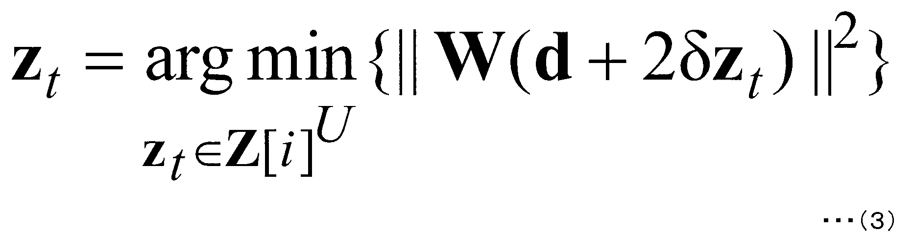
ここで、zt=[zt,1,...,zt,U]Tであり、zt,uが第u端末装置3-u宛ての送信データに加算される摂動項となる。
ところで、式(3)は、基地局装置1に接続している全端末装置3がmodulo演算を可能としている場合を想定している。しかし、実際のシステムにおいては、modulo演算をサポートしている端末とサポートしていない端末とが混在する場合がある。また、摂動項を加算することは、システム全体のチャネル容量を最大化するためには有効であるが、各端末装置3それぞれが達成できるチャネル容量を必ずしも最大化するものではないことがある。例えば、データ変調方式がQPSKであり、受信信号対雑音電力比(Signal-to-Noise power Ratio(SNR))が比較的小さい環境下においては、摂動項を加算しない方が、優れた伝送特性を取り得ることが報告されている。つまり、各端末装置3宛ての送信データの全てに摂動項を加算することなく、一部の送信データには摂動項を加算しないように制御した方が、周波数利用効率の改善の上では有効である場合があることを意味している。
そこで、第2の実施形態に係るプリコーディング部107Bでは、プリコーディング切替部603において、各端末装置3に摂動項を加算すべきか否かを制御している。例えば、データ変調方式としてQPSK変調を用いている端末装置3宛ての送信データには摂動項を加算しないように制御する、等の処理を行なうことになる。極端な例を挙げれば、あるRBでは全端末装置3に線形プリコーディングを施し、別のRBでは全端末装置3に非線形プリコーディングを施しても構わない。送信データに施されたプリコーディングの情報は摂動ベクトル探査部605とDMRS位相制御部609に入力される。以下では、送信データに対して摂動項が加算されなかった端末装置3については、線形プリコーディングが施されたと記載し、摂動項が加算された端末装置3については、非線形プリコーディングが施されたと記載していく。
なお、詳細は後述するが、端末装置3において正しく所望信号を復調するためには、自装置宛ての送信信号にどのプリコーディングが施されているかを正しく知る必要がある。そのため、プリコーディングの切替の周期をあまり短くすることは望ましくない。以下の説明では、第1の実施形態と同様に、図10に示す168無線リソースから構成されるRB毎にプリコーディングを切り替えるものとする。
プリコーディング切替部603からの制御情報に基づき、摂動ベクトル探査部605において、適切に摂動ベクトルzt=[zt,1,...,zt,U]Tの探査が行なわれたものとする(つまり、zt,uの一部が0となっている)。探査された摂動ベクトルは送信信号生成部607に入力され、送信信号s=βW(d+2δzt)が生成されることになる。ここでβは送信電力を一定にするための電力正規化項である。電力の正規化はどの無線リソース単位で行なっても構わないが、後述するDMRSに対するプリコーディングのためにも、ある一定数の無線リソースの平均送信電力を一定とするような電力正規化を行なうことが望ましい。以下では、プリコーディングを切り替える単位であるRB毎に電力正規化も行なうものとする。
続いて、DMRSがプリコーディング部107Bに入力された場合の信号処理について説明する。第1の実施形態と同様に、DMRSにはデータ信号と同様のプリコーディングが施される事になる。しかし、本実施形態で対象としているようなリソースアロケーションを行なっている場合、DMRSの空間多重は行なわれないことになるから、プリコーディングは基本的に線形フィルタWの乗算のみを行ない、摂動項の加算は行なわない。また電力正規化については、データ信号と一緒に行なうことになる。なお、DMRSについても空間多重を行なうようにしても構わないが、この場合、DMRSに加算される摂動項を各端末装置3が推定可能なようにするか、もしくは摂動項の加算を行なわないように制御する必要がある。
ただし、プリコーディング切替部603から送信データに施されたプリコーディングの情報を入力されたDMRS位相制御部609では、データ信号への摂動項の加算の有無に応じて、第2のDMRSの信号系列に対して、位相回転を与えるように制御する。具体的には、データ信号に線形プリコーディングが施された端末装置3宛てに送信されるDMRSについては、位相回転は与えられない。一方で、データ信号に非線形プリコーディングが施された端末装置3宛てに送信されるDMRSについては、ある一定の位相回転を与えるように制御される。与える位相回転量については、第1の実施形態と同様にπとしても良いが、任意の値を与えても構わない。ただし、位相回転量は基地局装置1と各端末装置3の間で共有しておく必要がある。なお、共有が為されているのであれば、各端末装置3で位相回転量を変化させても構わない。また、RB毎に与える位相回転量を変化させるように制御しても構わない。
プリコーディングおよび電力正規化が施されたDMRSはデータ信号と同様に、アンテナ部109に向けて出力される事になる。なお、CRSについては、何らプリコーディングを施されることなく送信される事になる。ただし、電力正規化については、データ信号やDMRSと同様に行なっても良い。
[2.3.端末装置3]
第2の実施形態に係る端末装置3の装置構成は図6と同じであり、各装置における信号処理も第1の実施形態とほぼ同じであるため、説明は省略する。ただし、伝搬路推定部411については、新たにCRSが入力される事になる。伝搬路推定部411は受信されたCRSに基づき、伝搬路情報(式(2)参照)を推定し、その推定結果をフィードバック情報生成部413に入力する。フィードバック情報生成部413では、入力された伝搬路推定値を基地局装置1に通知可能な信号に変換する。最終的には、無線送信部414より基地局装置1に向けて送信される事になる。
第2の実施形態に係る端末装置3の装置構成は図6と同じであり、各装置における信号処理も第1の実施形態とほぼ同じであるため、説明は省略する。ただし、伝搬路推定部411については、新たにCRSが入力される事になる。伝搬路推定部411は受信されたCRSに基づき、伝搬路情報(式(2)参照)を推定し、その推定結果をフィードバック情報生成部413に入力する。フィードバック情報生成部413では、入力された伝搬路推定値を基地局装置1に通知可能な信号に変換する。最終的には、無線送信部414より基地局装置1に向けて送信される事になる。
フィードバック情報の生成方法としては、何かに限定されるものではないが、例えば、伝搬路推定値を直接有限ビット数で量子化し、ディジタル変調した後送信しても良いし、基地局装置1と端末装置3の間で共用するコードブックを用いて通知しても構わない。
なお、同じRBにおいて空間多重されている全端末装置3が同じプリコーディング方式が施される場合、これまで説明してきたようにDMRSに位相回転を与えるのではなく、CRS等のサウンディング信号に位相回転を与えることで、プリコーディング方式を通知することも可能である。この場合、一部のCRSにのみ位相回転を施し、位相回転を施していないCRSと、位相回転を施したCRSとから推定された伝搬路情報の誤差をそれぞれ比較することでプリコーディング方式を推定することが可能となる。
以上説明してきたように、第2の実施形態では、基地局装置1に接続している複数の端末装置3と同時に通信を行なうMU-MIMO伝送を対象に、複数のプリコーディング方式が選択的、もしくは同時に行なわれる伝送において、DMRSの位相回転量を変化させることで、適用されているプリコーディング方式を各端末装置3に正確に通知する方法を対象とした。なお、以上の説明では、複数のプリコーディングの一例として、線形プリコーディングと非線形プリコーディングの2つを例に取り上げて説明してきたが、本発明が対象とするプリコーディングはこの組み合わせに限ったものではない。
例えば、線形プリコーディングに限った場合でも、線形フィルタの算出規範として、ZF規範や、送信信号と受信信号との平均二乗誤差を最小とするMMSE規範、送信信号電力と、他の端末送信電力に与える干渉電力との比を最大とするSLR規範など様々にある。また、本実施形態では、端末装置3の伝搬路補償部415で行なわれるチャネル等化処理が単純な同期検波で済むようなプリコーディングを施したが、端末装置3の伝搬路補償部415において、空間検出処理が必要となるようなプリコーディング(例えば、ブロック対角化法等)も存在する。
本実施形態で対象とするのは、このように様々なプリコーディングが選択的もしくは同時に用いられた場合に、DMRSに与えた位相回転により、端末装置3が今施されているプリコーディングがいずれであるかを把握するような無線通信システムである。なお、基地局装置1が可能なプリコーディングの方法が3つ以上である場合、DMRSに与える位相回転量と、プリコーディング方式とを関連付けておけば良い。例えば、プリコーディングとしてA、B、Cの3つが適用可能である場合、プリコーディングAの場合は位相回転を与えず、Bの場合は、π/2の位相回転を与え、Cの場合は、3π/2の位相回転を与えるようにすれば良い。
端末装置3の伝搬路推定部411においては、第2のDMRSに対して、可能性のある全ての位相回転量を考慮した伝搬路推定値を算出し、第1のDMRSによって推定された伝搬路推定値との誤差を図ることで、どのプリコーディングが施されたかを把握することが可能となる。
第2の実施形態では、MU-MIMO伝送を対象に、複数のプリコーディングが選択的、もしくは同時に施される場合を対象とした。本実施形態によれば、後方互換性を保ちつつ新たなプリコーディング方式を追加していくことが可能となるから、無線通信システムの高度化に寄与することができ、ひいては周波数利用効率の改善に寄与できる。
[3.第3の実施形態]
第1および第2の実施形態では、DMRSに対して与えた位相回転量により、受信された信号に施されているプリコーディングがいずれであるかを、端末装置3が把握する場合を対象としてきた。このことは、本来伝搬路状態情報を推定することが目的であるDMRSを使って、伝搬路情報以外の情報を基地局装置1より端末装置3に送信していると捉えることができる。第3の実施形態では、DMRSの位相情報を用いて、任意の情報を通知する場合を対象とする。
第1および第2の実施形態では、DMRSに対して与えた位相回転量により、受信された信号に施されているプリコーディングがいずれであるかを、端末装置3が把握する場合を対象としてきた。このことは、本来伝搬路状態情報を推定することが目的であるDMRSを使って、伝搬路情報以外の情報を基地局装置1より端末装置3に送信していると捉えることができる。第3の実施形態では、DMRSの位相情報を用いて、任意の情報を通知する場合を対象とする。
[3.1.基地局装置1]
基地局装置1の構成は、第1および第2の実施形態と同様であり、異なるのは、プリコーディング部107がプリコーディング部107Cとなる点のみであるから、以下では、第3の実施形態に係るプリコーディング部107Cにおける信号処理について説明する。
基地局装置1の構成は、第1および第2の実施形態と同様であり、異なるのは、プリコーディング部107がプリコーディング部107Cとなる点のみであるから、以下では、第3の実施形態に係るプリコーディング部107Cにおける信号処理について説明する。
[3.2.プリコーディング部107C]
図12は、本発明の第3の実施形態に係るプリコーディング部107Cの装置構成を示すブロック図である。図12に示す通り、プリコーディング部107Cは、線形フィルタ生成部601と、プリコーディング切替部603と、摂動ベクトル探査部605と、送信信号生成部607と、DMRS位相制御部701とを含んで構成されている。各装置の信号処理は、DMRS位相制御部701を除き、図11と同様であり、データ信号が入力された場合の信号処理は、第2の実施形態とほぼ同様となるから説明は省略する(データ信号が入力されたとき、DMRS位相制御部701は何ら信号処理を行なわない)。ただし、第3の実施形態においては、必ずしも複数のプリコーディング方法を選択的、もしくは同時に用いる必要は無いから、プリコーディング切替部603は無くても構わない。また、摂動ベクトル探査部605が摂動項の探査を一切行なわない、すなわち、線形プリコーディングを施すように制御しても構わない。
図12は、本発明の第3の実施形態に係るプリコーディング部107Cの装置構成を示すブロック図である。図12に示す通り、プリコーディング部107Cは、線形フィルタ生成部601と、プリコーディング切替部603と、摂動ベクトル探査部605と、送信信号生成部607と、DMRS位相制御部701とを含んで構成されている。各装置の信号処理は、DMRS位相制御部701を除き、図11と同様であり、データ信号が入力された場合の信号処理は、第2の実施形態とほぼ同様となるから説明は省略する(データ信号が入力されたとき、DMRS位相制御部701は何ら信号処理を行なわない)。ただし、第3の実施形態においては、必ずしも複数のプリコーディング方法を選択的、もしくは同時に用いる必要は無いから、プリコーディング切替部603は無くても構わない。また、摂動ベクトル探査部605が摂動項の探査を一切行なわない、すなわち、線形プリコーディングを施すように制御しても構わない。
続いて、DMRSが入力された場合の信号処理について説明する。詳細な説明の前に、ここで、第u端末装置3-uが受信するデータ信号および第1のDMRS(つまり、特別な位相回転が与えられていないDMRS)について考える。両者はそれぞれ式(4)で与えられる。
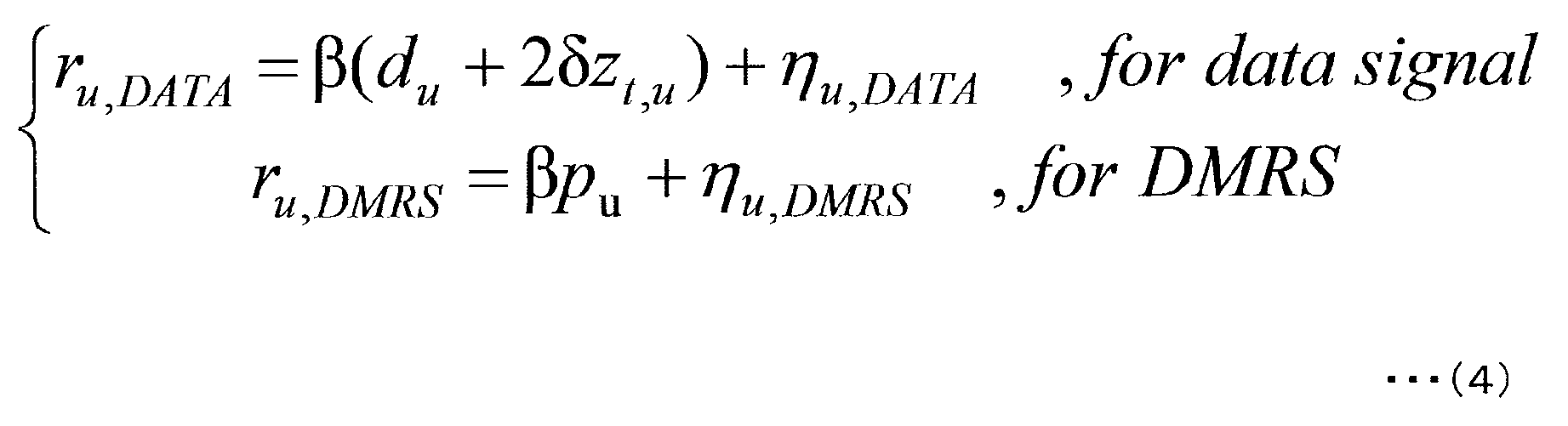
ここで、ηはそれぞれの受信信号に印加される白色性ガウス雑音である。なお、データ信号には非線形プリコーディングが施されている一方で、DMRSについては、空間多重は行なわずに送信したものとしている。通常、端末装置3は、ru,DMRSから既知信号であるpuを除算することで、電力正規化項βを推定し、その推定結果を用いて、ru,DATAからβを除算し、その後でmodulo演算を施すことで所望信号duを復調する。
このとき、βは実数であるから、受信SNRが十分に高く、また|pu|=1であれば、abs(ru,DMRS)の計算結果がru,DMRSから推定した情報そのものであることが分かる。つまり、DMRSには基地局装置1と端末装置3の間で共有せずに任意の位相回転を与えて良いことを意味している。ただし、実際のシステムにおいては、ru,DATAから推定すべき情報は電力正規化項βだけではなく、伝搬路情報のフィードバックから、データ信号が受信されるまでに変動してしまった伝搬路情報成分や、基地局装置1と端末装置3の発振器の周波数が異なることから発生する位相回転に関する情報も含まれている。以下では、このことを踏まえつつ、DMRSに与えた位相回転情報より任意の情報を基地局装置1より端末装置3に通知する方法を示す。
リソースアロケーションとしては、第2の実施形態で例として取り上げた図10で示されたものを用いるものとする。ただし、理由は後述するが、実際は、第1のDMRSと第2のDMRSとは、同じOFDM信号内に存在することが望ましい。
まず第1のDMRSがプリコーディング部107Cに入力された場合については、第1および第2の実施形態と同様に、特別な位相回転等を与えることなくデータ信号と同様のプリコーディングを施す。そして第2のDMRSがプリコーディング部107Cに入力されたとき、DMRS位相制御部701は、基地局装置1が各端末装置3に送りたい情報に基づき、DMRSに対して位相回転を与える。
位相回転の与え方として、本発明においては、何かに限定されるものではないが、例えば、QPSK変調と同様の変調を施せば良い。つまり、本実施形態において例として挙げているリソースアロケーションによれば、第2のDMRSは、各端末装置3に対して1RB当たり6無線リソース確保されているから、もしそれぞれに対して、QPSK変調が施された信号を送信してやれば、6ビットの情報を通知することが可能となる。電力正規化等の他の信号処理については、第1のDMRSと同様であるから説明は省略する。
[3.3.端末装置3]
図13は、本発明の第3の実施形態に係る端末装置3の構成を示すブロック図である。図13に示すように、端末装置3は、アンテナ401と、無線受信部403と、GI除去部405と、FFT部407と、参照信号分離部409と、伝搬路推定部801と、フィードバック情報生成部413と、無線送信部414と、伝搬路補償部415と、デマッピング部417とデータ復調部419と、チャネル復号部421と、情報復調部803とを含んで構成されている。端末装置3の構成は図6とほぼ同じであり、各装置で行なわれる信号処理もほぼ同じであるが、情報復調部803と伝搬路推定部801における信号処理および、その出力が異なるから、以下では、伝搬路推定部801と情報復調部803における信号処理についてのみ説明をする。
図13は、本発明の第3の実施形態に係る端末装置3の構成を示すブロック図である。図13に示すように、端末装置3は、アンテナ401と、無線受信部403と、GI除去部405と、FFT部407と、参照信号分離部409と、伝搬路推定部801と、フィードバック情報生成部413と、無線送信部414と、伝搬路補償部415と、デマッピング部417とデータ復調部419と、チャネル復号部421と、情報復調部803とを含んで構成されている。端末装置3の構成は図6とほぼ同じであり、各装置で行なわれる信号処理もほぼ同じであるが、情報復調部803と伝搬路推定部801における信号処理および、その出力が異なるから、以下では、伝搬路推定部801と情報復調部803における信号処理についてのみ説明をする。
図14は、本発明の第3の実施形態に係る端末装置3の伝搬路推定部801において、DMRSが入力された場合の信号処理を説明するフローチャートである。以下では、図14に基づき、伝搬路推定部801における信号処理について説明する。なお、CRSが入力された場合の信号処理については、第2の実施形態における伝搬路推定部411と同様であるから、説明は省略する。
まず、第1のDMRSに基づき伝搬路推定値Hを取得する(ステップS201)。ここで、第1のDMRSが受信されたときの、第u端末装置3-uの受信信号は式(5)で与えられるものとする。
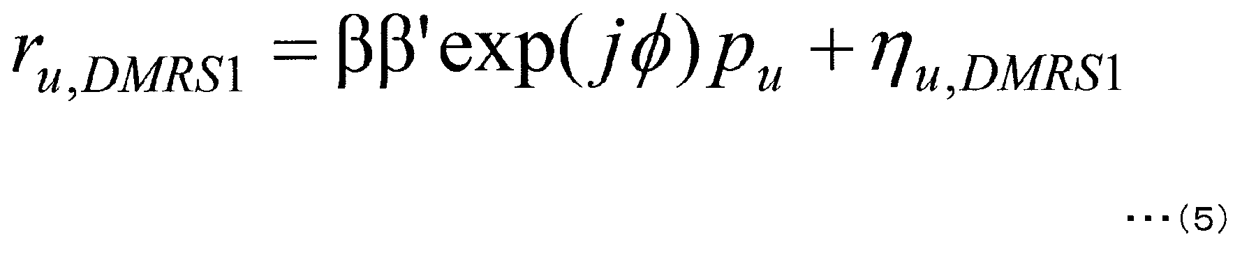
ここで、β’およびφは、伝搬路の時間変動や、発振器の周波数オフセットによって発生した受信信号に対する振幅および位相の変動成分を表している(理想的な環境であれば、β’=1およびφ=0となる)。以下では、雑音成分については記載を省略して説明していく。このとき、伝搬路推定値Hはβ×β’×exp(jφ)で与えられることになる。
続いて、angle(ru,DMRS1)を計算し、位相変動成分exp(jφ)を推定する(ステップS202)。
次いで、第2のDMRSに対する信号処理を行なう。第u端末装置3-uの第2のDMRSの受信信号は式(6)で与えられる。

ここで、αuは基地局装置1が第u端末装置3-uに通知したかった情報に基づいて決定される位相回転量であり、第u端末装置3-uにとっては未知の情報となる。伝搬路推定部801では、第2のDMRSの受信信号ru,DMRS2に、先ほど推定された結果を用いてexp(-jφ)を乗算することで、位相変動成分を取り除かれた受信信号ru,DMRS2’を算出する(ステップS203)。位相変動成分は本来時間変動する値であるから、この信号処理が高精度に行なわれるためには、第1のDMRSと第2のDMRSとは、可能な限り互いの時間相関が高い無線リソースにおいて、送信される事が望ましい。
次いで、angle(ru,DMRS2’)を計算することで、αuを推定する(ステップS204)。
続いて、abs(ru,DMRS2)=β×β’とangle(ru,DMRS2×exp(-jαu))=φを計算することで、第1のDMRSと同様の伝搬路推定値H’=β×β’×exp(jφ)を推定する(ステップS205)。最後に、第1のDMRSと第2のDMRSから推定された伝搬路推定値に対して、平均化等の適切な補間処理を施したのち、伝搬路補償部415に向けて出力する(ステップS206)。なお、ステップS204で推定されたαuは情報復調部803に入力される。
続いて、情報復調部803における信号処理について説明する。情報復調部803では、予め基地局装置1と各端末装置3の間で取り決めていた方法により、αuより情報を抽出する。例えば、第1および第2の実施形態のように、複数のプリコーディングが選択的、もしくは同時に用いられる通信システムにおいては、αuの値と、各端末装置3宛てのデータ信号に用いられているプリコーディング方法を関連付ける方法が考えられる。この場合、情報復調部803の出力は伝搬路補償部415、もしくはチャネル復号部421に向けて出力される事になる(図13では、伝搬路補償部415に向けて出力した場合を示している)また、第2のDMRSについて、QPSK等の位相変調信号を用いるものとすれば、基地局装置1は各端末装置3に対して、任意の情報を送信することが可能であり、この場合、情報復調部803の出力は、そのまま第u端末装置3宛ての情報として出力されることになる。
以上が、第3の実施形態に係る伝搬路推定部801と情報復調部803におけるDMRSに対する信号処理となる。第1のDMRSと第2のDMRSが送信されている無線リソース間の時間相関が十分に大きく、また、受信SNRが十分に大きい環境下であれば、第2のDMRSにより基地局装置1から各端末装置3に向けて新たに任意の情報ビットを通知することが可能となる。
第2のDMRSによって送信される情報ビットにも、チャネル符号化を行なうことは可能であり、元々データ信号として送信している情報ビットと一緒にチャネル符号化を行なっても構わない。ただし、第2のDMRSによって、プリコーディング方法などを通知している場合、チャネル復号が行なわれるまで、伝搬路補償部415における信号処理が行なわれないことを示唆している。よって、制御情報を通知する場合、同一信号を複数回送信する等の、単純かつ復号遅延があまり発生しない方法により誤り制御を行なうことが望ましい。
第3の実施形態では、基地局装置1から各端末装置3に向けて第2のDMRSにより任意の情報ビットを通知する場合を対象とした。第3の実施形態の方法によれば、一部のDMRSによって情報ビットを送信することも可能となることから、プリコーディングを行なうMIMO伝送における更なる周波数利用効率の改善に寄与できる。
[4.全実施形態共通]
以上、この発明の実施形態について図面を参照して詳述してきたが、具体的な構成はこの実施形態に限られるものではなく、この発明の要旨を逸脱しない範囲の設計等も特許請求の範囲に含まれる。
以上、この発明の実施形態について図面を参照して詳述してきたが、具体的な構成はこの実施形態に限られるものではなく、この発明の要旨を逸脱しない範囲の設計等も特許請求の範囲に含まれる。
本発明に関わる移動局装置および基地局装置1で動作するプログラムは、本発明に関わる上記実施形態の機能を実現するように、CPU等を制御するプログラム(コンピュータを機能させるプログラム)である。そして、これら装置で取り扱われる情報は、その処理時に一時的にRAMに蓄積され、その後、各種ROMやHDDに格納され、必要に応じてCPUによって読み出し、修正・書き込みが行なわれる。プログラムを格納する記録媒体としては、半導体媒体(例えば、ROM、不揮発性メモリカード等)、光記録媒体(例えば、DVD、MO、MD、CD、BD等)、磁気記録媒体(例えば、磁気テープ、フレキシブルディスク等)等のいずれであってもよい。また、ロードしたプログラムを実行することにより、上述した実施形態の機能が実現されるだけでなく、そのプログラムの指示に基づき、オペレーティングシステムあるいは他のアプリケーションプログラム等と共同して処理することにより、本発明の機能が実現される場合もある。
また市場に流通させる場合には、可搬型の記録媒体にプログラムを格納して流通させたり、インターネット等のネットワークを介して接続されたサーバコンピュータに転送したりすることができる。この場合、サーバコンピュータの記憶装置も本発明に含まれる。また、上述した実施形態における移動局装置および基地局装置1の一部、または全部を典型的には集積回路であるLSIとして実現してもよい。移動局装置および基地局装置1の各機能ブロックは個別にプロセッサ化してもよいし、一部、または全部を集積してプロセッサ化してもよい。また、集積回路化の手法はLSIに限らず専用回路、または汎用プロセッサで実現しても良い。また、半導体技術の進歩によりLSIに代替する集積回路化の技術が出現した場合、当該技術による集積回路を用いることも可能である。
1 基地局装置
3、3-1、3-2、3-3、3-4 端末装置
5 干渉源
101 チャネル符号化部
103 データ変調部
105 マッピング部
107、107A、107B、107C プリコーディング部
109 アンテナ部
111 制御情報取得部
113 干渉情報取得部
201 IFFT部
203 GI挿入部
205 無線送信部
207 無線受信部
209 アンテナ
301 干渉抑圧部
303 Modulo演算部
305 プリコーディング切替部
307A、307B スイッチ
309 DMRS位相制御部
401 アンテナ
403 無線受信部
405 GI除去部
407 FFT部
409 参照信号分離部
411 伝搬路推定部
413 フィードバック情報生成部
414 無線送信部
415 伝搬路補償部
417 デマッピング部
419 データ復調部
421 チャネル復号部
501 伝搬路情報取得部
601 線形フィルタ生成部
603 プリコーディング切替部
605 摂動ベクトル探査部
607 送信信号生成部
609 DMRS位相制御部
701 DMRS位相制御部
801 伝搬路推定部
803 情報復調部
3、3-1、3-2、3-3、3-4 端末装置
5 干渉源
101 チャネル符号化部
103 データ変調部
105 マッピング部
107、107A、107B、107C プリコーディング部
109 アンテナ部
111 制御情報取得部
113 干渉情報取得部
201 IFFT部
203 GI挿入部
205 無線送信部
207 無線受信部
209 アンテナ
301 干渉抑圧部
303 Modulo演算部
305 プリコーディング切替部
307A、307B スイッチ
309 DMRS位相制御部
401 アンテナ
403 無線受信部
405 GI除去部
407 FFT部
409 参照信号分離部
411 伝搬路推定部
413 フィードバック情報生成部
414 無線送信部
415 伝搬路補償部
417 デマッピング部
419 データ復調部
421 チャネル復号部
501 伝搬路情報取得部
601 線形フィルタ生成部
603 プリコーディング切替部
605 摂動ベクトル探査部
607 送信信号生成部
609 DMRS位相制御部
701 DMRS位相制御部
801 伝搬路推定部
803 情報復調部
Claims (12)
- 無線受信装置と無線通信を行なう無線送信装置に適用されるプリコーディング装置であって、
前記無線受信装置から取得した制御情報に基づいて、データ信号および複数種類の固有参照信号にプリコーディングを施し、
前記各種類の固有参照信号に位相回転を与え、
前記位相回転の位相回転量を、前記無線受信装置に対して通知する情報に関連付けることを特徴とするプリコーディング装置。 - 前記データ信号および複数種類の固有参照信号に対し、複数種類のプリコーディング方式のうちいずれかのプリコーディング方式を選択的にまたは同時に用いてプリコーディングを施し、
前記位相回転の位相回転量が、前記用いられたプリコーディング方式を示すことを特徴とする請求項1記載のプリコーディング装置。 - 前記データ信号に対し、線形プリコーディングを施す場合は、第1の固有参照信号および第2の固有参照信号に同一の位相回転量の位相回転を与える一方、
前記データ信号に対し、非線形プリコーディングを施す場合は、第1の固有参照信号および第2の固有参照信号にそれぞれ異なる位相回転量の位相回転を与えることを特徴とする請求項2記載のプリコーディング装置。 - 請求項1から請求項3のいずれかに記載のプリコーディング装置と、複数の送信アンテナとを備え、複数の無線受信装置のそれぞれに対して、データ信号および固有参照信号を送信する無線送信装置であって、
複数の前記無線受信装置宛てに送信するデータ信号の一部および前記固有参照信号に対して、複数の前記無線受信装置から通知される制御情報に基づいて、前記無線受信装置で観測される干渉を抑制するプリコーディングを施し、複数の前記無線受信装置宛てに送信するデータ信号の一部を、同一の無線リソースで空間多重して送信することを特徴とする無線送信装置。 - 無線送信装置と無線通信を行なう無線受信装置であって、
前記無線送信装置に対して、制御情報を通知し、
前記無線送信装置から、前記通知した制御情報に基づいてプリコーディングされた自装置宛てのデータ信号および複数種類の固有参照信号を受信し、前記各種類の固有参照信号に与えられた位相回転の位相回転量を抽出し、前記抽出した位相回転量に関連付けられた情報を獲得することを特徴とする無線受信装置。 - 前記データ信号および複数種類の固有参照信号は、複数種類のプリコーディング方式のうちいずれかのプリコーディング方式を選択的にまたは同時に用いたプリコーディングが施されており、
前記位相回転量に基づいて、前記用いられたプリコーディング方式を認識し、前記受信したデータ信号を復調することを特徴とする請求項5記載の無線受信装置。 - 第1の固有参照信号および第2の固有参照信号に同一の位相回転量の位相回転が与えられている場合は、前記データ信号に対し、線形プリコーディングが施されていると判断する一方、
第1の固有参照信号および第2の固有参照信号にそれぞれ異なる位相回転量の位相回転が施されている場合は、前記データ信号に対し、非線形プリコーディングが施されていると判断し、前記受信したデータ信号を復調することを特徴とする請求項6記載の無線受信装置。 - 前記位相回転量に基づいたプリコーディング方式の判断に関わらず、前記受信したデータ信号に対し、非線形プリコーディングが施されているとして、前記データ信号を復調することを特徴とする請求項7記載の無線受信装置。
- 前記受信したデータ信号に対し、非線形プリコーディングが施されているとした場合は、modulo演算を含む非線形処理を行なうことを特徴とする請求項8記載の無線受信装置。
- 請求項4記載の無線送信装置と、請求項5から請求項9のいずれかに記載の無線受信装置と、から構成されることを特徴とする無線通信システム。
- 無線受信装置と無線通信を行なう無線送信装置に実装され、前記無線送信装置に複数の機能を発揮させる集積回路であって、
前記無線受信装置から制御情報を取得する機能と、
前記制御情報に基づいて、データ信号および複数種類の固有参照信号に対し、線形プリコーディング方式または非線形プリコーディング方式のうちいずれかのプリコーディング方式を選択的にまたは同時に用いてプリコーディングを施す機能と、
前記データ信号に対し、線形プリコーディングを施す場合は、第1の固有参照信号および第2の固有参照信号に同一の位相回転量の位相回転を与える一方、前記データ信号に対し、非線形プリコーディングを施す場合は、第1の固有参照信号および第2の固有参照信号にそれぞれ異なる位相回転量の位相回転を与える機能と、を少なくとも有し、
前記位相回転の位相回転量が、前記用いられたプリコーディング方式を示すことを特徴とする集積回路。 - 無線送信装置と無線通信を行なう無線受信装置に実装され、前記無線受信装置に複数の機能を発揮させる集積回路であって、
前記無線送信装置に対して、制御情報を通知する機能と、
前記無線送信装置から、前記通知した制御情報に基づいて線形プリコーディングまたは非線形プリコーディングされた自装置宛てのデータ信号並びに第1の固有参照信号および第2の固有参照信号を受信する機能と、
前記第1の固有参照信号および前記第2の固有参照信号に同一の位相回転量の位相回転が与えられている場合は、前記データ信号に対し、線形プリコーディングが施されていると判断する一方、前記第1の固有参照信号および前記第2の固有参照信号にそれぞれ異なる位相回転量の位相回転が施されている場合は、前記データ信号に対し、非線形プリコーディングが施されていると判断する機能と、
前記判断の結果に基づいて、前記受信したデータ信号を復調する機能と、を少なくとも有することを特徴とする集積回路。
Priority Applications (1)
| Application Number | Priority Date | Filing Date | Title |
|---|---|---|---|
| US14/382,855 US20150023279A1 (en) | 2012-03-06 | 2013-03-04 | Pre-coding device, wireless transmission device, wireless receiving device, wireless communication system, and integrated circuit |
Applications Claiming Priority (2)
| Application Number | Priority Date | Filing Date | Title |
|---|---|---|---|
| JP2012049149A JP5908307B2 (ja) | 2012-03-06 | 2012-03-06 | プリコーディング装置、無線送信装置、無線受信装置、無線通信システムおよび集積回路 |
| JP2012-049149 | 2012-03-06 |
Publications (1)
| Publication Number | Publication Date |
|---|---|
| WO2013133192A1 true WO2013133192A1 (ja) | 2013-09-12 |
Family
ID=49116670
Family Applications (1)
| Application Number | Title | Priority Date | Filing Date |
|---|---|---|---|
| PCT/JP2013/055784 Ceased WO2013133192A1 (ja) | 2012-03-06 | 2013-03-04 | プリコーディング装置、無線送信装置、無線受信装置、無線通信システムおよび集積回路 |
Country Status (3)
| Country | Link |
|---|---|
| US (1) | US20150023279A1 (ja) |
| JP (1) | JP5908307B2 (ja) |
| WO (1) | WO2013133192A1 (ja) |
Families Citing this family (14)
| Publication number | Priority date | Publication date | Assignee | Title |
|---|---|---|---|---|
| JP2016157992A (ja) * | 2013-07-04 | 2016-09-01 | シャープ株式会社 | 端末装置、基地局装置および送信方法 |
| JP2017022427A (ja) * | 2013-11-07 | 2017-01-26 | シャープ株式会社 | 通信システム、基地局装置、および端末装置 |
| WO2018048055A2 (ko) * | 2016-09-08 | 2018-03-15 | 엘지전자 주식회사 | 무선 통신 시스템에서 전송 포트의 위상 회전을 추정하기 위한 방법 및 이를 위한 장치 |
| US10411914B2 (en) | 2016-12-14 | 2019-09-10 | Intel IP Corporation | Data detection in MIMO systems with demodulation and tracking reference signals |
| WO2018142506A1 (ja) * | 2017-02-01 | 2018-08-09 | 三菱電機株式会社 | 送信装置、受信装置、基地局、端末および送信方法 |
| US11184205B2 (en) * | 2018-05-10 | 2021-11-23 | Ntt Docomo, Inc. | Reception apparatus and transmission apparatus |
| CN108880637B (zh) * | 2018-07-27 | 2020-11-13 | 电子科技大学 | 基于码本的多符号联合旋转thp预编码方法 |
| WO2020019336A1 (en) * | 2018-07-27 | 2020-01-30 | Nokia Shanghai Bell Co., Ltd. | Method and apparatus for transmiting demodulation reference signal |
| WO2021186678A1 (ja) * | 2020-03-19 | 2021-09-23 | 日本電信電話株式会社 | 無線通信方法及び無線通信システム |
| CN114499600B (zh) * | 2020-11-12 | 2023-04-18 | 华为技术有限公司 | 多用户预编码方法、装置及设备 |
| US12388494B2 (en) * | 2021-01-26 | 2025-08-12 | Nippon Telegraph And Telephone Corporation | Communication path estimation method, wireless communication system, transmitter, and receiver |
| US11463134B2 (en) * | 2021-02-11 | 2022-10-04 | Nxp Usa, Inc. | Secure Wi-Fi communication by perturbation of a spatial mapping matrix |
| WO2023043347A1 (en) * | 2021-09-17 | 2023-03-23 | Telefonaktiebolaget Lm Ericsson (Publ) | Determining precoding parameters |
| WO2023238687A1 (ja) * | 2022-06-07 | 2023-12-14 | ソニーグループ株式会社 | アンテナ装置及び無線装置 |
Citations (5)
| Publication number | Priority date | Publication date | Assignee | Title |
|---|---|---|---|---|
| WO2007049760A1 (ja) * | 2005-10-28 | 2007-05-03 | Matsushita Electric Industrial Co., Ltd. | 送信装置、受信装置、送信方法、受信方法及び無線通信システム |
| WO2010109518A1 (ja) * | 2009-03-24 | 2010-09-30 | 富士通株式会社 | 無線通信システム、端末装置、基地局装置、及び無線通信システムにおける無線通信方法 |
| JP2011146995A (ja) * | 2010-01-15 | 2011-07-28 | Sharp Corp | 通信システム、通信装置、通信方法およびそのプロセッサ |
| JP2013031132A (ja) * | 2011-07-29 | 2013-02-07 | Sharp Corp | 無線受信装置およびプログラム |
| JP2013042350A (ja) * | 2011-08-15 | 2013-02-28 | Sharp Corp | 無線送信装置、無線受信装置、プログラム、集積回路および無線通信システム |
Family Cites Families (25)
| Publication number | Priority date | Publication date | Assignee | Title |
|---|---|---|---|---|
| JPH09181701A (ja) * | 1995-12-26 | 1997-07-11 | Sharp Corp | スペクトル拡散通信方式 |
| US8320301B2 (en) * | 2002-10-25 | 2012-11-27 | Qualcomm Incorporated | MIMO WLAN system |
| DE10333514B4 (de) * | 2003-07-17 | 2005-10-13 | Siemens Ag | Nichtlineares Vorcodierungsverfahren für einen digitalen Broadcastkanal |
| JP4765322B2 (ja) * | 2005-01-21 | 2011-09-07 | ソニー株式会社 | 無線通信システム、無線通信装置及び無線通信方法、並びにコンピュータ・プログラム |
| TW200935854A (en) * | 2007-10-31 | 2009-08-16 | Qualcomm Inc | Synchronization in a broadcast OFDM system using time division multiplexed pilots |
| KR100932272B1 (ko) * | 2007-12-13 | 2009-12-16 | 한국전자통신연구원 | 멀티 유저 미모를 위한 송신 간섭 제거 방법 |
| JP5047834B2 (ja) * | 2008-02-15 | 2012-10-10 | 株式会社エヌ・ティ・ティ・ドコモ | 無線通信装置及び無線通信方法 |
| US20100041350A1 (en) * | 2008-08-13 | 2010-02-18 | Samsung Electronics, Co., Ltd. | Uplink transmissions with two antenna ports |
| RU2405252C2 (ru) * | 2009-01-21 | 2010-11-27 | Корпорация "САМСУНГ ЭЛЕКТРОНИКС Ко., Лтд." | Способ передачи-приема сигнала в многопользовательской системе радиосвязи с множеством передающих и множеством приемных антенн |
| GB2467143B (en) * | 2009-01-22 | 2011-04-06 | Toshiba Res Europ Ltd | Wireless commication method and apparatus |
| US8838051B1 (en) * | 2009-02-19 | 2014-09-16 | Qualcomm Incorporated | Transmitter beamforming power control |
| CN101854186B (zh) * | 2009-03-30 | 2015-04-01 | 三星电子株式会社 | 用于数据传输的预编/解码方法和系统 |
| EP2242187B1 (en) * | 2009-04-14 | 2015-10-28 | Fraunhofer-Gesellschaft zur Förderung der angewandten Forschung e.V. | Method and device for data processing in a communication network |
| EP2464030B1 (en) * | 2009-08-06 | 2019-01-09 | LG Electronics Inc. | Method and apparatus for transmitting uplink signals in wireless communication system for supporting multiple antenna transmission |
| CN102598523B (zh) * | 2009-09-04 | 2014-12-17 | 株式会社日立制作所 | 在多用户多输入多输出无线传输系统中利用额外的接收机处理的Tomlinson Harashima 预编码 |
| US8483265B2 (en) * | 2009-09-04 | 2013-07-09 | Hitachi, Ltd. | Generalized decision feedback equalizer precoder with input covariance matrix calculation for multi-user multiple-input multiple-output wireless transmission systems |
| JP4896196B2 (ja) * | 2009-10-01 | 2012-03-14 | 株式会社エヌ・ティ・ティ・ドコモ | 協調送信方法、協調送信システム、集約局及び無線基地局 |
| US9887754B2 (en) * | 2010-05-04 | 2018-02-06 | Qualcomm Incorporated | Method and apparatus for optimizing power distribution between symbols |
| WO2011161946A1 (ja) * | 2010-06-21 | 2011-12-29 | パナソニック株式会社 | 端末装置、基地局装置、再送方法及びリソース割り当て方法 |
| WO2012017818A1 (ja) * | 2010-08-02 | 2012-02-09 | シャープ株式会社 | 通信装置および通信システム |
| US8488529B2 (en) * | 2011-01-05 | 2013-07-16 | Telefonaktiebolaget Lm Ericsson (Publ) | Efficient information mapping for transmission grants |
| US20120182944A1 (en) * | 2011-01-19 | 2012-07-19 | Telefonaktiebolaget Lm Ericsson (Publ) | Methods and arrangements for signaling channel state information |
| CN103733694B (zh) * | 2011-08-09 | 2018-01-23 | 瑞典爱立信有限公司 | 用于上行链路功率控制的方法和布置 |
| JP5859786B2 (ja) * | 2011-09-16 | 2016-02-16 | シャープ株式会社 | 無線送信装置、無線受信装置、無線通信システム、プログラムおよび集積回路 |
| WO2013119152A1 (en) * | 2012-02-08 | 2013-08-15 | Telefonaktiebolaget L M Ericsson (Publ) | Method and arrangement for supporting adjustment of transmission from correlated antennas |
-
2012
- 2012-03-06 JP JP2012049149A patent/JP5908307B2/ja active Active
-
2013
- 2013-03-04 WO PCT/JP2013/055784 patent/WO2013133192A1/ja not_active Ceased
- 2013-03-04 US US14/382,855 patent/US20150023279A1/en not_active Abandoned
Patent Citations (5)
| Publication number | Priority date | Publication date | Assignee | Title |
|---|---|---|---|---|
| WO2007049760A1 (ja) * | 2005-10-28 | 2007-05-03 | Matsushita Electric Industrial Co., Ltd. | 送信装置、受信装置、送信方法、受信方法及び無線通信システム |
| WO2010109518A1 (ja) * | 2009-03-24 | 2010-09-30 | 富士通株式会社 | 無線通信システム、端末装置、基地局装置、及び無線通信システムにおける無線通信方法 |
| JP2011146995A (ja) * | 2010-01-15 | 2011-07-28 | Sharp Corp | 通信システム、通信装置、通信方法およびそのプロセッサ |
| JP2013031132A (ja) * | 2011-07-29 | 2013-02-07 | Sharp Corp | 無線受信装置およびプログラム |
| JP2013042350A (ja) * | 2011-08-15 | 2013-02-28 | Sharp Corp | 無線送信装置、無線受信装置、プログラム、集積回路および無線通信システム |
Non-Patent Citations (2)
| Title |
|---|
| HIROSHI NAKANO ET AL.: "Adaptive THP Scheme Control for Downlink MU-MIMO Systems", IEICE TECHNICAL REPORT, RCS2009-293, 24 February 2010 (2010-02-24), pages 203 - 208 * |
| YOUNG-HAN NAM ET AL.: "Evolution of Reference Signals for LTE-Advanced Systems", COMMUNICATIONS MAGAZINE, vol. 50, no. ISS. 2, February 2012 (2012-02-01), pages 132 - 138, XP011417049, DOI: doi:10.1109/MCOM.2012.6146492 * |
Also Published As
| Publication number | Publication date |
|---|---|
| US20150023279A1 (en) | 2015-01-22 |
| JP5908307B2 (ja) | 2016-04-26 |
| JP2013187612A (ja) | 2013-09-19 |
Similar Documents
| Publication | Publication Date | Title |
|---|---|---|
| JP5908307B2 (ja) | プリコーディング装置、無線送信装置、無線受信装置、無線通信システムおよび集積回路 | |
| US9008166B2 (en) | Filter calculating device, transmitting device, receiving device, processor, and filter calculating method | |
| JP6316205B2 (ja) | 基地局装置、端末装置、無線通信システムおよび集積回路 | |
| JP5596498B2 (ja) | 基地局装置、移動局装置及びそれらを用いた無線通信システム | |
| JP5804594B2 (ja) | プリコーディング装置、プリコーディング用プログラムおよび集積回路 | |
| US8731488B2 (en) | Wireless communication apparatus and method | |
| JP2010518778A (ja) | 組合された循環遅延ダイバーシティと無線信号のプリコーディングの方法およびシステム | |
| WO2014199989A1 (ja) | 基地局装置、端末装置、無線通信システム、集積回路 | |
| JPWO2014069262A1 (ja) | 基地局装置、端末装置および無線通信システム | |
| WO2015186531A1 (ja) | 端末装置、フィードバック情報生成方法、及び基地局装置 | |
| JP5859913B2 (ja) | 無線受信装置、無線送信装置、無線通信システム、プログラムおよび集積回路 | |
| JPWO2014057840A1 (ja) | 端末装置、基地局装置、無線通信システム、受信方法および集積回路 | |
| WO2012157393A1 (ja) | 基地局装置、移動局装置、制御プログラムおよび集積回路 | |
| JP5641787B2 (ja) | 端末装置及びそれを用いた無線通信システム | |
| JP5546357B2 (ja) | 送信装置、受信装置、無線通信システム、制御プログラムおよび集積回路 | |
| WO2013018555A1 (ja) | 無線受信装置およびプログラム | |
| JP2016066827A (ja) | 基地局装置、プリコーディング方法、集積回路、無線通信システム | |
| Ruder et al. | Combined user pairing and spectrum allocation for multiuser SC-FDMA transmission | |
| JP5909104B2 (ja) | 無線送信装置、無線受信装置、無線通信システムおよびプリコーディング方法 | |
| JP6047744B2 (ja) | 無線通信システム、無線通信装置および無線通信方法 | |
| JP5753041B2 (ja) | 無線送信装置、無線受信装置、および無線通信システム | |
| JP2013123196A (ja) | プリコーディング装置、無線送信装置、プリコーディング方法、プログラムおよび集積回路 |
Legal Events
| Date | Code | Title | Description |
|---|---|---|---|
| 121 | Ep: the epo has been informed by wipo that ep was designated in this application |
Ref document number: 13757024 Country of ref document: EP Kind code of ref document: A1 |
|
| WWE | Wipo information: entry into national phase |
Ref document number: 14382855 Country of ref document: US |
|
| NENP | Non-entry into the national phase |
Ref country code: DE |
|
| 122 | Ep: pct application non-entry in european phase |
Ref document number: 13757024 Country of ref document: EP Kind code of ref document: A1 |