WO2013133192A1 - Dispositif de précodage, dispositif d'émission sans fil, dispositif de réception sans fil, système de communication sans fil et circuit intégré - Google Patents
Dispositif de précodage, dispositif d'émission sans fil, dispositif de réception sans fil, système de communication sans fil et circuit intégré Download PDFInfo
- Publication number
- WO2013133192A1 WO2013133192A1 PCT/JP2013/055784 JP2013055784W WO2013133192A1 WO 2013133192 A1 WO2013133192 A1 WO 2013133192A1 JP 2013055784 W JP2013055784 W JP 2013055784W WO 2013133192 A1 WO2013133192 A1 WO 2013133192A1
- Authority
- WO
- WIPO (PCT)
- Prior art keywords
- precoding
- phase rotation
- signal
- wireless
- unit
- Prior art date
Links
Images


Classifications
-
- H—ELECTRICITY
- H04—ELECTRIC COMMUNICATION TECHNIQUE
- H04L—TRANSMISSION OF DIGITAL INFORMATION, e.g. TELEGRAPHIC COMMUNICATION
- H04L5/00—Arrangements affording multiple use of the transmission path
- H04L5/003—Arrangements for allocating sub-channels of the transmission path
- H04L5/0048—Allocation of pilot signals, i.e. of signals known to the receiver
- H04L5/0051—Allocation of pilot signals, i.e. of signals known to the receiver of dedicated pilots, i.e. pilots destined for a single user or terminal
-
- H—ELECTRICITY
- H04—ELECTRIC COMMUNICATION TECHNIQUE
- H04B—TRANSMISSION
- H04B7/00—Radio transmission systems, i.e. using radiation field
- H04B7/02—Diversity systems; Multi-antenna system, i.e. transmission or reception using multiple antennas
- H04B7/04—Diversity systems; Multi-antenna system, i.e. transmission or reception using multiple antennas using two or more spaced independent antennas
- H04B7/0413—MIMO systems
- H04B7/0456—Selection of precoding matrices or codebooks, e.g. using matrices antenna weighting
-
- H—ELECTRICITY
- H04—ELECTRIC COMMUNICATION TECHNIQUE
- H04B—TRANSMISSION
- H04B7/00—Radio transmission systems, i.e. using radiation field
- H04B7/02—Diversity systems; Multi-antenna system, i.e. transmission or reception using multiple antennas
- H04B7/04—Diversity systems; Multi-antenna system, i.e. transmission or reception using multiple antennas using two or more spaced independent antennas
- H04B7/0413—MIMO systems
- H04B7/0452—Multi-user MIMO systems
-
- H—ELECTRICITY
- H04—ELECTRIC COMMUNICATION TECHNIQUE
- H04B—TRANSMISSION
- H04B7/00—Radio transmission systems, i.e. using radiation field
- H04B7/02—Diversity systems; Multi-antenna system, i.e. transmission or reception using multiple antennas
- H04B7/04—Diversity systems; Multi-antenna system, i.e. transmission or reception using multiple antennas using two or more spaced independent antennas
- H04B7/06—Diversity systems; Multi-antenna system, i.e. transmission or reception using multiple antennas using two or more spaced independent antennas at the transmitting station
- H04B7/0613—Diversity systems; Multi-antenna system, i.e. transmission or reception using multiple antennas using two or more spaced independent antennas at the transmitting station using simultaneous transmission
- H04B7/0615—Diversity systems; Multi-antenna system, i.e. transmission or reception using multiple antennas using two or more spaced independent antennas at the transmitting station using simultaneous transmission of weighted versions of same signal
- H04B7/0619—Diversity systems; Multi-antenna system, i.e. transmission or reception using multiple antennas using two or more spaced independent antennas at the transmitting station using simultaneous transmission of weighted versions of same signal using feedback from receiving side
-
- H—ELECTRICITY
- H04—ELECTRIC COMMUNICATION TECHNIQUE
- H04B—TRANSMISSION
- H04B7/00—Radio transmission systems, i.e. using radiation field
- H04B7/02—Diversity systems; Multi-antenna system, i.e. transmission or reception using multiple antennas
- H04B7/04—Diversity systems; Multi-antenna system, i.e. transmission or reception using multiple antennas using two or more spaced independent antennas
- H04B7/06—Diversity systems; Multi-antenna system, i.e. transmission or reception using multiple antennas using two or more spaced independent antennas at the transmitting station
- H04B7/0613—Diversity systems; Multi-antenna system, i.e. transmission or reception using multiple antennas using two or more spaced independent antennas at the transmitting station using simultaneous transmission
- H04B7/0682—Diversity systems; Multi-antenna system, i.e. transmission or reception using multiple antennas using two or more spaced independent antennas at the transmitting station using simultaneous transmission using phase diversity (e.g. phase sweeping)
-
- H—ELECTRICITY
- H04—ELECTRIC COMMUNICATION TECHNIQUE
- H04B—TRANSMISSION
- H04B7/00—Radio transmission systems, i.e. using radiation field
- H04B7/02—Diversity systems; Multi-antenna system, i.e. transmission or reception using multiple antennas
- H04B7/04—Diversity systems; Multi-antenna system, i.e. transmission or reception using multiple antennas using two or more spaced independent antennas
- H04B7/06—Diversity systems; Multi-antenna system, i.e. transmission or reception using multiple antennas using two or more spaced independent antennas at the transmitting station
- H04B7/0697—Diversity systems; Multi-antenna system, i.e. transmission or reception using multiple antennas using two or more spaced independent antennas at the transmitting station using spatial multiplexing
-
- H—ELECTRICITY
- H04—ELECTRIC COMMUNICATION TECHNIQUE
- H04B—TRANSMISSION
- H04B7/00—Radio transmission systems, i.e. using radiation field
- H04B7/02—Diversity systems; Multi-antenna system, i.e. transmission or reception using multiple antennas
- H04B7/04—Diversity systems; Multi-antenna system, i.e. transmission or reception using multiple antennas using two or more spaced independent antennas
- H04B7/08—Diversity systems; Multi-antenna system, i.e. transmission or reception using multiple antennas using two or more spaced independent antennas at the receiving station
- H04B7/0837—Diversity systems; Multi-antenna system, i.e. transmission or reception using multiple antennas using two or more spaced independent antennas at the receiving station using pre-detection combining
- H04B7/0842—Weighted combining
-
- H—ELECTRICITY
- H04—ELECTRIC COMMUNICATION TECHNIQUE
- H04J—MULTIPLEX COMMUNICATION
- H04J11/00—Orthogonal multiplex systems, e.g. using WALSH codes
- H04J11/0023—Interference mitigation or co-ordination
- H04J11/0026—Interference mitigation or co-ordination of multi-user interference
- H04J11/003—Interference mitigation or co-ordination of multi-user interference at the transmitter
- H04J11/0033—Interference mitigation or co-ordination of multi-user interference at the transmitter by pre-cancellation of known interference, e.g. using a matched filter, dirty paper coder or Thomlinson-Harashima precoder
-
- H—ELECTRICITY
- H04—ELECTRIC COMMUNICATION TECHNIQUE
- H04L—TRANSMISSION OF DIGITAL INFORMATION, e.g. TELEGRAPHIC COMMUNICATION
- H04L27/00—Modulated-carrier systems
- H04L27/32—Carrier systems characterised by combinations of two or more of the types covered by groups H04L27/02, H04L27/10, H04L27/18 or H04L27/26
- H04L27/34—Amplitude- and phase-modulated carrier systems, e.g. quadrature-amplitude modulated carrier systems
- H04L27/345—Modifications of the signal space to allow the transmission of additional information
- H04L27/3455—Modifications of the signal space to allow the transmission of additional information in order to facilitate carrier recovery at the receiver end, e.g. by transmitting a pilot or by using additional signal points to allow the detection of rotations
Definitions
- the present invention relates to wireless communication technology.
- MIMO Multiple input multiple output
- the amount of improvement in frequency utilization efficiency by the MIMO technology is proportional to the number of transmission / reception antennas.
- the number of receiving antennas that can be arranged in the terminal device is limited.
- Multi-User-MIMO MU-MIMO
- MU-MIMO Multi-User-MIMO
- MU-MIMO transmission signals destined for each terminal apparatus are received by the terminal apparatus as inter-user-interference (IUI), so it is necessary to suppress IUI.
- IUI inter-user-interference
- LTE long term evolution
- LTE long term evolution
- a linear filter calculated based on propagation path information notified from each terminal device is provided to the base station device.
- Linear precoding that suppresses IUI by multiplying in advance is adopted (hereinafter, MU-MIMO based on linear precoding is also referred to as linear MU-MIMO as a whole).
- 802.11ac which is being standardized as a next-generation wireless LAN system, the adoption of linear MU-MIMO is considered promising.
- MU-MIMO technology based on nonlinear precoding in which nonlinear signal processing is performed on the base station apparatus side is attracting attention (hereinafter referred to as nonlinear precoding).
- MU-MIMO based on this is also called non-linear MU-MIMO as a whole).
- the terminal device If the terminal device is capable of modulo operation, it can add a perturbation vector whose element is a complex number (perturbation term) obtained by multiplying an arbitrary Gaussian integer by a constant real number to the transmitted signal. It becomes.
- Non-Patent Document 1 describes Vector perturbation (VP) as a method that can realize optimal transmission characteristics as nonlinear precoding. While VP can achieve excellent transmission characteristics, the amount of computation increases exponentially in proportion to the number of spatially multiplexed terminals.
- THP Tomlinson Harashima precoding
- Nonlinear MU-MIMO is effective in improving the frequency utilization efficiency of MU-MIMO.
- Non-Patent Document 3 discusses hybrid THP that improves transmission characteristics by adaptively changing the application of modulo arithmetic for MU-MIMO transmission using THP. .
- the terminal apparatus selectively receives a signal that requires a modulo operation for demodulating the signal and a signal that does not require a modulo operation.
- a signal based on linear precoding and a signal based on nonlinear precoding are selectively received.
- Non-Patent Document 4 discusses newly notifying control information that explicitly indicates which precoding method is used. According to this method, the terminal apparatus can correctly grasp the applied precoding scheme, but there is a problem that the overhead is increased.
- the present invention has been made in view of such circumstances, and in a wireless communication system in which a plurality of precodings are selectively or simultaneously used, the terminal device performs any precoding without increasing overhead. It is an object of the present invention to provide a precoding device, a wireless transmission device, a wireless reception device, a wireless communication system, and an integrated circuit capable of grasping whether the transmission is performed.
- the precoding device of the present invention is a precoding device applied to a wireless transmission device that performs wireless communication with a wireless reception device, and based on control information acquired from the wireless reception device, a data signal and a plurality of types
- the unique reference signal is precoded, phase rotation is applied to each type of unique reference signal, and the amount of phase rotation of the phase rotation is associated with information to be notified to the radio reception apparatus.
- the precoding device performs precoding on the data signal and multiple types of unique reference signals based on the control information acquired from the wireless reception device, and applies phase rotation to each type of unique reference signal, thereby rotating the phase. Is associated with the information notified to the wireless reception device, so that it is possible for the wireless transmission device to transmit information bits using a part of DMRS. It can contribute to the improvement of frequency utilization efficiency.
- precoding is performed selectively or simultaneously using one of a plurality of types of precoding schemes for the data signal and a plurality of types of unique reference signals. And the phase rotation amount of the phase rotation indicates the precoding scheme used.
- phase rotation amount of the phase rotation indicates the precoding scheme used, precoding that is actually applied to the radio transmission apparatus in transmission that selectively uses linear precoding and non-linear precoding is used. Since the radio receiving apparatus can correctly grasp the method without notifying the method by the control information, a desired signal can be correctly demodulated from the received signal.
- the precoding device of the present invention when linear precoding is performed on the data signal, the first specific reference signal and the second specific reference signal are subjected to phase rotation of the same phase rotation amount.
- the first unique reference signal and the second unique reference signal are given different phase rotation amounts.
- the precoding apparatus performs linear precoding on the data signal
- the data signal is supplied to the first specific reference signal and the second specific reference signal with the same phase rotation amount.
- phase rotations of different phase rotation amounts are given to the first eigenreference signal and the second eigenreference signal, respectively, so that linear precoding and nonlinear precoding are selectively used.
- the wireless receiver can correctly grasp the precoding method actually applied by the wireless transmitter without using control information, so the desired signal can be correctly demodulated from the received signal. It becomes possible to do.
- the wireless transmission device of the present invention includes the precoding device according to any one of (1) to (3) above and a plurality of transmission antennas, and each of the plurality of wireless reception devices.
- Precoding is performed to suppress interference observed in the wireless reception device, and a part of the data signal transmitted to the plurality of wireless reception devices is spatially multiplexed with the same wireless resource. It is characterized by transmitting.
- the wireless transmission device is a wireless reception device based on control information notified from a plurality of wireless reception devices with respect to a part of data signals and unique reference signals transmitted to the plurality of wireless reception devices.
- Precoding that suppresses observed interference is performed, and a part of the data signal transmitted to a plurality of radio reception apparatuses is spatially multiplexed with the same radio resource, so that in the case of MU-MIMO transmission, Since it becomes possible to add a new precoding method while maintaining compatibility, it is possible to contribute to the advancement of the radio communication system, and thus to improve the frequency utilization efficiency.
- the wireless reception device of the present invention is a wireless reception device that performs wireless communication with a wireless transmission device, and notifies the wireless transmission device of control information, and the wireless transmission device notifies the notification.
- Receiving a pre-coded data signal addressed to its own device based on the control information and a plurality of types of unique reference signals, extracting the phase rotation amount of the phase rotation given to each type of unique reference signal, and extracting It is characterized by acquiring information associated with the phase rotation amount.
- the wireless reception device extracts the phase rotation amount of the phase rotation given to each type of unique reference signal, and acquires information associated with the extracted phase rotation amount. Since it is possible to transmit information bits by a part of DMRS, it is possible to contribute to further improvement of frequency utilization efficiency in MIMO transmission in which precoding is performed.
- the data signal and the plurality of types of unique reference signals may be precoded selectively or simultaneously using any one of a plurality of types of precoding schemes.
- the precoding scheme used is recognized based on the phase rotation amount, and the received data signal is demodulated.
- the radio transmission apparatus is actually used. Since the radio receiving apparatus can correctly grasp the precoding method applied to the control signal without using the control information, a desired signal can be correctly demodulated from the received signal.
- the data signal is linear. If it is determined that precoding has been performed, and if the first specific reference signal and the second specific reference signal have been subjected to phase rotation of different phase rotation amounts, a nonlinear precoding is performed on the data signal. It is determined that coding has been performed, and the received data signal is demodulated.
- the wireless receiver when the wireless receiver receives the same phase rotation amount for the first unique reference signal and the second unique reference signal, linear precoding is performed on the data signal.
- the first unique reference signal and the second unique reference signal are subjected to phase rotation of different phase rotation amounts, nonlinear precoding is applied to the data signal. Therefore, in the transmission that selectively uses the linear precoding and the non-linear precoding, the radio reception apparatus correctly grasps the precoding method that is actually applied by the radio transmission apparatus without reporting the control information. Therefore, the desired signal can be correctly demodulated from the received signal.
- the received data signal is subjected to nonlinear precoding regardless of the determination of the precoding scheme based on the phase rotation amount. Is demodulated.
- the wireless reception device demodulates the data signal assuming that non-linear precoding is applied to the received data signal regardless of the determination of the precoding scheme based on the amount of phase rotation. Transmission characteristics can be obtained.
- the wireless reception device of the present invention is characterized in that, when nonlinear precoding is applied to the received data signal, nonlinear processing including modulo calculation is performed.
- the wireless reception device when the wireless reception device performs nonlinear precoding on the received data signal, nonlinear processing including modulo operation is performed, and therefore linear precoding and nonlinear precoding are selectively performed.
- the wireless reception device since the wireless reception device can correctly grasp the precoding method actually applied by the wireless transmission device without using the control information, a desired signal is obtained from the received signal. It becomes possible to demodulate correctly.
- the wireless communication system of the present invention includes the wireless transmission device according to (4) above and the wireless reception device according to any of (5) to (9) above. It is said.
- the wireless communication system includes the wireless transmission device described in (4) above and the wireless reception device described in any of (5) to (9) above, one wireless transmission device is included. Since it is possible to transmit information bits by a part of DMRS, it is possible to contribute to further improvement of frequency utilization efficiency in MIMO transmission in which precoding is performed.
- An integrated circuit according to the present invention is an integrated circuit that is mounted on a wireless transmission device that performs wireless communication with a wireless reception device, and that allows the wireless transmission device to perform a plurality of functions, and is controlled by the wireless reception device. Based on the control information and a function for obtaining information, either a linear precoding scheme or a non-linear precoding scheme is selectively or simultaneously used for a data signal and a plurality of types of unique reference signals.
- the first unique reference signal and the second unique reference signal are given phase rotation of the same phase rotation amount, while the data signal When nonlinear precoding is applied to the signal, the first unique reference signal and the second unique reference signal are different. That has a function of giving a phase rotation of the phase rotation amount, at least, the phase rotation amount of said phase rotation, is characterized by showing a precoding scheme used above.
- the radio transmission apparatus performs linear precoding on the data signal
- the data signal is supplied while the first unique reference signal and the second unique reference signal are given the same phase rotation amount.
- phase rotations of different phase rotation amounts are given to the first eigenreference signal and the second eigenreference signal, respectively, so that linear precoding and nonlinear precoding are selectively used.
- the wireless receiver can correctly grasp the precoding method actually applied by the wireless transmitter without using control information, so the desired signal can be correctly demodulated from the received signal. It becomes possible to do.
- An integrated circuit is an integrated circuit that is mounted on a wireless reception device that performs wireless communication with a wireless transmission device, and that allows the wireless reception device to perform a plurality of functions.
- a function for notifying control information, and a data signal addressed to the own device that has been linearly or non-linearly precoded based on the notified control information, a first unique reference signal, and a second A function of receiving a unique reference signal and linear precoding for the data signal when the first unique reference signal and the second unique reference signal have the same phase rotation amount
- the first specific reference signal and the second specific reference signal are subjected to phase rotations of different phase rotation amounts.
- the data signal has at least a function of determining that nonlinear precoding is applied to the data signal and a function of demodulating the received data signal based on the result of the determination. .
- the wireless receiver when the wireless receiver receives the same phase rotation amount for the first unique reference signal and the second unique reference signal, linear precoding is performed on the data signal.
- the first unique reference signal and the second unique reference signal are subjected to phase rotation of different phase rotation amounts, nonlinear precoding is applied to the data signal. Therefore, in the transmission that selectively uses the linear precoding and the non-linear precoding, the radio reception apparatus correctly grasps the precoding method that is actually applied by the radio transmission apparatus without reporting the control information. Therefore, the desired signal can be correctly demodulated from the received signal.
- a plurality of precoding can be used selectively or simultaneously without increasing overhead. Therefore, since a new precoding scheme can be added to a system in which a specific precoding scheme has already been standardized, it can contribute to the improvement of the frequency utilization efficiency of the system.
- AT is a transposed matrix of matrix A
- a H is an adjoint (Hermitian transposed) matrix of matrix A
- a -1 is an inverse matrix of matrix A
- a + is a pseudo (or general) inverse matrix of matrix A
- diag (A) is a diagonal matrix obtained by extracting only the diagonal components of the matrix A.
- floor (c) is a floor that returns the largest Gaussian integer whose real part and imaginary part do not exceed the values of the real part and imaginary part of the complex number c, respectively.
- E [x] is the ensemble average of the random variable x
- abs (c) is a function that returns the amplitude of the complex number c
- angle (c) is a function that returns the argument of the complex number c
- Norm and x% y represent the remainder when integer x is divided by integer y.
- [A; B] represents a matrix obtained by combining the two matrices A and B in the row direction, and [A, B] represents a matrix coupled in the column direction.
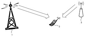
- FIG. 1 is a diagram showing an outline of a radio communication system according to the first embodiment of the present invention.
- one terminal device also referred to as a wireless reception device
- a base station device also referred to as a wireless transmission device
- the terminal device 3 assumes an environment where a signal (desired signal or desired signal) transmitted from the base station device 1 and an interference signal transmitted from the interference source 5 are received.
- the interference signal refers to a signal different from the desired signal, which is transmitted using the same radio resource as the desired signal.
- the same frequency interference (or inter-cell interference) in a cellular system that performs frequency repetition is applicable.
- OFDM orthogonal frequency division multiplexing
- the base station apparatus 1 acquires information on an interference signal received by the terminal apparatus 3 based on the control information notified from the terminal apparatus 3, and performs precoding for each subcarrier on transmission data based on the interference signal information.
- the base station apparatus 1 and the terminal apparatus 3 are each provided with one antenna, and the propagation path between the base station apparatus 1 and the terminal apparatus 3 takes into account only thermal noise applied in the terminal apparatus 3. It is assumed that this is an AWGN channel.
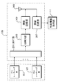
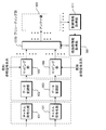
- FIG. 2 is a block diagram showing a configuration of the base station apparatus 1 according to the first embodiment of the present invention.
- the base station apparatus 1 includes a channel coding unit 101, a data modulation unit 103, a mapping unit 105, a precoding unit 107A (hereinafter referred to as precoding units 107A, 107B, 107C,... Are also represented as a precoding unit 107), an antenna unit 109, a control information acquisition unit 111, and an interference information acquisition unit 113.
- precoding units 107A hereinafter referred to as precoding units 107A, 107B, 107C,... Are also represented as a precoding unit 107
- an antenna unit 109 There are as many precoding units 107A as the number of subcarriers Nc .
- the transmission data sequence addressed to the terminal device 3 is subjected to channel coding in the channel coding unit 101 and then subjected to digital data modulation such as QPSK and 16QAM in the data modulation unit 103.
- An output from the data modulation unit 103 is input to the mapping unit 105.
- the mapping unit 105 performs mapping (also referred to as scheduling or resource allocation) in which each data is allocated to a designated radio resource (also referred to as resource element or simply resource).
- the radio resource here mainly refers to frequency and time.
- the radio resource to be used is determined based on reception quality or the like observed by the terminal device 3. In the present embodiment, it is assumed that radio resources to be used are determined in advance and can be grasped by both the base station device 1 and the terminal device 3.
- mapping section 105 a known reference signal sequence for performing propagation path estimation in terminal apparatus 3 is also multiplexed.
- the reference signals addressed to the terminal device 3 are multiplexed so as to be orthogonal to each other so that the received terminal device 3 can be separated from the data signal.
- the demodulation reference signal which is a specific reference signal for demodulation
- another reference signal may be further multiplexed. It is assumed that DMRS is periodically transmitted for each of time and frequency resources.
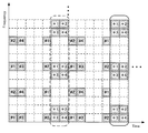
- FIG. 3 is a diagram showing an example of resource allocation of DMRS and data signal in the first embodiment of the present invention.
- the horizontal axis represents time (OFDM signal number), and the vertical axis represents frequency (subcarrier number).
- FIG. 3 shows a part of all radio resources, it can be considered that this arrangement is repeated in the time and frequency directions.
- a DMRS is transmitted in a resource qualified by a network line, but a DMRS surrounded by a broken line (hereinafter referred to as a second DMRS) is a DMRS surrounded by a solid line (hereinafter referred to as a first DMRS).
- phase rotation according to a precoding method to be described later is performed. Details will be described later.
- the output of the mapping unit 105 is input to the corresponding subcarrier precoding unit 107A.
- the signal processing in the precoding unit 107A will be described later. In the following, signal processing for the output of the precoding unit 107A will be described first.
- the output of the precoding unit 107A for each subcarrier is input to the antenna unit 109 of the corresponding transmission antenna.
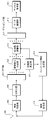
- FIG. 4 is a block diagram showing a device configuration of the antenna unit 109 according to the first embodiment of the present invention.
- the antenna unit 109 includes an IFFT unit 201, a GI insertion unit 203, a wireless transmission unit 205, a wireless reception unit 207, and an antenna 209.
- the output of the corresponding precoding unit 107A is input to the IFFT unit 201, and an Nc- point inverse fast Fourier transform (IFFT) or inverse discrete Fourier transform (IDFT) is applied to the Nc sub.
- IFFT inverse fast Fourier transform
- IDFT inverse discrete Fourier transform
- the output of the IFFT unit 201 is input to the GI insertion unit 203, and after being given a guard interval, is input to the wireless transmission unit 205.
- the wireless transmission unit 205 the baseband transmission signal is converted into a radio frequency (Radio Frequency (RF)) transmission signal.
- RF Radio Frequency
- the wireless reception unit 207 receives information associated with the interference signal estimated by the terminal device 3 and outputs the information to the control information acquisition unit 111.
- Precoding unit 107A Signal processing performed in precoding section 107A will be described. In the following, the k-th subcarrier precoding unit 107A will be described, and first, the case where the data signal component of the output of the mapping unit 105 is input will be described.
- FIG. 5 is a block diagram showing a device configuration of the precoding unit 107A according to the first embodiment of the present invention.
- the precoding unit 107A includes an interference suppression unit 301, a modulo calculation unit 303, a precoding switching unit 305, a switch 307A, a switch 307B, and a DMRS phase control unit 309.
- the precoding unit 107A includes the k-th subcarrier component ⁇ d (k) ⁇ of the output of the mapping unit 105 including transmission data addressed to the terminal device 3, and the interference signal ⁇ i (k) ⁇ received by the terminal device 3. Is entered.
- the interference signal ⁇ i (k) ⁇ is ideally acquired by the interference information acquisition unit 113, and the index k is omitted for simplicity.
- d-i. P x will change according to the interference signal i.
- P x is larger than a predetermined threshold value
- the switch 307A and the switch 307B are controlled so that the interference suppression unit 301 outputs the transmission code x toward the modulo arithmetic unit 303.
- P x is smaller than the threshold value, the switches 307A and 307B are controlled so that the transmission signal s is output from the interference suppression unit 301 toward the antenna unit 109.
- the threshold value can be determined in advance by computer simulation or the like.
- information regarding how the switch is switched is input to the DMRS phase control unit 309.
- the modulo operation unit 303 When the transmission code x is input to the modulo operation unit 303 from the precoding switching unit 305, the modulo operation unit 303 performs a modulo operation with a modulo width ⁇ on the transmission code x.
- Modulo operation mod ⁇ (x) with a modulo width ⁇ is a complex number in which the real part and the imaginary part are larger than ⁇ and smaller than ⁇ by adding an arbitrary Gaussian integer to an arbitrary input complex number x. Is an operation that returns. When expressed by an equation, it is expressed by equation (1).
- the average power of the modulo calculation output represented by the equation (1) is (2/3) ⁇ ⁇ 2 with respect to the average power of the original transmission data, a constant average is obtained regardless of the value of the interference power.
- ⁇ is not limited to anything as long as it is shared by the base station apparatus 1 and the terminal apparatus 3, but normally, the average bit value is the highest for a given transmission power.
- a value that reduces the error rate (Bit Error Rate (BER)) is selected. The value depends on the data modulation method applied to d, and is set to 2 1/2 for QPSK modulation and 4 ⁇ 10 ⁇ 1/2 for 16QAM, for example.
- BER Bit Error Rate
- the precoding switching unit 305 switches between linear precoding and nonlinear precoding based on the input transmission code power.
- the output of the modulo calculation unit 303 or the output of the interference suppression unit 301 is output toward the antenna unit 109 as the output of the precoding unit 107A.
- Pre-coding may be switched for each radio resource, but since the terminal device 3 needs to know which pre-coding has been performed, it is not desirable to switch the pre-coding in a very short cycle.
- precoding is switched in units of resource blocks (Resource block (RB)) in which 168 radio resources composed of 12 subcarriers included in the 14 OFDM symbols shown in FIG.
- RB resource block
- the number of resources included in the RB is not limited to this.
- Whether linear precoding or non-linear precoding is used is determined according to the power of the interference signal. If the interference signal varies in the time or frequency direction, the precoding scheme will also change in the time or frequency direction. In the applied precoding scheme, the signal demodulation method of the terminal device 3 to be described later changes, so the terminal device 3 needs to know which precoding is performed. Therefore, in the present embodiment, the terminal device 3 can grasp which precoding scheme is applied by changing the phase of the signal sequence used for the DMRS transmitted to the terminal device 3.
- DMRS Downlink Reference Signal
- the signal series used according to the pre-coding system applied to a data signal component is changed.
- the DMRS phase control unit 309 determines the amount of phase rotation to be given to the second DMRS based on the information about the precoding scheme applied to the transmission data input from the precoding switching unit 305, and interferes with the information. Input to the suppression unit 301.
- the interference suppression unit 301 performs phase rotation on the second DMRS based on information input from the DMRS phase control unit 309.
- the precoding method is linear precoding
- CDMRS is used as it is as a signal sequence.
- the signal sequence is a sequence obtained by applying phase rotation to CDMRS by ⁇ ⁇ c 1 , ⁇ c 2 , c 3 , ⁇ c 4 . . .
- C Np ⁇ may be used as a signal sequence.
- the phase rotation amount is ⁇ , but any phase rotation amount may be used as long as both the base station device 1 and the terminal device 3 are known.
- the signal sequence length may be an arbitrary length.
- the DMRS is for estimating information (propagation path information) for the terminal device 3 to demodulate a desired signal from a received signal.
- the information that the terminal device 3 wants to estimate is a power normalization term multiplied by the transmission signal. Therefore, if the DMRS that is a known signal is subjected to the same interference suppression processing as the data signal in the precoding unit 107A, the terminal device 3 can estimate the power normalization term.
- the precoding switching unit 305 determines whether or not to apply phase rotation to the CDMRS . However, when nonlinear precoding is performed, a modulo operation is also performed on DMRS.
- the power normalization term cannot be correctly estimated. Therefore, DMRS is transmitted by linear precoding even if non-linear precoding is applied to the data signal. At this time, since the power normalization term needs to be the same as that of the data signal, the transmission power of the DMRS slightly increases as compared with the data signal. In addition, if the terminal device 3 can correctly estimate the perturbation term added to the DMRS by another method, the DMRS may be subjected to nonlinear precoding.
- the ratio of the first DMRS and the second DMRS in the total radio resources is the same, but the ratio of the two does not necessarily have to be common.
- power normalization is not necessarily performed for each radio resource, and normalization may be performed such that the average transmission power for each of a plurality of radio resources (for example, every 1 RB) is constant.
- FIG. 6 is a block diagram showing a configuration of the terminal device 3 according to the first embodiment of the present invention.
- the terminal device 3 includes an antenna 401, a radio reception unit 403, a GI removal unit 405, an FFT unit 407, a reference signal separation unit 409, a propagation path estimation unit 411, and a feedback information generation unit. 413, a wireless transmission unit 414, a propagation path compensation unit 415, a demapping unit 417, a data demodulation unit 419, and a channel decoding unit 421.
- a signal received by the antenna 401 is input to the wireless reception unit 403 and converted into a baseband signal.
- the signal converted into the baseband is input to the GI removal unit 405, and after the guard interval is removed, is input to the FFT unit 407.
- N c point fast Fourier transform (FFT) or discrete Fourier transform (DFT) is applied to the input signal to convert it into N c subcarrier components.
- the output of the FFT unit 407 is input to the reference signal separation unit 409.
- the reference signal separation unit 409 separates the input signal into a data signal component and a DMRS component.
- the data signal component is output toward the propagation path compensation unit 415, and the DMRS is output toward the propagation path estimation unit 411.
- the signal processing described below is basically performed for each subcarrier.
- the propagation path estimation unit 411 performs propagation path estimation based on the input DMRS that is a known reference signal, and also estimates the precoding scheme currently applied by the base station apparatus 1.
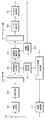
- FIG. 7 is a flowchart for explaining signal processing for DMRS in the propagation path estimation unit 411 according to the first embodiment of the present invention. Below, the signal processing with respect to DMRS is demonstrated based on the flowchart as described in FIG.
- the propagation path estimation unit 411 first performs propagation path estimation based on the first DMRS (step S101). Since the DM DMRS is used as the signal sequence for the first DMRS, the channel information H can be estimated by performing inverse modulation with the CDMRS .
- the propagation path estimation unit 411 performs inverse modulation on the radio resource in which the second DMRS is received based on the respective sequences, and performs two propagation path estimation values H LP and H NLP .
- a propagation path estimated value is calculated (step S102 and step S103).
- the information representing the error may be any information, but for example, the square error between H LP and H may be calculated.
- a mean square error between H LP and H estimated in plural may be calculated.
- step S105: YES it is determined that the precoding scheme used is linear precoding; otherwise (step S105: NO), the precoding scheme is Judge as non-linear precoding.
- the propagation path information estimated by the first and second DMRSs and the estimation result of the precoding scheme are output to the propagation path compensation section 415 as the output of the propagation path estimation section 411.
- Step S106 and Step S107 For example, when it is determined that the precoding is linear, the final channel estimation value is output using H and HLP . What averaged both may be sufficient, and what is necessary is just to output the result of applying some kind of interpolation. If it is determined that the precoding is nonlinear, the final channel estimation value is output from H and H NLP .
- the channel estimation unit 411 when the reception power is extremely small and, if the calculated error (the difference between the delta LP and delta NLP) is extremely small, the estimation accuracy of the precoding scheme, becomes extremely poor. Therefore, when the difference between the advance than determined threshold and delta LP delta NLP is small, the channel estimation unit 411, a precoding scheme applied to the data signal be determined that is a non-linear precoding good. As already described, if the terminal device 3 does not demodulate the signal by an appropriate demodulation method determined for each precoding scheme, the transmission characteristics are degraded.
- the amount of degradation in transmission characteristics when a signal with linear precoding is demodulated as a signal with nonlinear precoding is demodulated by assuming that a signal with nonlinear precoding has been subjected to linear precoding. This is smaller than the amount of degradation of transmission characteristics. Therefore, when the precoding scheme estimation accuracy is extremely poor, more stable transmission characteristics can be obtained by performing signal demodulation assuming that nonlinear precoding is always performed.
- the propagation path estimation unit 411 also performs interference signal estimation.
- a part of radio resources (carrier holes) that do not transmit any signal from the base station apparatus 1 are set, or a known reference signal that is not precoded separately from the DMRS is transmitted. It is possible to estimate.
- the estimated interference signal is output to feedback information generation section 413 and converted into a signal that can be reported to base station apparatus 1.
- the estimated interference signal may be quantized with a finite number of bits, or the estimated interference signal may be transmitted as it is as a transmission signal.
- the output of the feedback information generation unit 413 is sent to the radio transmission unit 414 and finally transmitted to the base station apparatus 1.
- the above is signal processing in the propagation path estimation unit 411.
- the data signal component, the channel estimation value estimated by the channel estimation unit 411, and the precoding scheme estimation value are input to the channel compensation unit 415.
- the channel compensation unit 415 first performs channel equalization processing using the channel estimation value.
- the channel equalization process may be performed by simple synchronous detection that divides the propagation path estimated value from the received signal. After the channel equalization processing is performed, signal processing based on the precoding scheme estimation result is performed.
- the channel equalized signal is output as it is to the demapping unit 417 as the output of the propagation path compensation unit 415.
- a modulo operation with the same modulo width as the modulo operation performed by the precoding unit 107A of the base station apparatus 1 is performed on the channel equalized signal.
- the modulo calculation result is output to the demapping unit 417 as the output of the propagation path compensation unit 415.
- the terminal device 3 extracts transmission data addressed to itself from radio resources used for transmission of transmission data addressed to itself.
- the output of the reference signal separation unit 409 may be input to the demapping unit 417 first, and only the radio resource component corresponding to the own device may be input to the propagation path compensation unit 415.
- the output of demapping section 417 is then input to data demodulating section 419 and channel decoding section 421, where data demodulation and channel decoding are performed.
- the propagation path estimation unit 411 estimates that the nonlinear precoding is performed in the base station apparatus 1, the propagation path compensation unit 415 does not perform the modulo operation, and which of the precoding methods is used. Is input to the channel decoding unit 421.
- the channel decoding unit 421 may determine the channel decoding method based on the precoding method estimation result.
- OFDM signal transmission is performed and precoding is performed for each subcarrier, but there is no limitation on the transmission scheme (or access scheme) and the precoding application unit.
- the present embodiment is also applicable when precoding is performed for each resource block in which a plurality of subcarriers are grouped.
- a single carrier-based access scheme for example, single carrier frequency division multiple access (SC- (FDMA) method.
- the terminal apparatus 3 can correctly grasp the precoding method that is actually applied without notifying the control information. Therefore, it is possible to correctly demodulate a desired signal from the received signal.
- the base station device 1 and the terminal device 3 are each targeted for one-to-one transmission.
- the second embodiment is directed to multi-user MIMO (MU-MIMO) transmission in which a base station apparatus having a plurality of transmission antennas and a plurality of terminal apparatuses perform simultaneous communication using the same radio resource.
- MU-MIMO multi-user MIMO
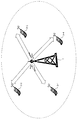
- FIG. 8 is a diagram showing an outline of a radio communication system according to the second embodiment of the present invention.
- a terminal apparatus that has N t transmitting antennas and has one receiving antenna for a base station apparatus (radio transmitting apparatus) 1 that can perform linear precoding and nonlinear precoding.
- the base station apparatus 1 acquires propagation path information to each terminal apparatus 3 from the control information notified from each terminal apparatus 3, and performs precoding for each subcarrier on transmission data based on the propagation path information.
- the number of reception antennas of the terminal device 3 is not limited to one.
- the number of data streams (also referred to as the rank number) transmitted to each terminal apparatus 3 is 1.
- the present embodiment includes a case where the rank number is 2 or more.
- CSI Channel State Information
- a quasi-static frequency selective fading channel is assumed.
- FIG. 9 is a block diagram showing a configuration of the base station apparatus 1 according to the second embodiment of the present invention.
- the base station apparatus 1 includes a channel encoding unit 101, a data modulation unit 103, a mapping unit 105, a precoding unit 107B, an antenna unit 109, a control information acquisition unit 111, a propagation path An information acquisition unit 501 is included.
- Precoding section 107B exists for the number of subcarriers N c
- antenna section 109 exists for the number of transmission antennas N t .
- the transmission data sequence addressed to each terminal apparatus 3 is subjected to channel coding in channel coding section 101 and then subjected to digital data modulation such as QPSK and 16QAM in data modulation section 103.
- An output from the data modulation unit 103 is input to the mapping unit 105.
- the mapping unit 105 similarly to the first embodiment, the transmission data and the unique reference signal are respectively mapped to appropriate radio resources.
- the mapping unit 105 is directed to a plurality of terminal devices 3.
- DMRS unique reference signal
- CRS Cell-specific reference signal
- CRS is a reference signal that is basically transmitted without precoding.
- such a reference signal is also referred to as a sounding signal).
- the method for multiplexing CRS and DMRS is not particularly limited.
- the CRS is arranged so as to be orthogonal between the transmission antennas
- the DMRS is arranged so as to be orthogonal between the connected terminal apparatuses 3.
- any of time orthogonal, frequency orthogonal, spatial orthogonal, code orthogonal, or a combination of a plurality of orthogonal techniques can be considered.
- the data signal and the reference signal are assumed to be orthogonal to each other in time and frequency, and the terminal device 3 will be described assuming that desired information can be ideally estimated.
- the DMRS addressed to the u-th terminal device 3-u is originally intended to estimate information meaningful only to the u-th terminal device 3-u.
- the other terminal device 3 can grasp the DMRS addressed to the u-th terminal device 3-u.
- the terminal device 3 can perform IUI suppression processing such as an interference canceller in a propagation path compensation unit described later.
- IUI suppression processing such as an interference canceller in a propagation path compensation unit described later.
- detailed description of the interference canceller is omitted.
- the phase rotation given to the signal sequence is changed according to the precoding method described later. Details will be described later.
- the output of the mapping unit 105 is input to the corresponding subcarrier precoding unit 107B.
- the signal processing in the precoding unit 107B will be described later.
- the signal processing for the output of the precoding unit 107B will be described first.
- the output of precoding section 107B for each subcarrier is input to antenna section 109 of the corresponding transmission antenna.
- the device configuration of the antenna unit 109 according to the present embodiment is the same as the device configuration shown in FIG. 4 and the signal processing being performed is substantially the same, and thus the description thereof is omitted.
- a plurality of antenna units 109 exist, and what is output toward the control information acquisition unit 111 is not information associated with the interference signal, but is expressed by Equation (2).
- the information associated with the given propagation path information is different from the antenna unit 109 of the first embodiment.
- FIG. 11 is a block diagram showing a device configuration of the precoding unit 107B according to the second embodiment of the present invention.
- the precoding unit 107B includes a linear filter generation unit 601, a precoding switching unit 603, a perturbation vector search unit 605, a transmission signal generation unit 607, and a DMRS phase control unit 609. It is configured. First, signal processing when a data signal is input to the precoding unit 107B will be described.
- the k-th subcarrier component ⁇ d u (k); u 1 to U ⁇ of the output of the mapping unit 105 including the transmission data addressed to each terminal device 3 and the k-th output of the propagation path information acquisition unit 501
- a subcarrier propagation path matrix H (k) is input.
- H (k) is estimated by the terminal device 3 based on the above-described CRS and notified to the base station device 1. In the following description, it is assumed that H (k) is ideally acquired by the propagation path information acquisition unit 501, and the index k is omitted for simplicity.
- the precoding unit 107B calculates a linear filter W for suppressing IUI.
- the calculation method of W is not limited to anything.
- a linear filter based on zero forcing (ZF) that completely suppresses IUI may be calculated.
- IAI inter-antenna interference
- a linear filter that suppresses both IUI and IAI, or a linear filter that suppresses only IUI or only IAI may be used.
- the perturbation vector search unit 605 searches for a perturbation term.
- the perturbation term search method is determined in accordance with the desired transmission quality and the amount of computation that can be realized by the arithmetic unit included in the base station apparatus 1. For example, when using Vector perturbation (VP) that can achieve the highest reception quality, the perturbation term can be obtained by solving the minimization problem expressed by Equation (3).
- VP Vector perturbation
- z t [z t, 1 ,. . . , Z t, U ] T
- z t, u is a perturbation term added to the transmission data addressed to the u th terminal apparatus 3-u.
- Equation (3) assumes a case where all the terminal devices 3 connected to the base station device 1 can perform a modulo calculation. However, in an actual system, there may be a mixture of terminals that support the modulo operation and terminals that do not support it. Adding the perturbation term is effective for maximizing the channel capacity of the entire system, but may not necessarily maximize the channel capacity that each terminal device 3 can achieve. For example, in an environment where the data modulation method is QPSK and the received signal-to-noise power ratio (SNR) is relatively small, it is better not to add the perturbation term. It is reported that it can be taken. In other words, it is more effective in improving the frequency utilization efficiency to control not to add the perturbation term to some transmission data without adding the perturbation term to all the transmission data addressed to each terminal device 3. It means that there may be.
- SNR received signal-to-noise power ratio
- the precoding switching unit 603 controls whether or not a perturbation term should be added to each terminal device 3. For example, processing such as control is performed so that a perturbation term is not added to transmission data addressed to the terminal device 3 that uses QPSK modulation as the data modulation method.
- linear precoding may be performed on all terminal apparatuses 3 in a certain RB, and non-linear precoding may be performed on all terminal apparatuses 3 in another RB.
- Precoding information applied to the transmission data is input to the perturbation vector search unit 605 and the DMRS phase control unit 609. In the following description, it is described that linear precoding is applied to the terminal device 3 in which the perturbation term is not added to the transmission data, and nonlinear precoding is applied to the terminal device 3 in which the perturbation term is added. It will be described.
- ⁇ is a power normalization term for making the transmission power constant. Power normalization may be performed in any radio resource unit, but power normalization is performed so that the average transmission power of a certain number of radio resources is constant for precoding to DMRS described later. Is desirable. In the following, it is assumed that power normalization is also performed for each RB, which is a unit for switching precoding.
- DMRS spatial multiplexing is not performed, so precoding basically performs only multiplication of the linear filter W, and the perturbation term No addition is performed.
- the power normalization is performed together with the data signal. Note that spatial multiplexing may also be performed for DMRS, but in this case, each terminal device 3 can estimate the perturbation term added to DMRS, or the perturbation term should not be added. Need to control.
- the signal sequence of the second DMRS is determined depending on whether or not a perturbation term is added to the data signal. Is controlled to give a phase rotation. Specifically, phase rotation is not given to DMRS transmitted to the terminal device 3 in which linear precoding is applied to the data signal. On the other hand, the DMRS transmitted to the terminal device 3 in which nonlinear precoding is applied to the data signal is controlled so as to give a certain phase rotation.
- the phase rotation amount to be given may be ⁇ as in the first embodiment, but an arbitrary value may be given. However, the amount of phase rotation needs to be shared between the base station device 1 and each terminal device 3. If sharing is performed, the phase rotation amount may be changed in each terminal device 3. Further, it may be controlled to change the amount of phase rotation given for each RB.
- the DMRS subjected to precoding and power normalization is output toward the antenna unit 109 in the same manner as the data signal.
- the CRS is transmitted without any precoding.
- the power normalization may be performed in the same manner as the data signal or DMRS.
- terminal device 3 Since the device configuration of the terminal device 3 according to the second embodiment is the same as that in FIG. 6 and the signal processing in each device is substantially the same as that in the first embodiment, description thereof is omitted. However, a new CRS is input to the propagation path estimation unit 411. The propagation path estimation unit 411 estimates propagation path information (see Expression (2)) based on the received CRS, and inputs the estimation result to the feedback information generation unit 413. The feedback information generation unit 413 converts the input propagation path estimation value into a signal that can be notified to the base station apparatus 1. Eventually, the data is transmitted from the wireless transmission unit 414 toward the base station apparatus 1.
- the method for generating feedback information is not limited to anything.
- the propagation path estimation value may be directly quantized with a finite number of bits, digitally modulated, and transmitted. You may notify using the code book shared between the terminal devices 3. FIG.
- the phase rotation is not applied to the DMRS as described above, but the phase rotation is applied to the sounding signal such as CRS.
- the precoding scheme is estimated by comparing the error of the propagation path information estimated from the CRS that has been subjected to phase rotation only for some CRSs and that has not been subjected to phase rotation, and the CRSs that have undergone phase rotation. It becomes possible to do.
- a plurality of precoding schemes are selectively used for MU-MIMO transmission in which communication is performed simultaneously with a plurality of terminal devices 3 connected to the base station device 1.
- a method of accurately notifying each terminal apparatus 3 of the applied precoding scheme by changing the phase rotation amount of the DMRS in transmission performed simultaneously is targeted.
- two examples of linear precoding and nonlinear precoding have been described as examples of a plurality of precoding.
- the precoding targeted by the present invention is limited to this combination. is not.
- precoding is performed so that the channel equalization process performed in the propagation path compensation unit 415 of the terminal apparatus 3 can be performed by simple synchronous detection.
- precoding for example, a block diagonalization method that requires spatial detection processing.
- the target of the present embodiment is that when various precodings are selectively or simultaneously used in this way, the precoding that the terminal apparatus 3 is currently applied by which phase rotation is given to the DMRS. It is a wireless communication system that grasps whether or not there is.
- the phase rotation amount given to the DMRS and the precoding method may be associated with each other. For example, when three of A, B, and C are applicable as precoding, phase rotation is not given in the case of precoding A, phase rotation of ⁇ / 2 is given in case of B, and in case of C, A phase rotation of 3 ⁇ / 2 may be given.
- the propagation path estimation unit 411 of the terminal device 3 calculates a propagation path estimated value in consideration of all possible phase rotation amounts for the second DMRS, and the propagation path estimated by the first DMRS. It is possible to grasp which precoding has been performed by calculating an error from the estimated value.
- the second embodiment a case where a plurality of precodings are selectively or simultaneously performed for MU-MIMO transmission is targeted. According to the present embodiment, it is possible to add a new precoding method while maintaining backward compatibility, so that it is possible to contribute to the advancement of a wireless communication system, and thus to improve the frequency utilization efficiency. Can contribute.
- the case where the terminal device 3 grasps which precoding is applied to the received signal based on the amount of phase rotation given to the DMRS has been targeted.
- This can be understood as transmitting information other than the propagation path information from the base station apparatus 1 to the terminal apparatus 3 using DMRS, which is originally intended to estimate the propagation path state information.
- the third embodiment is directed to a case in which arbitrary information is notified using DMRS phase information.
- the configuration of the base station apparatus 1 is the same as that of the first and second embodiments, and the only difference is that the precoding unit 107 becomes the precoding unit 107C. Therefore, the third embodiment will be described below. The signal processing in the precoding unit 107C according to will be described.
- FIG. 12 is a block diagram showing a device configuration of a precoding unit 107C according to the third embodiment of the present invention.
- the precoding unit 107C includes a linear filter generation unit 601, a precoding switching unit 603, a perturbation vector search unit 605, a transmission signal generation unit 607, and a DMRS phase control unit 701.
- the signal processing of each device is the same as in FIG. 11 except for the DMRS phase control unit 701, and the signal processing when a data signal is input is substantially the same as in the second embodiment, and thus the description is omitted ( When a data signal is input, the DMRS phase control unit 701 does not perform any signal processing).
- the precoding switching unit 603 may be omitted.
- the perturbation vector search unit 605 may be controlled not to search for the perturbation term at all, that is, to perform linear precoding.
- ⁇ is white Gaussian noise applied to each received signal.
- the data signal is subjected to nonlinear precoding, while DMRS is transmitted without performing spatial multiplexing.
- the terminal device 3 estimates the power normalization term ⁇ by dividing p u which is a known signal from ru and DMRS, and divides ⁇ from ru and DATA using the estimation result. Thereafter, the desired signal du is demodulated by performing a modulo operation.
- the DMRS may be given arbitrary phase rotation without being shared between the base station apparatus 1 and the terminal apparatus 3.
- the information to be estimated from ru , DATA is not only the power normalization term ⁇ , but also the propagation path information that has changed from the feedback of the propagation path information until the data signal is received. It also includes information on the components and the phase rotation that occurs because the frequencies of the oscillators of the base station device 1 and the terminal device 3 are different. In the following, based on this, a method for notifying the terminal device 3 of arbitrary information from the phase rotation information given to the DMRS will be described.
- the one shown in FIG. 10 taken as an example in the second embodiment is used.
- the reason will be described later it is actually desirable that the first DMRS and the second DMRS exist in the same OFDM signal.
- the DMRS phase control unit 701 applies phase rotation to the DMRS based on information that the base station device 1 wants to send to each terminal device 3.
- the method of giving the phase rotation is not limited to anything in the present invention, but for example, the same modulation as QPSK modulation may be performed. That is, according to the resource allocation given as an example in the present embodiment, since the second DMRS has 6 radio resources secured per RB for each terminal device 3, QPSK modulation is performed for each. If the applied signal is transmitted, 6-bit information can be notified. Since other signal processing such as power normalization is the same as that of the first DMRS, description thereof is omitted.
- FIG. 13 is a block diagram showing the configuration of the terminal device 3 according to the third embodiment of the present invention.
- the terminal device 3 includes an antenna 401, a radio reception unit 403, a GI removal unit 405, an FFT unit 407, a reference signal separation unit 409, a propagation path estimation unit 801, and feedback information generation. 413, radio transmission section 414, propagation path compensation section 415, demapping section 417, data demodulation section 419, channel decoding section 421, and information demodulation section 803.
- the configuration of the terminal device 3 is substantially the same as in FIG. 6 and the signal processing performed in each device is also substantially the same. Only the signal processing in the propagation path estimation unit 801 and the information demodulation unit 803 will be described.
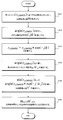
- FIG. 14 is a flowchart for explaining signal processing when DMRS is input in the propagation path estimation unit 801 of the terminal device 3 according to the third embodiment of the present invention.
- the signal processing in the propagation path estimation part 801 is demonstrated based on FIG. Since signal processing when CRS is input is the same as that of the propagation path estimation unit 411 in the second embodiment, description thereof is omitted.
- the propagation path estimation value H is acquired based on the first DMRS (step S201).
- the received signal of the u-th terminal apparatus 3-u when the first DMRS is received is given by Equation (5).
- description of the noise component will be omitted.
- the propagation path estimation value H is given by ⁇ ⁇ ⁇ ′ ⁇ exp (j ⁇ ).
- angle ( ru, DMRS1 ) is calculated, and the phase fluctuation component exp (j ⁇ ) is estimated (step S202).
- Equation (6) The received signal of the second DMRS of the u-th terminal device 3-u is given by Equation (6).
- ⁇ u is a phase rotation amount determined based on information that the base station apparatus 1 wanted to notify the u-th terminal apparatus 3-u, and is unknown information to the u-th terminal apparatus 3-u.
- the second received signal r u of DMRS, DMRS2 by multiplying the exp (-j.phi.)
- the received signal r u from the removed phase fluctuation component , DMRS2 ′ is calculated (step S203). Since the phase fluctuation component is a value that fluctuates with time, in order for this signal processing to be performed with high accuracy, the first DMRS and the second DMRS are radio resources that have as high a time correlation as possible. It is desirable to be transmitted.
- ⁇ u is estimated by calculating angle ( ru, DMRS2 ′) (step S204).
- the information demodulating unit 803 extracts information from ⁇ u by a method previously determined between the base station device 1 and each terminal device 3. For example, in a communication system in which a plurality of precodings are selectively or simultaneously used as in the first and second embodiments, the value of ⁇ u and the data signal addressed to each terminal device 3 are used. A method of associating precoding methods is conceivable. In this case, the output of the information demodulating unit 803 is output toward the propagation path compensation unit 415 or the channel decoding unit 421 (FIG. 13 shows a case where it is output toward the propagation path compensation unit 415.
- the base station device 1 can transmit arbitrary information to each terminal device 3, and in this case, The output of the information demodulator 803 is output as information addressed to the u-th terminal device 3 as it is.
- the above is the signal processing for the DMRS in the propagation path estimation unit 801 and the information demodulation unit 803 according to the third embodiment. If the time correlation between radio resources in which the first DMRS and the second DMRS are transmitted is sufficiently large and the reception SNR is sufficiently large, each of the base stations from the base station apparatus 1 by the second DMRS. Arbitrary information bits can be newly notified to the terminal device 3.
- Channel coding can also be performed on information bits transmitted by the second DMRS, and channel coding may be performed together with information bits originally transmitted as data signals.
- the precoding method or the like is notified by the second DMRS, it is suggested that the signal processing in the propagation path compensation unit 415 is not performed until channel decoding is performed. Therefore, when notifying control information, it is desirable to perform error control by a simple method that does not cause much decoding delay, such as transmitting the same signal multiple times.
- the case where an arbitrary information bit is notified from the base station apparatus 1 to each terminal apparatus 3 by the second DMRS is targeted.
- the program that operates in the mobile station apparatus and the base station apparatus 1 related to the present invention is a program (a program that causes a computer to function) that controls the CPU and the like so as to realize the functions of the above-described embodiments related to the present invention.
- Information handled by these devices is temporarily stored in the RAM at the time of processing, then stored in various ROMs and HDDs, read out by the CPU, and corrected and written as necessary.
- a recording medium for storing the program a semiconductor medium (for example, ROM, nonvolatile memory card, etc.), an optical recording medium (for example, DVD, MO, MD, CD, BD, etc.), a magnetic recording medium (for example, magnetic tape, Any of a flexible disk etc. may be sufficient.
- the processing is performed in cooperation with the operating system or other application programs.
- the function of the invention may be realized.
- the program when distributing to the market, can be stored in a portable recording medium for distribution, or transferred to a server computer connected via a network such as the Internet.
- the storage device of the server computer is also included in the present invention.
- LSI which is typically an integrated circuit.
- Each functional block of the mobile station apparatus and the base station apparatus 1 may be individually made into a processor, or a part or all of them may be integrated into a processor.
- the method of circuit integration is not limited to LSI, and may be realized by a dedicated circuit or a general-purpose processor.
- an integrated circuit based on the technology can also be used.
Abstract
La présente invention porte sur un système de communication sans fil dans lequel une pluralité de précodages sont sélectivement ou simultanément utilisés, le système identifiant si un dispositif terminal effectue bien un précodage sans augmentation du surdébit. Un dispositif de précodage utilisé dans un dispositif d'émission sans fil pour réaliser une transmission sans fil avec un dispositif de réception sans fil est décrit, dans lequel un signal de données et une pluralité de types de signaux de référence caractéristiques sont soumis à un précodage sur la base d'informations de commande acquises en provenance du récepteur sans fil, une rotation de phase est communiquée à chacun des types de signaux de référence caractéristiques, et la valeur de rotation de phase de la rotation de phase est corrélée à des informations devant être notifiées au dispositif de réception sans fil.
Priority Applications (1)
| Application Number | Priority Date | Filing Date | Title |
|---|---|---|---|
| US14/382,855 US20150023279A1 (en) | 2012-03-06 | 2013-03-04 | Pre-coding device, wireless transmission device, wireless receiving device, wireless communication system, and integrated circuit |
Applications Claiming Priority (2)
| Application Number | Priority Date | Filing Date | Title |
|---|---|---|---|
| JP2012-049149 | 2012-03-06 | ||
| JP2012049149A JP5908307B2 (ja) | 2012-03-06 | 2012-03-06 | プリコーディング装置、無線送信装置、無線受信装置、無線通信システムおよび集積回路 |
Publications (1)
| Publication Number | Publication Date |
|---|---|
| WO2013133192A1 true WO2013133192A1 (fr) | 2013-09-12 |
Family
ID=49116670
Family Applications (1)
| Application Number | Title | Priority Date | Filing Date |
|---|---|---|---|
| PCT/JP2013/055784 WO2013133192A1 (fr) | 2012-03-06 | 2013-03-04 | Dispositif de précodage, dispositif d'émission sans fil, dispositif de réception sans fil, système de communication sans fil et circuit intégré |
Country Status (3)
| Country | Link |
|---|---|
| US (1) | US20150023279A1 (fr) |
| JP (1) | JP5908307B2 (fr) |
| WO (1) | WO2013133192A1 (fr) |
Families Citing this family (12)
| Publication number | Priority date | Publication date | Assignee | Title |
|---|---|---|---|---|
| JP2016157992A (ja) * | 2013-07-04 | 2016-09-01 | シャープ株式会社 | 端末装置、基地局装置および送信方法 |
| JP2017022427A (ja) * | 2013-11-07 | 2017-01-26 | シャープ株式会社 | 通信システム、基地局装置、および端末装置 |
| WO2018048055A2 (fr) * | 2016-09-08 | 2018-03-15 | 엘지전자 주식회사 | Procédé d'estimation de rotation de phase de port de transmission dans un système de communication sans fil et appareil associé |
| US10411914B2 (en) | 2016-12-14 | 2019-09-10 | Intel IP Corporation | Data detection in MIMO systems with demodulation and tracking reference signals |
| WO2018142506A1 (fr) * | 2017-02-01 | 2018-08-09 | 三菱電機株式会社 | Dispositif de transmission, dispositif de réception, station de base, terminal et procédé de transmission |
| JP7227233B2 (ja) * | 2018-05-10 | 2023-02-21 | 株式会社Nttドコモ | 受信装置 |
| CN108880637B (zh) * | 2018-07-27 | 2020-11-13 | 电子科技大学 | 基于码本的多符号联合旋转thp预编码方法 |
| CN112544046B (zh) * | 2018-07-27 | 2022-12-23 | 上海诺基亚贝尔股份有限公司 | 用于发送解调参考信号的装置和方法 |
| JP7284445B2 (ja) * | 2020-03-19 | 2023-05-31 | 日本電信電話株式会社 | 無線通信方法及び無線通信システム |
| CN114499600B (zh) * | 2020-11-12 | 2023-04-18 | 华为技术有限公司 | 多用户预编码方法、装置及设备 |
| US11463134B2 (en) * | 2021-02-11 | 2022-10-04 | Nxp Usa, Inc. | Secure Wi-Fi communication by perturbation of a spatial mapping matrix |
| WO2023238687A1 (fr) * | 2022-06-07 | 2023-12-14 | ソニーグループ株式会社 | Dispositif d'antenne et dispositif sans fil |
Citations (5)
| Publication number | Priority date | Publication date | Assignee | Title |
|---|---|---|---|---|
| WO2007049760A1 (fr) * | 2005-10-28 | 2007-05-03 | Matsushita Electric Industrial Co., Ltd. | Dispositifs et procedes d’emission et de reception, et systeme de communication sans fil |
| WO2010109518A1 (fr) * | 2009-03-24 | 2010-09-30 | 富士通株式会社 | Système de communication sans fil, dispositif de terminal, dispositif de station de base, procédé de communication sans fil dans un système de communication sans fil |
| JP2011146995A (ja) * | 2010-01-15 | 2011-07-28 | Sharp Corp | 通信システム、通信装置、通信方法およびそのプロセッサ |
| JP2013031132A (ja) * | 2011-07-29 | 2013-02-07 | Sharp Corp | 無線受信装置およびプログラム |
| JP2013042350A (ja) * | 2011-08-15 | 2013-02-28 | Sharp Corp | 無線送信装置、無線受信装置、プログラム、集積回路および無線通信システム |
Family Cites Families (25)
| Publication number | Priority date | Publication date | Assignee | Title |
|---|---|---|---|---|
| JPH09181701A (ja) * | 1995-12-26 | 1997-07-11 | Sharp Corp | スペクトル拡散通信方式 |
| US8320301B2 (en) * | 2002-10-25 | 2012-11-27 | Qualcomm Incorporated | MIMO WLAN system |
| DE10333514B4 (de) * | 2003-07-17 | 2005-10-13 | Siemens Ag | Nichtlineares Vorcodierungsverfahren für einen digitalen Broadcastkanal |
| JP4765322B2 (ja) * | 2005-01-21 | 2011-09-07 | ソニー株式会社 | 無線通信システム、無線通信装置及び無線通信方法、並びにコンピュータ・プログラム |
| CN101836410A (zh) * | 2007-10-31 | 2010-09-15 | 高通股份有限公司 | 使用时分多路复用导频在广播ofdm系统中的同步 |
| KR100932272B1 (ko) * | 2007-12-13 | 2009-12-16 | 한국전자통신연구원 | 멀티 유저 미모를 위한 송신 간섭 제거 방법 |
| JP5047834B2 (ja) * | 2008-02-15 | 2012-10-10 | 株式会社エヌ・ティ・ティ・ドコモ | 無線通信装置及び無線通信方法 |
| US20100041350A1 (en) * | 2008-08-13 | 2010-02-18 | Samsung Electronics, Co., Ltd. | Uplink transmissions with two antenna ports |
| RU2405252C2 (ru) * | 2009-01-21 | 2010-11-27 | Корпорация "САМСУНГ ЭЛЕКТРОНИКС Ко., Лтд." | Способ передачи-приема сигнала в многопользовательской системе радиосвязи с множеством передающих и множеством приемных антенн |
| GB2467143B (en) * | 2009-01-22 | 2011-04-06 | Toshiba Res Europ Ltd | Wireless commication method and apparatus |
| US8838051B1 (en) * | 2009-02-19 | 2014-09-16 | Qualcomm Incorporated | Transmitter beamforming power control |
| CN101854186B (zh) * | 2009-03-30 | 2015-04-01 | 三星电子株式会社 | 用于数据传输的预编/解码方法和系统 |
| EP2242187B1 (fr) * | 2009-04-14 | 2015-10-28 | Fraunhofer-Gesellschaft zur Förderung der angewandten Forschung e.V. | Procédé et dispositif pour le traitement de données dans un réseau de communication |
| WO2011016691A2 (fr) * | 2009-08-06 | 2011-02-10 | 엘지전자 주식회사 | Procédé et appareil d'émission de signaux montants dans un système de communication sans fil pour la prise en charge d'une transmission par antennes multiples |
| US8451944B2 (en) * | 2009-09-04 | 2013-05-28 | Hitachi, Ltd. | Tomlinson harashima precoding with additional receiver processing in a multi-user multiple-input multiple-output wireless transmission system |
| US8483265B2 (en) * | 2009-09-04 | 2013-07-09 | Hitachi, Ltd. | Generalized decision feedback equalizer precoder with input covariance matrix calculation for multi-user multiple-input multiple-output wireless transmission systems |
| JP4896196B2 (ja) * | 2009-10-01 | 2012-03-14 | 株式会社エヌ・ティ・ティ・ドコモ | 協調送信方法、協調送信システム、集約局及び無線基地局 |
| US9887754B2 (en) * | 2010-05-04 | 2018-02-06 | Qualcomm Incorporated | Method and apparatus for optimizing power distribution between symbols |
| US9124325B2 (en) * | 2010-06-21 | 2015-09-01 | Panasonic Intellectual Property Corporation Of America | Terminal apparatus, base station apparatus, retransmission method and resource allocation method |
| WO2012017818A1 (fr) * | 2010-08-02 | 2012-02-09 | シャープ株式会社 | Appareil de communication et système de communication |
| US8488529B2 (en) * | 2011-01-05 | 2013-07-16 | Telefonaktiebolaget Lm Ericsson (Publ) | Efficient information mapping for transmission grants |
| US20120182944A1 (en) * | 2011-01-19 | 2012-07-19 | Telefonaktiebolaget Lm Ericsson (Publ) | Methods and arrangements for signaling channel state information |
| WO2013022396A1 (fr) * | 2011-08-09 | 2013-02-14 | Telefonaktiebolaget L M Ericsson (Publ) | Procédé et agencement pour commande de puissance de liaison montante |
| JP5859786B2 (ja) * | 2011-09-16 | 2016-02-16 | シャープ株式会社 | 無線送信装置、無線受信装置、無線通信システム、プログラムおよび集積回路 |
| EP2817892B1 (fr) * | 2012-02-08 | 2017-07-19 | Telefonaktiebolaget LM Ericsson (publ) | Procédé et agencement destinés à permettre le réglage d'une émission à partir d'antennes corrélées |
-
2012
- 2012-03-06 JP JP2012049149A patent/JP5908307B2/ja active Active
-
2013
- 2013-03-04 US US14/382,855 patent/US20150023279A1/en not_active Abandoned
- 2013-03-04 WO PCT/JP2013/055784 patent/WO2013133192A1/fr active Application Filing
Patent Citations (5)
| Publication number | Priority date | Publication date | Assignee | Title |
|---|---|---|---|---|
| WO2007049760A1 (fr) * | 2005-10-28 | 2007-05-03 | Matsushita Electric Industrial Co., Ltd. | Dispositifs et procedes d’emission et de reception, et systeme de communication sans fil |
| WO2010109518A1 (fr) * | 2009-03-24 | 2010-09-30 | 富士通株式会社 | Système de communication sans fil, dispositif de terminal, dispositif de station de base, procédé de communication sans fil dans un système de communication sans fil |
| JP2011146995A (ja) * | 2010-01-15 | 2011-07-28 | Sharp Corp | 通信システム、通信装置、通信方法およびそのプロセッサ |
| JP2013031132A (ja) * | 2011-07-29 | 2013-02-07 | Sharp Corp | 無線受信装置およびプログラム |
| JP2013042350A (ja) * | 2011-08-15 | 2013-02-28 | Sharp Corp | 無線送信装置、無線受信装置、プログラム、集積回路および無線通信システム |
Non-Patent Citations (2)
| Title |
|---|
| HIROSHI NAKANO ET AL.: "Adaptive THP Scheme Control for Downlink MU-MIMO Systems", IEICE TECHNICAL REPORT, RCS2009-293, 24 February 2010 (2010-02-24), pages 203 - 208 * |
| YOUNG-HAN NAM ET AL.: "Evolution of Reference Signals for LTE-Advanced Systems", COMMUNICATIONS MAGAZINE, vol. 50, no. ISS. 2, February 2012 (2012-02-01), pages 132 - 138, XP011417049, DOI: doi:10.1109/MCOM.2012.6146492 * |
Also Published As
| Publication number | Publication date |
|---|---|
| JP5908307B2 (ja) | 2016-04-26 |
| JP2013187612A (ja) | 2013-09-19 |
| US20150023279A1 (en) | 2015-01-22 |
Similar Documents
| Publication | Publication Date | Title |
|---|---|---|
| JP5908307B2 (ja) | プリコーディング装置、無線送信装置、無線受信装置、無線通信システムおよび集積回路 | |
| US9008166B2 (en) | Filter calculating device, transmitting device, receiving device, processor, and filter calculating method | |
| JP6316205B2 (ja) | 基地局装置、端末装置、無線通信システムおよび集積回路 | |
| JP5596498B2 (ja) | 基地局装置、移動局装置及びそれらを用いた無線通信システム | |
| JP5804594B2 (ja) | プリコーディング装置、プリコーディング用プログラムおよび集積回路 | |
| US8731488B2 (en) | Wireless communication apparatus and method | |
| WO2014069262A1 (fr) | Dispositif de station de base, dispositif terminal et système de communication sans fil | |
| WO2014199989A1 (fr) | Appareil de station de base, appareil terminal, système de communication sans fil et circuit intégré | |
| Ruder et al. | Combined user pairing and spectrum allocation for multiuser SC-FDMA transmission | |
| WO2015186531A1 (fr) | Dispositif terminal, procédé de génération d'informations de rétroaction, et dispositif de station de base | |
| WO2014057840A1 (fr) | Dispositif terminal, dispositif station de base, système de communication sans fil, méthode de réception, et circuit intégré | |
| JP5859913B2 (ja) | 無線受信装置、無線送信装置、無線通信システム、プログラムおよび集積回路 | |
| WO2013018555A1 (fr) | Dispositif de réception sans fil et programme | |
| JP5641787B2 (ja) | 端末装置及びそれを用いた無線通信システム | |
| JP5546357B2 (ja) | 送信装置、受信装置、無線通信システム、制御プログラムおよび集積回路 | |
| WO2012157393A1 (fr) | Station de base, station mobile, programme de commande et circuit intégré | |
| WO2014122850A1 (fr) | Dispositif station de base, procédé de précodage, circuit intégré et système de radiocommunication | |
| JP5909104B2 (ja) | 無線送信装置、無線受信装置、無線通信システムおよびプリコーディング方法 | |
| JP6047744B2 (ja) | 無線通信システム、無線通信装置および無線通信方法 | |
| JP5753041B2 (ja) | 無線送信装置、無線受信装置、および無線通信システム | |
| JP2013123196A (ja) | プリコーディング装置、無線送信装置、プリコーディング方法、プログラムおよび集積回路 | |
| JP2013183394A (ja) | 無線通信システム、無線送信装置および無線通信方法 |
Legal Events
| Date | Code | Title | Description |
|---|---|---|---|
| 121 | Ep: the epo has been informed by wipo that ep was designated in this application |
Ref document number: 13757024 Country of ref document: EP Kind code of ref document: A1 |
|
| WWE | Wipo information: entry into national phase |
Ref document number: 14382855 Country of ref document: US |
|
| NENP | Non-entry into the national phase |
Ref country code: DE |
|
| 122 | Ep: pct application non-entry in european phase |
Ref document number: 13757024 Country of ref document: EP Kind code of ref document: A1 |