WO2012157393A1 - Station de base, station mobile, programme de commande et circuit intégré - Google Patents
Station de base, station mobile, programme de commande et circuit intégré Download PDFInfo
- Publication number
- WO2012157393A1 WO2012157393A1 PCT/JP2012/060435 JP2012060435W WO2012157393A1 WO 2012157393 A1 WO2012157393 A1 WO 2012157393A1 JP 2012060435 W JP2012060435 W JP 2012060435W WO 2012157393 A1 WO2012157393 A1 WO 2012157393A1
- Authority
- WO
- WIPO (PCT)
- Prior art keywords
- matrix
- propagation path
- base station
- terminal device
- unit
- Prior art date
Links
Images


Classifications
-
- H—ELECTRICITY
- H04—ELECTRIC COMMUNICATION TECHNIQUE
- H04B—TRANSMISSION
- H04B7/00—Radio transmission systems, i.e. using radiation field
- H04B7/02—Diversity systems; Multi-antenna system, i.e. transmission or reception using multiple antennas
- H04B7/04—Diversity systems; Multi-antenna system, i.e. transmission or reception using multiple antennas using two or more spaced independent antennas
- H04B7/06—Diversity systems; Multi-antenna system, i.e. transmission or reception using multiple antennas using two or more spaced independent antennas at the transmitting station
- H04B7/0613—Diversity systems; Multi-antenna system, i.e. transmission or reception using multiple antennas using two or more spaced independent antennas at the transmitting station using simultaneous transmission
- H04B7/0615—Diversity systems; Multi-antenna system, i.e. transmission or reception using multiple antennas using two or more spaced independent antennas at the transmitting station using simultaneous transmission of weighted versions of same signal
- H04B7/0619—Diversity systems; Multi-antenna system, i.e. transmission or reception using multiple antennas using two or more spaced independent antennas at the transmitting station using simultaneous transmission of weighted versions of same signal using feedback from receiving side
- H04B7/0621—Feedback content
- H04B7/0626—Channel coefficients, e.g. channel state information [CSI]
-
- H—ELECTRICITY
- H04—ELECTRIC COMMUNICATION TECHNIQUE
- H04B—TRANSMISSION
- H04B7/00—Radio transmission systems, i.e. using radiation field
- H04B7/02—Diversity systems; Multi-antenna system, i.e. transmission or reception using multiple antennas
- H04B7/04—Diversity systems; Multi-antenna system, i.e. transmission or reception using multiple antennas using two or more spaced independent antennas
- H04B7/0413—MIMO systems
- H04B7/0417—Feedback systems
-
- H—ELECTRICITY
- H04—ELECTRIC COMMUNICATION TECHNIQUE
- H04B—TRANSMISSION
- H04B7/00—Radio transmission systems, i.e. using radiation field
- H04B7/02—Diversity systems; Multi-antenna system, i.e. transmission or reception using multiple antennas
- H04B7/04—Diversity systems; Multi-antenna system, i.e. transmission or reception using multiple antennas using two or more spaced independent antennas
- H04B7/0413—MIMO systems
- H04B7/0452—Multi-user MIMO systems
-
- H—ELECTRICITY
- H04—ELECTRIC COMMUNICATION TECHNIQUE
- H04B—TRANSMISSION
- H04B7/00—Radio transmission systems, i.e. using radiation field
- H04B7/02—Diversity systems; Multi-antenna system, i.e. transmission or reception using multiple antennas
- H04B7/04—Diversity systems; Multi-antenna system, i.e. transmission or reception using multiple antennas using two or more spaced independent antennas
- H04B7/0413—MIMO systems
- H04B7/0456—Selection of precoding matrices or codebooks, e.g. using matrices antenna weighting
- H04B7/046—Selection of precoding matrices or codebooks, e.g. using matrices antenna weighting taking physical layer constraints into account
- H04B7/0465—Selection of precoding matrices or codebooks, e.g. using matrices antenna weighting taking physical layer constraints into account taking power constraints at power amplifier or emission constraints, e.g. constant modulus, into account
-
- H—ELECTRICITY
- H04—ELECTRIC COMMUNICATION TECHNIQUE
- H04W—WIRELESS COMMUNICATION NETWORKS
- H04W16/00—Network planning, e.g. coverage or traffic planning tools; Network deployment, e.g. resource partitioning or cells structures
- H04W16/24—Cell structures
- H04W16/28—Cell structures using beam steering
Definitions
- the present invention relates to mobile communication technology.
- LTE Long Term Evolution
- 3GPP 3 rd Generation Partnership Project
- MIMO Multiple Input Multiple Output
- SM spatial multiplexing
- LTE-A LTE-Advanced
- ITU-R International Telecommunications Union Radiocommunication Division
- SU-MIMO single-user MIMO
- SU-MIMO single-user MIMO
- MU-MIMO multi-user MIMO
- LTE Release 8 Rel. 8
- the MU-MIMO employed in 8 is a method called linear MU-MIMO (or beamforming) in which a linear filter is multiplied by a base station apparatus.
- Linear MU-MIMO is agreed to be adopted in LTE-A.
- MU-MIMO since only spatial multiplexing between terminals in which the transmission signals of spatially multiplexed terminals are orthogonal to each other can be performed, there is a limit to improving the frequency utilization efficiency for MU-MIMO.
- Non-Patent Document 1 Vector perturbation (VP) described in Non-Patent Document 1 is a technique for searching for an optimal perturbation vector from all selectable perturbation vectors, and can realize excellent transmission characteristics, but has an enormous amount of calculation.
- THP Tomlinson Harashima Precoding
- LRA-THP LR aided-THP
- the lattice base reduction technique is a technique for improving the orthogonality of a target matrix using a unimodal matrix calculated by the LLL algorithm described in Non-Patent Document 4.
- the perturbation vector is optimized independently by each terminal device, whereas according to LRA-THP, the perturbation vector can be extracted considering all terminal devices that are spatially multiplexed. Transmission characteristics superior to those of VP can be realized, and transmission characteristics almost equivalent to VP can be realized.
- Nonlinear MU-MIMO when nonlinear MU-MIMO is adopted in the future, it is assumed that the corresponding terminal device can perform nonlinear arithmetic processing including modulo arithmetic.
- linear MU-MIMO has already been specified in LTE, and the corresponding terminal device cannot perform a modulo operation. Therefore, the first terminal device that can perform a modulo operation and the first terminal device that cannot perform a modulo operation.
- the two terminal devices are mixed in the same wireless communication system.
- Non-Patent Document 5 a method of switching the presence / absence of a modulo operation for each transmission signal that is spatially multiplexed and transmitted for THP, the THP uses a modulo operation for a transmission signal addressed to the second terminal device.
- LRA-THP is a technique based on the premise that all spatially multiplexed terminal devices can perform a modulo operation, and two terminal devices can be obtained only by not performing a modulo operation on a transmission signal addressed to the second terminal device. Cannot be mixed and spatially multiplexed.
- the LRA-THP technique is based on the assumption that all spatially multiplexed terminal apparatuses can perform a modulo operation. Like THP, if the modulo operation is not performed on a transmission signal addressed to the second terminal apparatus, two techniques are required. Two terminal devices cannot be mixed and spatially multiplexed. The fact is that there is no disclosure about a technique that allows the first terminal apparatus and the second terminal apparatus to be multiplexed with high efficiency in LRA-THP.
- the present invention spatially multiplexes a first terminal device that can perform a modulo operation and a second terminal device that cannot perform a modulo operation even in nonlinear MU-MIMO based on LRA-THP.
- Another object of the present invention is to provide a base station device, a mobile station device, a control program, and an integrated circuit that can contribute to improvement of frequency use efficiency.
- the base station apparatus of the present invention is a base station apparatus that includes a plurality of transmission antennas and performs wireless communication with a plurality of terminal apparatuses having at least one antenna, and propagation path information between the terminal apparatuses.
- An acquisition unit that acquires a first propagation path matrix indicating the propagation path information based on the first control information associated with the first propagation path matrix, and the first propagation path matrix and the conversion matrix to the first propagation path matrix
- a precoding unit that performs precoding on the transmission data addressed to each terminal device based on the second propagation path matrix multiplied by the plurality of transmission data after the precoding is the same It is characterized by being spatially multiplexed with radio resources for transmission.
- the base station apparatus based on the first propagation path matrix and the second propagation path matrix obtained by multiplying the first propagation path matrix by the transformation matrix, for transmission data addressed to each terminal apparatus, Since each precoding is performed, even in the nonlinear MU-MIMO spatial multiplexing transmission based on LRA-THP, it is possible to spatially multiplex a terminal device capable of performing a modulo operation and a terminal device capable of performing a modulo operation, and to improve frequency utilization efficiency. Can contribute to the improvement.
- transmission data for the first terminal apparatus capable of nonlinear signal processing including modulo arithmetic and transmission data for the second terminal apparatus capable of only linear signal processing , It is characterized by being spatially multiplexed on the same radio resource.
- the base station apparatus transmits the transmission data for the first terminal apparatus capable of nonlinear signal processing including modulo arithmetic and the transmission data for the second terminal apparatus capable of only linear signal processing to the same radio resource. Therefore, it is possible to contribute to the improvement of frequency utilization efficiency.
- the transformation matrix is characterized in that a determinant is 1 or ⁇ 1 and all components are Gaussian integers.
- the base station apparatus converts the first propagation path matrix into a more orthogonal matrix. can do.
- the precoding unit calculates a linear filter matrix and a perturbation vector based on the transformation matrix, the first propagation path matrix, and the second propagation path matrix.
- the calculated perturbation vector is added to the transmission data, and the linear filter is multiplied.
- the transformation matrix includes at least one unit row vector, and the perturbation vector includes at least one zero. It is characterized by.
- the transformation matrix includes at least one unit row vector and the perturbation vector includes at least one 0, transmission without requiring a modulo operation can be realized in a certain terminal device.
- the precoding unit calculates a linear filter matrix and a perturbation vector based on the transformation matrix, the first propagation path matrix, and the second propagation path matrix. Then, the calculated perturbation vector is added to the transmission data, the linear filter matrix is multiplied, and the vector calculated by the product of the perturbation vector and the inverse matrix of the transformation matrix is at least one 0 It is characterized by including.
- the vector calculated by the product of the perturbation vector and the inverse matrix of the transformation matrix includes at least one 0, transmission that does not require a modulo operation in a certain terminal device can be realized.
- the precoding unit calculates a linear filter matrix and a perturbation vector based on the transformation matrix, the first propagation path matrix, and the second propagation path matrix.
- a vector obtained by adding the first perturbation vector and the second perturbation vector calculated by the product of the perturbation vector and the inverse matrix of the transformation matrix includes at least one 0, and the transmission data The first perturbation vector and the second perturbation vector are added to and multiplied by the linear filter matrix.
- the vector obtained by adding the first perturbation vector and the second perturbation vector calculated by the product of the perturbation vector and the inverse matrix of the transformation matrix includes at least one zero, a certain terminal Transmission that does not require a modulo operation in the apparatus can be realized.
- the interference power in each terminal apparatus is measured, and the measured interference power value is obtained. And classifying each terminal device into one of a first terminal device and a second terminal device, and notifying each terminal device of second control information associated with the classification result. It is said.
- the base station apparatus classifies each terminal apparatus as either the first terminal apparatus or the second terminal apparatus based on the measured interference power value, the base station apparatus performs with the terminal apparatus that performs the modulo calculation. It is possible to spatially multiplex with no terminal device.
- the second control information is information associated with an MCS (Modulation and Coding scheme) set shared with the terminal apparatuses. Yes.
- the base station device since the second control information is information associated with an MCS (Modulation and Coding Scheme) set shared with each terminal device, the base station device newly controls the terminal device.
- the second control information can be notified without being notified by a signal.
- the mobile station apparatus of the present invention receives a radio signal from the base station apparatus described in any of (1) to (8) above, and receives data addressed to the own station from the spatially multiplexed transmission data. It is characterized by detecting.
- the base station apparatus can perform modulo even in nonlinear MU-MIMO spatial multiplexing transmission based on LRA-THP. It is possible to spatially multiplex a terminal device that can perform an operation and a terminal device that cannot perform a modulo operation, which can contribute to an improvement in frequency utilization efficiency.
- a control program of the present invention is a control program for a base station apparatus that includes a plurality of transmission antennas and performs radio communication with a plurality of terminal apparatuses having at least one antenna, Processing for obtaining a first propagation path matrix indicating the propagation path information based on the first control information associated with the propagation path information between the first propagation path matrix and the first propagation path Based on a second propagation path matrix obtained by multiplying a matrix by a transformation matrix, a process of precoding each of transmission data addressed to each terminal apparatus and a plurality of transmission data after the precoding are transmitted on the same radio It is characterized by causing a computer to execute a series of processing of spatially multiplexing and transmitting to resources.
- the base station apparatus based on the first propagation path matrix and the second propagation path matrix obtained by multiplying the first propagation path matrix by the transformation matrix, for transmission data addressed to each terminal apparatus, Since each precoding is performed, even in the nonlinear MU-MIMO spatial multiplexing transmission based on LRA-THP, it is possible to spatially multiplex a terminal device capable of performing a modulo operation and a terminal device capable of performing a modulo operation, and to improve frequency utilization efficiency. Can contribute to the improvement.
- An integrated circuit according to the present invention is an integrated circuit that allows a base station apparatus to perform a plurality of functions by being mounted on a base station apparatus including a plurality of transmission antennas, and includes at least one antenna.
- a first propagation path matrix indicating the propagation path information based on a function of performing wireless communication with a plurality of terminal apparatuses and first control information associated with the propagation path information between the terminal apparatuses.
- the base station apparatus Based on the first propagation path matrix and the second propagation path matrix obtained by multiplying the first propagation path matrix by the transformation matrix, for transmission data addressed to each terminal device,
- the base station apparatus has a series of functions including a function of performing precoding and a function of spatially multiplexing and transmitting a plurality of transmission data after the precoding to the same radio resource. It is set to.
- the base station apparatus can spatially multiplex a terminal apparatus that can perform a modulo operation and a terminal apparatus that cannot perform a modulo operation even in nonlinear MU-MIMO spatial multiplexing transmission based on LRA-THP. This can contribute to the improvement of frequency utilization efficiency.
- FIG. 2 is a block diagram showing a configuration of a base station apparatus 100.
- FIG. 3 is a block diagram for explaining a detailed configuration of a precoding unit 107.
- FIG. 3 is a block diagram showing a configuration of a terminal device 300.
- LRA-THP MU-MIMO non-linear MU-MIMO spatial multiplexing transmission (hereinafter referred to as LRA-THP MU-MIMO, or simply LRA-THP) using LRA-THP, which is the background art, will be described.
- Communication in which U terminal devices (also referred to as mobile station devices or reception devices) having one reception antenna are connected to a base station device (also referred to as a transmission device) having N t transmission antennas. Assume that N t U. Note that all terminal devices are assumed to be first terminal devices capable of performing a modulo operation.
- the propagation path matrix H is It is defined as In the LRA THP scheme, the base station apparatus needs to know the propagation path matrix H in advance.
- the information associated with the propagation path matrix is ideally notified from each terminal apparatus, and the base station apparatus is assumed to know the propagation path matrix H ideally.
- FIG. 16 is a block diagram showing a configuration of base station apparatus 100.
- the signal processing in base station apparatus 100 will be described using FIG.
- Transmission data addressed to each terminal apparatus is subjected to channel coding in channel coding section 101 and then data modulated to QPSK, 16QAM, etc. in data modulation section 103.
- the coding rate in channel coding and the data modulation method may always be constant, or may be adaptively changed according to the reception quality of each terminal device.
- the base station apparatus 100 and the terminal apparatus share a Modulation and Coding Scheme (MCS) set in which coding rates and data modulation schemes set for each reception quality are tabulated in advance.
- MCS Modulation and Coding Scheme
- the coding rate and the like may be determined based on the control information associated with the reception quality notified from the terminal device. In the following description, it is assumed that the coding rate and the data modulation scheme are appropriately determined.
- the output from the data modulation unit 103 is input to the reference signal multiplexing unit 105, and a known reference signal sequence for performing propagation path estimation in each terminal apparatus is multiplexed in the reference signal multiplexing unit 105.
- the reference signals addressed to the terminal devices are multiplexed so as to be orthogonal to each other so that they can be separated in the received terminal device. In the following description, it is assumed that the reference signal is ideally arranged in an arbitrary radio resource, and that the terminal apparatus ideally performs channel estimation using the known reference signal sequence.
- the output of the reference signal multiplexing unit 105 is input to the precoding unit 107.
- FIG. 17 is a block diagram for explaining a detailed configuration of the precoding unit 107.
- a matrix H is input. First, the input channel matrix H is input to the lattice basis reduction unit 201, and the lattice basis reduction technique is applied.
- the lattice basis reduction technique targeted in the present invention is one of matrix conversion techniques, and is a technique for multiplying an input matrix H by a unimodal matrix T and converting it into a matrix G having higher orthogonality.
- the unimodular matrix is a matrix in which all the constituent elements are Gaussian integers and the absolute value of the determinant is 1.
- G TH.
- LLL algorithm proposed by Lenstra et al. As a method for calculating a unimodular matrix suitable for the conventional LRA-THP. In the following description, it is assumed that the unimodular matrix is calculated by an arbitrary algorithm.
- the lattice base reduction unit 201 outputs a matrix T.
- the propagation path information H and T output from the lattice base reduction unit 201 are input to the linear filter generation unit 203, and a linear filter W is generated.
- diag ⁇ A ⁇ represents a diagonal matrix obtained by extracting only the diagonal component of the matrix A
- a ⁇ 1 represents an inverse matrix of the matrix A.
- the linear filter having GW as a unit lower triangular matrix is a linear filter based on the ZF standard in which residual interference is zero.
- a linear filter based on the MMSE standard that minimizes the mean square error between the transmission signal and the reception signal may be used.
- I is a unit matrix.
- ⁇ is a coefficient for controlling the residual interference, and is arbitrarily set according to the desired transmission quality. For example, ⁇ may be set to the standard deviation ⁇ of noise power observed in the terminal device.
- Expression (2-1) can be expanded like Expression (2-2).
- a i, j represents the i-th row and j-th column component of the unit lower triangular matrix (L ⁇ diag (L) ⁇ ⁇ 1 ). From the equation (2-2), when ignoring T ⁇ 1 , the first terminal device can receive only its own transmission symbol, but the received signal of the second terminal device includes the first terminal It can be seen that the transmission symbol of the device is causing interference. That is, the received signal of the terminal device 300-u includes the transmission symbols of the first to (u-1) terminal devices as interference.
- the transmission symbol vector d input to the precoding unit 107 is input to the prior interference suppression unit 205, so that the interference component observed in each terminal apparatus is subtracted in advance.
- the second terminal apparatus can receive only its own transmission symbol d 2 without receiving interference from d 1.
- transmission is performed after subtracting transmission symbols addressed to the first to (u-1) terminal devices from the transmission signal addressed to the terminal device 300-u in advance, so that all terminal devices are not subject to interference. Communication can be performed.
- a signal subjected to the prior interference suppression addressed to the terminal device 300-u is referred to as a transmission code xu .
- x u is given by equation (3-1).
- x (GW) ⁇ 1 d.
- the size of the transmission symbol vector d ⁇ multiplied by T may be larger than the original transmission symbol vector d.
- the transmission code vector x may be larger than the transmission symbol vector d ⁇ due to interference suppression represented by Expression (3-1). Therefore, in LRA-THP, signal processing called modulo calculation is performed when interference is removed from a signal addressed to each terminal device.
- the modulo operation Mod M (x) is such that the output of a certain input x is larger than ⁇ M and less than or equal to M.
- the input x is a complex number
- the real part and the imaginary part of the output are both greater than ⁇ M and less than or equal to M.
- M is referred to as a modulo width.
- floor (x) is a function that returns the maximum integer that does not exceed the real number x, and is also called a floor function.
- Re (c) and Im (c) are functions that return the real number and the imaginary number of the complex number c, respectively.
- z t, 2 is called a perturbation term.
- the transmission code vector x is given by equation (4).
- z t [z t, 1 ,..., Z t, Nt ] T
- z t is referred to as a perturbation vector.
- the mathematical expression expresses the transmission code by actually performing the interference suppression of Expression (3-1) and the modulo operation of Expression (3-2) sequentially for each transmission code. Is generated.
- the transmission symbol vector d, the propagation path information H, the unimodular matrix T, and the linear filter W are input to the prior interference suppression unit 205, and the transmission code vector x is output as the output of the prior interference suppression unit 205.
- the Rukoto is the transmission symbol vector d, the propagation path information H, the unimodular matrix T, and the linear filter W.
- the output x of the prior interference suppression unit 205 is input to the linear filter multiplication unit 207.
- P s represents a covariance matrix of a transmission symbol vector (Td + 2Mz t ) to which a perturbation vector is assigned.
- tr (A) represents a trace operation on the matrix A.
- the precoding unit 107 finally outputs an output s of the linear filter multiplication unit 207.
- the output s of the precoding unit 107 is input to the corresponding radio transmission unit 111 of each transmission antenna 109.
- a baseband transmission signal is converted into a radio frequency (RF) transmission signal.
- the output signal of the wireless transmission unit 111 is transmitted from each transmission antenna 109.
- FIG. 18 is a block diagram illustrating a configuration of the terminal device 300.
- the signal processing in the terminal device 300 will be described using FIG.
- a signal received by the antenna 301 is input to the wireless reception unit 303 and converted into a baseband signal.
- the signal converted into the baseband is input to the reference signal separation unit 305.
- the received signal is separated into a data sequence and a known reference signal sequence, the data sequence is input to the propagation channel compensation unit 307, and the known reference signal sequence is input to the propagation channel estimation unit 309.
- the propagation path estimation unit 309 performs propagation path estimation using the input known reference signal sequence. Since the known reference signal sequences addressed to each terminal apparatus 300 are transmitted from the base station apparatus 100 so as to be orthogonal to each other, the terminal apparatus 300 can estimate the propagation path information.
- the propagation path information estimated in the terminal apparatus 300-u corresponds to the u-th row component of the propagation path matrix H used in the precoding unit 107 of the base station apparatus 100.
- the estimated propagation path information is input to the propagation path compensation unit 307 and the feedback information generation unit 311, respectively.
- the feedback information generation unit 311 generates information to be fed back to the base station apparatus 100 according to the propagation path information format fed back by each terminal apparatus 300.
- the propagation path information format is not limited to anything. For example, a method is conceivable in which estimated channel information is quantized with a finite number of bits and the quantized information is fed back.
- Information generated by feedback information generation section 311 is input to radio transmission section 313 and notified to base station apparatus 100.
- the control information acquisition unit 115 acquires information transmitted from the terminal apparatus 300, and the information is input to the CSI acquisition unit 117. Then, the propagation path information H is calculated based on the notified information and the propagation path information format, and H is input to the precoding unit 107.
- the received data series is input to the propagation path compensation unit 307, and propagation path compensation is performed.
- the received signal converted into the baseband is given by equation (6).
- the propagation path compensation unit 307 of the terminal device 300-u divides the power normalization term ⁇ from the input received signal. Therefore, although the terminal device 300 needs to grasp the value of ⁇ , ⁇ can be estimated from a known reference signal transmitted from the base station device 100. For example, ⁇ can be estimated by performing a precoding process similar to the received data sequence on a part of the known reference signal transmitted by the base station apparatus 100 for estimating the propagation path information. In the following, it is assumed that ⁇ can be estimated ideally.
- z r, u is a perturbation term generated by a modulo operation applied at the receiver of the terminal device 300-u
- z ⁇ t, u + z r, u 0. Therefore, what is finally output from the channel compensation unit 307 will be referred to as d u.
- the output of the propagation path compensation unit 307 is input to the data demodulation unit 315 and the channel decoding unit 317, and after data demodulation and channel decoding are applied, transmission data addressed to each terminal device 300 is detected.
- the terminal that is spatially multiplexed is the first terminal device 300 that can perform all modulo operations
- superior transmission characteristics can be obtained compared to linear MU-MIMO and THP MU-MIMO by the spatial multiplexing method described above. realizable.
- the first terminal device 300 and the second terminal device 300 that cannot perform a modulo calculation coexist.
- THP MU-MIMO not performing LRA can be realized by replacing the unimodal matrix T with the unit matrix I in the above description.
- whether or not to apply the modulo calculation performed in Expression (3-2) can be changed for each terminal device 300 as long as transmission power enhancement is allowed.
- THP MU-MIMO is equivalent to linear MU-MIMO.
- the first terminal device 300 that performs a modulo operation and the second terminal device 300 that does not perform a modulo operation are spatially multiplexed.
- the terminal device 300-i is the second terminal device 300 among the terminal devices 300.
- the remaining terminal devices 300 are all the first terminal devices 300. Note that the number of antennas 301 included in each terminal device 300 and the ratio of the first terminal device 300 and the second terminal device 300 included in the connected terminal devices 300 are not limited to this.
- the present invention is also applicable when there is a terminal device 300 having 301 or when there are a plurality of second terminal devices 300.
- the base station device knows whether the terminal device 300 to which the base station device is connected is the first terminal device 300 or the second terminal device 300.
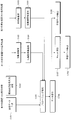
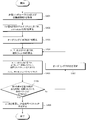
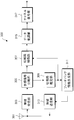
- FIG. 1 is a flowchart for explaining an overview of signal processing of the entire system according to the first embodiment of the present invention.
- the base station apparatus 100 generates transmission data (step S101), and transmits a known reference signal sequence to the connected first terminal apparatus 300 and second terminal apparatus 300 (step S101). S102).
- each terminal apparatus 300 performs propagation path estimation based on the received known reference signal sequence (step S103).
- Each terminal apparatus 300 notifies the estimated propagation path information to the base station apparatus 100.
- the notification method is not limited to a specific method, and the base station apparatus 100 can grasp the propagation path information. Any method may be used (step S104). For example, information obtained by quantizing the estimated propagation path information into a finite bit length may be notified. Further, a code book in which a plurality of linear filters are described in advance may be shared between the base station apparatus 100 and the terminal apparatus 300, and the index of the linear filter having the highest correlation with the propagation path information may be notified.
- Base station apparatus 100 acquires propagation path information from each terminal apparatus 300, and performs transmission encoding (precoding) described later on transmission data addressed to each terminal apparatus 300 based on the information (step S105). ).
- the precoded data is spatially multiplexed on the same radio resource and transmitted to a plurality of connected terminal devices 300 (step S106).
- the terminal device 300 that has received the signal in which the data addressed to the plurality of terminal devices 300 is spatially multiplexed detects the desired data of its own station based on the above-described propagation path information and the like (step S108). In 300, it is necessary to perform nonlinear arithmetic processing including modulo arithmetic (step S107), but in the second terminal apparatus 300, modulo arithmetic is not necessary.
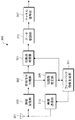
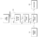
- FIG. 2 is a block diagram showing a configuration of base station apparatus 100 according to the first embodiment of the present invention.
- the base station apparatus 100 includes a channel encoding unit 101, a data modulation unit 103, a reference signal multiplexing unit 105, a precoding unit (precoding unit) 401, a radio transmission unit 111, a radio The reception unit 113, the control information acquisition unit 115, the CSI acquisition unit (acquisition unit) 117, and the transmission antenna 109 are configured.
- the transmission data series addressed to each terminal device 300 is subjected to channel coding in channel coding section 101 and then data modulated to QPSK, 16QAM, etc. in data modulation section 103.
- An output from data modulation section 103 is input to reference signal multiplexing section 105, and a known reference signal sequence for performing channel estimation in each terminal apparatus 300 is multiplexed in reference signal multiplexing section 105.
- the reference signals addressed to the terminal devices 300 are multiplexed so as to be orthogonal to each other so that they can be separated in the received terminal device 300.
- the reference signal is ideally arranged in an arbitrary radio resource, and the terminal apparatus 300 ideally performs channel estimation using the known reference signal sequence.
- the output of the reference signal multiplexing unit 105 is input to the precoding unit 401. Note that the propagation path information notified from each terminal device 300 is also input from the CSI acquisition unit 117 to the precoding unit 401.
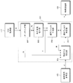
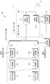
- FIG. 3 is a block diagram showing a device configuration of the precoding unit 401 according to the first embodiment of the present invention.
- the precoding unit 401 includes a linear filter generation unit 203, a lattice base reduction unit 501, a prior interference suppression unit 503, and a linear filter multiplication unit 207.
- the signal processing performed by the precoding unit 401 is almost the same as the signal processing performed by the precoding unit 401 shown in FIG. 17, but the signal processing performed by the lattice base reduction unit 501 and the prior interference suppression unit 503 is different. .
- signal processing performed in the lattice base reduction unit 501 will be described.
- the lattice base reduction unit 501 Based on the input channel matrix H, the lattice base reduction unit 501 calculates a unimodal matrix T that increases the orthogonality of H.
- the LLL algorithm is well known.
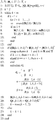
- FIG. 4 is a table showing the algorithm of the LLL algorithm. Based on the calculated T, signal processing in the prior interference suppression unit 503 and the linear filter generation unit 203 is performed.
- the constituent elements of the unimodular matrix T are preferably Gaussian integers, but numbers that belong to real numbers may be constituent elements if the deterioration of transmission characteristics can be tolerated.
- all the terminal devices 300 that are spatially multiplexed need to be the first terminal device 300 that can perform the modulo operation. Therefore, in the present embodiment, spatial multiplexing of the second terminal apparatus 300 is enabled by improving the conventional LLL algorithm.
- z ⁇ t, i 0 in the equation (6). Since z ⁇ t, i is the i-th component of the vector (T -1 z t ), it is expressed by the product of the i-th row of the matrix T -1 and z t .
- a row vector having the number of elements U in which the k-th component is 1 and all other components are 0 is defined as a k-th unit row vector e U, k .
- the nature of matrix when the k-th row of the matrix T U row U column is e U, i, the inverse matrix T -1 of the matrix T and matrix with e U, k to the i-th row become.
- the terminal device 300-i can perform transmission that does not require a modulo operation. That is, the i-th unit row vector e U, i only needs to be present in any row of the matrix T in order to realize transmission that does not require a modulo operation in the terminal device 300-i.
- the input value may be either the transposed matrix H T of the propagation path matrix H or the inverse matrix H ⁇ 1 . While the actual LLL algorithm outputs TH, the purpose of this embodiment is to make e U, i exist in any row of T. Therefore, any column vector of the matrix T H (T in FIG. 4) calculated by the LLL algorithm may be e U, i H.
- the LLL algorithm includes (1) quasi-orthogonalization processing from the 4th row to the 10th row, (2) condition comparison from the 11th row, and (3) from the 12th row to the 16th row. It consists of repetition of three processes of replacement work.
- the unimodular matrix T is directly calculated in the part of the quasi-orthogonalization process (1). Since the initial value of the unimodular matrix is the unit matrix I, e U and i H exist in the finally calculated T unless the quasi-orthogonalization process for the i-th column is performed. Note that the i-th column may be replaced with a different column (for example, the j-th column) by the condition comparison in (2) and the replacement operation in (3).
- the new j-th column becomes e U, i H.
- e U and i H exist in the v-th column when the algorithm is finished.
- FIG. 5 is a table showing an algorithm of the LLL algorithm according to the first embodiment of the present invention.
- the input is i indicating the terminal device number of the second terminal device 300 in addition to the propagation path matrix H, and the output is v indicating the column number where the unimodal matrix T and finally e U, i H are present. is there.
- the lattice base reduction unit 501 outputs two pieces of information, unimodular matrices T and v, according to the algorithm shown in FIG.
- the unimodular matrix T and the propagation path matrix H are input to the linear filter generation unit 203, and the linear filter W is generated.
- the generated linear filter is input to the prior interference suppression unit 503 and the linear filter multiplication unit 207.
- the prior interference suppression unit 503 receives the transmission signal vector d, the propagation path information H, the unimodular matrix T, v indicating the column number in which e U, i H exists, and the linear filter W, and the prior interference suppression unit 503 outputs X is output as follows.
- the calculation method of x realizes the equation (4).
- interference suppression for d ⁇ v is performed based on Expression (3-1), and other transmission symbols are performed based on Expression (3-3).
- Expression (3-1) When there are a plurality of second terminal devices 300, there are a plurality of numbers corresponding to v. In this case as well, all perturbation vectors corresponding to v may be set to zero.
- the x output from the prior interference suppression unit 503 is then input to the linear filter multiplication unit 207, multiplied by the linear filter W and the power normalization coefficient ⁇ , and the transmission signal vector s is output, which becomes the output of the precoding unit 401. .
- FIG. 6 is a flowchart showing signal processing in the precoding unit 401 according to the first embodiment of the present invention.
- the precoding unit 401 acquires the transmission symbol vector d and the propagation path information H (step S201).
- the lattice base reduction unit 501 calculates a unimodal matrix T that increases the orthogonality of H based on the input channel matrix H (step S202).
- the propagation path information H and T output from the lattice base reduction unit 501 are input to the linear filter generation unit 203, and a linear filter W is generated (step S203).
- the transmission symbol vector d input to the precoding unit 401 is input to the prior interference suppression unit 503, so that the interference component observed in each terminal device 300 is subtracted in advance (step S204).
- the process is performed for the first terminal apparatus 300 based on Expression (3-3), and for the second terminal apparatus 300 based on Expression (3-1).
- the linear filter multiplier 207 multiplies the input x by the linear filter W to calculate a transmission signal vector s (step S205).
- the output s of the precoding unit 401 is input to the radio transmission unit 111 of each corresponding transmission antenna 109.
- a baseband transmission signal is converted into a radio frequency (RF) transmission signal.
- the output signal of the wireless transmission unit 111 is transmitted from each transmission antenna 109.
- FIG. 7 is a block diagram showing the configuration of the first terminal apparatus 300 according to the first embodiment of the present invention.
- FIG. 8 is a block diagram showing a configuration of the second terminal apparatus 300 according to the first embodiment of the present invention.
- the terminal device 300 includes an antenna 301, a wireless reception unit 303, a reference signal separation unit 305, a propagation path estimation unit 309, a feedback information generation unit 311, and a wireless transmission unit 313.
- a propagation path compensation unit 601, a data demodulation unit 315, and a channel decoding unit 317 are configured.
- the terminal device 300-i is included in the second terminal device 300, and the remaining terminal devices 300 are all included in the first terminal device 300.
- the device configurations of the first terminal device 300 and the second terminal device 300 are the same, but the signal processing performed in each propagation path compensation unit 601 is different.
- each terminal device 300 a signal received by the antenna 301 is input to the wireless reception unit 303, and the wireless reception unit 303 converts the signal into a baseband signal.
- the signal converted into the baseband is input to the reference signal separation unit 305.
- reference signal separation section 305 the received signal is separated into a data series and a known reference signal series, the data series is input to propagation path compensation section 601, and the known reference signal series is input to propagation path estimation section 309.
- the propagation path estimation unit 309 performs propagation path estimation using the input known reference signal sequence. Since the known reference signal sequences addressed to each terminal apparatus 300 are transmitted from the base station apparatus 100 so as to be orthogonal to each other, the terminal apparatus 300 can estimate the propagation path information.
- the propagation path information estimated in the terminal apparatus 300-u corresponds to the u-th row component of the propagation path matrix H used in the precoding unit 401 of the base station apparatus 100.
- the estimated propagation path information is input to the propagation path compensation unit 601 and the feedback information generation unit 311, respectively.
- the feedback information generation unit 311 generates information to be fed back to the base station apparatus 100 according to the propagation path information format fed back by each terminal apparatus 300.
- the propagation path information format is not limited to anything. For example, information obtained by quantizing the estimated propagation path information into a finite bit length may be notified. Further, a code book in which a plurality of linear filters are described in advance may be shared between the base station apparatus 100 and the terminal apparatus 300, and the index of the linear filter having the highest correlation with the propagation path information may be notified.
- Information generated by feedback information generation section 311 is input to radio transmission section 313 and notified to base station apparatus 100.
- CSI acquisition section 117 acquires propagation path information H based on the notified information and its propagation path information format, and the acquired propagation path information is input to precoding section 401. become.
- the received data series is input to the propagation path compensation unit 601 to perform propagation path compensation.
- the received signal converted into the baseband band has the same format as that given by equation (6).
- the propagation path compensation unit 601 of the terminal device 300-u divides the power normalization term ⁇ from the input received signal. Therefore, although the terminal device 300 needs to grasp the value of ⁇ , ⁇ can be estimated from a known reference signal transmitted from the base station device 100. For example, ⁇ can be estimated by performing a precoding process similar to the received data sequence on a part of the known reference signal transmitted by the base station apparatus 100 for estimating the propagation path information. In the following, it is assumed that ⁇ can be estimated ideally. Note that, when the feedback accuracy of the propagation path information from the terminal apparatus 300 to the base station apparatus 100 is low, or when the time and frequency selectivity of the propagation path is severe, the desired signal d u in the received signal of the terminal apparatus 300- u.
- the amplitude and phase of fluctuate Since fluctuations in the amplitude and phase can be estimated in the same manner as the power normalization term ⁇ , compensation for fluctuations in the amplitude and phase may be performed simultaneously when dividing ⁇ . After the power normalization term is divided, a modulo operation having the same modulo width as the modulo operation used in the precoding unit 401 of the base station apparatus 100 is applied. However, the component corresponding to the terminal device 300-i among z ⁇ t , that is, z ⁇ , depending on the unimodulator matrix T calculated by the precoding unit 401 of the base station apparatus 100 of the present embodiment and the modulo calculation application method. t and i are 0.
- the propagation path compensation unit 701 of the terminal device 300-i included in the second terminal device 300 does not require a modulo operation, and only the power normalization coefficient ⁇ is divided.
- the modulo calculation is performed after the division of the power normalization coefficient ⁇ , as in the basic technique.
- the outputs of the propagation path compensation units 601 and 701 are input to the data demodulation unit 315 and the channel decoding unit 317, and after data demodulation and channel decoding are applied, transmission data of each terminal apparatus 300 is detected.
- the first terminal apparatus 300 and the second terminal apparatus 300 can be spatially multiplexed with high efficiency even in LRA-THP MU-MIMO.
- the first terminal apparatus 300 and the second terminal apparatus 300 are spatially multiplexed.
- the terminal apparatus 300 that performs the modulo operation and the terminal apparatus 300 that does not perform the modulo operation. Can be spatially multiplexed. Since the modulo operation suppresses an increase in transmission power accompanying an increase in IUI, it can contribute to an improvement in transmission characteristics. However, when the IUI is small, the transmission characteristics may be deteriorated due to modulo loss or precoding loss caused by the modulo operation, compared with the case where the modulo operation is not performed, and is particularly easily deteriorated during QPSK modulation.
- the spatially multiplexed terminal devices 300 are the first terminal devices 300, there may be a case where a transmission method is adopted that adaptively switches whether or not to apply a modulo operation according to the situation of the IUI. is there.
- a terminal with a small IUI observed is regarded as the second terminal apparatus 300, so that a QPSK modulated signal not subjected to modulo operation and a QPSK modulated signal subjected to modulo operation are spatially multiplexed by the method of the present embodiment. It becomes possible to make it.
- the modulo calculation To switch the modulo calculation, measure the power of the interference component that can be measured during actual precoding (for example, the second term in equation (3-1)), perform the modulo calculation if it exceeds a certain threshold, and if not exceed the modulo calculation Control may be performed so that it is not performed.
- the threshold value may be determined by performing BER measurement or the like in advance based on a given coding rate or the like.
- the terminal device 300 needs to know whether or not a modulo calculation is performed on the received signal.
- the base station apparatus 100 may newly notify the terminal apparatus 300 with a control signal, a method of notifying in association with the MCS shared by the base station apparatus 100 and the terminal apparatus 300 is conceivable. For example, in the case of QPSK modulation, control may be performed so that modulo operation is always performed, or a system in which QPSK performing modulo operation and QPSK not performing modulo operation are included in the MCS items, respectively.
- the present invention can be applied to an orthogonal frequency division multiple access (OFDMA) system that is employed in LTE downlink transmission.
- OFDMA orthogonal frequency division multiple access
- the present embodiment may be applied to each subcarrier, and the present embodiment may be applied to each resource block in which a plurality of subcarriers are grouped.
- SC-FDMA single carrier frequency division multiple access
- the first embodiment in a wireless communication system in which the first terminal device 300 and the second terminal device 300 are mixed, highly efficient spatial multiplexing by LRA-THP is possible. It can contribute to the improvement of the overall frequency utilization efficiency.
- the unimodular matrix T calculated by the lattice base reduction unit 501 and the signal processing in the prior interference suppression unit 503 are different from those in the prior art, so that the first terminal apparatus 300 and the second Clarified a method of spatially multiplexing the terminal device 300 of the above with LRA-THP.
- the convergence speed of the LLL algorithm may be significantly degraded as compared with the conventional method. Therefore, in the second embodiment, the first terminal apparatus 300 and the second terminal apparatus 300 are spatially multiplexed by LRA-THP by pre-ordering the propagation path matrix input to the lattice basis reduction unit 501. Thus, a method for avoiding a decrease in convergence of the LLL algorithm is targeted.
- a base station apparatus 100 (also referred to as a transmission apparatus) having N t transmission antennas 109 is connected to a terminal apparatus 300 (also referred to as a reception apparatus) having one antenna 301.
- the terminal device 300-i is the second terminal device 300 among the terminal devices 300 for the individually connected communication.
- the number of antennas 301 included in each terminal device 300 and the ratio of the first terminal device 300 and the second terminal device 300 included in the terminal device 300 are not limited to this, and a plurality of antennas 301 are provided.
- the present invention is also applicable when the terminal device 300 exists or when there are a plurality of second terminal devices 300.
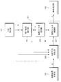
- FIG. 9 is a block diagram showing the configuration of the precoding unit 801 according to the second embodiment of the present invention.
- the precoding unit 801 includes a linear filter generation unit 203, a lattice base reduction unit 803, a prior interference suppression unit 805, and an ordering unit 807 in addition to the linear filter multiplication unit 207.
- the input channel matrix H is first input to the ordering unit 807 and subjected to the ordering process.
- the ordering means that the columns (or rows) of the matrix are exchanged.
- the channel information corresponding to the second terminal device 300 is controlled to be at the top of ordering pre channel matrix H p.
- the terminal apparatus 300-i is the second terminal apparatus 300 as the target of the present embodiment
- a matrix in which e U, i is arranged in the first row is used as the permutation matrix ⁇ .
- the other rows of ⁇ can be exchanged freely, so the permutation matrix is (U-1) in all! Street options will be considered.
- the column vectors of the input matrix are arranged in ascending order from the left in terms of improving the convergence characteristics of the algorithm.
- a certain permutation matrix ⁇ is generated by first performing QR decomposition with sorting such that the size of the column vector is ascending from the left with respect to the propagation path matrix H. To do. After that, the row having e U, i among the row components of the ridge may be rearranged at the top.
- the channel matrix H p that has been ordered and the selected ordering matrix ⁇ are output.
- the output H p of the ordering unit 807 is input to the lattice basis reduction unit 803 and subjected to lattice basis reduction processing.
- FIG. 10 is a table showing an algorithm used in the lattice basis reduction unit 803 according to the second embodiment of the present invention.
- the difference between FIG. 10 and FIG. 5 targeted in the first embodiment is a propagation path matrix component related to the second terminal device 300 (in this embodiment, the second terminal device 300 is the terminal device 300-i).
- the second terminal device 300 is the terminal device 300-i.
- quasi-orthogonalization processing is not performed for the i-th column component, (2) condition comparison and (3) replacement work are applied. With this processing, since the lattice base reduction can be performed in consideration of the terminal device 300-i, good transmission characteristics can be realized even if the second terminal devices 300 are mixed.
- the LLL algorithm is based on the premise that the signal processing of (1) to (3) is performed on all the components of the matrix, the method of FIG. 5 particularly includes a plurality of second terminal devices 300. In some cases, it takes an enormous amount of time for the algorithm to converge.
- the algorithm used in the second embodiment starts signal processing for an input matrix from a predetermined column number v, and a column vector having a column number smaller than v. Is not subjected to any signal processing.
- the propagation path matrix component related to the second terminal apparatus 300 is replaced with the first row (referred to as the first column in the algorithm because H H is input to the algorithm) by prior ordering. This is because.
- the convergence of the algorithm can be made almost equivalent to that of the conventional LLL algorithm shown in FIG.
- the number of second terminal devices 300 is one, 3 is input as v. That is, v is obtained by adding the number of second terminal apparatuses 300 to 2 which is the initial value of k in the conventional LLL algorithm.
- the lattice base reduction unit 803 finally outputs a unimodal matrix T.
- the linear filter generator 203 based on the ordering unit 807 outputs H p and lattice reduction unit 803 outputs T, the linear filter W is generated.
- the output W of the linear filter generation unit 203 is input to the prior interference suppression unit 805.
- the pre-interference suppression unit 805 receives the output of the ordering unit 807, the output T of the lattice base reduction unit 803, the ordered channel matrix H p and the transmission symbol vector d, and performs pre-interference suppression.
- Actual signal processing is almost the same as that of the first embodiment, and a transmission signal vector x as shown in Expression (4) is generated, but processing is slightly different.
- interference suppression is performed by using Td obtained by multiplying d by T as a new transmission symbol vector d ⁇ .
- Interference suppression is performed as a vector.
- the presence / absence of the modulo operation is determined according to the position of the unit row vector of the unimodular matrix, whereas in the second embodiment, out of d ⁇ Control is performed so that the modulo operation is not performed from the first component to the number of components of the second terminal device 300.
- the number of the second terminal devices 300 is 1, so that modulo operation is not performed only on d ⁇ 1 out of d ⁇ , that is, interference is performed based on Expression (3-1). It will be suppressed. If the number of second terminal apparatuses 300 is m, the modulo operation is not performed on d ⁇ 1 to d ⁇ m . For other transmission symbols, interference suppression is performed based on Equation (3-3). Through the above processing, the transmission code vector x finally output from the prior interference suppression unit 805 is given by Expression (8).
- the output x of the prior interference suppression unit 805 is input to the linear filter multiplication unit 207 and multiplied by the linear filter W.
- FIG. 11 is a flowchart showing signal processing of the precoding unit 801 according to the second embodiment of the present invention.
- the precoding unit 801 acquires the transmission symbol vector d and the propagation path information H (step S301).
- the input channel matrix H is first input to the ordering unit 807 and subjected to the ordering process (step S302).
- the lattice base reduction unit 803 calculates a unimodal matrix T that increases the orthogonality of H p based on the input channel matrix H p and the algorithm shown in FIG. 10 (step S303).
- the propagation path information H p and T output from the lattice base reduction unit 501 are input to the linear filter generation unit 203, and a linear filter W is generated (step S304).
- the transmission symbol vector d input to the precoding unit 801 is input to the prior interference suppression unit 805, so that the interference component observed in each terminal device 300 is subtracted in advance (step S305).
- the process is performed for the first terminal apparatus 300 based on Expression (3-3), and for the second terminal apparatus 300 based on Expression (3-1).
- the linear filter multiplier 207 multiplies the input x by the linear filter W to calculate a transmission signal vector s (step S306).
- the subsequent signal processing is the same as in FIG. 2 including the signal processing of the base station apparatus 100 for the output of the precoding unit 801, and thus the description thereof is omitted.
- terminal device 300 The configuration of the terminal device 300 according to the second embodiment is the same as that of FIG. 7 and FIG. 8 for both the first terminal device 300 and the second terminal device 300, and the signal processing performed is also the same. Omitted.
- the lattice basis reduction algorithm is compared with the method of the first embodiment, particularly when the number of second terminal devices 300 is large. It is possible to converge at high speed.
- the unimodular matrix T calculated by the lattice base reduction unit 803 is different from the T used in the conventional LRA-THP, so that The second terminal apparatus 300 can be spatially multiplexed.
- limiting the generation of T may significantly reduce the orthogonality of the propagation paths and the convergence speed of the lattice reduction algorithm.
- LRA-THP can be regarded as a combination of two signal processings, quasi-orthogonalization processing for a propagation path and pre-interference suppression processing by THP, and the conventional methods mainly use quasi-orthogonalization processing.
- the third embodiment is directed to a method for realizing spatial multiplexing by changing the THP prior interference suppression processing.
- a base station apparatus 100 (also referred to as a transmission apparatus) having N t transmission antennas 109 is connected to a terminal apparatus 300 (also referred to as a reception apparatus) having one antenna 301.
- the terminal device 300-i is the second terminal device 300 among the terminal devices 300 for the individually connected communication.
- the number of antennas 301 included in each terminal device 300 and the ratio of the first terminal device 300 and the second terminal device 300 included in the terminal device 300 are not limited to this, and a plurality of antennas 301 are provided.
- the present invention is also applicable when the terminal device 300 exists or when there are a plurality of second terminal devices 300.
- Base station apparatus 100 The configuration of the base station apparatus 100 according to the third embodiment is almost the same as that in FIG. 2, and only the signal processing in the precoding unit 801 is different. Therefore, the precoding unit according to the third embodiment will be described below. .
- FIG. 12 is a block diagram showing a configuration of the precoding unit 901 according to the third embodiment of the present invention.
- the apparatus configuration is almost the same as that in FIG. 9, the position of the ordering unit 903 is different from that of the second embodiment, and a perturbation vector control unit 905 is added.
- the input propagation path matrix H is input to the lattice basis reduction unit 907 and subjected to lattice basis reduction processing.
- the unimolecular matrix T calculated by the lattice base reduction unit 907 is limited. However, in the present embodiment, anything calculated as long as the calculated T is a unimodal matrix. good.
- the LLL algorithm in FIG. 4 may be applied as it is to calculate the unimolecular matrix T.
- the calculated matrix T is then input to the linear filter generation unit 909 and the prior interference suppression unit 911.
- the lattice filter reduction unit 907 output T, the propagation path matrix H, and the ordering unit 903 output ⁇ are input to the linear filter generation unit 909.
- the signal processing in the ordering unit 903 will be described later.
- the unit matrix I is input as ⁇ .
- the order of multiplication of the unimodal matrix T and the permutation matrix ⁇ is different from that of the second embodiment.
- the linear filter generation unit 909 output W is input to the prior interference suppression unit 911.
- the pre-interference suppression unit 911 receives the propagation path matrix H, the output of the ordering unit 903, the output T of the lattice basis reduction unit 907, and the transmission symbol vector d, and performs pre-interference suppression.
- the perturbation vector z t is the size of the residual IUI determined according to the channel matrix (a i, j (i> j)), the perturbation vector value changes when the propagation path matrix changes.
- the prior interference suppression unit 911 output x is once input to the perturbation vector control unit 905 and whether the perturbation term T -1 ⁇ -1 z t of the modulo operation observed by the second terminal device 300 is 0 or not. If the perturbation term T -1 ⁇ -1 z t is not 0, the input x is input to the linear filter multiplication unit 207. And outputs a control signal to the ordering unit 903 so as to generate a new permutation matrix.
- the selectable permutation matrix is U! Since only one exists, T ⁇ 1 ⁇ ⁇ 1 z t is calculated for all of them, and a permutation matrix in which the component related to the second terminal apparatus 300 is 0 may be found.
- the transmission code vector x is input to the linear filter multiplication unit 207.
- the linear filter multiplication unit 207 performs power normalization and generates a precoding unit 901 output s.
- FIG. 13 is a flowchart showing signal processing of the precoding unit 901 according to the third embodiment of the present invention.
- the precoding unit 901 acquires the transmission symbol vector d and the propagation path information H (step S401).
- the lattice base reduction unit 907 calculates a unimodal matrix T that increases the orthogonality of H based on the input propagation path matrix H and the algorithm shown in FIG. 4 (step S402).
- the uniting matrix I is input as the ordering matrix ⁇ by the ordering unit 903 (step S403).
- the propagation path information H, T output from the lattice basis reduction unit 907, and the ordering matrix ⁇ are input to the linear filter generation unit 909, and the linear filter W is generated (step S404).
- the transmission symbol vector d input to the precoding unit 901 is input to the prior interference suppression unit 911, so that the interference component observed in each terminal device 300 is subtracted in advance (step S405). At this time, it is always performed based on the equation (3-3).
- the perturbation vector control unit 905 determines whether or not the perturbation vector observed by the second terminal apparatus 300 is 0 (step S406). If it is not 0 (step S406: No), the perturbation vector control unit 905 determines the ordering unit 903. Then, a control signal is output so as to update the ordering matrix ⁇ (step S407), and the process returns to step S404. If it is 0 (step S406: Yes), the linear filter multiplier 207 multiplies the input x by the linear filter W to calculate a transmission signal vector s (step S408).
- the transmission characteristic of the second terminal apparatus 300 is proportional to the size of the remaining perturbation vector. to degrade.
- the modulation method is phase modulation such as QPSK
- the assigned perturbation vector exists in the same quadrant as the transmission data (for example, the transmission signal addressed to the second terminal apparatus 300 is 2 at the time of QPSK modulation).
- the perturbation vector can be expressed as p + jq using a positive integer (p, q), and does not affect data demodulation, and thus becomes a perturbation vector.
- a permutation matrix may be selected. The same thing can be used that even when 16QAM is used, the addition of the perturbation vector may not affect the signal demodulation depending on the position of the signal candidate point.
- the configuration of the terminal device 300 according to the third embodiment is the same as that of FIGS. 7 and 8 for both the first terminal device 300 and the second terminal device 300, and the signal processing performed is the first and second. Since it is the same as what was demonstrated in embodiment, description is abbreviate
- the first terminal device 300 and the second terminal device are changed by changing the signal processing in the prior interference suppression unit 911 without changing the lattice basis reduction algorithm performed in the lattice basis reduction unit 907. The method of spatial multiplexing with 300 was targeted.
- the prior interference suppression method since the prior interference suppression method is changed, there is a problem that the transmission quality is not constant between the spatially multiplexed terminal apparatuses 300, but the lattice base reduction is performed completely. Therefore, it is easy to maintain the orthogonality of the propagation paths, and spatial multiplexing can be performed without affecting the convergence speed of the convergence algorithm.
- the fourth embodiment is directed to a method in which the first terminal apparatus 300 and the second terminal apparatus 300 are spatially multiplexed by nonlinear MU-MIMO using lattice basis reduction by applying the concept of VP.
- a base station apparatus 100 (also referred to as a transmission apparatus) having N t transmission antennas 109 is connected to a terminal apparatus 300 (also referred to as a reception apparatus) having one antenna 301.
- the terminal device 300-i is the second terminal device 300 among the terminal devices 300 for the individually connected communication.
- the number of antennas 301 included in each terminal device 300 and the ratio of the first terminal device 300 and the second terminal device 300 included in the terminal device 300 are not limited to this, and a plurality of antennas 301 are provided.
- the present invention is also applicable when the terminal device 300 exists or when there are a plurality of second terminal devices 300.
- THP MU-MIMO reduces transmission power by adding a perturbation vector to a linear MU-MIMO transmission signal.
- THP since the perturbation vector is obtained independently by each terminal device 300 based on Expression (3-2), the required transmission power of each terminal device 300 can be made constant.
- VP is a method for obtaining a perturbation vector that minimizes the transmission power of a transmission signal itself that is spatially multiplexed and transmitted, and the transmission signal can be expressed as in Expression (11-2).
- this is the same as the equation (11-1), but the perturbation vector is multiplied by T- 1 .
- precoding for spatially multiplexing the first terminal apparatus 300 and the second terminal apparatus 300 is performed.
- FIG. 14 is a block diagram showing a configuration of a precoding unit 1001 according to the fourth embodiment of the present invention.
- the precoding unit 1001 includes a linear filter generation unit 1003, a lattice basis reduction unit 1005, and a perturbation vector control unit 1007.
- the propagation path matrix H is input to the lattice basis reduction unit 1005, and lattice basis reduction is performed.
- the unimodular matrix T may be obtained based on the LLL algorithm shown in FIG.
- the matrix T output from the lattice base reduction unit 1005 is input to the linear filter generation unit 1003.
- the linear filter generation unit 1003 receives the output T of the lattice base reduction unit 1005 and the propagation path matrix H, and generates a linear filter.
- G TH
- G a diagonal matrix.
- an inverse matrix G ⁇ 1 of G may be used.
- a linear filter based on the MMSE standard may be used.
- the generated linear filter W is input to the perturbation vector control unit 1007.
- the perturbation vector control unit 1007 receives the transmission symbol vector d, the linear filter W, and the unimodular matrix T, and calculates a perturbation vector.
- a perturbation vector that does not require a modulo operation is searched for as a perturbation vector in the terminal device 300-i belonging to the second terminal device 300.
- the transmission signal when the prior interference suppression by THP is not performed can also be expressed as in Expression (11-3).
- the transmission code x i of the terminal device 300-i addressed belonging to the second terminal device 300, z ⁇ t, will be i is applied, this remains will not perform modulo arithmetic in the terminal device 300-i
- the signal cannot be demodulated. Therefore, the perturbation vector control unit 1007, in addition to the z ⁇ t, imparting a new perturbation vector z T.
- z T is referred to as a second perturbation vector. That is, it means that the final transmission signal is expressed by the equation (11-4).
- the terminal device 300-i can perform signal demodulation without using a modulo operation.
- the perturbation vectors other than zT , i but unless an appropriate perturbation vector is selected, the transmission characteristics will be greatly degraded. In order not to deteriorate the transmission characteristics, it is necessary to select perturbation vectors other than z T, i so as to minimize the transmission signal power. In other words, the perturbation vector z T to be obtained becomes to satisfy the equation (12).
- FIG. 15 is a flowchart showing signal processing of the precoding unit 1001 according to the fourth embodiment of the present invention.
- the precoding unit 1001 acquires the transmission symbol vector d and the propagation path information H (step S501).
- the lattice basis reduction unit 1005 calculates a unimodal matrix T that increases the orthogonality of H based on the input propagation path matrix H and the algorithm shown in FIG. 4 (step S502).
- the propagation path information H and T output from the lattice base reduction unit 1005 are input to the linear filter generation unit 1003, and a linear filter W is generated (step S503).
- the perturbation vector control unit 1007 generates a first perturbation vector (step S504).
- the perturbation vector control unit 1007 generates a second perturbation vector based on the propagation path information H, T output from the lattice base reduction unit 1005, and the linear filter W (step S505).
- the perturbation vector control unit 1007 adds the first and second perturbation vectors to d to generate a transmission code vector x (step S506). Further, the perturbation vector control unit 1007 multiplies the transmission code vector x by the linear filter W to generate a transmission signal vector s (step S507).
- the subsequent signal processing of the base station apparatus 100 is the same as in FIG.
- the configuration of the terminal device 300 according to the fourth embodiment is the same as that of FIGS. 7 and 8 for both the first terminal device 300 and the second terminal device 300, and the signal processing performed is also from the first to the third. Since it is the same as embodiment, description is abbreviate
- the fourth embodiment is directed to a method of spatially multiplexing the first terminal apparatus 300 and the second terminal apparatus 300 by appropriately controlling the perturbation vector in nonlinear MU-MIMO transmission based on lattice basis reduction. It was. Since the perturbation vector is not calculated for each terminal device 300 as targeted in the first to third embodiments, the amount of computation increases significantly, but the second terminal device 300 is spatially multiplexed. It is possible to minimize the deterioration of the transmission characteristics that occur.
- the embodiment of the present invention has been described in detail with reference to the drawings. However, the specific configuration is not limited to this embodiment, and the design and the like within the scope of the present invention are also within the scope of the claims. include.
- the program that operates in the terminal device 300 and the base station device 100 related to the present invention is a program (a program that causes a computer to function) that controls the CPU and the like so as to realize the functions of the above-described embodiments related to the present invention. Information handled by these devices is temporarily stored in the RAM at the time of processing, then stored in various ROMs and HDDs, read out by the CPU, and corrected and written as necessary.
- a semiconductor medium for example, ROM, nonvolatile memory card, etc.
- an optical recording medium for example, DVD, MO, MD, CD, BD, etc.
- a magnetic recording medium for example, magnetic tape, Any of a flexible disk etc.
- the program when distributing to the market, the program can be stored and distributed on a portable recording medium, or transferred to a server computer connected via a network such as the Internet.
- the storage device of the server computer is also included in the present invention.
- part or all of the terminal device 300 and the base station device 100 in the above-described embodiment may be realized as an LSI that is typically an integrated circuit.
- Each functional block of the terminal apparatus 300 and the base station apparatus 100 may be individually made into a processor, or a part or all of them may be integrated into a processor.
- the method of circuit integration is not limited to LSI, and may be realized by a dedicated circuit or a general-purpose processor.
- an integrated circuit based on the technology can also be used.
- the embodiment of the present invention has been described in detail with reference to the drawings. However, the specific configuration is not limited to this embodiment, and the design and the like within the scope not departing from the gist of the present invention are also claimed. Included in the range.
- the present invention is applicable to a wireless communication device.
- DESCRIPTION OF SYMBOLS 100 Base station apparatus 101 Channel encoding part 103 Data modulation part 105 Reference signal multiplexing part 107 Precoding part 109 Transmission antenna 111 Wireless transmission part 113 Wireless reception part 115 Control information acquisition part 117 CSI acquisition part 201 Lattice base reduction part 203 Linear filter generation Unit 205 prior interference suppression unit 207 linear filter multiplication unit 300 terminal device 301 antenna 303 wireless reception unit 305 reference signal separation unit 307 propagation path compensation unit 309 propagation path estimation unit 311 feedback information generation unit 313 wireless transmission unit 315 data demodulation unit 317 channel Decoding unit 401 Precoding unit 501 Lattice base reduction unit 503 Pre-interference suppression unit 601 Propagation channel compensation unit 701 Propagation channel compensation unit 801 Precoding unit 803 Lattice base reduction unit 805 Pre-interference suppression unit 807 Orderly Grayed section 901 Precoding section 903 ordering unit 905 perturbation vector controller 907 lattice reduction unit 909 linear filter generating unit 911 in advance interference suppression unit 100
Abstract
Selon l'invention, un premier terminal dans lequel des calculs modulo peuvent être effectués et un second terminal dans lequel des calculs modulo ne peuvent pas être effectués sont spatialement multiplexés même en MU-MIMO non linéaire reposant sur LRA-THP. Cette station de base, qui est équipée d'une pluralité d'antennes de transmission, et communique sans fil avec une pluralité de terminaux comprenant au moins une antenne, comporte : une unité d'acquisition qui acquiert une première matrice de canal représentant des informations de canal, sur la base de premières informations de commande associées à des informations de canal entre les terminaux ; et une unité de précodage qui précode chaque élément de données de transmission destinées aux terminaux, sur la base de la première matrice de canal et d'une seconde matrice de canal obtenue par multiplication de la première matrice de canal par une matrice de transformation. Après précodage, une pluralité de données de transmission sont spatialement multiplexées et transmises à la même ressource sans fil.
Applications Claiming Priority (2)
| Application Number | Priority Date | Filing Date | Title |
|---|---|---|---|
| JP2011108678A JP2012244189A (ja) | 2011-05-13 | 2011-05-13 | 基地局装置、移動局装置、制御プログラムおよび集積回路 |
| JP2011-108678 | 2011-05-13 |
Publications (1)
| Publication Number | Publication Date |
|---|---|
| WO2012157393A1 true WO2012157393A1 (fr) | 2012-11-22 |
Family
ID=47176733
Family Applications (1)
| Application Number | Title | Priority Date | Filing Date |
|---|---|---|---|
| PCT/JP2012/060435 WO2012157393A1 (fr) | 2011-05-13 | 2012-04-18 | Station de base, station mobile, programme de commande et circuit intégré |
Country Status (2)
| Country | Link |
|---|---|
| JP (1) | JP2012244189A (fr) |
| WO (1) | WO2012157393A1 (fr) |
Cited By (3)
| Publication number | Priority date | Publication date | Assignee | Title |
|---|---|---|---|---|
| WO2014122850A1 (fr) * | 2013-02-06 | 2014-08-14 | シャープ株式会社 | Dispositif station de base, procédé de précodage, circuit intégré et système de radiocommunication |
| WO2016095171A1 (fr) * | 2014-12-18 | 2016-06-23 | 华为技术有限公司 | Procédé, dispositif, et système de pré-codage |
| JP6159839B1 (ja) * | 2016-03-08 | 2017-07-05 | ソフトバンク株式会社 | 基地局装置 |
Families Citing this family (2)
| Publication number | Priority date | Publication date | Assignee | Title |
|---|---|---|---|---|
| CN108667552A (zh) * | 2017-03-28 | 2018-10-16 | 中兴通讯股份有限公司 | 一种预编码处理方法及装置 |
| JP7223676B2 (ja) * | 2019-11-15 | 2023-02-16 | Kddi株式会社 | 無線通信の物理レイヤにおけるセキュリティを考慮した通信装置、通信方法、及びプログラム |
Citations (1)
| Publication number | Priority date | Publication date | Assignee | Title |
|---|---|---|---|---|
| JP2009507400A (ja) * | 2006-06-01 | 2009-02-19 | 株式会社東芝 | 無線通信装置 |
-
2011
- 2011-05-13 JP JP2011108678A patent/JP2012244189A/ja not_active Withdrawn
-
2012
- 2012-04-18 WO PCT/JP2012/060435 patent/WO2012157393A1/fr active Application Filing
Patent Citations (1)
| Publication number | Priority date | Publication date | Assignee | Title |
|---|---|---|---|---|
| JP2009507400A (ja) * | 2006-06-01 | 2009-02-19 | 株式会社東芝 | 無線通信装置 |
Non-Patent Citations (4)
| Title |
|---|
| HIROSHI NAKANO ET AL.: "Adaptive THP Scheme Control for Downlink MU-MIMO Systems", IEICE TECHNICAL REPORT, RCS2009-293, 24 February 2010 (2010-02-24), pages 203 - 208 * |
| HIROSHI NAKANO ET AL.: "Joint Quasi-orthogonalization for Nonlinear Precoding MU-MIMO", IEICE TECHNICAL REPORT, RCS2010-183, 9 December 2010 (2010-12-09), pages 145 - 150 * |
| TAKESHI SAWADA ET AL.: "A Consideration on THP-OFDM with No Modulo Arthmetic Device", IEICE TECHNICAL REPORT, CS2009-71, 21 January 2010 (2010-01-21), pages 25 - 30 * |
| TOMOYUKI YAMADA ET AL.: "Symbol-wise Precoding in Multiuser MIMO Downlink", IEICE TECHNICAL REPORT, RCS2010-205, 13 January 2011 (2011-01-13), pages 37 - 42 * |
Cited By (4)
| Publication number | Priority date | Publication date | Assignee | Title |
|---|---|---|---|---|
| WO2014122850A1 (fr) * | 2013-02-06 | 2014-08-14 | シャープ株式会社 | Dispositif station de base, procédé de précodage, circuit intégré et système de radiocommunication |
| WO2016095171A1 (fr) * | 2014-12-18 | 2016-06-23 | 华为技术有限公司 | Procédé, dispositif, et système de pré-codage |
| JP6159839B1 (ja) * | 2016-03-08 | 2017-07-05 | ソフトバンク株式会社 | 基地局装置 |
| JP2017163242A (ja) * | 2016-03-08 | 2017-09-14 | ソフトバンク株式会社 | 基地局装置 |
Also Published As
| Publication number | Publication date |
|---|---|
| JP2012244189A (ja) | 2012-12-10 |
Similar Documents
| Publication | Publication Date | Title |
|---|---|---|
| JP5804594B2 (ja) | プリコーディング装置、プリコーディング用プログラムおよび集積回路 | |
| US8711975B2 (en) | Tomlinson Harashima precoding with additional receiver processing in a multi-user multiple-input multiple-output wireless transmission system | |
| US9008166B2 (en) | Filter calculating device, transmitting device, receiving device, processor, and filter calculating method | |
| WO2012121153A1 (fr) | Système de communication sans fil, dispositif de station de base et dispositif terminal | |
| JP5908307B2 (ja) | プリコーディング装置、無線送信装置、無線受信装置、無線通信システムおよび集積回路 | |
| KR20160025487A (ko) | 신호 처리 장치, 신호 처리 방법 및 기록 매체 | |
| US8811215B2 (en) | Apparatus and method for detecting signal in spatial multiplexing system | |
| WO2012157393A1 (fr) | Station de base, station mobile, programme de commande et circuit intégré | |
| US8989296B2 (en) | Operating method of wireless local area network station | |
| JP5859913B2 (ja) | 無線受信装置、無線送信装置、無線通信システム、プログラムおよび集積回路 | |
| US9185577B2 (en) | Transmission apparatus, reception apparatus, wireless communication system, control program and integrated circuit | |
| WO2013018555A1 (fr) | Dispositif de réception sans fil et programme | |
| JP5641787B2 (ja) | 端末装置及びそれを用いた無線通信システム | |
| WO2014122850A1 (fr) | Dispositif station de base, procédé de précodage, circuit intégré et système de radiocommunication | |
| WO2012063538A1 (fr) | Dispositif de transmission sans fil, dispositif de réception sans fil, dispositif de communication sans fil et circuit intégré | |
| JP5909104B2 (ja) | 無線送信装置、無線受信装置、無線通信システムおよびプリコーディング方法 | |
| Simarro et al. | Block diagonalization aided precoding algorithm for large MU-MIMO systems | |
| JP5802942B2 (ja) | 無線通信システム、無線送信装置および無線通信方法 | |
| JP2013123196A (ja) | プリコーディング装置、無線送信装置、プリコーディング方法、プログラムおよび集積回路 | |
| JP5753041B2 (ja) | 無線送信装置、無線受信装置、および無線通信システム | |
| JP5676221B2 (ja) | 送信装置、通信システム、通信方法、プロセッサ | |
| JP2012070172A (ja) | 送信装置、受信装置、無線通信システム、制御プログラムおよび集積回路 | |
| Nishimori et al. | Block diagonalization with user antenna selection for multiuser MIMO systems |
Legal Events
| Date | Code | Title | Description |
|---|---|---|---|
| 121 | Ep: the epo has been informed by wipo that ep was designated in this application |
Ref document number: 12786237 Country of ref document: EP Kind code of ref document: A1 |
|
| NENP | Non-entry into the national phase |
Ref country code: DE |
|
| 122 | Ep: pct application non-entry in european phase |
Ref document number: 12786237 Country of ref document: EP Kind code of ref document: A1 |