WO2013129552A1 - 燃料電池システム - Google Patents
燃料電池システム Download PDFInfo
- Publication number
- WO2013129552A1 WO2013129552A1 PCT/JP2013/055347 JP2013055347W WO2013129552A1 WO 2013129552 A1 WO2013129552 A1 WO 2013129552A1 JP 2013055347 W JP2013055347 W JP 2013055347W WO 2013129552 A1 WO2013129552 A1 WO 2013129552A1
- Authority
- WO
- WIPO (PCT)
- Prior art keywords
- flow rate
- supply flow
- stack
- target
- compressor
- Prior art date
Links
Images


Classifications
-
- H—ELECTRICITY
- H01—ELECTRIC ELEMENTS
- H01M—PROCESSES OR MEANS, e.g. BATTERIES, FOR THE DIRECT CONVERSION OF CHEMICAL ENERGY INTO ELECTRICAL ENERGY
- H01M8/00—Fuel cells; Manufacture thereof
- H01M8/04—Auxiliary arrangements, e.g. for control of pressure or for circulation of fluids
- H01M8/04298—Processes for controlling fuel cells or fuel cell systems
- H01M8/04694—Processes for controlling fuel cells or fuel cell systems characterised by variables to be controlled
- H01M8/04746—Pressure; Flow
- H01M8/04753—Pressure; Flow of fuel cell reactants
-
- H—ELECTRICITY
- H01—ELECTRIC ELEMENTS
- H01M—PROCESSES OR MEANS, e.g. BATTERIES, FOR THE DIRECT CONVERSION OF CHEMICAL ENERGY INTO ELECTRICAL ENERGY
- H01M8/00—Fuel cells; Manufacture thereof
- H01M8/04—Auxiliary arrangements, e.g. for control of pressure or for circulation of fluids
- H01M8/04082—Arrangements for control of reactant parameters, e.g. pressure or concentration
- H01M8/04089—Arrangements for control of reactant parameters, e.g. pressure or concentration of gaseous reactants
- H01M8/04111—Arrangements for control of reactant parameters, e.g. pressure or concentration of gaseous reactants using a compressor turbine assembly
-
- H—ELECTRICITY
- H01—ELECTRIC ELEMENTS
- H01M—PROCESSES OR MEANS, e.g. BATTERIES, FOR THE DIRECT CONVERSION OF CHEMICAL ENERGY INTO ELECTRICAL ENERGY
- H01M8/00—Fuel cells; Manufacture thereof
- H01M8/04—Auxiliary arrangements, e.g. for control of pressure or for circulation of fluids
- H01M8/04298—Processes for controlling fuel cells or fuel cell systems
- H01M8/04313—Processes for controlling fuel cells or fuel cell systems characterised by the detection or assessment of variables; characterised by the detection or assessment of failure or abnormal function
- H01M8/0438—Pressure; Ambient pressure; Flow
- H01M8/04395—Pressure; Ambient pressure; Flow of cathode reactants at the inlet or inside the fuel cell
-
- Y—GENERAL TAGGING OF NEW TECHNOLOGICAL DEVELOPMENTS; GENERAL TAGGING OF CROSS-SECTIONAL TECHNOLOGIES SPANNING OVER SEVERAL SECTIONS OF THE IPC; TECHNICAL SUBJECTS COVERED BY FORMER USPC CROSS-REFERENCE ART COLLECTIONS [XRACs] AND DIGESTS
- Y02—TECHNOLOGIES OR APPLICATIONS FOR MITIGATION OR ADAPTATION AGAINST CLIMATE CHANGE
- Y02E—REDUCTION OF GREENHOUSE GAS [GHG] EMISSIONS, RELATED TO ENERGY GENERATION, TRANSMISSION OR DISTRIBUTION
- Y02E60/00—Enabling technologies; Technologies with a potential or indirect contribution to GHG emissions mitigation
- Y02E60/30—Hydrogen technology
- Y02E60/50—Fuel cells
Definitions
- the present invention relates to a fuel cell system.
- JP2009-123550A as a conventional fuel cell system, a portion of the cathode gas discharged from the cathode compressor that is unnecessary for power generation in the fuel cell stack is discharged to the cathode gas discharge passage through the bypass passage.
- the above-described conventional fuel cell system controls the opening degree of the bypass valve provided in the bypass passage based on the actual stack supply flow rate and the target stack supply flow rate so that the actual stack supply flow rate becomes the target stack supply flow rate.
- the actual stack supply flow rate cannot be made to match the target stack supply flow rate, especially when the opening resolution of the bypass valve is rough.
- the opening and closing of the valve may be repeated.
- the bypass valve is a stepping motor, there is a concern that abnormal noise is generated. Therefore, in order to prevent such opening and closing of the bypass valve, it is possible to fix the bypass valve when the actual stack supply flow rate is close to the target stack supply flow rate.
- bypass valve when the bypass valve is fixed when the actual stack supply flow rate is close to the target stack supply flow rate (when it falls within the bypass valve fixing range), for example, the target stack supply flow rate may increase and the bypass valve may be closed. Even if it becomes possible, the actual stack supply flow rate is controlled in the vicinity of the target stack supply flow rate, the bypass valve remains fixed, and excess cathode gas may be supplied by the cathode compressor. If it does so, there exists a concern that the power consumption of a cathode compressor increases and a fuel consumption deteriorates.
- the present invention has been made paying attention to such problems, and an object thereof is to provide a fuel cell system capable of suppressing the above-mentioned disadvantages.
- a certain aspect of the present invention is applied to a fuel cell system using a cathode gas bypass system using a compressor, and controls a compressor and a bypass valve as follows.
- the compressor control performs a stack for changing the actual stack supply flow rate to the target stack supply flow rate based on the detected actual stack supply flow rate and the target stack supply flow rate calculated based on the demand of the fuel cell stack. Calculate the required compressor supply flow rate. Then, the larger one of the stack required compressor supply flow rate and the lower limit flow rate determined according to the operation state of the fuel cell system is set as the target compressor supply flow rate, and the compressor is controlled so as to become the set target compressor supply flow rate. .
- the actual stack supply flow rate becomes the target stack supply flow rate based on the detected actual stack supply flow rate and the target stack supply flow rate calculated based on the demand of the fuel cell stack.
- the bypass valve is controlled.
- the actual stack supply flow rate falls within a predetermined bypass valve fixing range based on the target stack supply flow rate, and The bypass valve is fixed when the actual stack supply flow rate becomes smaller than the target stack supply flow rate. Then, after the bypass valve is fixed in this way, the fixation of the bypass valve is released when the target compressor supply flow rate becomes larger than the lower limit flow rate.
- FIG. 1 is a schematic diagram of a fuel cell system according to an embodiment of the present invention.
- FIG. 2 is a diagram showing the relationship between the dilution request compressor supply flow rate and the ultimate power generation request stack supply flow rate according to the load of the fuel cell stack.
- FIG. 3 shows a control block of the cathode system according to the present embodiment.
- FIG. 4 is a flowchart for explaining control contents performed by the controller at the bypass valve fixing release signal output unit.
- FIG. 5 is a flowchart for explaining the control contents performed by the controller at the bypass valve fixing signal output unit.
- FIG. 6 is a time chart for explaining the operation of controlling the cathode system according to the present embodiment.
- FIG. 7 shows a control block of a cathode system according to a comparative example.
- FIG. 8 is a time chart showing the operation of controlling the cathode system according to the comparative example.
- FIG. 9 is a time chart showing the operation when the operation of the bypass valve is prohibited when the actual stack supply flow rate falls below the target stack supply flow rate when the bypass valve is opened in the control of the cathode system according to the comparative example. It is.
- an electrolyte membrane is sandwiched between an anode electrode (fuel electrode) and a cathode electrode (oxidant electrode), an anode gas containing hydrogen in the anode electrode (fuel gas), and a cathode gas containing oxygen in the cathode electrode (oxidant) Electricity is generated by supplying gas.
- the electrode reaction that proceeds in both the anode electrode and the cathode electrode is as follows.
- Anode electrode 2H 2 ⁇ 4H + + 4e ⁇ (1)
- Cathode electrode 4H + + 4e ⁇ + O 2 ⁇ 2H 2 O (2)
- the fuel cell generates an electromotive force of about 1 volt by the electrode reactions (1) and (2).
- a fuel cell When a fuel cell is used as a power source for automobiles, it requires a large amount of power, so it is used as a fuel cell stack in which several hundred fuel cells are stacked. Then, a fuel cell system that supplies anode gas and cathode gas to the fuel cell stack is configured, and electric power for driving the vehicle is taken out.
- FIG. 1 is a schematic diagram of a fuel cell system 100 according to an embodiment of the present invention.
- the fuel cell system 100 includes a fuel cell stack 1, a cathode gas supply / discharge device 2, an anode gas supply / discharge device 3, and a controller 4.
- the fuel cell stack 1 is formed by stacking several hundred fuel cells, and receives the supply of anode gas and cathode gas to generate electric power necessary for driving the vehicle.
- the cathode gas supply / discharge device 2 supplies the cathode gas to the fuel cell stack 1 and discharges the cathode off-gas discharged from the fuel cell stack 1 to the outside air.
- the cathode gas supply / discharge device 2 includes a cathode gas supply passage 20, a filter 21, a cathode compressor 22, a cathode gas discharge passage 23, a cathode pressure regulating valve 24, a bypass passage 25, a bypass valve 26, and a first flow rate.
- the sensor 41, the 2nd flow sensor 42, the pressure sensor 43, and the temperature sensor 44 are provided.
- the cathode gas supply passage 20 is a passage through which the cathode gas supplied to the fuel cell stack 1 flows.
- the cathode gas supply passage 20 has one end connected to the filter 21 and the other end connected to the cathode gas inlet hole of the fuel cell stack 1.
- the filter 21 removes foreign matters in the cathode gas taken into the cathode gas supply passage 20.
- the cathode compressor 22 is provided in the cathode gas supply passage 20.
- the cathode compressor 22 takes air (outside air) as cathode gas into the cathode gas supply passage 20 via the filter 21 and supplies the air to the fuel cell stack 1.
- the cathode gas discharge passage 23 is a passage through which the cathode off gas discharged from the fuel cell stack 1 flows. One end of the cathode gas discharge passage 23 is connected to the cathode gas outlet hole of the fuel cell stack 1, and the other end is an open end.
- the cathode pressure regulating valve 24 is provided in the cathode gas discharge passage 23.
- the cathode pressure regulating valve 24 is controlled to be opened and closed by the controller 4 to adjust the pressure of the cathode gas supplied to the fuel cell stack 1 to a desired pressure.
- the bypass passage 25 is a passage provided so that a part of the cathode gas discharged from the cathode compressor 22 can be directly discharged to the cathode gas discharge passage 23 without passing through the fuel cell stack 1 as necessary. It is.
- the bypass passage 25 has one end connected to the cathode gas supply passage 21 downstream from the cathode compressor 23 and the other end connected to the cathode gas discharge passage 24 downstream from the cathode pressure regulating valve 24.
- the bypass valve 26 is an on-off valve whose opening degree changes step by step for each unit opening degree, and is provided in the bypass passage 25.
- the bypass valve 26 is controlled to be opened and closed by the controller 4 to adjust the flow rate of the cathode gas flowing through the bypass passage 25 (hereinafter referred to as “bypass flow rate”).
- the first flow sensor 41 is provided in the cathode gas supply passage 20 upstream of the cathode compressor 23.
- the first flow rate sensor 41 detects the flow rate of the cathode gas supplied (sucked) to the compressor 23 (hereinafter referred to as “compressor supply flow rate”).
- the second flow rate sensor 42 is provided in the cathode gas supply passage 20 downstream of the connection portion with the bypass passage 26, that is, in the cathode supply passage 20 near the cathode gas inlet hole of the fuel cell stack 1.
- the second flow rate sensor 42 detects the flow rate of the cathode gas supplied to the fuel cell stack 1 (hereinafter referred to as “stack supply flow rate”).
- the pressure sensor 43 is provided in the cathode gas supply passage 20 downstream of the connection portion with the bypass passage 26, that is, in the cathode supply passage 20 near the cathode gas inlet hole of the fuel cell stack 1.
- the pressure sensor 43 detects the inlet pressure of the fuel cell stack 1 (hereinafter referred to as “stack inlet pressure”).
- the temperature sensor 44 is provided in the cathode gas supply passage 20 in the vicinity of the discharge side of the cathode compressor 22.
- the temperature sensor 44 detects the temperature of the cathode gas discharged from the cathode compressor 22 (hereinafter referred to as “intake air temperature”).
- the anode gas supply / discharge device 3 supplies anode gas to the fuel cell stack 1 and discharges anode off-gas discharged from the fuel cell stack 1 to the cathode gas discharge passage 23.
- the anode gas supply / discharge device 3 includes a high-pressure tank 31, an anode gas supply passage 32, an anode pressure regulating valve 33, an anode gas discharge passage 34, and a purge valve 35.
- the high pressure tank 31 stores the anode gas supplied to the fuel cell stack 1 in a high pressure state.
- the anode gas supply passage 32 is a passage for supplying the anode gas discharged from the high-pressure tank 31 to the fuel cell stack 1.
- the anode gas supply passage 32 has one end connected to the high pressure tank 31 and the other end connected to the anode gas inlet hole of the fuel cell stack 1.
- the anode pressure regulating valve 33 is provided in the anode gas supply passage 32.
- the anode pressure regulating valve 33 is controlled to be opened and closed by the controller 4 and adjusts the pressure of the anode gas supplied to the fuel cell stack 1 to a desired pressure.
- the anode gas discharge passage 34 is a passage through which the anode off gas discharged from the fuel cell stack 1 flows.
- the anode gas discharge passage 34 has one end connected to the anode gas outlet hole of the fuel cell stack 1 and the other end connected to the cathode gas discharge passage 23.
- the anode off-gas discharged to the cathode gas discharge passage 23 through the anode gas discharge passage 34 is mixed with the cathode off-gas and the cathode gas flowing through the bypass passage 26 in the cathode gas discharge passage 23 to be external to the fuel cell system 100.
- the anode off gas contains surplus anode gas (hydrogen) that has not been used in the electrode reaction, it is mixed with the cathode off gas and the cathode gas and discharged outside the fuel cell system 100 in this way.
- the hydrogen concentration in the exhaust gas is set to a predetermined concentration or less.
- the purge valve 35 is provided in the anode gas discharge passage 34.
- the purge valve 35 is controlled to be opened and closed by the controller 4 and controls the flow rate of the anode off gas discharged from the anode gas discharge passage 34 to the cathode gas discharge passage 23.
- the controller 4 includes a microcomputer having a central processing unit (CPU), a read only memory (ROM), a random access memory (RAM), and an input / output interface (I / O interface).
- the controller 4 includes an accelerator pedal depression amount (hereinafter referred to as "accelerator operation amount") 45, and a large amount. Signals from various sensors such as an atmospheric pressure sensor 46 that detects atmospheric pressure are input.
- the controller 4 requests the hydrogen concentration in the exhaust gas discharged to the outside of the fuel cell system 100 to be a predetermined concentration or less (hereinafter referred to as “dilution request”), a drive motor, and the like.
- the two requests namely, a request (hereinafter referred to as “power generation request”) for generating electric power (hereinafter referred to as “required generation power”) required by each electrical component of the fuel cell system 100 in the fuel cell stack 1 simultaneously.
- the cathode compressor 22 and the bypass valve 26 are feedback-controlled so as to satisfy.
- FIG. 2 shows a compressor supply flow rate (hereinafter referred to as “dilution request compressor supply flow rate”) necessary for setting the hydrogen concentration of the exhaust gas discharged outside the fuel cell system 100 to a predetermined concentration or less, and the required generated power.
- the ultimate power generation request stack supply flow rate is larger than the dilution request compressor supply.
- the target value of the compressor supply flow rate (hereinafter referred to as “stack request compressor supply flow rate”) for making the stack supply flow rate the ultimate power generation request stack supply flow rate is simply set as the target compressor supply flow rate as the cathode compressor. If feedback control is performed on the fuel cell stack 1, the flow rate of the cathode gas supplied to the fuel cell stack 1 becomes the ultimate power generation request stack supply flow rate, so that the fuel cell stack 1 can generate the required generated power. Then, the anode off gas flowing from the anode gas discharge passage 34 to the cathode gas discharge passage 23 can be diluted with the cathode off gas discharged from the fuel cell stack 1, so that the hydrogen concentration of the exhaust gas can be reduced to a predetermined concentration or less. .
- the dilution request compressor supply flow rate is larger than the ultimate power generation request stack supply flow rate.
- the cathode compressor 22 is feedback-controlled using the target compressor supply flow rate as the dilution request compressor supply flow rate, and the fuel cell stack 1 generates the required generated power. If a cathode gas flow rate higher than that required for the operation is supplied by the cathode compressor 22, excess cathode gas unnecessary for power generation is supplied to the fuel cell stack 1. Therefore, there is a possibility that the electrolyte membrane of each fuel cell constituting the fuel cell stack 1 is dried and the power generation efficiency of the fuel cell stack 1 is lowered.
- the bypass compressor 26 is opened and feedback control is performed with the target compressor supply flow rate as the dilution request compressor supply flow rate, and power generation is performed. Unnecessary excess cathode gas needs to flow through the bypass passage 25. That is, the bypass flow rate is a target bypass flow rate obtained by subtracting the power generation request stack supply flow rate (the target value of the stack supply flow rate when the stack supply flow rate is controlled toward the ultimate power generation request stack supply flow rate) from the dilution request compressor supply flow rate. Thus, it is necessary to open the bypass valve 26.
- the opening degree of the bypass valve 26 can only be increased stepwise for each unit opening degree. Therefore, the bypass flow rate may not be matched with the target bypass flow rate. Then, in order to make the bypass flow rate coincide with the target bypass flow rate, the bypass valve 26 is repeatedly opened and closed, and the bypass flow rate may rise and fall across the target bypass flow rate. As a result, it has been found that the compressor supply flow rate fluctuates up and down, causing rotational fluctuations in the cathode compressor, which may cause abnormal noise from the cathode compressor.
- FIG. 7 shows a cathode system control block according to a comparative example.
- the control block of the cathode system according to the comparative example includes a power generation required stack supply flow rate calculation unit 101, a target stack supply flow rate setting unit 102, a stack required compressor supply flow rate calculation unit 103, a target compressor supply flow rate setting unit 104, and a cathode compressor.
- a control unit 105 and a bypass valve control unit 106 are provided.
- the actual generation power of the fuel cell stack 1 and the required generation power set according to the load of the fuel cell stack 1 are input to the power generation request stack supply flow rate calculation unit 101.
- the power generation request stack supply flow rate calculation unit 101 sets the stack supply flow rate necessary for making the actual power generation power as the required generation power as the ultimate power generation request stack supply flow rate, and stacks toward the set final power generation request stack supply flow rate.
- a target value for changing the supply flow rate is calculated as the power generation request stack supply flow rate.
- the power generation request stack supply flow rate and the wet request stack supply flow rate are input to the target stack supply flow rate setting unit 102.
- the wet requested stack supply flow rate is a stack supply flow rate necessary for controlling the wetness (water content) of the electrolyte membrane to an optimum wetness (required wetness) according to the load of the fuel cell stack 1.
- the target stack supply flow rate setting unit 102 sets the larger of the power generation request stack flow rate and the wet request stack supply flow rate as the target stack supply flow rate.
- the target stack supply flow rate setting unit 102 sets the optimum stack supply flow rate according to the load of the fuel cell stack 1 as the target stack supply flow rate.
- the stack required compressor supply flow rate calculation unit 103 receives the stack supply flow rate detected by the second flow rate sensor 42 (hereinafter referred to as “actual stack supply flow rate”) and the target stack supply flow rate. Based on the deviation between the target stack flow rate and the actual stack flow rate, the stack required compressor supply flow rate calculation unit 103 obtains the target value of the compressor supply flow rate for changing the actual stack supply flow rate toward the target stack supply flow rate. Calculated as compressor supply flow rate. Specifically, PI control is performed according to a component that is proportional to a deviation between the target stack flow rate and the actual stack flow rate, and a component obtained by time integration of the deviation between the target stack flow rate and the actual stack flow rate, Calculate the compressor supply flow rate.
- the stack request compressor supply flow rate calculation unit 103 when the stack request compressor supply flow rate as the operation amount saturates to the lower limit value, prevents vibration (so-called wind-up phenomenon) due to excessive integration calculation, so as to prevent the stack request compressor supply flow rate.
- PI control is performed to perform only the integral calculation in which the supply flow rate becomes larger than the lower limit value and to stop the integral calculation in which the stack required compressor supply flow rate becomes smaller than the lower limit value.
- the target compressor supply flow rate setting unit 104 receives a dilution request compressor supply flow rate determined according to the load of the fuel cell stack 1 and a stack request compressor supply flow rate.
- the target compressor supply flow rate setting unit 104 sets the larger one of the dilution request compressor supply flow rate and the stack request compressor supply flow rate as the target compressor supply flow rate.
- the target compressor supply flow rate setting unit 104 the larger one of the dilution request compressor supply flow rate and the stack request compressor supply flow rate is set as the target compressor supply flow rate. Therefore, when the dilution request compressor supply flow rate is set as the target compressor supply flow rate, the stack request compressor supply flow rate calculation unit 103 determines that the stack request compressor supply flow rate as the operation amount is the lower limit (here, the dilution request compressor supply flow rate). This is equivalent to a state saturated with the supply flow rate).
- the stack request compressor supply flow rate calculation unit 103 determines that the stack request compressor supply flow rate is greater than the dilution request compressor supply flow rate. The integration operation that becomes smaller is stopped.
- the stack request compressor supply flow rate calculation unit 103 has the actual stack supply flow rate smaller than the target stack supply flow rate. Only when the stack demand compressor flow rate needs to be increased, the time integration of the deviation between the target stack flow rate and the actual stack flow rate is performed. When the actual stack supply flow rate is larger than the target stack supply flow rate (when it is necessary to reduce the stack required compressor flow rate), the time integration of the deviation between the target stack flow rate and the actual stack flow rate is stopped.
- the compressor supply flow detected by the first flow sensor 41 (hereinafter referred to as “actual compressor supply flow”) and the target compressor supply flow are input to the cathode compressor control unit 105.
- the cathode compressor control unit 105 outputs a control signal to the cathode compressor 22 based on the deviation between the target compressor supply flow rate and the actual compressor supply flow rate so that the actual compressor supply flow rate becomes the target compressor supply flow rate.
- PI control is performed according to the component proportional to the deviation between the target compressor supply flow rate and the actual compressor supply flow rate, and the component obtained by time integration of the deviation between the target compressor supply flow rate and the actual compressor supply flow rate.
- a control signal for the cathode compressor 22 is output.
- the actual stack supply flow rate and the target stack supply flow rate are input to the bypass valve control unit 106.
- the bypass valve control unit 106 outputs a drive signal for the bypass valve 26 based on the deviation between the target stack flow rate and the actual stack flow rate. Specifically, bypass control is performed by performing PI control according to the component proportional to the deviation between the target stack flow rate and the actual stack flow rate, and the component obtained by time integration of the deviation between the target stack flow rate and the actual stack flow rate. The amount is calculated, and when the bypass valve operation amount exceeds a predetermined amount, a drive signal for the bypass valve 26 is output.
- the opening degree of the bypass valve 26 can only be increased stepwise for each unit opening degree. Therefore, in the control of the cathode system according to the comparative example, when the dilution request compressor supply flow rate is set as the target compressor supply flow rate, the bypass flow rate cannot be matched with the target bypass flow rate, and the actual stack supply flow rate is set to the target stack supply. It may not be possible to match the flow rate.
- FIG. 8 is a diagram for explaining a problem that occurs when the bypass flow rate cannot be matched with the target bypass flow rate, and is a time chart showing the cathode system control operation according to the comparative example.
- the target stack supply flow rate (power generation request stack supply flow rate) increases toward the ultimate power generation request stack supply flow rate. It decreases (FIG. 8A).
- the stack required compressor supply flow rate calculated by the stack required compressor supply flow rate calculation unit 103 also decreases (FIG. 8B).
- the description is made on the assumption that the power generation request stack supply flow rate is larger than the wet request stack supply flow rate.
- the stack request compressor supply flow rate is set as the target compressor supply flow rate (FIG. 8B).
- the cathode compressor with good responsiveness is controlled so that the actual compressor supply flow rate becomes the stack required compressor supply flow rate, so that the actual stack supply flow rate decreases so as to substantially follow the target stack supply flow rate (FIG. 8). (A)).
- the cathode compressor is set such that the dilution request compressor supply flow rate is set as the target compressor supply flow rate and the actual compressor supply flow rate becomes the dilution request compressor supply flow rate. Is controlled (FIG. 8B).
- the actual stack supply flow rate becomes constant without decreasing following the target stack supply flow rate (FIG. 8A). Since the target stack supply flow rate has decreased after time t2, the actual stack supply flow rate gradually increases from the target stack supply flow rate, and the deviation between the target stack supply flow rate and the actual stack supply flow rate gradually increases. (FIG. 8B).
- bypass valve operation amount calculated by the PI control of the bypass valve control unit 106 gradually increases.
- open side bypass valve operation amount the bypass valve operation amount calculated when the actual stack supply flow rate is larger than the target stack supply flow rate.
- closed bypass valve operation amount the bypass valve operation amount calculated when the actual stack supply flow rate is smaller than the target stack supply flow rate.
- the actual stack supply flow rate gradually becomes larger than the target stack supply flow rate again (FIG. 8 (A)), and the bypass valve 26 at time t4. Is further opened by the unit opening degree (FIG. 8C).
- the actual stack supply flow rate decreases again to the target stack supply flow rate (FIG. 8A), and the bypass flow rate increases to the target bypass flow rate (FIG. 8D).
- the calculation of the time integration of the deviation is performed, so that the opening side bypass valve operation amount calculated by the PI control of the bypass valve control unit 106 becomes large after time t5. To go.
- a drive signal for the bypass valve 26 is output and the bypass valve 26 is further opened by a unit opening degree (FIG. 8C).
- the stack supply flow rate cannot be controlled to the target stack supply flow rate, and the actual stack supply flow rate becomes smaller than the target stack supply flow rate (FIG. 8A). That is, the bypass flow rate cannot be controlled to the target bypass flow rate, and the bypass flow rate becomes larger than the target bypass flow rate (FIG. 8D).
- the closing side bypass valve operation amount is gradually increased.
- the stack demand compressor supply flow rate calculation unit 103 calculates the time integral of the deviation. Is stopped, and the stack demand compressor supply flow rate becomes constant (FIG. 8B).
- the bypass valve 26 is opened by the unit opening at time t8 and the actual stack supply becomes smaller than the target stack supply flow rate, the deviation time integral calculation is performed again to increase the stack required compressor supply flow rate. (FIG. 8B).
- the cathode compressor is controlled so that the actual compressor supply flow rate becomes the dilution request stack request compressor.
- the compressor supply flow rate is constant (FIG. 8B).
- the calculation of deviation time integration in the stack required compressor supply flow rate calculation unit 103 is stopped. . Therefore, the stack required compressor supply flow rate is also constant as the dilution required compressor supply flow rate (FIG. 8B).
- the actual compressor supply flow rate fluctuates up and down as from time t9 onward, and the rotation fluctuation of the cathode compressor 22 occurs, resulting in a difference from the cathode compressor 22. Sound is produced.
- a method for preventing the opening and closing of the bypass valve 26 from being repeated for example, when the deviation between the actual stack supply flow rate and the target stack supply flow rate is a predetermined amount or less, that is, when the bypass valve 26 is opened, the actual stack supply flow rate is When the flow rate is lower than the target stack supply flow rate, a method of fixing the bypass valve 26 by prohibiting the drive of the bypass valve 26 can be considered.
- FIG. 9 shows the operation when the drive of the bypass valve 26 is prohibited when the actual stack supply flow rate falls below the target stack supply flow rate when the bypass valve 26 is opened in the control of the cathode system according to the comparative example. It is a time chart.
- the deviation between the actual stack supply flow rate and the target stack supply flow rate is a predetermined amount or less, that is, when the bypass valve 26 is opened, the actual stack supply flow rate falls below the target stack supply flow rate. State. Therefore, when the drive of the bypass valve 26 is prohibited after the time t4, after the time t5, the dilution request compressor supply flow rate is set as the target stack supply flow rate, and the actual stack supply flow rate is larger than the target stack supply flow rate. In this state, the deviation between the target stack supply flow rate and the actual stack supply flow rate becomes constant.
- the bypass valve 26 is fixed in a state where the actual stack supply flow rate is larger than the target stack supply flow rate, the actual stack supply flow rate cannot be matched with the target stack supply flow rate, and the actual stack supply flow rate is reduced.
- the state remains larger than the target stack supply flow rate, and the electrolyte membrane of each fuel cell becomes overdried, resulting in a decrease in power generation efficiency.
- the timing for fixing the bypass valve 26 is set more finely so that the actual stack supply flow rate can be matched with the target stack supply flow rate while preventing the opening and closing of the bypass valve 26 from being repeated. I did it. Then, the timing for releasing the fixation of the bypass valve 26 is set appropriately.
- the control of the cathode system according to the present embodiment will be described.
- FIG. 3 shows a control block of the cathode system according to this embodiment.
- the same reference numerals are used for the same functions as those of the cathode control block according to the comparative example, and repeated description is appropriately omitted.
- the cathode control block according to the present embodiment further includes a bypass valve fixing release signal output unit 107 and a bypass valve fixing signal output unit 108.
- the target stack supply flow rate and the dilution request compressor supply flow rate are input to the bypass valve fixation release signal output unit 107.
- the bypass valve fixation release signal output unit 107 outputs a bypass valve fixation release signal for releasing the fixation of the bypass valve 26 based on these input signals.
- the detailed control contents of the bypass valve fixing release signal output unit 107 will be described later with reference to the flowchart of FIG.
- bypass valve fixing signal output unit 108 The actual stack supply flow rate, the target stack supply flow rate, and the bypass valve fixation release signal are input to the bypass valve fixing signal output unit 108. Based on these input signals, the bypass valve fixing signal output unit 108 forbids driving of the bypass valve 26 and forces the bypass valve 26 to bypass the bypass valve fixing signal for fixing the bypass valve 26 at the current position. And a bypass valve closing operation signal for fully closing.
- the detailed control content of the bypass valve fixing signal output unit 108 will be described later with reference to the flowchart of FIG.
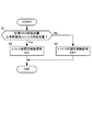
- FIG. 4 is a flowchart for explaining the control contents performed by the bypass valve fixing release signal output unit 107.
- step S1 the controller 4 determines whether or not the target stack supply flow rate is equal to or higher than the dilution request compressor supply flow rate. If the target stack supply flow rate is equal to or higher than the dilution request compressor supply flow rate, the controller 4 performs the process of step S2. On the other hand, if the target stack supply flow rate is less than the dilution request compressor supply flow rate, the process of step S3 is performed.
- step S2 the controller 4 turns on the bypass valve fixing release signal.
- step S3 the controller 4 turns off the bypass valve fixation release signal.
- FIG. 5 is a flowchart for explaining the control contents performed by the bypass valve fixing signal output unit 108.
- step S11 the controller 4 determines whether or not the bypass valve fixing release signal is set to ON. If the bypass valve fixing release signal is set to ON, the controller 4 performs step S12. On the other hand, if the bypass valve fixing release signal is set to OFF, the process of step S14 is performed.
- step S12 the controller 4 turns on the bypass valve closing operation signal regardless of the opening degree of the bypass valve 26. This is because the bypass valve 26 is desired to be fully closed when the bypass valve fixing release signal is set to ON.
- the bypass valve closing operation signal is turned ON, the bypass valve control unit 106 A predetermined value for forcibly closing the bypass valve 26 is input to the deviation used in the PI control.
- the integral calculation for operating the bypass valve 26 in the closing direction is stopped to prevent the windup phenomenon.
- bypass valve 26 is always operated in the closing direction when the bypass valve fixing release signal is set to ON.
- the bypass valve 26 can be kept fully closed.
- step S13 the controller 4 turns off the bypass valve fixing signal.
- step S14 the controller 4 turns off the bypass valve closing operation signal.
- step S15 the controller 4 determines whether or not the actual stack supply flow rate is within the bypass valve fixing range.
- the bypass valve fixed range is a flow rate obtained by adding a predetermined value ⁇ to the target stack supply flow rate (hereinafter referred to as “fixed range upper limit flow rate”) and subtracting the predetermined value ⁇ from the target stack supply flow rate (hereinafter referred to as “fixed”). This is a range having a lower limit of “range lower limit flow rate”.
- the predetermined value ⁇ is a minute value set in consideration of the detection error of the second flow rate sensor 42 that detects the actual stack supply flow rate, the control error of Fordback control, and the like, and the target stack supply flow rate and the fixed range upper limit The flow rate is almost equal.
- the predetermined value ⁇ is larger than the predetermined value ⁇ , and is set to a value substantially equal to the bypass flow rate for the unit opening of the bypass valve 26. If the actual stack supply flow rate is within the bypass valve fixed range, the controller 4 performs the process of step S16. On the other hand, if the actual stack supply flow rate is not within the bypass valve fixed range, the process of step S13 is performed.
- step S16 the controller turns on the bypass valve fixing signal.
- FIG. 6 is a time chart for explaining the operation of controlling the cathode system according to the present embodiment.
- FIG. 6 is a time chart for explaining the operation of controlling the cathode system according to the present embodiment.
- the bypass valve fixation release signal is OFF. Therefore, when the actual stack supply flow rate falls within the bypass valve fixing range at time t6, the bypass valve fixing signal is turned ON.
- the dilution request compressor supply flow rate is set as the target compressor supply flow rate, and the actual stack supply flow rate is larger than the target stack supply flow rate.
- the PI control of the compressor supply flow rate calculation unit 103 the calculation of the deviation time integral is stopped. Therefore, as the deviation between the target stack supply flow rate and the actual stack supply flow rate becomes constant at time t5, the stack required compressor supply flow rate becomes constant (FIG. 6B).
- the bypass valve 26 is opened by the unit opening, and the actual stack supply flow rate becomes smaller than the target stack supply flow rate, so that the time integration of the deviation is performed by PI control in the stack required compressor supply flow rate calculation unit 103. Is resumed. As a result, the stack request compressor supply flow rate gradually increases after time t6 (FIG. 6B).
- the stack request compressor supply flow rate is set as the target compressor supply flow rate.
- the actual stack supply flow rate is smaller than the target stack supply flow rate (FIG. 6A), so the stack required compressor supply flow rate increases. Accordingly, the target compressor supply flow rate will increase accordingly. As a result, the actual stack supply flow rate also increases as the target compressor supply flow rate increases (FIG. 6B).
- the actual stack supply flow rate can be increased to the target stack supply flow rate at time t22.
- the opening of the bypass valve 26 remains fixed (FIGS. 6D and 6E), and the actual stack supply flow rate becomes the target stack supply flow rate. It will be maintained (FIG. 6A).
- the target stack supply flow rate increases toward the ultimate power generation request stack supply flow rate.
- the stack demand compressor supply flow rate also increases (FIG. 6B).
- the stack request compressor supply flow rate is set as the target compressor supply flow rate. Therefore, the cathode compressor having good response is controlled so that the actual compressor supply flow rate becomes the stack required compressor supply flow rate, and the actual stack supply flow rate increases so as to substantially follow the target stack supply flow rate. As a result, the actual stack supply flow rate remains in the bypass valve fixed range (FIG. 6A).
- the bypass valve 26 Can not be closed. As described above, even if the bypass valve 26 can be closed, if the bypass valve 26 is left open, the compressor supply flow rate will increase unnecessarily, resulting in a deterioration in fuel consumption. End up.
- the bypass valve fixing release signal and the bypass valve closing operation signal are turned ON, and the actual stack supply flow rate is within the bypass valve fixing range.
- the bypass valve 26 can be closed even if it is accommodated.
- the bypass valve closing operation signal is turned ON and the bypass valve fixation is performed.
- the signal is turned OFF (FIGS. 6C and 6D; YES in S11, S12, S13).
- the closing side bypass valve operation amount calculated by the bypass valve control unit 106 increases as the bypass valve closing operation signal is turned ON.
- the bypass valve 26 is opened stepwise and the actual stack supply is performed.
- the bypass valve 26 is fixed after the flow rate becomes smaller than the target stack supply flow rate.
- the target compressor supply flow rate is set as the target compressor supply flow rate in the target compressor supply flow rate setting unit 104, in the stack required compressor supply flow rate calculation unit 103, Only when the actual stack supply flow rate is smaller than the target stack supply flow rate (when it is necessary to increase the stack required compressor flow rate), the time integration of the deviation between the target stack flow rate and the actual stack flow rate is performed. When the actual stack supply flow rate is larger than the target stack supply flow rate (when the stack required compressor flow rate needs to be reduced), the time integration of the deviation between the target stack flow rate and the actual stack flow rate is stopped. .
- the deviation between the actual stack supply flow rate and the target stack supply flow rate becomes constant by prohibiting the drive of the bypass valve 26 after the actual stack supply flow rate falls below the target stack supply flow rate. Even in this case, the time integration of the deviation can be performed. Therefore, it is possible to increase the stack demand compressor supply flow rate so that the actual stack supply flow rate matches the target stack supply flow rate. Therefore, since it can suppress that the electrolyte membrane of each fuel cell will be in an overdried state, the fall of power generation efficiency can be suppressed.
- the bypass valve fixing release signal and the bypass valve closing operation signal are turned ON so that the actual stack supply flow rate is within the bypass valve fixing range. Even if there is, the bypass valve 26 can be closed.
- the bypass valve 26 can be closed even when the bypass valve 26 can be fully closed. It can be prevented from disappearing. Therefore, since the compressor supply flow rate does not increase unnecessarily, fuel consumption can be prevented from deteriorating.
- bypass valve 26 is closed by the unit opening when the target stack supply flow rate becomes larger than the dilution request compressor supply flow rate, but it may be controlled to be fully closed.
- the power generation request stack supply flow rate and the wet request stack supply flow rate are input to the target stack supply flow rate calculation unit 103.
- flooding determined according to the load of the fuel cell stack 1 The stack supply flow rate for prevention may be input, and these maximum values may be set as the target stack supply flow rate.
- the target compressor supply flow rate setting unit 104 is input with the dilution request compressor supply flow rate and the stack request compressor supply flow rate.
- the compressor supply flow rate for preventing surging of the cathode compressor 22 is used. These maximum values may be used as the target compressor supply flow rate.
- the cathode compressor control unit 105 performs feedback control based on the target compressor supply flow rate and the actual compressor supply flow rate.
- feedforward control based on the target compressor supply flow rate may be performed. .
- the present application includes Japanese Patent Application No. 2012-43873 filed with the Japan Patent Office on February 29, 2012, Japanese Patent Application No. 2012-45739 filed with the Japan Patent Office on March 1, 2012, and 2013. Claiming priority based on Japanese Patent Application No. 2013-11415 filed with the Japan Patent Office on January 24, 2013, the entire contents of which are incorporated herein by reference.
Landscapes
- Life Sciences & Earth Sciences (AREA)
- Engineering & Computer Science (AREA)
- Manufacturing & Machinery (AREA)
- Sustainable Development (AREA)
- Sustainable Energy (AREA)
- Chemical & Material Sciences (AREA)
- Chemical Kinetics & Catalysis (AREA)
- Electrochemistry (AREA)
- General Chemical & Material Sciences (AREA)
- Fuel Cell (AREA)
Abstract
Description
カソード電極 : 4H+ +4e- +O2 →2H2O …(2)
Claims (6)
- 燃料電池スタックにカソードガスを供給するためのカソードガス供給通路と、
前記燃料電池スタックに供給されたカソードガスを排出するためのカソードガス排出通路と、
前記カソードガス供給通路に設けられるコンプレッサと、
前記コンプレッサから吐出されたカソードガスの一部を、前記燃料電池スタックを迂回させて前記カソードガス排出通路に排出するバイパス通路と、
前記バイパス通路に設けられ、前記バイパス通路を流れるカソードガスの流量を調節するバイパス弁と、
を備える燃料電池システムであって、
前記燃料電池スタックに供給されるスタック供給流量を検出するスタック供給流量検出手段と、
前記燃料電池スタックの要求に基づいて、前記燃料電池スタックに供給すべき目標スタック供給流量を算出する目標スタック供給流量算出手段と、
前記スタック供給流量と、前記目標スタック供給流量と、に基づいて、前記スタック供給流量を前記目標スタック供給流量にするためのスタック要求コンプレッサ供給流量を算出するスタック要求コンプレッサ供給流量算出手段と、
前記スタック要求コンプレッサ供給流量と、前記燃料電池システムの運転状態に応じて定まる下限流量と、の大きいほうを、コンプレッサ供給流量の目標値である目標コンプレッサ供給流量として設定する目標コンプレッサ供給流量設定手段と、
前記目標コンプレッサ供給流量に応じて、前記コンプレッサを制御するコンプレッサ制御手段と、
前記スタック供給流量と前記目標スタック供給流量とに基づいて、前記バイパス弁を制御するバイパス弁制御手段と、
前記スタック供給流量が、前記目標スタック供給流量を基準とした所定のバイパス弁固定範囲内に収まり、かつ、前記スタック供給流量が前記目標スタック供給流量よりも小さくなったときに、前記バイパス弁を固定する固定手段と、
前記固定手段によって前記バイパス弁が固定された後は、前記目標コンプレッサ供給流量が前記下限流量よりも大きくなったときに、前記バイパス弁の固定を解除する固定解除手段と、
を備える燃料電池システム。 - 前記固定解除手段によって前記バイパス弁の固定が解除されたときに、前記バイバス弁を単位開度だけ閉じる、
請求項1に記載の燃料電池システム。 - 前記固定解除手段によって前記バイパス弁の固定が解除されたときに、前記バイバス弁を全閉にする、
請求項1に記載の燃料電池システム。 - 前記スタック要求コンプレッサ供給流量算出手段は、
前記目標コンプレッサ供給流量が前記下限流量に制限されている場合は、前記スタック供給流量が前記目標スタック供給流量よりも小さいときのみ前記スタック供給流量と前記目標スタック供給流量との偏差の時間積分の演算を行うフィードバック制御を実施して、前記スタック要求コンプレッサ供給流量を算出する、
請求項1から請求項3までのいずれか1つに記載の燃料電池システム。 - 前記燃料電池スタックから排出されたアノードガスを、前記カソードガス排出通路に排出するためのアノードガス排出通路をさらに備え、
前記下限流量は、前記カソードガス排出通路内の水素濃度を所定値以下にするために必要なコンプレッサ供給流量の目標値である、
請求項1から請求項4までのいずれか1つに記載の燃料電池システム。 - 前記バイパス弁固定範囲は、
前記目標スタック供給流量から所定値βを減算した規制範囲下限流量から前記目標スタック供給流量から所定値αを加算した規制範囲上限流量までの範囲である、
請求項1から請求項5までのいずれか1つに記載の燃料電池システム。
Priority Applications (5)
| Application Number | Priority Date | Filing Date | Title |
|---|---|---|---|
| CA2865880A CA2865880C (en) | 2012-02-29 | 2013-02-28 | Fuel cell system |
| US14/381,049 US9728794B2 (en) | 2012-02-29 | 2013-02-28 | Fuel cell system |
| JP2014502353A JP5858139B2 (ja) | 2012-02-29 | 2013-02-28 | 燃料電池システム |
| CN201380011594.XA CN104145362B (zh) | 2012-02-29 | 2013-02-28 | 燃料电池系统 |
| EP13754849.1A EP2822072B1 (en) | 2012-02-29 | 2013-02-28 | Fuel cell system |
Applications Claiming Priority (6)
| Application Number | Priority Date | Filing Date | Title |
|---|---|---|---|
| JP2012-043873 | 2012-02-29 | ||
| JP2012043873 | 2012-02-29 | ||
| JP2012-045739 | 2012-03-01 | ||
| JP2012045739 | 2012-03-01 | ||
| JP2013011415 | 2013-01-24 | ||
| JP2013-011415 | 2013-01-24 |
Publications (1)
| Publication Number | Publication Date |
|---|---|
| WO2013129552A1 true WO2013129552A1 (ja) | 2013-09-06 |
Family
ID=49082715
Family Applications (2)
| Application Number | Title | Priority Date | Filing Date |
|---|---|---|---|
| PCT/JP2013/055233 WO2013129521A1 (ja) | 2012-02-29 | 2013-02-27 | 燃料電池システム |
| PCT/JP2013/055347 WO2013129552A1 (ja) | 2012-02-29 | 2013-02-28 | 燃料電池システム |
Family Applications Before (1)
| Application Number | Title | Priority Date | Filing Date |
|---|---|---|---|
| PCT/JP2013/055233 WO2013129521A1 (ja) | 2012-02-29 | 2013-02-27 | 燃料電池システム |
Country Status (6)
| Country | Link |
|---|---|
| US (2) | US9755253B2 (ja) |
| EP (2) | EP2822071B1 (ja) |
| JP (2) | JP5773058B2 (ja) |
| CN (2) | CN104137316B (ja) |
| CA (2) | CA2865877C (ja) |
| WO (2) | WO2013129521A1 (ja) |
Cited By (3)
| Publication number | Priority date | Publication date | Assignee | Title |
|---|---|---|---|---|
| WO2015053156A1 (ja) * | 2013-10-08 | 2015-04-16 | 日産自動車株式会社 | 燃料電池システム |
| JP2015095287A (ja) * | 2013-11-08 | 2015-05-18 | 日産自動車株式会社 | 燃料電池システム |
| JP2017147121A (ja) * | 2016-02-17 | 2017-08-24 | 本田技研工業株式会社 | 燃料電池システムの電力制御方法 |
Families Citing this family (11)
| Publication number | Priority date | Publication date | Assignee | Title |
|---|---|---|---|---|
| KR101592709B1 (ko) * | 2014-06-13 | 2016-02-15 | 현대자동차주식회사 | 차량의 연료전지시스템 및 그 제어방법 |
| JP6278119B2 (ja) * | 2014-08-20 | 2018-02-14 | 日産自動車株式会社 | 燃料電池システム及び燃料電池システムの制御方法 |
| JP6168028B2 (ja) * | 2014-11-05 | 2017-07-26 | トヨタ自動車株式会社 | 燃料電池システム |
| KR101795137B1 (ko) * | 2015-06-03 | 2017-11-08 | 현대자동차주식회사 | 연료전지 스택의 공기 공급 제어 장치 및 그 방법 |
| JP6465307B2 (ja) * | 2016-02-12 | 2019-02-06 | トヨタ自動車株式会社 | 燃料電池システム及びその制御方法 |
| JP6329976B2 (ja) * | 2016-02-26 | 2018-05-23 | 本田技研工業株式会社 | 燃料電池システム |
| KR101843749B1 (ko) * | 2016-04-15 | 2018-03-30 | 현대자동차주식회사 | 연료전지 시스템, 이를 포함하는 차량 및 연료전지 시스템의 제어방법 |
| US11482719B2 (en) * | 2017-12-08 | 2022-10-25 | Toyota Jidosha Kabushiki Kaisha | Equation based state estimate for air system controller |
| CN108177539B (zh) * | 2017-12-28 | 2020-10-30 | 潍柴动力股份有限公司 | 一种燃料电池电动汽车的空气压缩系统及控制方法 |
| US10862143B2 (en) * | 2019-01-30 | 2020-12-08 | Toyota Jidosha Kabushiki Kaisha | Turbo compressor path and rate control |
| CN110137544B (zh) * | 2019-04-18 | 2021-12-24 | 上海交通大学 | 质子交换膜燃料电池电堆反应状态在线检测系统及其应用 |
Citations (4)
| Publication number | Priority date | Publication date | Assignee | Title |
|---|---|---|---|---|
| JP2007317472A (ja) * | 2006-05-25 | 2007-12-06 | Toyota Motor Corp | 燃料電池システム |
| JP2009123550A (ja) | 2007-11-15 | 2009-06-04 | Toyota Motor Corp | 燃料電池システム |
| JP2009283409A (ja) * | 2008-05-26 | 2009-12-03 | Nissan Motor Co Ltd | 燃料電池システムおよび燃料電池システムの制御方法 |
| WO2011148426A1 (ja) * | 2010-05-27 | 2011-12-01 | トヨタ自動車株式会社 | 燃料電池システム |
Family Cites Families (13)
| Publication number | Priority date | Publication date | Assignee | Title |
|---|---|---|---|---|
| JPH0772653B2 (ja) * | 1989-03-27 | 1995-08-02 | ダイキン工業株式会社 | 空気調和装置の運転制御装置 |
| JP3804204B2 (ja) * | 1997-08-18 | 2006-08-02 | 石川島播磨重工業株式会社 | 多段タービン圧縮機を備えた燃料電池発電装置 |
| JP3820992B2 (ja) * | 2002-01-08 | 2006-09-13 | 日産自動車株式会社 | 燃料電池システム |
| JP3882617B2 (ja) * | 2002-01-11 | 2007-02-21 | 日産自動車株式会社 | 燃料電池システム |
| JP4737977B2 (ja) * | 2004-11-30 | 2011-08-03 | 株式会社ケーヒン | 燃料電池用弁装置 |
| JP2007257956A (ja) * | 2006-03-22 | 2007-10-04 | Nissan Motor Co Ltd | 燃料電池システム |
| JP5266620B2 (ja) * | 2006-04-07 | 2013-08-21 | トヨタ自動車株式会社 | 燃料電池運転システム及び燃料電池運転システムにおける弁開度算出方法 |
| JP2008016399A (ja) * | 2006-07-10 | 2008-01-24 | Toyota Motor Corp | 燃料電池システム |
| JP5105223B2 (ja) * | 2006-12-27 | 2012-12-26 | トヨタ自動車株式会社 | 燃料電池システム |
| JP2009076243A (ja) | 2007-09-19 | 2009-04-09 | Toyota Motor Corp | 燃料電池システム |
| US9034530B2 (en) * | 2008-08-06 | 2015-05-19 | GM Global Technology Operations LLC | Fuel cell stack used as coolant heater |
| JP5493466B2 (ja) * | 2009-05-21 | 2014-05-14 | トヨタ自動車株式会社 | 燃料電池システム |
| WO2011135610A1 (ja) * | 2010-04-27 | 2011-11-03 | トヨタ自動車株式会社 | 燃料電池システム |
-
2013
- 2013-02-27 CA CA2865877A patent/CA2865877C/en active Active
- 2013-02-27 US US14/381,779 patent/US9755253B2/en active Active
- 2013-02-27 JP JP2014502335A patent/JP5773058B2/ja not_active Expired - Fee Related
- 2013-02-27 WO PCT/JP2013/055233 patent/WO2013129521A1/ja active Application Filing
- 2013-02-27 EP EP13754461.5A patent/EP2822071B1/en active Active
- 2013-02-27 CN CN201380011562.XA patent/CN104137316B/zh active Active
- 2013-02-28 EP EP13754849.1A patent/EP2822072B1/en active Active
- 2013-02-28 CA CA2865880A patent/CA2865880C/en active Active
- 2013-02-28 CN CN201380011594.XA patent/CN104145362B/zh active Active
- 2013-02-28 WO PCT/JP2013/055347 patent/WO2013129552A1/ja active Application Filing
- 2013-02-28 US US14/381,049 patent/US9728794B2/en active Active
- 2013-02-28 JP JP2014502353A patent/JP5858139B2/ja active Active
Patent Citations (4)
| Publication number | Priority date | Publication date | Assignee | Title |
|---|---|---|---|---|
| JP2007317472A (ja) * | 2006-05-25 | 2007-12-06 | Toyota Motor Corp | 燃料電池システム |
| JP2009123550A (ja) | 2007-11-15 | 2009-06-04 | Toyota Motor Corp | 燃料電池システム |
| JP2009283409A (ja) * | 2008-05-26 | 2009-12-03 | Nissan Motor Co Ltd | 燃料電池システムおよび燃料電池システムの制御方法 |
| WO2011148426A1 (ja) * | 2010-05-27 | 2011-12-01 | トヨタ自動車株式会社 | 燃料電池システム |
Non-Patent Citations (1)
| Title |
|---|
| See also references of EP2822072A4 * |
Cited By (8)
| Publication number | Priority date | Publication date | Assignee | Title |
|---|---|---|---|---|
| WO2015053156A1 (ja) * | 2013-10-08 | 2015-04-16 | 日産自動車株式会社 | 燃料電池システム |
| CN105612646A (zh) * | 2013-10-08 | 2016-05-25 | 日产自动车株式会社 | 燃料电池系统 |
| EP3057167A4 (en) * | 2013-10-08 | 2016-10-12 | Nissan Motor | FUEL CELL SYSTEM |
| JPWO2015053156A1 (ja) * | 2013-10-08 | 2017-03-09 | 日産自動車株式会社 | 燃料電池システム |
| US9847538B2 (en) | 2013-10-08 | 2017-12-19 | Nissan Motor Co., Ltd. | Fuel cell system |
| CN105612646B (zh) * | 2013-10-08 | 2018-01-09 | 日产自动车株式会社 | 燃料电池系统 |
| JP2015095287A (ja) * | 2013-11-08 | 2015-05-18 | 日産自動車株式会社 | 燃料電池システム |
| JP2017147121A (ja) * | 2016-02-17 | 2017-08-24 | 本田技研工業株式会社 | 燃料電池システムの電力制御方法 |
Also Published As
| Publication number | Publication date |
|---|---|
| CA2865880A1 (en) | 2013-09-06 |
| CA2865880C (en) | 2016-09-20 |
| JPWO2013129552A1 (ja) | 2015-07-30 |
| CN104145362A (zh) | 2014-11-12 |
| EP2822071A4 (en) | 2015-04-08 |
| WO2013129521A1 (ja) | 2013-09-06 |
| JP5773058B2 (ja) | 2015-09-02 |
| EP2822072A1 (en) | 2015-01-07 |
| CN104145362B (zh) | 2016-11-02 |
| CA2865877C (en) | 2017-01-10 |
| US9728794B2 (en) | 2017-08-08 |
| US20150030953A1 (en) | 2015-01-29 |
| JP5858139B2 (ja) | 2016-02-10 |
| JPWO2013129521A1 (ja) | 2015-07-30 |
| CA2865877A1 (en) | 2013-09-06 |
| EP2822071A1 (en) | 2015-01-07 |
| US9755253B2 (en) | 2017-09-05 |
| CN104137316A (zh) | 2014-11-05 |
| EP2822072B1 (en) | 2018-01-03 |
| US20150037701A1 (en) | 2015-02-05 |
| CN104137316B (zh) | 2016-10-19 |
| EP2822072A4 (en) | 2015-04-08 |
| EP2822071B1 (en) | 2017-06-28 |
Similar Documents
| Publication | Publication Date | Title |
|---|---|---|
| JP5858139B2 (ja) | 燃料電池システム | |
| JP5796680B2 (ja) | 燃料電池システム | |
| JP6065117B2 (ja) | 燃料電池システム及び燃料電池システムの制御方法 | |
| JP6079788B2 (ja) | 燃料電池システム | |
| WO2015005229A1 (ja) | 燃料電池システム及び燃料電池システムの制御方法 | |
| WO2015053156A1 (ja) | 燃料電池システム | |
| WO2014148153A1 (ja) | 燃料電池システム及び燃料電池システムの制御方法 | |
| JP6064623B2 (ja) | 燃料電池システム | |
| JP2009301803A (ja) | 燃料電池システムおよび燃料電池システムの制御方法 | |
| JP6090451B2 (ja) | 燃料電池システム及び燃料電池システムの制御方法 | |
| JP6064622B2 (ja) | 燃料電池システム | |
| JP2009004160A (ja) | 燃料電池システム |
Legal Events
| Date | Code | Title | Description |
|---|---|---|---|
| 121 | Ep: the epo has been informed by wipo that ep was designated in this application |
Ref document number: 13754849 Country of ref document: EP Kind code of ref document: A1 |
|
| WWE | Wipo information: entry into national phase |
Ref document number: 14381049 Country of ref document: US |
|
| ENP | Entry into the national phase |
Ref document number: 2014502353 Country of ref document: JP Kind code of ref document: A |
|
| ENP | Entry into the national phase |
Ref document number: 2865880 Country of ref document: CA |
|
| NENP | Non-entry into the national phase |
Ref country code: DE |
|
| WWE | Wipo information: entry into national phase |
Ref document number: 2013754849 Country of ref document: EP |