WO2013129089A1 - 船舶用排ガス脱硝反応容器および船舶用脱硝設備 - Google Patents
船舶用排ガス脱硝反応容器および船舶用脱硝設備 Download PDFInfo
- Publication number
- WO2013129089A1 WO2013129089A1 PCT/JP2013/053186 JP2013053186W WO2013129089A1 WO 2013129089 A1 WO2013129089 A1 WO 2013129089A1 JP 2013053186 W JP2013053186 W JP 2013053186W WO 2013129089 A1 WO2013129089 A1 WO 2013129089A1
- Authority
- WO
- WIPO (PCT)
- Prior art keywords
- exhaust gas
- partition plate
- denitration
- container
- axial direction
- Prior art date
- Legal status (The legal status is an assumption and is not a legal conclusion. Google has not performed a legal analysis and makes no representation as to the accuracy of the status listed.)
- Ceased
Links
Images








Classifications
-
- B—PERFORMING OPERATIONS; TRANSPORTING
- B01—PHYSICAL OR CHEMICAL PROCESSES OR APPARATUS IN GENERAL
- B01D—SEPARATION
- B01D53/00—Separation of gases or vapours; Recovering vapours of volatile solvents from gases; Chemical or biological purification of waste gases, e.g. engine exhaust gases, smoke, fumes, flue gases, aerosols
- B01D53/34—Chemical or biological purification of waste gases
- B01D53/92—Chemical or biological purification of waste gases of engine exhaust gases
- B01D53/94—Chemical or biological purification of waste gases of engine exhaust gases by catalytic processes
- B01D53/9404—Removing only nitrogen compounds
- B01D53/9409—Nitrogen oxides
- B01D53/9431—Processes characterised by a specific device
-
- F—MECHANICAL ENGINEERING; LIGHTING; HEATING; WEAPONS; BLASTING
- F01—MACHINES OR ENGINES IN GENERAL; ENGINE PLANTS IN GENERAL; STEAM ENGINES
- F01N—GAS-FLOW SILENCERS OR EXHAUST APPARATUS FOR MACHINES OR ENGINES IN GENERAL; GAS-FLOW SILENCERS OR EXHAUST APPARATUS FOR INTERNAL-COMBUSTION ENGINES
- F01N3/00—Exhaust or silencing apparatus having means for purifying, rendering innocuous, or otherwise treating exhaust
- F01N3/08—Exhaust or silencing apparatus having means for purifying, rendering innocuous, or otherwise treating exhaust for rendering innocuous
-
- B—PERFORMING OPERATIONS; TRANSPORTING
- B01—PHYSICAL OR CHEMICAL PROCESSES OR APPARATUS IN GENERAL
- B01D—SEPARATION
- B01D53/00—Separation of gases or vapours; Recovering vapours of volatile solvents from gases; Chemical or biological purification of waste gases, e.g. engine exhaust gases, smoke, fumes, flue gases, aerosols
- B01D53/34—Chemical or biological purification of waste gases
- B01D53/92—Chemical or biological purification of waste gases of engine exhaust gases
- B01D53/94—Chemical or biological purification of waste gases of engine exhaust gases by catalytic processes
-
- B—PERFORMING OPERATIONS; TRANSPORTING
- B63—SHIPS OR OTHER WATERBORNE VESSELS; RELATED EQUIPMENT
- B63J—AUXILIARIES ON VESSELS
- B63J99/00—Subject matter not provided for in other groups of this subclass
-
- F—MECHANICAL ENGINEERING; LIGHTING; HEATING; WEAPONS; BLASTING
- F01—MACHINES OR ENGINES IN GENERAL; ENGINE PLANTS IN GENERAL; STEAM ENGINES
- F01N—GAS-FLOW SILENCERS OR EXHAUST APPARATUS FOR MACHINES OR ENGINES IN GENERAL; GAS-FLOW SILENCERS OR EXHAUST APPARATUS FOR INTERNAL-COMBUSTION ENGINES
- F01N13/00—Exhaust or silencing apparatus characterised by constructional features
- F01N13/004—Exhaust or silencing apparatus characterised by constructional features specially adapted for marine propulsion, i.e. for receiving simultaneously engine exhaust gases and engine cooling water
-
- F—MECHANICAL ENGINEERING; LIGHTING; HEATING; WEAPONS; BLASTING
- F01—MACHINES OR ENGINES IN GENERAL; ENGINE PLANTS IN GENERAL; STEAM ENGINES
- F01N—GAS-FLOW SILENCERS OR EXHAUST APPARATUS FOR MACHINES OR ENGINES IN GENERAL; GAS-FLOW SILENCERS OR EXHAUST APPARATUS FOR INTERNAL-COMBUSTION ENGINES
- F01N13/00—Exhaust or silencing apparatus characterised by constructional features
- F01N13/08—Other arrangements or adaptations of exhaust conduits
- F01N13/087—Other arrangements or adaptations of exhaust conduits having valves upstream of silencing apparatus for by-passing at least part of exhaust directly to atmosphere
-
- F—MECHANICAL ENGINEERING; LIGHTING; HEATING; WEAPONS; BLASTING
- F01—MACHINES OR ENGINES IN GENERAL; ENGINE PLANTS IN GENERAL; STEAM ENGINES
- F01N—GAS-FLOW SILENCERS OR EXHAUST APPARATUS FOR MACHINES OR ENGINES IN GENERAL; GAS-FLOW SILENCERS OR EXHAUST APPARATUS FOR INTERNAL-COMBUSTION ENGINES
- F01N13/00—Exhaust or silencing apparatus characterised by constructional features
- F01N13/18—Construction facilitating manufacture, assembly, or disassembly
- F01N13/1805—Fixing exhaust manifolds, exhaust pipes or pipe sections to each other, to engine or to vehicle body
- F01N13/1811—Fixing exhaust manifolds, exhaust pipes or pipe sections to each other, to engine or to vehicle body with means permitting relative movement, e.g. compensation of thermal expansion or vibration
-
- F—MECHANICAL ENGINEERING; LIGHTING; HEATING; WEAPONS; BLASTING
- F01—MACHINES OR ENGINES IN GENERAL; ENGINE PLANTS IN GENERAL; STEAM ENGINES
- F01N—GAS-FLOW SILENCERS OR EXHAUST APPARATUS FOR MACHINES OR ENGINES IN GENERAL; GAS-FLOW SILENCERS OR EXHAUST APPARATUS FOR INTERNAL-COMBUSTION ENGINES
- F01N3/00—Exhaust or silencing apparatus having means for purifying, rendering innocuous, or otherwise treating exhaust
- F01N3/08—Exhaust or silencing apparatus having means for purifying, rendering innocuous, or otherwise treating exhaust for rendering innocuous
- F01N3/10—Exhaust or silencing apparatus having means for purifying, rendering innocuous, or otherwise treating exhaust for rendering innocuous by thermal or catalytic conversion of noxious components of exhaust
- F01N3/18—Exhaust or silencing apparatus having means for purifying, rendering innocuous, or otherwise treating exhaust for rendering innocuous by thermal or catalytic conversion of noxious components of exhaust characterised by methods of operation; Control
- F01N3/20—Exhaust or silencing apparatus having means for purifying, rendering innocuous, or otherwise treating exhaust for rendering innocuous by thermal or catalytic conversion of noxious components of exhaust characterised by methods of operation; Control specially adapted for catalytic conversion
-
- F—MECHANICAL ENGINEERING; LIGHTING; HEATING; WEAPONS; BLASTING
- F01—MACHINES OR ENGINES IN GENERAL; ENGINE PLANTS IN GENERAL; STEAM ENGINES
- F01N—GAS-FLOW SILENCERS OR EXHAUST APPARATUS FOR MACHINES OR ENGINES IN GENERAL; GAS-FLOW SILENCERS OR EXHAUST APPARATUS FOR INTERNAL-COMBUSTION ENGINES
- F01N3/00—Exhaust or silencing apparatus having means for purifying, rendering innocuous, or otherwise treating exhaust
- F01N3/08—Exhaust or silencing apparatus having means for purifying, rendering innocuous, or otherwise treating exhaust for rendering innocuous
- F01N3/10—Exhaust or silencing apparatus having means for purifying, rendering innocuous, or otherwise treating exhaust for rendering innocuous by thermal or catalytic conversion of noxious components of exhaust
- F01N3/18—Exhaust or silencing apparatus having means for purifying, rendering innocuous, or otherwise treating exhaust for rendering innocuous by thermal or catalytic conversion of noxious components of exhaust characterised by methods of operation; Control
- F01N3/20—Exhaust or silencing apparatus having means for purifying, rendering innocuous, or otherwise treating exhaust for rendering innocuous by thermal or catalytic conversion of noxious components of exhaust characterised by methods of operation; Control specially adapted for catalytic conversion
- F01N3/206—Adding periodically or continuously substances to exhaust gases for promoting purification, e.g. catalytic material in liquid form, NOx reducing agents
- F01N3/2066—Selective catalytic reduction [SCR]
-
- F—MECHANICAL ENGINEERING; LIGHTING; HEATING; WEAPONS; BLASTING
- F01—MACHINES OR ENGINES IN GENERAL; ENGINE PLANTS IN GENERAL; STEAM ENGINES
- F01N—GAS-FLOW SILENCERS OR EXHAUST APPARATUS FOR MACHINES OR ENGINES IN GENERAL; GAS-FLOW SILENCERS OR EXHAUST APPARATUS FOR INTERNAL-COMBUSTION ENGINES
- F01N3/00—Exhaust or silencing apparatus having means for purifying, rendering innocuous, or otherwise treating exhaust
- F01N3/08—Exhaust or silencing apparatus having means for purifying, rendering innocuous, or otherwise treating exhaust for rendering innocuous
- F01N3/10—Exhaust or silencing apparatus having means for purifying, rendering innocuous, or otherwise treating exhaust for rendering innocuous by thermal or catalytic conversion of noxious components of exhaust
- F01N3/24—Exhaust or silencing apparatus having means for purifying, rendering innocuous, or otherwise treating exhaust for rendering innocuous by thermal or catalytic conversion of noxious components of exhaust characterised by constructional aspects of converting apparatus
-
- B—PERFORMING OPERATIONS; TRANSPORTING
- B01—PHYSICAL OR CHEMICAL PROCESSES OR APPARATUS IN GENERAL
- B01D—SEPARATION
- B01D2259/00—Type of treatment
- B01D2259/45—Gas separation or purification devices adapted for specific applications
- B01D2259/4566—Gas separation or purification devices adapted for specific applications for use in transportation means
-
- F—MECHANICAL ENGINEERING; LIGHTING; HEATING; WEAPONS; BLASTING
- F01—MACHINES OR ENGINES IN GENERAL; ENGINE PLANTS IN GENERAL; STEAM ENGINES
- F01N—GAS-FLOW SILENCERS OR EXHAUST APPARATUS FOR MACHINES OR ENGINES IN GENERAL; GAS-FLOW SILENCERS OR EXHAUST APPARATUS FOR INTERNAL-COMBUSTION ENGINES
- F01N2610/00—Adding substances to exhaust gases
- F01N2610/02—Adding substances to exhaust gases the substance being ammonia or urea
-
- Y—GENERAL TAGGING OF NEW TECHNOLOGICAL DEVELOPMENTS; GENERAL TAGGING OF CROSS-SECTIONAL TECHNOLOGIES SPANNING OVER SEVERAL SECTIONS OF THE IPC; TECHNICAL SUBJECTS COVERED BY FORMER USPC CROSS-REFERENCE ART COLLECTIONS [XRACs] AND DIGESTS
- Y02—TECHNOLOGIES OR APPLICATIONS FOR MITIGATION OR ADAPTATION AGAINST CLIMATE CHANGE
- Y02T—CLIMATE CHANGE MITIGATION TECHNOLOGIES RELATED TO TRANSPORTATION
- Y02T10/00—Road transport of goods or passengers
- Y02T10/10—Internal combustion engine [ICE] based vehicles
- Y02T10/12—Improving ICE efficiencies
Definitions
- the present invention includes an evaporation chamber for blowing urea water or ammonia water into exhaust gas discharged from a diesel engine mounted on a ship, and a reaction chamber having a catalyst unit for removing nitrogen oxides in contact with the exhaust gas.
- the present invention relates to a marine exhaust gas denitration reaction vessel and a marine exhaust gas denitration facility equipped with the denitration reaction vessel. About.
- the ship is equipped with a large diesel engine.
- an evaporation chamber for blowing urea water or ammonia water, which is a denitration reducing agent, into the exhaust gas, and a denitration catalyst that removes NOx A denitration reactor in which the reaction chamber in which the catalyst elements are arranged is installed in one reaction vessel is conceivable.
- the present invention provides a marine vessel capable of effectively absorbing a thermal expansion difference due to a temperature difference between an evaporation chamber and a reaction chamber in a denitration reactor in which an evaporation chamber and a reaction chamber are integrally provided, and preventing damage due to thermal distortion.
- An object of the present invention is to provide an exhaust gas denitration reaction vessel and a marine exhaust gas denitration facility equipped with the denitration reaction vessel.
- An exhaust gas denitration reaction vessel In the vessel body of the reaction vessel, a partition wall that partitions the evaporation chamber and the reaction chamber is provided along the vessel axial direction, and an untreated gas outlet is provided in the evaporator.
- the partition wall is a thermal expansion absorption structure capable of expanding and contracting in a direction along the transverse axis of the container axis and the reaction container to absorb the difference in thermal expansion between the evaporation chamber and the reaction chamber components
- the thermal expansion absorption structure is Constantly between the main partition plate attached to the evaporation chamber side and the main partition plate attached to the reaction chamber side on the partition wall base material along the axial direction of the container on the inner surface of the shell of the container body
- a double wall structure including a sub partition plate disposed with a gap and attached with the catalyst unit, and a container between the partition base material, the main partition plate, and the sub partition plate
- An axial direction slide mechanism that is movable in a predetermined range in the axial direction, and further, at the front and rear end portions in the exhaust gas flow direction of the auxiliary partition plate, between the auxiliary partition plate and the main divider plate,
- a movable seal portion capable of following displacement due to thermal expansion in a container axial direction of the sub partition plate and
- the invention of claim 2 is the configuration of claim 1,
- the axial direction sliding mechanism includes the main partition plate and the sub-partition plate, a guide portion formed on one side of the partition base material in the container axial direction, and formed on the other side so as to be slidable on the guide portion. And a guided member to be engaged.
- the invention according to claim 3 is the configuration according to claim 1 or 2
- the movable seal portion includes an elastic seal plate having a fixed end attached to one end portion of the main partition plate and the sub partition plate and a free end side slidably in contact with the other.
- the invention according to claim 4 A marine exhaust gas denitration reaction vessel according to any one of claims 1 to 3, An exhaust gas supercharger that supplies exhaust gas from the reaction chamber to the intake port via a denitration gas discharge pipe; A bypass pipe connecting the air supply port of the exhaust gas supercharger and the untreated gas outlet of the evaporation chamber; An exhaust gas switching valve capable of opening and closing the bypass pipe; A gas shutoff valve interposed at least in the denitration gas discharge pipe and capable of opening and closing the denitration gas discharge pipe,
- the evaporation chamber is also used as a manifold for joining exhaust gases discharged from a plurality of diesel engines and supplying the exhaust gas to the exhaust gas supercharger.
- the reaction chamber and the evaporation chamber partitioned by the partition are integrally provided in the reaction vessel.
- the expansion-contraction of the direction along the cross section of a container is absorbed by making into the thermal expansion absorption structure of the said partition the double wall structure which has arrange
- the expansion and contraction in the container axial direction is absorbed by the axial direction slide mechanism provided at the attachment portion of the partition wall substrate, the main partition plate, and the sub partition plate.
- the evaporation chamber may be in a high temperature state and the reaction chamber may be in a low temperature state during non-denitration processing in which the exhaust gas is not introduced into the reaction chamber.
- the expansion and contraction can be effectively absorbed by the thermal expansion absorption structure of the partition wall, and it is possible to prevent the constituent members of the reaction vessel from being damaged due to thermal distortion.
- the axial direction sliding mechanism is constituted by the guide portion and the guided portion that is slidably engaged with the guide portion, so that the thermal expansion of the main partition plate and the sub partition plate is achieved.
- the expansion and contraction in the axial direction due to the difference can be effectively absorbed.
- the elastic seal plate is provided between the sub partition plate and the main partition plate at the front and rear end portions of the sub partition plate, the container axial direction of the sub partition plate and the main partition plate
- the elastic seal plate is deformed corresponding to the displacement due to the thermal expansion in the direction along the cross section of the container, and can follow the displacement of the sub partition plate or the main partition plate, and the gap between the main partition plate and the sub partition plate Can be reliably sealed, and exhaust gas blow-through can be reliably prevented.
- the exhaust gas switching valve is opened to connect the bypass pipe, and the gas shut-off valve is closed to connect the communication portion and the denitration gas discharge. Shut off the tube.
- the exhaust gas discharged from the plurality of diesel engines and joined in the evaporation chamber can be introduced into the exhaust gas supercharger from the untreated exhaust port of the evaporation chamber via the bypass pipe.
- a temperature difference occurs between the evaporation chamber into which the exhaust gas is introduced and the reaction chamber into which the exhaust gas is not introduced.
- the double wall structure which is a part of the thermal expansion absorption structure of the partition wall can absorb the expansion and contraction difference in the direction along the transverse section of the partition wall container.
- the expansion-contraction difference of a container axial direction can be absorbed with the axial direction sliding mechanism which is the remainder of the thermal expansion absorption structure of a partition. Therefore, it is possible to effectively absorb the thermal strain due to the temperature difference between the evaporation chamber and the reaction chamber, and to prevent the constituent members of the reaction vessel from being damaged by the thermal strain.
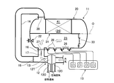
- FIG. 1 is a configuration diagram showing a marine exhaust gas denitration facility for denitrating exhaust gas discharged from a combustion chamber of a marine diesel engine 13 according to the present invention.
- 11 is a denitration reaction vessel (reaction vessel)
- 12 is an exhaust gas supercharger driven by the exhaust gas of the diesel engine 13.
- a partition wall 21 along the container axis O direction is installed in the container main body 20 of the denitration reaction container 11, and the evaporation chamber 23 and the reaction chamber 25 are accommodated integrally in the container main body 20.
- an evaporation chamber 23 for injecting urea water (or ammonia water) into the exhaust gas is formed in the lower part of the partition wall 21, and the exhaust gas in which urea water is injected in the upper part of the partition wall 21 is brought into contact with a plurality of catalyst units 24.
- a reaction chamber 25 for reducing NOx is formed.
- the container body 20 of the denitration reaction container 11 is formed in a pressure resistant container in which both ends of a cylindrical shell body 20B are closed by curved pressure-proof end plates 20R, 20L, for example.
- a plurality of exhaust gas inlets 26 for introducing exhaust gas into the evaporation chamber 23 are formed at the bottom of the shell 20B. Then, exhaust gases discharged from a plurality of (four chambers in the figure) combustion chambers of the diesel engine 13 are respectively introduced into the evaporation chambers through the exhaust gas inlets 26.
- the evaporation chamber 23 is also used as an exhaust gas manifold that joins exhaust gases introduced from a plurality of exhaust gas inlets 26.
- the exhaust gas supercharger 12 includes a turbine unit 12T and a compressor unit 12C that are connected to each other by an input / output shaft.
- the turbine section 12T untreated exhaust gas or denitration exhaust gas discharged from the combustion chamber of the diesel engine 13 via the denitration reaction vessel 11 is supplied to the air inlet 12i.
- the exhaust gas discharged from the exhaust port 12o of the turbine unit 12T is discharged from the exhaust chimney.
- the compressor unit 12C the atmosphere is sucked and pressurized from the intake port, and the pressurized air is supplied to the combustion chamber of the diesel engine 13 from the exhaust port as combustion air.
- a denitration gas discharge pipe 14 is connected between the denitration gas outlet 28 of the denitration reaction vessel 11 and the air supply port 12i of the turbine section 12T.
- a bypass pipe 16 connected to the untreated gas outlet 27 of the denitration reaction vessel 11 is connected to the vicinity of the air inlet 12 i of the denitration gas discharge pipe 14.
- a denitration outlet valve (gas cutoff valve) 15 comprising a butterfly valve is provided in the denitration gas discharge pipe 14 upstream of the connection portion between the denitration gas discharge pipe 14 and the bypass pipe 16.
- the denitration outlet valve 15 is configured to close the denitration gas discharge pipe 14.
- the bypass pipe 16 is provided with an exhaust gas switching valve 17 composed of a butterfly valve capable of opening and closing the bypass pipe 16.
- a spray nozzle 22 that blows urea water or ammonia water into the exhaust gas in the evaporation chamber 23 is disposed on one end plate 20 ⁇ / b> L of the container body 20.
- a communication portion 30 is formed on the other end plate 20 ⁇ / b> R side of the container body 20.
- This communication part 30 is arranged between the partition wall 21 and the shell 20B of the evaporation chamber 23 along the cross section of the reaction vessel 11, and a partition wall 31 for closing the evaporation chamber 23, and the partition wall 21 (the partition wall 31).
- an evaporation chamber outlet valve (gas shutoff valve) 33 provided at the opening of the partition wall 31, and an evaporation formed on the partition wall 31.
- the chamber 23 and the reaction chamber 25 are composed of one or a plurality of pressure adjusting ports 34 for adjusting the pressure to be equal.
- the ventilation resistance of the reaction chamber 25 and the denitration gas discharge pipe 14 is reduced by closing the denitration outlet valve 15 of the denitration gas discharge pipe 14 in a state where the evaporation chamber outlet valve 33 is deleted and the opening is opened.
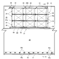
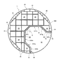
- a unit assembly 41 is installed in the reaction chamber 25.
- a plurality of catalyst units 24 are stacked in the vertical and horizontal directions between the partition wall 21 and the shell body 20B, and are connected in the container axis O direction.
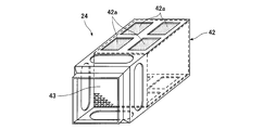
- these catalyst units 24 include a storage frame body 42 in which notched holes 42 a are formed on opposing side surfaces, and a catalyst element 43 having a honeycomb-shaped cross section accommodated in the storage frame body 42.
- a cross-sectional form of these unit aggregates 41 a rectangular cross section or a trapezoidal cross section shown in FIG. 13 is adopted.
- the unit assembly 41 is supported in the shell 20B through a plurality of outer peripheral supports 44 that adjust the distance between the shell 20B and the unit assembly 41.
- an outer peripheral closing plate 46 that closes the fixture 45 and the space between the shell 20 ⁇ / b> B and the unit assembly 41 is disposed on one end side (downstream side of the exhaust gas flow) of the reaction chamber 25.
- a presser 47 is disposed on the other end side of the reaction chamber 25 (upstream side of the exhaust gas flow).
- the unit assembly 41 is held in the shell 20B by the outer peripheral support tool 44, the fixing tool 45, the outer peripheral closing plate 46, and the pressing tool 47. Note that the cross-sectional line AA in FIG. 4 indicates the cross-sectional position in FIG.
- the outer peripheral support 44 includes a pair of tapered sleeves 44a and 44b which are cut by an inclined surface inclined at a predetermined angle with respect to an axis parallel to the container axis O and slidable on the inclined surface.
- One of the taper sleeves 44 a and 44 b is attached to the storage frame 42 of the catalyst unit 24.
- the other taper sleeve 44b is attached to the shell 20B via a connecting member 44c.
- the connecting bolt / nut 44d is loosely fitted in the shaft holes 44e, 44f of the tapered sleeves 44a, 44b, and the sliding limit of the tapered sleeves 44a, 44b is restricted by the connecting bolt / nut 44d.
- the expansion and contraction difference in the container axis O direction due to thermal expansion of the shell 20B and the unit assembly 41 can be absorbed within the sliding range of the taper sleeves 44a and 44b by the connecting bolt / nut 44d.
- These outer peripheral support tools 44 support the outer peripheral portion of the unit assembly 41 between the shell body 20 ⁇ / b> B and the partition wall 21.
- the fixture 45 installed at the downstream end of the exhaust gas flow of the unit assembly 41 is a substantially lattice-shaped plate corresponding to the arrangement pattern (FIG. 3) of the catalyst unit 24 as shown in the right part of FIG. 11 and FIG.
- a frame body 45a is provided.
- the plate-like frame body 45a has a chamfered front end that comes into contact with a contact portion between adjacent catalyst units 24.
- the outer peripheral edge part of the plate-shaped frame 45a is each connected and fixed to the shell 20B by the attachment member 45b, and the unit assembly 41 is restricted from moving to the downstream side of the exhaust gas.
- the outer periphery closing plate 46 is installed on the downstream side of the attachment member 45b to shield the exhaust gas.
- the outer edge part of the plate-shaped frame 45a is formed in the half cross-sectional shape.
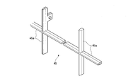
- the presser 47 installed at the upstream end of the exhaust gas flow of the unit assembly 41 is an integral substantially grid-like linear shape corresponding to the arrangement pattern of the catalyst units 24 (FIG. 3).
- a frame 47a is provided.
- the linear frame 47a is formed in a rod shape having a circular cross section, and is fitted into a taper groove formed in front of the contact portion between the adjacent catalyst units 24.
- maintenance bolt 47c of the container axis O direction is fitted by the bracket 47b standingly arranged by the trunk
- the presser bolt 47c is fixed in a pressurized state by a lock nut 47d, and the linear frame body 47a is pressed against the catalyst unit 24 through the presser plate 47e at the tip of the presser bolt 47c.
- the unit assembly 41 is positioned and fixed in the direction of the container axis O between the pressing tool 47 and the fixing tool 45.
- the substantially grid-like linear frame body 47a has an integral structure.
- the linear frame body 47a may be divided into a plurality of divided structures along the vertical and horizontal cross sections, and may be assembled and used. Good.
- the partition wall 21 installed in the shell body 20B in the container body 20 has a vertical wall portion 21V and a horizontal wall portion connected in an L shape with the vicinity of the container axis O as a corner portion.
- the container main body 20 is formed in a cylindrical shape, it may be a cylindrical shape such as a square tube or a polygonal tube shape of pentagon or higher.
- the partition wall 21 is configured to have a thermal expansion absorption structure that expands and contracts in the direction along the container axis O and the cross section of the container, and can absorb the thermal expansion difference of the constituent members due to the temperature difference between the evaporation chamber 23 and the reaction chamber 25. ing.
- the partition wall 21 has a partition wall base 51 attached to the inner surface of the shell 20B along the container axis O direction.
- the partition wall base 51 is attached with a certain gap 54 between the main partition plate 52 attached to the evaporation chamber side and the main partition plate 52 on the reaction chamber 25 side of the partition wall base 51.
- the sub partition plate 53 is provided, and is formed in a double wall structure including the main partition plate 52 and the sub partition plate 53. In this double wall structure, a fixed gap 54 is held by the partition wall base material 51 and the thermal expansion (difference) in the direction along the transverse cross section of the main and sub partition plates 52 and 53 can be absorbed.
- An axial direction slide mechanism 55 that can absorb thermal expansion in the container axis O direction within a predetermined range is provided between the partition wall base 51 and the main partition plate 52 and the sub partition plate 53. That is, as shown in FIG. 6, the axial direction sliding mechanism 55 includes a plurality of adjustment bolts (guided portions) 55a penetrating in the container tangent direction at regular intervals in the container axis O direction. It is installed. A long hole (guide portion) 55b into which the adjustment bolt 55a is slidably fitted to the main and sub partition plates 52 and 53 is formed in parallel to the container axis O.
- the adjustment bolt 55a and the elongated hole 55b can absorb the thermal expansion (difference) of the main and sub partition plates 52 and 53 in the container axis O direction.
- the double wall structure and the axial direction sliding mechanism 55 constitute a thermal expansion absorbing structure.
- the axial direction slide mechanism 70 is fixed to the main and sub partition plates 52 and 53 with the adjusting bolt (guided portion) 55a, and the long hole (guide portion) 55b is formed into the partition wall base material. 51 is provided.
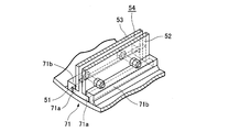
- the axial direction slide mechanism 71 in place of the adjusting bolt 55a and the elongated hole 55b, the axial direction slide mechanism 71 is replaced with a protruding portion (guided portion) 71a and a guide rail (guide portion) 71b for guiding it. It is composed of. That is, the partition wall base 51 is fixed to the main and sub partition plates 52 and 53 via connection means (bolts / nuts) or welding, and the gap 54 is held by the partition base 51 to connect the partition wall base 51 to the shell body. Separate from 20B.
- a pair of protruding portions (guided portions) 71a are integrally formed on both sides of the bottom of the partition wall substrate 51 in parallel with the container axis O, and both protruding portions 71a are slidably guided to the shell body 20B. It is comprised by fixing the guide rail (guide part) 71b to do.
- the axial direction slide mechanism 72 is integrally formed on the outer surface of the edge of the main and sub partition plates 52 and 53, and the protruding portion (guided portion) 72 a is integrated in parallel with the container axis O. Install. And the guide rail (guide part) 72b which guides both the protruding item
- the axial direction slide mechanisms 70 to 72 shown in FIGS. 7A to 7C can achieve the same functions and effects as the previous embodiments.
- the sub partition plate 53 is arranged corresponding to the arrangement part of the unit assembly 41, and the catalyst unit 24 is attached thereto.
- a movable seal portion 56 for preventing the exhaust gas from blowing through the gap 54 between the sub partition plate 53 and the main partition plate 52 is provided. It has been.
- the movable seal portion 56 can seal the exhaust gas following the displacement of the sub partition plate 53 in the container axis O direction and in the direction along the cross section of the container.
- the movable seal portion 56 has a fixed end attached to the main partition plate 52 via the mounting screw 56 b, and a free end side that is in sliding contact with the end portion of the sub partition plate 53.
- the elastic seal plate 56a is provided.
- the free end side of the elastic seal plate 56 a has a curved cross section and is pressed against the end of the sub partition plate 53. Therefore, even if the sub partition plate 53 moves with respect to the main partition plate 52 within the range of the displacement ⁇ in the container axis O direction and the displacement ⁇ in the direction along the cross section of the container, the elasticity follows the displacement.
- the sealing portion of the gap 54 can be maintained by being brought into sliding contact with the end portion of the sub partition plate 53.
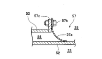
- a movable seal portion 57 shown in FIG. 9 may be provided. That is, the fixed end of the elastic seal plate 57a is attached to the end plate 57c of the sub partition plate 53 via the mounting screw 57b, and the free end side of the elastic seal plate 57a is brought into sliding contact with the surface of the main partition plate 52. Thereby, the sealing state of the gap 54 can be maintained.
- Example 1 (How to use Example 1)
- the exhaust gas switching valve 17 is closed to close the bypass pipe 16 and the denitration outlet valve 15 is opened to open the denitration gas discharge pipe 14.
- the evaporation chamber outlet valve 33 is opened to allow the evaporation chamber 23 and the reaction chamber 25 to communicate with each other.
- the exhaust gas discharged from the combustion chamber of the diesel engine 13 is introduced into the evaporation chamber 23 of the denitration reaction vessel 11 and mixed. Further, urea water (or ammonia water) is blown into the exhaust gas in the evaporation chamber 23 from the spray nozzle 22.
- the exhaust gas into which urea water has been blown is introduced into the reaction chamber 25 from the evaporation chamber 23 through the evaporation chamber outlet valve 33 and the intermediate passage 32.
- the exhaust gas passes through the catalyst unit 24 and comes into contact with the catalyst element 43, whereby NOx in the exhaust gas is reduced.
- the denitration exhaust gas is introduced from the denitration gas outlet 28 through the denitration gas discharge pipe 14 into the intake port 12i of the turbine section 12T of the exhaust gas supercharger 12, and the exhaust gas supercharger 12 is driven. Thereafter, the denitration exhaust gas is discharged from the exhaust port 12o through the exhaust chimney.
- combustion air atmosphere
- both the constituent members of the evaporation chamber 23 and the constituent members of the reaction chamber are exposed to high-temperature exhaust gas, so that they thermally expand to the same extent, compared to when they are stopped (cold temperature). There is little change.
- the injection of urea water from the spray nozzle 22 is stopped, the exhaust gas switching valve 17 is opened, and the bypass pipe 16 is communicated. Further, the denitration outlet valve 15 is closed to close the denitration gas discharge pipe 14, and the evaporation chamber outlet valve 33 is closed to shut off the evaporation chamber 23 and the reaction chamber 25.
- the exhaust gas discharged from the combustion chamber of the diesel engine 13 is introduced and mixed into the evaporation chamber 23 of the denitration reaction vessel 11, it is introduced from the bypass pipe 16 to the intake port 12i of the turbine section 12T. After the exhaust gas supercharger 12 is driven, the exhaust gas is discharged from the exhaust port 12o through the exhaust chimney.
- the evaporation chamber 23 into which the exhaust gas is introduced becomes high temperature, and the reaction chamber 25 becomes low temperature. Due to this temperature difference, the main partition plate 52 of the partition wall 21 is thermally expanded, and the sub partition plate 53 is not thermally expanded as much as the main partition plate 52.
- the partition wall 21 has a double wall structure having the gap 54, the thermal expansion difference in the cross-sectional direction of the denitration reaction vessel 11 is absorbed. Further, the difference in thermal expansion in the container axis O direction is absorbed by the axial direction slide mechanism, and the denitration reaction vessel 11 is not damaged by thermal strain.
- the partition wall The double wall structure of 21 can absorb the expansion / contraction difference in the direction along the transverse section of the container due to thermal expansion. Further, the axial direction sliding mechanism 55 of the partition wall 21 absorbs a difference in expansion and contraction due to thermal expansion in the direction of the container axis O, and the structural members such as the partition wall 21 of the denitration reaction container 11 due to thermal strain are damaged. Can be prevented.
- the axial center direction sliding mechanism 55 is constituted by an elongated hole 55b which is a guide portion and an adjustment bolt 55a which is a guided portion which is slidably engaged with the elongated hole 55b. Expansion and contraction due to the difference in thermal expansion in the direction can be effectively absorbed.
- the movable seal portion 56 made of the elastic seal plate 56 a is provided at the opening ends of the main partition plate 52 and the sub partition plate 53, the sub partition plate 53 is displaced with respect to the main partition plate 52. Also, the elastic seal plate 56a follows and is slidably contacted with the sub partition plate 53. As a result, the gap between the main partition plate 52 and the sub partition plate 53 can be reliably sealed, and the exhaust gas can be prevented from being blown through the gap 54 of the partition wall 21.
- Example 2 of the container body 20 will be described with reference to FIG.
- the same members as those in the previous embodiment are denoted by the same reference numerals, and description thereof is omitted.
- this container body 80 The purpose of this container body 80 is to bring the evaporation chamber 83 close to a circular cross section where exhaust gas and urea water (or ammonia water) can be mixed efficiently. That is, the partition wall 81 that divides the evaporation chamber 83 and the reaction chamber 85 is formed in a double wall structure including the main partition plate 52 and the sub partition plate 53 arranged with the gap 54 interposed therebetween. Further, the partition wall 81 has inclined wall portions 81Vg and 81Hg inclined to the reaction chamber 25 side at intermediate ends of the outer peripheral vertical wall portion 81Vo and the outer peripheral horizontal wall portion 81Ho suspended from the shell 80B. The intermediate vertical wall portion 81Vm and the intermediate horizontal wall portion 81Hm are formed.
- the cross-sectional area of the evaporation chamber 83 is expanded to the reaction chamber 85 side. Further, a chamfered inclined wall portion 81C for removing the corner portion is formed at the corner portion of the intermediate vertical wall portion 81Vm and the intermediate horizontal wall portion 81Hm.
- the double wall structure of the partition wall 81, the axial direction slide mechanism 55, and the movable seal portion 56 are similarly configured.
- the evaporation chamber 83 expanded so as to approach a substantially circular cross section, the corner portion that becomes a gas reservoir is eliminated, and the exhaust gas in the evaporation chamber 83 is removed.
- the mixing state of urea water or ammonia water and exhaust gas can be improved.
Landscapes
- Engineering & Computer Science (AREA)
- Chemical & Material Sciences (AREA)
- Combustion & Propulsion (AREA)
- Chemical Kinetics & Catalysis (AREA)
- Mechanical Engineering (AREA)
- General Engineering & Computer Science (AREA)
- Health & Medical Sciences (AREA)
- Toxicology (AREA)
- Ocean & Marine Engineering (AREA)
- Biomedical Technology (AREA)
- Environmental & Geological Engineering (AREA)
- Analytical Chemistry (AREA)
- General Chemical & Material Sciences (AREA)
- Oil, Petroleum & Natural Gas (AREA)
- Exhaust Gas After Treatment (AREA)
- Exhaust Gas Treatment By Means Of Catalyst (AREA)
Description
本発明は、船舶に搭載されたディーゼルエンジンから排出される排ガス中に尿素水やアンモニア水を吹き込む蒸発室と、排ガスと接触させて窒素酸化物を除去する触媒ユニットを有する反応室とを具備した船舶用排ガス脱硝反応容器およびこの脱硝反応容器を具備した船舶用排ガス脱硝設備に関する。
に関する。
に関する。
内燃機関から排出される排ガス中の窒素酸化物(以下、NOxという)を除去するために接触還元(SCR)による脱硝装置では、還元剤として、尿素水を使用するものが特許文献1などに提案されている。
船舶では、大型のディーゼルエンジンを搭載している。このディーゼルエンジンから排出される排ガス処理のために、限られた空間の有効利用を目的として、排ガス中に脱硝用還元剤である尿素水やアンモニア水を吹き込む蒸発室と、NOxを除去する脱硝触媒の触媒エレメントを配置した反応室とを、1つの反応容器に設置した脱硝反応器が考えられる。
ところで、一部の海域(NOx規制海域)では、船舶のディーゼルエンジンから排出される排ガス中の窒素酸化物を、現行の規定から大幅に削減する規定を実施する動きがある。こうしたNOx規制海域と、窒素酸化物の削減の規定のないNOx非規制海域とを航行する場合、NOx非規制海域では、排ガスを反応室に導入する必要がない。このため、先に述べたように、蒸発室と反応室とを一つの反応容器に設置した場合、蒸発室と反応室の温度差による熱膨張差から発生する熱歪みにより、反応容器の構成部材が損傷される恐れがあった。
本発明は、蒸発室と反応室とを一体に設けた脱硝反応器内において、蒸発室と反応室における温度差による熱膨張差を効果的に吸収して、熱歪みによる損傷を防止できる船舶用排ガス脱硝反応容器およびこの脱硝反応容器を具備した船舶用排ガス脱硝設備を提供することを目的とする。
請求項1記載の発明は、
筒状に形成された反応容器内に、排ガス中に尿素水またはアンモニア水を吹き込む蒸発室と、尿素水またはアンモニア水が吹き込まれた排ガスを接触させる触媒ユニットを設置した反応室とを設けた船舶用排ガス脱硝反応容器であって、
前記反応容器の容器本体内に、前記蒸発室と前記反応室と区画する隔壁を、容器軸心方向に沿って設けるとともに、前記蒸発器に未処理ガス出口を設け、
前記隔壁を、容器軸心および前記反応容器の横断面に沿う方向に伸縮して前記蒸発室と前記反応室の構成部材の熱膨張差を吸収できる熱膨張吸収構造とし、
当該熱膨張吸収構造は、
前記容器本体の胴殻体内面で容器軸心方向に沿う隔壁基材に、前記蒸発室側に取り付けられた主仕切り板と、前記反応室側に取り付けられて前記主仕切り板との間に一定隙間をあけて配置されたかつ前記触媒ユニットが取り付けられた副仕切り板と、からなる二重壁構造とするとともに、前記隔壁基材と前記主仕切り板および前記副仕切り板との間に、容器軸心方向に所定範囲で移動自在な軸心方向スライド機構を具備し、さらに、前記副仕切り板の排ガス流送方向の前後端部で、前記副仕切り板と前記主仕切り板との間に、前記副仕切り板および前記主仕切り板の容器軸心方向および前記反応容器の横断面に沿う方向の熱膨張による変位に追従可能な可動シール部を設けたことを特徴とする。
筒状に形成された反応容器内に、排ガス中に尿素水またはアンモニア水を吹き込む蒸発室と、尿素水またはアンモニア水が吹き込まれた排ガスを接触させる触媒ユニットを設置した反応室とを設けた船舶用排ガス脱硝反応容器であって、
前記反応容器の容器本体内に、前記蒸発室と前記反応室と区画する隔壁を、容器軸心方向に沿って設けるとともに、前記蒸発器に未処理ガス出口を設け、
前記隔壁を、容器軸心および前記反応容器の横断面に沿う方向に伸縮して前記蒸発室と前記反応室の構成部材の熱膨張差を吸収できる熱膨張吸収構造とし、
当該熱膨張吸収構造は、
前記容器本体の胴殻体内面で容器軸心方向に沿う隔壁基材に、前記蒸発室側に取り付けられた主仕切り板と、前記反応室側に取り付けられて前記主仕切り板との間に一定隙間をあけて配置されたかつ前記触媒ユニットが取り付けられた副仕切り板と、からなる二重壁構造とするとともに、前記隔壁基材と前記主仕切り板および前記副仕切り板との間に、容器軸心方向に所定範囲で移動自在な軸心方向スライド機構を具備し、さらに、前記副仕切り板の排ガス流送方向の前後端部で、前記副仕切り板と前記主仕切り板との間に、前記副仕切り板および前記主仕切り板の容器軸心方向および前記反応容器の横断面に沿う方向の熱膨張による変位に追従可能な可動シール部を設けたことを特徴とする。
請求項2記載の発明は、請求項1の構成において、
前記軸心方向スライド機構は、前記主仕切り板および前記副仕切り板と、前記隔壁基材の一方に容器軸心方向に形成されたガイド部と、他方に形成されて前記ガイド部にスライド自在に係合される被ガイド部材とを具備したことを特徴とする。
前記軸心方向スライド機構は、前記主仕切り板および前記副仕切り板と、前記隔壁基材の一方に容器軸心方向に形成されたガイド部と、他方に形成されて前記ガイド部にスライド自在に係合される被ガイド部材とを具備したことを特徴とする。
請求項3記載の発明は、請求項1または2記載の構成において、
前記可動シール部は、固定端が前記主仕切り板および前記副仕切り板の一方の端部に取り付けられて、遊端側が他方に摺接される弾性シール板を備えたことを特徴とする。
前記可動シール部は、固定端が前記主仕切り板および前記副仕切り板の一方の端部に取り付けられて、遊端側が他方に摺接される弾性シール板を備えたことを特徴とする。
請求項4記載の発明は、
請求項1乃至3のいずれかに記載の船舶用排ガス脱硝反応容器と、
前記反応室から脱硝ガス排出管を介して排ガスを給気口に供給する排ガス過給機と、
当該排ガス過給機の給気口と前記蒸発室の未処理ガス出口とを接続するバイパス管と、
当該バイパス管を開閉可能な排ガス切換弁と、
少なくとも前記脱硝ガス排出管に介在されて当該脱硝ガス排出管を開閉可能なガス遮断弁と、を具備し、
前記蒸発室を、複数のディーゼルエンジンから排出される排ガスを合流して前記排ガス過給機に排ガスを給気するマニホールドに兼用したことを特徴とする。
請求項1乃至3のいずれかに記載の船舶用排ガス脱硝反応容器と、
前記反応室から脱硝ガス排出管を介して排ガスを給気口に供給する排ガス過給機と、
当該排ガス過給機の給気口と前記蒸発室の未処理ガス出口とを接続するバイパス管と、
当該バイパス管を開閉可能な排ガス切換弁と、
少なくとも前記脱硝ガス排出管に介在されて当該脱硝ガス排出管を開閉可能なガス遮断弁と、を具備し、
前記蒸発室を、複数のディーゼルエンジンから排出される排ガスを合流して前記排ガス過給機に排ガスを給気するマニホールドに兼用したことを特徴とする。
請求項1記載の発明によれば、反応容器内に、隔壁により区画された蒸発室と反応室とを一体に設ける。そして前記隔壁の熱膨張吸収構造に、主仕切り板と副仕切り板とを一定の隙間を開けて配置した二重壁構造とすることにより、容器の横断面に沿う方向の伸縮を吸収する。また隔壁基材と主仕切り板および副仕切り板の取り付け部に設けた軸心方向スライド機構により、容器軸方向の伸縮を吸収する。
したがって、蒸発室の排ガスを未処理排ガス出口から排出することにより、反応室に排ガスを導入しない非脱硝処理時に、蒸発室が高温の状態となり、反応室が低温の状態となることがあっても、隔壁の熱膨張吸収構造により、伸縮を効果的に吸収することができ、反応容器の構成部材に熱歪みによる損傷が生じるのを未然に防止することができる。
請求項2記載の発明によれば、軸心方向スライド機構を、ガイド部とこのガイド部にスライド自在に係合される被ガイド部で構成することにより、主仕切り板と副仕切り板の熱膨張差による軸心方向の伸縮を効果的に吸収することができる。
請求項3記載の発明によれば、副仕切り板の前後端部で、副仕切り板と主仕切り板との間に弾性シール板を設けたので、副仕切り板および主仕切り板における容器軸心方向および容器の横断面に沿う方向の熱膨張による変位に対応して、弾性シール板が変形され、副仕切り板または主仕切り板の変位に追従させることができ、主仕切り板と副仕切り板の隙間を確実にシールすることができて、排ガスの吹き抜けを確実に防止することができる。
請求項4記載の発明によれば、NOx非規制海域などで排ガスを脱硝処理しない時に、排ガス切換弁を開放してバイパス管を連通するとともに、ガス遮断弁を閉鎖して連通部や脱硝ガス排出管を遮断する。これにより、複数のディーゼルエンジンから排出されて蒸発室で合流された排ガスを、蒸発室の未処理排ガス口からバイパス管を介して排ガス過給機に導入することができる。この場合、排ガスが導入される蒸発室と、排ガスが導入されない反応室との間に温度差が生じる。この温度差により、隔壁の主仕切り板と副仕切り板とに熱膨張による伸縮差が発生する。しかし、隔壁の熱膨張吸収構造の一部である二重壁構造により、隔壁の容器の横断面に沿う方向の伸縮差を吸収することができる。また、隔壁の熱膨張吸収構造の残部である軸心方向スライド機構により容器軸方向の伸縮差を吸収することができる。したがって、蒸発室と反応室との温度差による熱歪みを効果的に吸収できて、反応容器の構成部材が熱歪みにより損傷されるのを未然に防止することができる。
[実施例1]
以下、本発明の実施例1を図1~図12に基づいて説明する。
以下、本発明の実施例1を図1~図12に基づいて説明する。
(船舶用排ガス脱硝設備)
図1は、本発明に係る船舶用ディーゼルエンジン13の燃焼室から排出される排ガスを脱硝処理するための船舶用排ガス脱硝設備を示す構成図である。図中、11は脱硝反応容器(反応容器)、12はディーゼルエンジン13の排ガスにより駆動される排ガス過給機である。脱硝反応容器11の容器本体20に、容器軸心O方向に沿う隔壁21が設置されており、容器本体20内に蒸発室23と反応室25が一体に収容されている。すなわち、前記隔壁21の下部に、排ガス中に尿素水(又はアンモニア水)を吹き込む蒸発室23が形成され、隔壁21の上部に尿素水が吹き込まれた排ガスを複数の触媒ユニット24に接触させてNOxを還元する反応室25が形成されている。
図1は、本発明に係る船舶用ディーゼルエンジン13の燃焼室から排出される排ガスを脱硝処理するための船舶用排ガス脱硝設備を示す構成図である。図中、11は脱硝反応容器(反応容器)、12はディーゼルエンジン13の排ガスにより駆動される排ガス過給機である。脱硝反応容器11の容器本体20に、容器軸心O方向に沿う隔壁21が設置されており、容器本体20内に蒸発室23と反応室25が一体に収容されている。すなわち、前記隔壁21の下部に、排ガス中に尿素水(又はアンモニア水)を吹き込む蒸発室23が形成され、隔壁21の上部に尿素水が吹き込まれた排ガスを複数の触媒ユニット24に接触させてNOxを還元する反応室25が形成されている。
脱硝反応容器11の容器本体20は、たとえば円筒状の胴殻体20Bの両端部が湾曲凸状の耐圧用端板20R,20Lにより閉鎖された耐圧容器に形成されている。前記胴殻体20Bの底部に、蒸発室23に排ガスを導入する複数の排ガス入口26が形成されている。そして、ディーゼルエンジン13の複数(図は4室)の燃焼室から排出される排ガスが、前記排ガス入口26を介して蒸発室にそれぞれ導入される。また、この蒸発室23が、複数の排ガス入口26から導入された排ガスを合流させる排ガスマニホールドに兼用されている。さらに、胴殻体20Bの一方の端板20Lの下部近傍に、蒸発室23に連通される未処理ガス出口27が形成されている。さらにまた、胴殻体20Bの一方の端板20Lの上部近傍に、反応室25に連通されて脱硝排ガスを排出する脱硝ガス出口28が形成されている。
排ガス過給機12は、入出力軸により互いに連結されたタービン部12Tとコンプレッサ部12Cとを具備している。タービン部12Tでは、ディーゼルエンジン13の燃焼室から脱硝反応容器11を介して排出された未処理排ガスまたは脱硝排ガスが給気口12iに供給される。タービン部12Tの排気口12oから放出された排ガスが排気煙突から排出される。またコンプレッサ部12Cでは、吸気口から大気を吸引して加圧し、加圧された空気を、燃焼用空気として排気口からディーゼルエンジン13の燃焼室に供給する。
排ガス過給機12は、入出力軸により互いに連結されたタービン部12Tとコンプレッサ部12Cとを具備している。タービン部12Tでは、ディーゼルエンジン13の燃焼室から脱硝反応容器11を介して排出された未処理排ガスまたは脱硝排ガスが給気口12iに供給される。タービン部12Tの排気口12oから放出された排ガスが排気煙突から排出される。またコンプレッサ部12Cでは、吸気口から大気を吸引して加圧し、加圧された空気を、燃焼用空気として排気口からディーゼルエンジン13の燃焼室に供給する。
脱硝反応容器11の脱硝ガス出口28とタービン部12Tの給気口12iとの間に、脱硝ガス排出管14が接続されている。この脱硝ガス排出管14の給気口12i近傍に、脱硝反応容器11の未処理ガス出口27に接続されたバイパス管16が接続されている。そしてこの脱硝ガス排出管14とバイパス管16の接続部の上流側で脱硝ガス排出管14に、バタフライ弁からなる脱硝出口弁(ガス遮断弁)15が設けられている。この脱硝出口弁15により、脱硝ガス排出管14を閉鎖可能に構成している。またバイパス管16に、バイパス管16を開閉可能なバタフライ弁からなる排ガス切換弁17が設けられている。
(脱硝反応容器)
容器本体20の一方の端板20Lには、蒸発室23の排ガス中に尿素水またはアンモニア水を吹き込むスプレーノズル22が配置されている。また容器本体20の他方の端板20R側に連通部30が形成されている。この連通部30は、隔壁21と蒸発室23の胴殻体20Bとの間で、反応容器11の横断面に沿って配置され蒸発室23を閉鎖する区画壁31と、隔壁21(区画壁31)と他方の端板20Rとの間に形成された中間通路32と、この区画壁31の開口部に設けられた蒸発室出口弁(ガス遮断弁)33と、区画壁31に形成されて蒸発室23と反応室25とを等圧に調整するための単数または複数の調圧口34とで構成されている。
容器本体20の一方の端板20Lには、蒸発室23の排ガス中に尿素水またはアンモニア水を吹き込むスプレーノズル22が配置されている。また容器本体20の他方の端板20R側に連通部30が形成されている。この連通部30は、隔壁21と蒸発室23の胴殻体20Bとの間で、反応容器11の横断面に沿って配置され蒸発室23を閉鎖する区画壁31と、隔壁21(区画壁31)と他方の端板20Rとの間に形成された中間通路32と、この区画壁31の開口部に設けられた蒸発室出口弁(ガス遮断弁)33と、区画壁31に形成されて蒸発室23と反応室25とを等圧に調整するための単数または複数の調圧口34とで構成されている。
なお、ここで蒸発室出口弁33を削除して開口部を開放した状態で、脱硝ガス排出管14の脱硝出口弁15を閉鎖することにより、反応室25や脱硝ガス排出管14の通気抵抗を利用して、すべての排ガスを蒸発室23から排ガス過給機12のタービン部12Tに導入することができる。この場合、蒸発室23と反応室25との間に圧力差が生じないため、調圧口34を形成する必要がない。
(反応室)
図3,図4に示すように、反応室25にユニット集合体41が設置されている。このユニット集合体41は、隔壁21と胴殻体20Bの間に、複数の触媒ユニット24が上下、左右方向に積み重ねて配置され、かつ容器軸心O方向に連結されている。これら触媒ユニット24は、たとえば図5に示すように、対抗する側面に切り欠き穴42aが形成された収納枠体42と、収納枠体42内に収容されたハニカム状断面の触媒エレメント43とを具備したものある。これらユニット集合体41の断面形態として、図13に示す長方形断面や台形断面のものが採用される。
図3,図4に示すように、反応室25にユニット集合体41が設置されている。このユニット集合体41は、隔壁21と胴殻体20Bの間に、複数の触媒ユニット24が上下、左右方向に積み重ねて配置され、かつ容器軸心O方向に連結されている。これら触媒ユニット24は、たとえば図5に示すように、対抗する側面に切り欠き穴42aが形成された収納枠体42と、収納枠体42内に収容されたハニカム状断面の触媒エレメント43とを具備したものある。これらユニット集合体41の断面形態として、図13に示す長方形断面や台形断面のものが採用される。
このユニット集合体41は、胴殻体20B内で、胴殻体20Bとユニット集合体41との間隔を調整する複数の外周支持具44を介して支持されている。また、反応室25の一端側(排ガス流の下流側)に、固定具45と、胴殻体20Bとユニット集合体41との空間を閉鎖する外周閉鎖板46が配置されている。また、反応室25の他端側(排ガス流の上流側)に押さえ具47が配置されている。これら外周支持具44や固定具45、外周閉鎖板46、押さえ具47により、ユニット集合体41が胴殻体20B内に保持されている。なお、図4に示すA-A断面矢視線は、図3の断面位置を示している。
外周支持具44は、図10に示すように、容器軸心Oに平行な軸心に対して所定角度傾斜する傾斜面で切断されかつ傾斜面で摺動可能な一対のテーパスリーブ44a,44bを有している。これらテーパスリーブ44a,44bのうち、一方のテーパスリーブ44aが触媒ユニット24の収納枠体42に取り付けられている。また他方のテーパスリーブ44bが連結部材44cを介して胴殻体20Bに取り付けられている。そしてテーパスリーブ44a,44bの軸穴44e,44fに連結ボルト・ナット44dが遊嵌され、連結ボルト・ナット44dによりテーパスリーブ44a,44bのスライド限が規制されている。そして、連結ボルト・ナット44dによるテーパスリーブ44a,44bのスライド範囲で、胴殻体20Bとユニット集合体41の熱膨張による容器軸心O方向の伸縮差を吸収することができる。そして、これら外周支持具44により、胴殻体20Bと隔壁21との間でユニット集合体41の外周部分が支持される。
ユニット集合体41の排ガス流の下流端に設置される固定具45は、図11の右部および図12に示すように、触媒ユニット24の配置パターン(図3)に対応する略格子状の板状枠体45aを具備している。この板状枠体45aは、面取りされた前端部が、隣接する触媒ユニット24同士の接触部に当接される。そして、取付部材45bにより、板状枠体45aの外周端部が胴殻体20Bにそれぞれ連結固定され、ユニット集合体41が排ガスの下流側に移動するのを規制している。外周閉鎖板46は、取付部材45bの下流側に設置されて排ガスを遮蔽している。なお、板状枠体45aの外縁部は、半割の断面形状に形成されている。
ユニット集合体41の排ガス流の上流端に設置される押さえ具47は、図11の左部に示すように、触媒ユニット24の配置パターン(図3)に対応する一体の略格子状の線状枠体47aを具備している。この線状枠体47aは、円形断面のロッド状に形成され、隣接する触媒ユニット24同士の接触部前面に形成されるテーパ溝に嵌合される。そして、胴殻体20Bに立設されたブラケット47bに、容器軸心O方向の押さえボルト47cが嵌合されている。そして、押さえボルト47cは、ロックナット47dにより加圧状態で固定され、押さえボルト47cの先端部が、押さえ板47eを介して線状枠体47aが触媒ユニット24に押し付けられている。この押さえ具47により、ユニット集合体41が固定具45との間で容器軸心O方向に位置決め固定されている。なお、上記実施例1では、略格子状の線状枠体47aを一体構造としたが、線状枠体47aを縦横断面に沿って複数に分割された分割構造とし、組み立てて使用してもよい。
(容器本体1)
図3に示すように、この容器本体20内で胴殻体20B内に設置される隔壁21が、略容器軸心O近傍をコーナー部としてL形に連結された鉛直壁部21Vと水平壁部21Hからなり、隔壁21で区画された図右下の略1/4が蒸発室23に、残部3/4が反応室25にそれぞれ形成されている。ここで、容器本体20を円筒形に形成しているが、四角筒や五角形以上の多角筒形などの筒形であってもよい。
図3に示すように、この容器本体20内で胴殻体20B内に設置される隔壁21が、略容器軸心O近傍をコーナー部としてL形に連結された鉛直壁部21Vと水平壁部21Hからなり、隔壁21で区画された図右下の略1/4が蒸発室23に、残部3/4が反応室25にそれぞれ形成されている。ここで、容器本体20を円筒形に形成しているが、四角筒や五角形以上の多角筒形などの筒形であってもよい。
この隔壁21は、容器軸心Oおよび容器の横断面に沿う方向に伸縮して、蒸発室23と反応室25との温度差による構成部材の熱膨張差を吸収できる熱膨張吸収構造に構成されている。
すなわち、隔壁21は、胴殻体20Bの内面に隔壁基材51が容器軸心O方向に沿って取り付けられている。そして、これら隔壁基材51に、蒸発室側に取り付けられた主仕切り板52と、隔壁基材51の反応室25側で、主仕切り板52との間に一定の隙間54をあけて取り付けられた副仕切り板53が設けられ、主仕切り板52と副仕切り板53からなる二重壁構造に形成されている。この二重壁構造は、隔壁基材51により一定の隙間54が保持されて、主、副仕切り板52,53の容器の横断面に沿う方向の熱膨張(差)を吸収することができる。そして、隔壁基材51と、これら主仕切り板52および副仕切り板53との間に、容器軸心O方向の熱膨張を所定範囲で吸収可能な軸心方向スライド機構55が設けられている。すなわち、この軸心方向スライド機構55は、図6に示すように、たとえば隔壁基材51に容器軸心O方向に一定間隔ごとに複数の調整ボルト(被ガイド部)55aが容器接線方向に貫設されている。そして、主、副仕切り板52,53に調整ボルト55aがそれぞれスライド自在に嵌合される長穴(ガイド部)55bが容器軸心Oに平行に形成されている。したがって、これら調整ボルト55aと長穴55bとにより、主、副仕切り板52,53における容器軸心O方向の熱膨張(差)を吸収することができる。そして、これら二重壁構造と軸心方向スライド機構55とで熱膨張吸収構造が構成されている。
なお、ここで軸心方向スライド機構55の変形例1~3を、図7A~図7Cを参照して説明する。
図7Aに示す変形例1は、軸心方向スライド機構70を、調整ボルト(被ガイド部)55aを、主、副仕切り板52,53に固定し、長穴(ガイド部)55bを隔壁基材51に設けたものである。
また図7Bに示す変形例2は、調整ボルト55aおよび長穴55bに替えて、軸心方向スライド機構71を、突条部(被ガイド部)71aとこれを案内するガイドレール(ガイド部)71bとで構成したものである。すなわち、隔壁基材51に、連結具(ボルト・ナット)や溶接などの連結手段を介して主、副仕切り板52,53が固定されて隙間54を保持させ、隔壁基材51を胴殻体20Bから分離する。そして、隔壁基材51の底部両側に一対の突条部(被ガイド部)71aを容器軸心Oに平行に一体形成し、胴殻体20Bに、両突条部71aをそれぞれスライド自在に案内するガイドレール(ガイド部)71bを固定することにより構成される。
また図7Cに示す変形例3は、軸心方向スライド機構72を、主、副仕切り板52,53の縁部外面に突条部(被ガイド部)72aを容器軸心Oに平行に一体に取り付ける。そして胴殻体20Bに、両突条部72aをそれぞれスライド自在に案内するガイドレール(ガイド部)72bを固定したものである。
このように、図7A~図7Cに示す軸心方向スライド機構70~72変形例1~3は、先の実施例と同様の作用効果を奏することができる。
また、副仕切り板53は、ユニット集合体41の配置部位に対応して配置されており、触媒ユニット24が取り付けられている。この副仕切り板53の排ガスの上流側(他端側)および下流側(一端側)に、副仕切り板53と主仕切り板52との隙間54における排ガスの吹き抜けを防止する可動シール部56が設けられている。この可動シール部56は、副仕切り板53の容器軸心O方向および容器の横断面に沿う方向の変位に追従して排ガスをシールすることができる。
すなわち、図8に示すように、この可動シール部56は、固定端が主仕切り板52に取付ビス56bを介して取り付けられ、遊端側が副仕切り板53の端部に摺接される耐熱性の弾性シール板56aが設けられている。この弾性シール板56aの遊端側が湾曲状断面となって副仕切り板53の端部に圧接される。したがって、主仕切り板52に対して副仕切り板53が容器軸心O方向の変位βおよび容器の横断面に沿う方向に変位γの範囲で移動しても、その弾性により、変位に追従して副仕切り板53の端部に摺接され、隙間54のシール状態を維持することができる。
また、図9に示す可動シール部57を設けてもよい。すなわち、弾性シール板57aの固定端を副仕切り板53の端板57cに取付ビス57bを介して取り付け、弾性シール板57aの遊端側を主仕切り板52の表面に摺接させる。これにより、隙間54のシール状態を維持することができる。
(実施例1の使用方法)
上記構成において、NOx規制海域を航行する時には、排ガス切換弁17を閉鎖操作してバイパス管16を閉じ、脱硝出口弁15を開放操作して脱硝ガス排出管14を開放する。これにより蒸発室出口弁33を開放操作して蒸発室23と反応室25とを連通する。そして、ディーゼルエンジン13の燃焼室からそれぞれ排出される排ガスを脱硝反応容器11の蒸発室23に導入し混合する。さらにスプレーノズル22から尿素水(又はアンモニア水)を蒸発室23の排ガス中に吹き込む。そして尿素水が吹き込まれた排ガスを、蒸発室23から蒸発室出口弁33、中間通路32を介して反応室25に導入する。排ガスが触媒ユニット24を通過して触媒エレメント43に接触されることにより、排ガス中のNOxが還元される。次いで、脱硝排ガスが脱硝ガス出口28から脱硝ガス排出管14を介して排ガス過給機12のタービン部12Tの給気口12iに導入されて、排ガス過給機12を駆動する。その後、脱硝排ガスは排気口12oから排気煙突を介して排出される。排ガス過給機12のコンプレッサ部12Cでは、燃焼用空気(大気)を吸引して圧縮し、ディーゼルエンジン13の燃焼室に供給する。
上記構成において、NOx規制海域を航行する時には、排ガス切換弁17を閉鎖操作してバイパス管16を閉じ、脱硝出口弁15を開放操作して脱硝ガス排出管14を開放する。これにより蒸発室出口弁33を開放操作して蒸発室23と反応室25とを連通する。そして、ディーゼルエンジン13の燃焼室からそれぞれ排出される排ガスを脱硝反応容器11の蒸発室23に導入し混合する。さらにスプレーノズル22から尿素水(又はアンモニア水)を蒸発室23の排ガス中に吹き込む。そして尿素水が吹き込まれた排ガスを、蒸発室23から蒸発室出口弁33、中間通路32を介して反応室25に導入する。排ガスが触媒ユニット24を通過して触媒エレメント43に接触されることにより、排ガス中のNOxが還元される。次いで、脱硝排ガスが脱硝ガス出口28から脱硝ガス排出管14を介して排ガス過給機12のタービン部12Tの給気口12iに導入されて、排ガス過給機12を駆動する。その後、脱硝排ガスは排気口12oから排気煙突を介して排出される。排ガス過給機12のコンプレッサ部12Cでは、燃焼用空気(大気)を吸引して圧縮し、ディーゼルエンジン13の燃焼室に供給する。
このように、排ガス脱硝設備の運転時には、蒸発室23の構成部材も、反応室の構成部材も、それぞれ高温の排ガスに晒されることから同程度に熱膨張し、停止(冷温)時に比較して変化は少ない。
次いでNOx非規制海域を航行する時には、図2に示すように、スプレーノズル22からの尿素水の噴射を停止するとともに、排ガス切換弁17を開放しバイパス管16を連通する。さらに脱硝出口弁15を閉鎖して脱硝ガス排出管14を閉じ、蒸発室出口弁33を閉鎖して蒸発室23と反応室25とを遮断する。これにより、ディーゼルエンジン13の燃焼室からそれぞれ排出される排ガスが、脱硝反応容器11の蒸発室23に導入されて混合された後、バイパス管16からタービン部12Tの給気口12iに導入され、排ガス過給機12を駆動した後、排気口12oから排気煙突を介して排出される。
この時、反応室25に高温の排ガスが導入されないため、排ガスが導入される蒸発室23は高温になり、反応室25は低温となる。この温度差により、隔壁21の主仕切り板52が熱膨張し、副仕切り板53が主仕切り板52ほど熱膨張しない。しかし、隔壁21が隙間54を有する二重壁構造であるため、脱硝反応容器11の横断面方向の熱膨張差が吸収される。また軸心方向スライド機構により、容器軸心O方向の熱膨張差が吸収され、熱歪みにより脱硝反応容器11が破損されることがない。
(実施例1の効果)
上記実施例1によれば、排ガスを脱硝処理しなくてもよいNOx非規制海域では、排ガス切換弁17を開放してバイパス管16を連通し、蒸発室出口弁33および脱硝出口弁15を閉じて連通部30および脱硝ガス排出管14を閉鎖する。そして複数のディーゼルエンジン13の燃焼室から排出された排ガスを蒸発室23内で合流させ、尿素水(またはアンモニア水)を吹き込むことなく未処理排ガスをバイパス管16から排ガス過給機12のタービン部12Tに導入する。この時、排ガスが導入される蒸発室23と、排ガスが導入されない反応室25との温度差により、隔壁21の主仕切り板52と副仕切り板53とに熱膨張差が発生しても、隔壁21の二重壁構造により、熱膨張による容器の横断面に沿う方向の伸縮差を吸収することができる。さらに、隔壁21の軸心方向スライド機構55により、容器軸心O方向の熱膨張による伸縮差を吸収して、熱歪みによる脱硝反応容器11の隔壁21などの構成部材が損傷されるのを未然に防止することができる。
上記実施例1によれば、排ガスを脱硝処理しなくてもよいNOx非規制海域では、排ガス切換弁17を開放してバイパス管16を連通し、蒸発室出口弁33および脱硝出口弁15を閉じて連通部30および脱硝ガス排出管14を閉鎖する。そして複数のディーゼルエンジン13の燃焼室から排出された排ガスを蒸発室23内で合流させ、尿素水(またはアンモニア水)を吹き込むことなく未処理排ガスをバイパス管16から排ガス過給機12のタービン部12Tに導入する。この時、排ガスが導入される蒸発室23と、排ガスが導入されない反応室25との温度差により、隔壁21の主仕切り板52と副仕切り板53とに熱膨張差が発生しても、隔壁21の二重壁構造により、熱膨張による容器の横断面に沿う方向の伸縮差を吸収することができる。さらに、隔壁21の軸心方向スライド機構55により、容器軸心O方向の熱膨張による伸縮差を吸収して、熱歪みによる脱硝反応容器11の隔壁21などの構成部材が損傷されるのを未然に防止することができる。
また、軸心方向スライド機構55を、ガイド部である長穴55bと、この長穴55bにスライド自在に係合される被ガイド部である調整ボルト55aにより構成することにより、隔壁21の軸心方向の熱膨張差による伸縮を効果的に吸収することができる。
さらに、隔壁21では、主仕切り板52と副仕切り板53の開口端に、弾性シール板56aからなる可動シール部56を設けたので、主仕切り板52に対して副仕切り板53が変位しても、弾性シール板56aが追従して副仕切り板53に摺接される。これにより、主仕切り板52と副仕切り板53との隙間を確実にシールすることができ、隔壁21の隙間54による排ガスの吹き抜けを防止することができる。
(実施例2)
容器本体20の実施例2を、図13を参照して説明する。先の実施例と同一部材には同一符号を付して説明を省略する。
容器本体20の実施例2を、図13を参照して説明する。先の実施例と同一部材には同一符号を付して説明を省略する。
この容器本体80において、蒸発室83を、排ガスと尿素水(またはアンモニア水)を効率よく混合可能な円形断面に接近させることを目的としている。すなわち、蒸発室83と反応室85とを区画する隔壁81が、隙間54を介して配置された主仕切り板52と副仕切り板53からなる二重壁構造に形成される。さらにこの隔壁81は、胴殻体80Bに垂設された外周鉛直壁部81Voおよび外周水平壁部81Hoの中間端部に、それぞれ反応室25側に傾斜する傾斜壁部81Vg,81Hgを介在させて、中間鉛直壁部81Vmと中間水平壁部81Hmを形成している。これにより、蒸発室83の断面積を反応室85側に拡張している。さらに、中間鉛直壁部81Vmと中間水平壁部81Hmのコーナー部に、隅部を削除する面取り斜壁部81Cを形成している。なお、隔壁81の二重壁構造や軸心方向スライド機構55や可動シール部56も同様に構成される。
実施例2によれば、実施例1の作用効果に加えて、略円形断面に接近するように拡張した蒸発室83を形成することにより、ガス溜まりとなる隅部を無くし、蒸発室83における排ガスの滞留を低減して、尿素水またはアンモニア水と排ガスとの混合状態を改善することができる。
Claims (4)
- 筒状に形成された反応容器内に、排ガス中に尿素水またはアンモニア水を吹き込む蒸発室と、尿素水またはアンモニア水が吹き込まれた排ガスを接触させる触媒ユニットを設置した反応室とを設けた船舶用排ガス脱硝反応容器であって、
前記反応容器の容器本体内に、前記蒸発室と前記反応室と区画する隔壁を、容器軸心方向に沿って設けるとともに、前記蒸発器に未処理ガス出口を設け、
前記隔壁を、容器軸心および前記反応容器の横断面に沿う方向に伸縮して前記蒸発室と前記反応室の構成部材の熱膨張差を吸収できる熱膨張吸収構造とし、
当該熱膨張吸収構造は、
前記容器本体の胴殻体内面で容器軸心方向に沿う隔壁基材に、前記蒸発室側に取り付けられた主仕切り板と、前記反応室側に取り付けられて前記主仕切り板との間に一定隙間をあけて配置されたかつ前記触媒ユニットが取り付けられた副仕切り板と、からなる二重壁構造とするとともに、前記隔壁基材と前記主仕切り板および前記副仕切り板との間に、容器軸心方向に所定範囲で移動自在な軸心方向スライド機構を具備し、さらに、前記副仕切り板の排ガス流送方向の前後端部で、前記副仕切り板と前記主仕切り板との間に、前記副仕切り板および前記主仕切り板の容器軸心方向および前記反応容器の横断面に沿う方向の熱膨張による変位に追従可能な可動シール部を設けた
ことを特徴とする船舶用排ガス脱硝反応容器。 - 前記軸心方向スライド機構は、前記主仕切り板および前記副仕切り板と、前記隔壁基材の一方に容器軸心方向に形成されたガイド部と、他方に形成されて前記ガイド部にスライド自在に係合される被ガイド部材とを具備した
ことを特徴とする請求項1記載の船舶用排ガス脱硝反応容器。 - 前記可動シール部は、固定端が前記主仕切り板および前記副仕切り板の一方の端部に取り付けられて、遊端側が他方に摺接される弾性シール板を備えた
ことを特徴とする請求項1または2記載の船舶用排ガス脱硝反応容器。 - 請求項1乃至3のいずれかに記載の船舶用排ガス脱硝反応容器と、
前記反応室から脱硝ガス排出管を介して排ガスを給気口に供給する排ガス過給機と、
当該排ガス過給機の給気口と前記蒸発室の未処理ガス出口とを接続するバイパス管と、
当該バイパス管を開閉可能な排ガス切換弁と、
少なくとも前記脱硝ガス排出管に介在されて当該脱硝ガス排出管を開閉可能なガス遮断弁と、を具備し、
前記蒸発室を、複数のディーゼルエンジンから排出される排ガスを合流して前記排ガス過給機に排ガスを給気するマニホールドに兼用した
ことを特徴とする船舶用排ガス脱硝設備。
Priority Applications (2)
| Application Number | Priority Date | Filing Date | Title |
|---|---|---|---|
| CN201380007359.5A CN104081014B (zh) | 2012-03-02 | 2013-02-12 | 船舶用废气脱硝反应容器及船舶用脱硝设备 |
| KR1020147019263A KR101590333B1 (ko) | 2012-03-02 | 2013-02-12 | 선박용 배기가스 탈초반응용기 및 선박용 탈초설비 |
Applications Claiming Priority (2)
| Application Number | Priority Date | Filing Date | Title |
|---|---|---|---|
| JP2012046008A JP5295403B2 (ja) | 2012-03-02 | 2012-03-02 | 船舶用排ガス脱硝反応容器および排ガス脱硝設備 |
| JP2012-046008 | 2012-03-02 |
Publications (1)
| Publication Number | Publication Date |
|---|---|
| WO2013129089A1 true WO2013129089A1 (ja) | 2013-09-06 |
Family
ID=49082291
Family Applications (1)
| Application Number | Title | Priority Date | Filing Date |
|---|---|---|---|
| PCT/JP2013/053186 Ceased WO2013129089A1 (ja) | 2012-03-02 | 2013-02-12 | 船舶用排ガス脱硝反応容器および船舶用脱硝設備 |
Country Status (4)
| Country | Link |
|---|---|
| JP (1) | JP5295403B2 (ja) |
| KR (1) | KR101590333B1 (ja) |
| CN (1) | CN104081014B (ja) |
| WO (1) | WO2013129089A1 (ja) |
Cited By (4)
| Publication number | Priority date | Publication date | Assignee | Title |
|---|---|---|---|---|
| JP2013245677A (ja) * | 2012-05-24 | 2013-12-09 | Decco Ltd | 窒素酸化物除去装置および窒素酸化物除去方法 |
| EP2902601A4 (en) * | 2012-09-27 | 2017-01-11 | Hitachi Zosen Corporation | Exhaust gas denitration device |
| EP3434354A4 (en) * | 2016-03-24 | 2019-02-13 | Yanmar Co., Ltd. | CATALYTIC REACTOR AND SHIP THEREOF |
| EP3467280A4 (en) * | 2016-05-31 | 2019-11-20 | Hitachi Zosen Corporation | GAS PROCESSING DEVICE |
Families Citing this family (4)
| Publication number | Priority date | Publication date | Assignee | Title |
|---|---|---|---|---|
| JP6713745B2 (ja) * | 2014-10-07 | 2020-06-24 | ヴィンタートゥール ガス アンド ディーゼル アーゲー | レシプロ式内燃機関、とりわけ2サイクル大型ディーゼル・エンジン、及び混合流路、とりわけ混合管路 |
| JP6444329B2 (ja) * | 2016-03-24 | 2018-12-26 | ヤンマー株式会社 | 触媒反応器及びこれを備えた船舶。 |
| KR102798849B1 (ko) * | 2018-12-27 | 2025-04-18 | 한화엔진 주식회사 | 선택적 촉매 환원 반응기 |
| JP7549970B2 (ja) * | 2020-03-30 | 2024-09-12 | 日立造船株式会社 | 排ガス脱硝装置 |
Citations (4)
| Publication number | Priority date | Publication date | Assignee | Title |
|---|---|---|---|---|
| JP2009150394A (ja) * | 2007-12-24 | 2009-07-09 | J Eberspecher Gmbh & Co Kg | スライド座及び排気ガス処理装置 |
| JP2010071150A (ja) * | 2008-09-17 | 2010-04-02 | Yanmar Co Ltd | 排気ガス浄化装置 |
| JP2011231672A (ja) * | 2010-04-27 | 2011-11-17 | Toyota Industries Corp | 排気ガス浄化装置 |
| JP2012036881A (ja) * | 2010-08-11 | 2012-02-23 | National Maritime Research Institute | 内燃機関用脱硝装置及び船舶 |
Family Cites Families (6)
| Publication number | Priority date | Publication date | Assignee | Title |
|---|---|---|---|---|
| JPH08126817A (ja) * | 1994-10-28 | 1996-05-21 | Niigata Eng Co Ltd | 排煙脱硝装置の反応器 |
| DK199801295A (da) * | 1998-10-12 | 2000-04-13 | Man B & W Diesel Gmbh | Forbrændingsmotor med en reaktor til reduktion af NO x -indhold i udstødsgassen samt en fremgangsmåde |
| JP5137280B2 (ja) * | 2001-06-12 | 2013-02-06 | バブコック日立株式会社 | 排ガス脱硝装置用反応器およびそれを形成する方法 |
| JP2005155404A (ja) * | 2003-11-25 | 2005-06-16 | Komatsu Ltd | 内燃機関の排気ガス浄化装置 |
| JP5017065B2 (ja) * | 2007-11-21 | 2012-09-05 | 日野自動車株式会社 | 排気浄化装置 |
| JP2011144765A (ja) * | 2010-01-15 | 2011-07-28 | Mitsubishi Heavy Ind Ltd | 舶用排ガス脱硝装置 |
-
2012
- 2012-03-02 JP JP2012046008A patent/JP5295403B2/ja active Active
-
2013
- 2013-02-12 WO PCT/JP2013/053186 patent/WO2013129089A1/ja not_active Ceased
- 2013-02-12 CN CN201380007359.5A patent/CN104081014B/zh active Active
- 2013-02-12 KR KR1020147019263A patent/KR101590333B1/ko active Active
Patent Citations (4)
| Publication number | Priority date | Publication date | Assignee | Title |
|---|---|---|---|---|
| JP2009150394A (ja) * | 2007-12-24 | 2009-07-09 | J Eberspecher Gmbh & Co Kg | スライド座及び排気ガス処理装置 |
| JP2010071150A (ja) * | 2008-09-17 | 2010-04-02 | Yanmar Co Ltd | 排気ガス浄化装置 |
| JP2011231672A (ja) * | 2010-04-27 | 2011-11-17 | Toyota Industries Corp | 排気ガス浄化装置 |
| JP2012036881A (ja) * | 2010-08-11 | 2012-02-23 | National Maritime Research Institute | 内燃機関用脱硝装置及び船舶 |
Cited By (5)
| Publication number | Priority date | Publication date | Assignee | Title |
|---|---|---|---|---|
| JP2013245677A (ja) * | 2012-05-24 | 2013-12-09 | Decco Ltd | 窒素酸化物除去装置および窒素酸化物除去方法 |
| EP2902601A4 (en) * | 2012-09-27 | 2017-01-11 | Hitachi Zosen Corporation | Exhaust gas denitration device |
| EP3434354A4 (en) * | 2016-03-24 | 2019-02-13 | Yanmar Co., Ltd. | CATALYTIC REACTOR AND SHIP THEREOF |
| US10518217B2 (en) | 2016-03-24 | 2019-12-31 | Yanmar Co., Ltd. | Catalytic reactor and ship provided with same |
| EP3467280A4 (en) * | 2016-05-31 | 2019-11-20 | Hitachi Zosen Corporation | GAS PROCESSING DEVICE |
Also Published As
| Publication number | Publication date |
|---|---|
| KR101590333B1 (ko) | 2016-02-01 |
| CN104081014B (zh) | 2016-08-24 |
| CN104081014A (zh) | 2014-10-01 |
| KR20140105562A (ko) | 2014-09-01 |
| JP2013181467A (ja) | 2013-09-12 |
| JP5295403B2 (ja) | 2013-09-18 |
Similar Documents
| Publication | Publication Date | Title |
|---|---|---|
| WO2013129089A1 (ja) | 船舶用排ガス脱硝反応容器および船舶用脱硝設備 | |
| KR102060265B1 (ko) | 선박 | |
| EP2902601B1 (en) | Exhaust gas denitration device | |
| US8191668B2 (en) | Mounting assembly for emissions control system | |
| US8820691B2 (en) | Adjustable support structure for an after-treatment component | |
| WO2010050314A1 (ja) | 作業車両搭載用のエンジン装置 | |
| CN105189963A (zh) | 发动机排气后处理系统 | |
| KR102219049B1 (ko) | 저압 scr 반응기 | |
| JP5793169B2 (ja) | 作業車両搭載用のエンジン装置 | |
| JP5346548B2 (ja) | 作業車両搭載用のエンジン装置 | |
| KR102820249B1 (ko) | 엔진 | |
| JP7270014B2 (ja) | エンジン | |
| JP5243923B2 (ja) | 作業車両搭載用のエンジン装置 | |
| JP5788465B2 (ja) | 作業車両搭載用のエンジン装置 | |
| JP5750403B2 (ja) | 作業車両搭載用のエンジン装置 | |
| JP6608167B2 (ja) | エンジン装置 | |
| KR200218605Y1 (ko) | 자동차 배기가스 재순환장치(egr)의 튜브 결합구조 | |
| CN103797223A (zh) | 用于处理内燃活塞式发动机的废气的装置以及相应的内燃活塞式发动机 | |
| JP2009167869A (ja) | 排気系路の構造 | |
| JP2015183554A (ja) | エンジン装置 |
Legal Events
| Date | Code | Title | Description |
|---|---|---|---|
| 121 | Ep: the epo has been informed by wipo that ep was designated in this application |
Ref document number: 13755697 Country of ref document: EP Kind code of ref document: A1 |
|
| ENP | Entry into the national phase |
Ref document number: 20147019263 Country of ref document: KR Kind code of ref document: A |
|
| NENP | Non-entry into the national phase |
Ref country code: DE |
|
| 122 | Ep: pct application non-entry in european phase |
Ref document number: 13755697 Country of ref document: EP Kind code of ref document: A1 |