WO2013125034A1 - モータ制御装置 - Google Patents
モータ制御装置 Download PDFInfo
- Publication number
- WO2013125034A1 WO2013125034A1 PCT/JP2012/054607 JP2012054607W WO2013125034A1 WO 2013125034 A1 WO2013125034 A1 WO 2013125034A1 JP 2012054607 W JP2012054607 W JP 2012054607W WO 2013125034 A1 WO2013125034 A1 WO 2013125034A1
- Authority
- WO
- WIPO (PCT)
- Prior art keywords
- speed
- torque
- command
- unit
- motor
- Prior art date
Links
Images


Classifications
-
- G—PHYSICS
- G05—CONTROLLING; REGULATING
- G05B—CONTROL OR REGULATING SYSTEMS IN GENERAL; FUNCTIONAL ELEMENTS OF SUCH SYSTEMS; MONITORING OR TESTING ARRANGEMENTS FOR SUCH SYSTEMS OR ELEMENTS
- G05B6/00—Internal feedback arrangements for obtaining particular characteristics, e.g. proportional, integral, differential
- G05B6/02—Internal feedback arrangements for obtaining particular characteristics, e.g. proportional, integral, differential electric
-
- H—ELECTRICITY
- H02—GENERATION; CONVERSION OR DISTRIBUTION OF ELECTRIC POWER
- H02P—CONTROL OR REGULATION OF ELECTRIC MOTORS, ELECTRIC GENERATORS OR DYNAMO-ELECTRIC CONVERTERS; CONTROLLING TRANSFORMERS, REACTORS OR CHOKE COILS
- H02P29/00—Arrangements for regulating or controlling electric motors, appropriate for both AC and DC motors
- H02P29/02—Providing protection against overload without automatic interruption of supply
- H02P29/024—Detecting a fault condition, e.g. short circuit, locked rotor, open circuit or loss of load
- H02P29/025—Detecting a fault condition, e.g. short circuit, locked rotor, open circuit or loss of load the fault being a power interruption
-
- H—ELECTRICITY
- H02—GENERATION; CONVERSION OR DISTRIBUTION OF ELECTRIC POWER
- H02P—CONTROL OR REGULATION OF ELECTRIC MOTORS, ELECTRIC GENERATORS OR DYNAMO-ELECTRIC CONVERTERS; CONTROLLING TRANSFORMERS, REACTORS OR CHOKE COILS
- H02P29/00—Arrangements for regulating or controlling electric motors, appropriate for both AC and DC motors
- H02P29/02—Providing protection against overload without automatic interruption of supply
- H02P29/032—Preventing damage to the motor, e.g. setting individual current limits for different drive conditions
-
- H—ELECTRICITY
- H02—GENERATION; CONVERSION OR DISTRIBUTION OF ELECTRIC POWER
- H02P—CONTROL OR REGULATION OF ELECTRIC MOTORS, ELECTRIC GENERATORS OR DYNAMO-ELECTRIC CONVERTERS; CONTROLLING TRANSFORMERS, REACTORS OR CHOKE COILS
- H02P29/00—Arrangements for regulating or controlling electric motors, appropriate for both AC and DC motors
- H02P29/10—Arrangements for regulating or controlling electric motors, appropriate for both AC and DC motors for preventing overspeed or under speed
-
- H—ELECTRICITY
- H02—GENERATION; CONVERSION OR DISTRIBUTION OF ELECTRIC POWER
- H02P—CONTROL OR REGULATION OF ELECTRIC MOTORS, ELECTRIC GENERATORS OR DYNAMO-ELECTRIC CONVERTERS; CONTROLLING TRANSFORMERS, REACTORS OR CHOKE COILS
- H02P6/00—Arrangements for controlling synchronous motors or other dynamo-electric motors using electronic commutation dependent on the rotor position; Electronic commutators therefor
- H02P6/28—Arrangements for controlling current
Definitions
- the disclosed embodiment relates to a motor control device.
- Patent Document 1 describes a motor control device that can continue to operate even if the power supply has an instantaneous power failure.
- the motor control device generates a speed command from the position command and the motor position, generates a first torque command from the speed command and the motor speed, converts the torque command into a current command, converts the current command and the motor
- a torque control unit that generates a PWM gate signal from the current; a voltage detection unit that generates a voltage shortage warning signal upon detecting that the DC voltage of the DC power supply has dropped below a predetermined voltage; and outputs the signal to the host controller; and a first torque command And a torque limiting unit that generates a second torque command by limiting the torque to the torque limit signal of the host controller.
- SEMI-F47 Semiconductor manufacturing equipment has a standard called SEMI-F47.
- SEMI-F47 requires that the operation be continued without stopping the equipment or system even if an instantaneous power failure or a drop in the main circuit power supply voltage occurs.
- the torque is limited when the main circuit power supply voltage is lowered, so as to cope with SEMI-F47.
- the motor cannot follow the position command due to the torque limitation and the position deviation becomes large.
- the motor may overshoot and stop due to the occurrence of an overspeed alarm or the like.
- the present invention has been made in view of such problems, and an object of the present invention is to provide a motor control capable of preventing the motor from stopping due to the occurrence of an overspeed alarm or the like when the main circuit power supply voltage is restored. To provide an apparatus.
- a converter unit that converts an AC power source into a DC power source, a smoothing capacitor connected in parallel with the DC power source, and the DC power source converted into an AC power source
- a main circuit having an inverter for driving the motor, a voltage detection unit for detecting a DC voltage of the main circuit, a position control unit for generating a speed command from the position command and the motor position, and the speed command and the motor speed.
- a control unit that controls the inverter unit based on the torque command.
- the control unit has the DC voltage lower than a predetermined voltage by the voltage detection unit.
- the first torque limit is started to limit the command torque by the torque command to the first torque or less, and the DC voltage exceeds the predetermined voltage. Is detected, and when the torque limiter cancels the first torque limit, the command speed by the speed command is limited to the first speed or less.
- a motor control device having a speed limiter is applied.
- the motor control device of the present invention it is possible to prevent the motor from stopping due to the occurrence of an overspeed alarm or the like when the main circuit power supply voltage is restored.
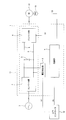
- the motor control device 1 includes a converter unit 2, a smoothing capacitor 3, an inverter unit 4, a voltage detection unit 5, and a control unit 6.
- the converter unit 2 converts AC power supplied from the AC power source 7 into DC power.
- the smoothing capacitor 3 is connected in parallel with the DC power supply to the positive DC bus 8 and the negative DC bus 9, and smoothes the DC power converted by the converter unit 2.
- the inverter unit 4 converts DC power into AC power based on a control signal S1 (PWM signal or the like) from the control unit 6, and drives the motor 10.
- S1 PWM signal or the like
- the voltage detection unit 5 is connected to the positive side DC bus 8 and the negative side DC bus 9 and detects the DC voltage of the main circuit 11. Further, the voltage detection unit 5 sets a predetermined voltage that is an undervoltage threshold value by a parameter, and generates a warning signal S2 and outputs the warning signal S2 to the host controller 12 when the DC voltage is lower than the predetermined voltage. When the voltage exceeds (returns) the voltage, the output of the warning signal S2 is stopped. While the warning signal S ⁇ b> 2 is input from the voltage detection unit 5, the host controller 12 outputs a torque limit signal (not shown) to the function enable / disable processing unit 20 described later of the control unit 6. The control unit 6 mainly controls the inverter unit 4 based on the position command Pr from the host controller 12.
- the voltage detection unit 5 outputs the warning signal S2 to the host controller 12 so that the first torque limit is performed via the host controller 12.
- the present invention is not limited to this. That is, the voltage detection unit 5 may directly output the warning signal S2 to the control unit 6 so that the first torque limit is performed without using the host controller 12.
- the position detector 13 optically or magnetically detects the motor position (rotation angle or the like) of the motor 10 to generate position data, and outputs the position data to the control unit 6 as a pulse signal S3.
- the control unit 6 captures the pulse signal S3 as a fed back motor position Pfb (see FIG. 2), converts it into a speed by a difference calculation or the like, and captures it as a fed back motor speed Vfb (see FIG. 2).
- the form of position data output by the position detector 13 is not limited to a pulse signal, and there are various forms such as serial data and analog sine waves.
- the control unit 6 includes a position control unit 14, a speed limiting unit 15, a speed control unit 16, a torque limiting unit 17, a limit value variable unit 18, a gain adjusting unit 19, and a function. And an invalid / invalid processing unit 20.
- the position control unit 14 generates a speed command Vr based on the position deviation Pe between the position command Pr from the host controller 12 and the motor position Pfb fed back from the position detector 13.
- the speed limiter 15 limits the command speed based on the speed command Vr (hereinafter referred to as “command speed Vr” as appropriate) to a predetermined speed limit value Vlim or less.
- the speed limit value Vlim is set to an arbitrary value as a parameter, and is variable by the limit value variable unit 18.
- the speed limiting function by the speed limiting unit 15 is enabled by the function valid / invalid processing unit 20 when a first torque limit described later by the torque limiting unit 17 is released, and the positional deviation Pe becomes equal to or less than a predetermined positional deviation.
- the speed limiter 15 actually starts the speed limit when the command speed Vr becomes equal to or higher than the speed limit value Vlim within the effective period, and limits the speed when the command speed Vr becomes less than the speed limit value Vlim. To release.
- the speed control unit 16 generates a torque command Tr based on the speed deviation Ve between the speed command Vr and the motor speed Vfb fed back from the position detector 13.
- the torque limiting unit 17 limits the command torque based on the torque command Tr (hereinafter referred to as “command torque Tr” as appropriate) to a predetermined torque limit value Tlim or less.
- the torque limit value Tlim is set to an arbitrary value as a parameter.
- the torque limiting function by the torque limiting unit 17 is activated by the function validation / invalidation processing unit 20 when the above-described torque limitation signal is input from the host controller 12, and functions when the input of the torque limitation signal is stopped. Invalidated by the valid / invalid processing unit 20.
- the torque limiter 17 actually starts the torque limit when the command torque Tr becomes equal to or greater than the torque limit value Tlim within the effective period, and performs the torque limit when the command torque Tr becomes less than the torque limit value Tlim. To release.
- first torque limitation In order to distinguish from the torque limitation that is limited to the above, it is referred to as “first torque limitation” as appropriate.
- the torque command Tr from the speed control unit 16 is converted into the control signal S1 described above and output to the inverter unit 4. In addition, you may make it the control part 6 have a torque control part (illustration omitted).
- the torque control unit converts the torque command Tr from the speed control unit 16 into a current command, generates a voltage command from the current command and the fed back motor current, and generates a control signal S1 based on the voltage command.
- the limit value variable unit 18 varies the speed limit value Vlim of the speed limit unit 15.
- the variable range and mode are arbitrarily set using, for example, an upper limit value, a lower limit value, and a variable time as parameters.
- the speed limit value Vlim may be varied so that the command speed Vr changes linearly at a constant acceleration or deceleration, or the speed such that the command speed Vr changes in a curve by changing the acceleration or the like.
- the limit value Vlim may be varied.
- the acceleration or the like is varied, for example, the acceleration may be varied according to the difference between the speed limit value Vlim and the position command speed dP that is a time differential value of the position command Pr. In this embodiment, as shown in FIG.
- the command speed Vr is changed from a speed V2 (corresponding to an example of a second speed), which is a motor speed at the time of releasing the first torque restriction, to a speed V1 (an example of the first speed).
- the limit value variable unit 18 varies the speed limit value Vlim so as to linearly accelerate at a constant acceleration until the speed limit value Vlim is reached. If the motor speed V2 at the time of releasing the first torque limit is greater than the speed V1, the command speed Vr is linearly decelerated at a constant deceleration from the speed V2 to the speed V1.
- the gain adjusting unit 19 is provided with the position control unit 14 when at least one of the case where the first torque limiting function by the torque limiting unit 17 is disabled or the case where the speed limiting function by the speed limiting unit 15 is enabled. At least one of the position loop gain and the speed loop gain of the speed controller 16 is reduced. Further, when the position deviation Pe is equal to or less than the predetermined position deviation, the gain adjusting unit 19 returns the lowered loop gain to the value before the reduction.
- the gain adjustment unit 19 that restores the loop gain corresponds to an example of a function invalidation processing unit.
- the voltage detection unit 5 detects that the DC voltage of the main circuit 11 is lower than the predetermined voltage V0 (time t1)
- the voltage detection unit 5 generates the warning signal S2 and outputs it to the host controller 12 as described above.
- the host controller 12 outputs a torque limit signal to the function validity / invalidity processing unit 20.
- the function validation / invalidation processing unit 20 validates the torque limiting function of the torque limiting unit 17.
- the torque limiter 17 immediately starts the first torque limit.
- the timing at which the torque limiting function of the torque limiting unit 17 becomes effective and the timing at which the torque limiting unit 17 actually starts the first torque limitation are almost simultaneous.
- the motor speed Vfb decreases due to the execution of the first torque limit, and the command speed Vr increases as the position deviation Pe increases. Until time t1, the position command speed dP, the command speed Vr, and the motor speed Vfb are substantially the same value.
- the voltage detector 5 stops outputting the warning signal S2 to the host controller 12, and the host controller 12 stops the output of the torque limit signal to the function valid / invalid processing unit 20.
- the function valid / invalid processing unit 20 invalidates the torque limiting function of the torque limiting unit 17.
- the torque limiting unit 17 performs the first torque limitation until just before the invalidation, so that the timing when the torque limiting function of the torque limiting unit 17 becomes invalid and the torque limiting unit 17 actually cancels the first torque limitation. The timing to do is almost the same time.
- the function valid / invalid processing unit 20 validates the speed restriction function by the speed restriction unit 15.
- the limit value variable unit 18 latches the speed limit value Vlim at the speed V2 that is the motor speed when the first torque limit is released.
- the timing at which the speed limiting function of the speed limiting unit 15 becomes effective and the timing at which the speed limiting unit 15 actually starts the speed limitation are almost simultaneous.
- the limit value variable unit 18 increases the speed limit value Vlim at a constant ratio to a speed V1 that is greater than the speed V2.
- the command speed Vr is linearly accelerated at a constant acceleration from the speed V2 to the speed V1.
- the speed limiter 15 releases the speed limit (time t3).
- the function validation / invalidation processing unit 20 invalidates the speed limiting function by the speed limiting unit 15. Note that after the time t2, the command speed Vr and the motor speed Vfb are substantially the same value.
- the gain The adjustment unit 19 reduces the loop gain.
- the loop gain may be either one or both of the position loop gain of the position control unit 14 and the speed loop gain of the speed control unit 16, but it is preferable to reduce the position loop gain of the position control unit 14 here. This is because the gain reduction start timing and the speed limit start timing are almost simultaneous, and the speed limit is executed by the speed limiter 15 when the gain is changed, so that there is no influence of the shock accompanying the gain change. Thereafter, when the position deviation Pe becomes equal to or smaller than the predetermined position deviation (time t4), the gain adjusting unit 19 returns the value to the value before the loop gain is lowered.
- the timing for releasing the first torque limit and starting the speed limit is shown as simultaneous at time t2 in FIG. 3, but it is shifted to both timings depending on the time required for signal transmission / reception with the host controller 12 and signal processing. May occur. Therefore, the start timing of the gain reduction may be set when the speed limit function by the speed limiter 15 is enabled (in the example shown in FIG. 3, the same timing as when the speed limiter 15 starts speed limit). . As a result, the gain can be surely reduced with the start of the speed limit.
- the motor 10 cannot follow the position command Pr, and the position deviation Pe may increase.
- the motor speed Vfb suddenly increases due to the speed command Vr corresponding to the increased position deviation Pe, and the motor 10 may overshoot and stop due to the occurrence of an overspeed alarm AL.
- the motor speed at this time is indicated by a one-dot chain line Vfb 'in FIG. 3).
- the limit value variable unit 18 varies the speed limit value Vlim of the speed limit unit 15 and gradually changes the command speed Vr from the speed V2 to the speed V1 at a predetermined acceleration. The sudden acceleration of the motor 10 at the time can be avoided to reduce the shock to the apparatus, and the operation of the motor 10 can be made smooth.
- the gain adjusting unit 19 reduces at least one of the position loop gain by the position control unit 14 or the speed loop gain by the speed control unit 16.
- the gain adjustment unit 19 corresponds to an example of a change mitigation unit.
- the gain adjusting unit 19 reduces the gain when the first torque limit is released or when the speed limit is started, the effect of changing the speed limit value Vlim as well as the effect of changing the speed limit value Vlim described above can be obtained.
- the effect of alleviating steep changes can be obtained synergistically.
- the speed limit value Vlim is not changed by the limit value changing unit 18 in the above embodiment. You may do it.
- the function validity / invalidity processing unit 20 releases the speed restriction by the speed restriction unit 15,
- the gain adjusting unit 19 restores the value before the loop gain is reduced. As a result, it is possible to reliably prevent the subsequent normal motor control from being affected without releasing the speed limit or returning to the value before the loop gain is lowered.
- the control unit 6 ⁇ / b> A of the present modification differs from the control unit 6 described above in that it has a limit value variable unit 18 ⁇ / b> A instead of the limit value variable unit 18 and does not have a gain adjustment unit 19. Is a point.
- Limit value variable unit 18A (corresponding to an example of a change mitigation unit) is a speed limit value of speed limiter 15 at a predetermined timing when speed limit is set to a command speed Vr of V1 or less by speed limiter 15. Vlim is varied, and the command speed Vr is decelerated from the speed V1 to a speed of 0 with a predetermined deceleration.
- the predetermined deceleration dec is set to an arbitrary value as a parameter.
- the limit value variable unit 18A varies the speed limit value Vlim so that the command speed Vr is accelerated from the speed V2 to the speed V1 when the first torque limit is released, similar to the limit value variable unit 18 described above. is there.
- the deceleration distance L as shown in equation (4) becomes V1 2 / 2dec. Since the speed V1 and the deceleration dec are set as parameters, the deceleration distance L is determined. Therefore, the limit value variable portion 18A monitors the position deviation Pe between the positional command Pr and the motor position Pfb, when the position deviation Pe is smaller than V1 2 / 2dec, starts decelerating command speed Vr.
- FIG. 6 shows an example of the operation of the motor control device 1 of this modification.
- the limit value variable unit 18A monitors the position deviation Pe when the speed limit unit 15 performs speed limit to set the command speed to V1 or less, and when the position deviation Pe becomes smaller than the deceleration distance L (time t5) Deceleration of the command speed Vr is started. Then, the limit value variable unit 18A varies the speed limit value Vlim of the speed limit unit 15 and decelerates the command speed Vr from the speed V1 until the speed becomes zero at a predetermined deceleration. When the command speed Vr becomes 0 (time t6), the function valid / invalid processing unit 20 invalidates the speed limit function by the speed limit unit 15. Since the speed limiting unit 15 performs speed limiting until immediately before the invalidation, the timing when the speed limiting function of the speed limiting unit 15 becomes invalid and the timing when the speed limiting unit 15 actually cancels the speed limitation. , Almost at the same time.
- the limit value variable unit 18A allows the speed limit value of the speed limiter 15 so that the command speed Vr is decelerated from the speed V1 with a predetermined deceleration.
- the motor 10 is decelerated and stopped in a state in which Vlim is varied and the speed is limited.
- Vlim is varied and the speed is limited.
- control unit has a low-pass filter
- a low-pass filter that removes high-frequency components of the speed command Vr may be provided. Conceivable. This modification will be described with reference to FIGS.
- the control unit 6B of the present modification has a low-pass filter 21 that removes a high-frequency component of the speed command Vr.
- the function validation / invalidation processing unit 20 (corresponding to an example of a function validation processing unit, a function invalidation processing unit, and a change mitigation unit) validates the filter function of the low-pass filter 21 at the start of speed limitation by the speed limitation unit 15.
- the control unit 6B does not have the gain adjustment unit 19.
- Other configurations are the same as those of the above-described embodiment (FIG. 2).
- FIG. 8 shows an example of the operation of the motor control device 1 of this modification.
- the function validation / invalidation processing unit 20 validates the filter function of the low-pass filter 21 at the start of speed limitation by the speed limitation unit 15 (time t2).
- the filter function of the low-pass filter 21 works to remove the high frequency component of the speed command Vr (time t3).
- the position deviation Pe becomes equal to or smaller than the predetermined position deviation (time t4)
- the function valid / invalid processing unit 20 invalidates the speed limiting function by the speed limiting unit 15 and invalidates the filter function.
- a sudden change in the command speed Vr can be suppressed, a sudden deceleration of the motor 10 can be avoided, a shock to the apparatus can be reduced, and the operation of the motor 10 can be smoothed. Further, since the filter function is invalidated when the position deviation Pe is equal to or smaller than the predetermined position deviation, it is ensured that the filter function of the low-pass filter 21 is not invalidated and affects the subsequent normal motor control. Can be prevented.
- the control unit 6 ⁇ / b> C of the present modification differs from the control unit 6 described above in that it has a torque limiting unit 17 ⁇ / b> C instead of the torque limiting unit 17 and does not have a gain adjusting unit 19. is there.
- the torque limit value T2 is set to an arbitrary value as a parameter.
- the second torque limiting function by the torque limiting unit 17C is enabled by the function valid / invalid processing unit 20 (corresponding to an example of a change mitigating unit) at the start of the speed limiting by the speed limiting unit 15 (time t2), and the position deviation Pe. Is invalidated by the function validation / invalidation processing unit 20 when the value becomes equal to or less than the predetermined position deviation (time t4).
- FIG. 10 shows an example of the operation of the motor control device 1 of this modification.
- the command torque Tr greatly fluctuates to the negative side (indicated by a one-dot chain line Tr ′ in FIG. 10).
- Tr ′ in FIG. 10
- the function effective processing unit 20 makes the second torque limit effective at the start of the speed limit and the command speed Vr deviates from the command speed limit (when the command torque Tr becomes T2 or less).
- the second torque limit is applied to the torque command Tr based on the motor position Pfb and the motor speed Vfb.
Abstract
Description
まず、図1を用いて本実施形態に係るモータ制御装置1の機能構成について説明する。図1に示すように、モータ制御装置1は、コンバータ部2と、平滑コンデンサ3と、インバータ部4と、電圧検出部5と、制御部6と、を有している。
次に、図2を用いて制御部6の機能構成について説明する。図2に示すように、制御部6は、位置制御部14と、速度制限部15と、速度制御部16と、トルク制限部17と、制限値可変部18と、ゲイン調整部19と、機能有効無効処理部20と、を有している。
次に、図3を用いて、瞬時停電等による主回路11の直流電圧の低下が発生した場合のモータ制御装置1の動作の一例について説明する。ここでは、位置指令Prの時間微分値である位置指令速度dPに示すように、位置指令Prの速度プロファイルが加速、定速、減速であり、この定速期間中に主回路電源電圧の低下が生じた場合について説明する。
以上説明したように、本実施形態のモータ制御装置1においては、電圧検出部5により主回路11の直流電圧が所定電圧V0を下回ったことが検出された場合に、トルク制限部17が指令トルクTrをトルク制限値Tlim(=T1)以下に制限する。これにより、モータ10を低トルクで駆動させて電力消費を少なくすることができるので、瞬時停電等により主回路電源電圧の低下が発生した場合でもモータ10を駆動し続けることができる。
なお、本発明は、上記実施形態に限られるものではなく、その趣旨及び技術的思想を逸脱しない範囲内で種々の変形が可能である。以下、そのような変形例を順を追って説明する。
上記実施形態では、指令速度Vrが指令速度制限から外れる際に、ループゲインを低下させることによって指令速度の急峻な変化を緩和させるようにしたが、変化を緩和させる手段はこれに限定されるものではない。例えば、制限値可変部18により速度制限値を可変させ、指令速度Vrを徐々に減速させることによって指令速度Vrの急峻な変化を緩和させてもよい。図4乃至図6を用いて本変形例について説明する。
指令速度Vrが指令速度制限から外れる際の変化を緩和させる手段としては、上記以外に例えば、速度指令Vrの高周波成分を除去するローパスフィルタを設けることが考えられる。図7及び図8を用いて本変形例について説明する。
指令速度Vrが指令速度制限から外れる際の変化を緩和させる手段としては、上記以外に例えば、指令速度Vrが指令速度制限から外れる際のトルク指令Trの負側への振れをトルク制限部17により制限することが考えられる。図9及び図10を用いて本変形例について説明する。
2 コンバータ部
3 平滑コンデンサ
4 インバータ部
5 電圧検出部
6 制御部
6A~6C 制御部
7 交流電源
10 モータ
11 主回路
12 上位コントローラ
13 位置検出器
14 位置制御部
15 速度制限部
16 速度制御部
17 トルク制限部
17C トルク制限部
18 制限値可変部
18A 制限値可変部(変化緩和部)
19 ゲイン調整部(変化緩和部、機能無効処理部)
20 機能有効無効処理部(機能無効処理部、機能有効処理部、変化緩和部)
21 ローパスフィルタ
Pr 位置指令
Vr 速度指令
Tr トルク指令
Pfb モータ位置
Vfb モータ速度
Claims (8)
- 交流電源を直流電源に変換するコンバータ部、前記直流電源と並列に接続された平滑コンデンサ、及び、前記直流電源を交流電源に変換しモータを駆動するインバータ部を有する主回路と、
前記主回路の直流電圧を検出する電圧検出部と、
位置指令とモータ位置から速度指令を生成する位置制御部、及び、前記速度指令とモータ速度からトルク指令を生成する速度制御部を有し、前記トルク指令に基づき前記インバータ部を制御する制御部と、を備え、
前記制御部は、
前記電圧検出部により前記直流電圧が所定電圧を下回ったことが検出された場合に、前記トルク指令による指令トルクを第1トルク以下に制限する第1トルク制限を開始し、前記直流電圧が前記所定電圧を上回ったことが検出された場合に、前記第1トルク制限を解除するトルク制限部と、
前記トルク制限部が前記第1トルク制限を解除した場合に、前記速度指令による指令速度を第1速度以下に制限する速度制限部と、を有する
ことを特徴とするモータ制御装置。 - 前記制御部は、
前記指令速度が前記第1トルク制限の解除時の前記モータ速度である第2速度から前記第1速度に至るまで所定の加速度又は減速度で変化するように、前記速度制限部の速度制限値を可変させる、制限値可変部をさらに有する
ことを特徴とする請求項1に記載のモータ制御装置。 - 前記制御部は、
前記トルク制限部が前記第1トルク制限を解除した場合又は前記速度制限部が速度制限を開始した場合に、前記位置制御部又は前記速度制御部の少なくとも一方のループゲインを低下させるゲイン調整部をさらに有する
ことを特徴とする請求項1又は2に記載のモータ制御装置。 - 前記制御部は、
前記指令速度が指令速度制限から外れた場合に、前記モータ位置又は前記モータ速度の少なくともいずれか一方に基づいて前記指令速度の急峻な変化を緩和させる変化緩和部を有する
ことを特徴とする請求項1乃至3のいずれか1項に記載のモータ制御装置。 - 前記変化緩和部は、
前記位置指令と前記モータ位置との位置偏差が、前記第1速度から所定の減速度で減速させた場合に前記モータが停止までに必要な減速距離より小さくなった場合に、前記指令速度が前記第1速度から前記所定の減速度で減速するように、前記速度制限部の速度制限値を可変させる制限値可変部である
ことを特徴とする請求項4に記載のモータ制御装置。 - 前記制御部は、
前記速度指令の高周波成分を除去するローパスフィルタを有し、
前記変化緩和部は、
前記速度制限部による速度制限の開始時に、前記ローパスフィルタのフィルタ機能を有効にする機能有効処理部である
ことを特徴とする請求項4に記載のモータ制御装置。 - 前記変化緩和部は、
前記速度制限部による速度制限の開始時に、前記指令トルクを第2トルク以上に制限する第2トルク制限を有効にする機能有効処理部である
ことを特徴とする請求項4に記載のモータ制御装置。 - 前記位置指令と前記モータ位置との位置偏差が所定の位置偏差以下となった場合に、前記速度制限部による速度制限を解除し、又は、前記ループゲインを低下させる前の値に復帰させ、又は、前記フィルタ機能を無効にし、又は、前記第2トルク制限を解除する、機能無効処理部をさらに有する
ことを特徴とする請求項1乃至7のいずれか1項に記載のモータ制御装置。
Priority Applications (6)
| Application Number | Priority Date | Filing Date | Title |
|---|---|---|---|
| PCT/JP2012/054607 WO2013125034A1 (ja) | 2012-02-24 | 2012-02-24 | モータ制御装置 |
| CN201280070654.0A CN104137414A (zh) | 2012-02-24 | 2012-02-24 | 电机控制装置 |
| JP2012554553A JP5246458B1 (ja) | 2012-02-24 | 2012-02-24 | モータ制御装置 |
| KR1020147023374A KR20140121853A (ko) | 2012-02-24 | 2012-02-24 | 모터 제어 장치 |
| EP12869285.2A EP2819300B1 (en) | 2012-02-24 | 2012-02-24 | Motor control apparatus |
| US14/464,707 US9342057B2 (en) | 2012-02-24 | 2014-08-21 | Motor control apparatus |
Applications Claiming Priority (1)
| Application Number | Priority Date | Filing Date | Title |
|---|---|---|---|
| PCT/JP2012/054607 WO2013125034A1 (ja) | 2012-02-24 | 2012-02-24 | モータ制御装置 |
Related Child Applications (1)
| Application Number | Title | Priority Date | Filing Date |
|---|---|---|---|
| US14/464,707 Continuation US9342057B2 (en) | 2012-02-24 | 2014-08-21 | Motor control apparatus |
Publications (1)
| Publication Number | Publication Date |
|---|---|
| WO2013125034A1 true WO2013125034A1 (ja) | 2013-08-29 |
Family
ID=49005251
Family Applications (1)
| Application Number | Title | Priority Date | Filing Date |
|---|---|---|---|
| PCT/JP2012/054607 WO2013125034A1 (ja) | 2012-02-24 | 2012-02-24 | モータ制御装置 |
Country Status (6)
| Country | Link |
|---|---|
| US (1) | US9342057B2 (ja) |
| EP (1) | EP2819300B1 (ja) |
| JP (1) | JP5246458B1 (ja) |
| KR (1) | KR20140121853A (ja) |
| CN (1) | CN104137414A (ja) |
| WO (1) | WO2013125034A1 (ja) |
Cited By (1)
| Publication number | Priority date | Publication date | Assignee | Title |
|---|---|---|---|---|
| US11835047B2 (en) | 2019-08-28 | 2023-12-05 | Ebara Corporation | Pump apparatus |
Families Citing this family (10)
| Publication number | Priority date | Publication date | Assignee | Title |
|---|---|---|---|---|
| BR112016021650B1 (pt) * | 2014-03-27 | 2022-07-05 | Daikin Industries, Ltd | Dispositivo de conversão de energia |
| KR101575294B1 (ko) * | 2014-06-02 | 2015-12-21 | 현대자동차 주식회사 | 인버터의 입력단 전압 추정 방법 및 이를 이용한 모터 제어 방법 |
| JP6323206B2 (ja) * | 2014-06-23 | 2018-05-16 | 株式会社リコー | 画像形成装置、画像形成方法およびプログラム |
| JP6623987B2 (ja) * | 2016-09-09 | 2019-12-25 | 株式会社デンソー | シフトレンジ制御装置 |
| CN106647836A (zh) * | 2016-11-23 | 2017-05-10 | 河池学院 | 机器人传动电机速度环调整方法 |
| US10911061B2 (en) * | 2018-03-23 | 2021-02-02 | The Boeing Company | System and method for demodulation of resolver outputs |
| US10913550B2 (en) * | 2018-03-23 | 2021-02-09 | The Boeing Company | System and method for position and speed feedback control |
| US10830591B2 (en) | 2018-03-23 | 2020-11-10 | The Boeing Company | System and method for dual speed resolver |
| US10673368B2 (en) | 2018-03-23 | 2020-06-02 | The Boeing Company | System and method for pulse-width modulation using an adjustable comparison criterion |
| JP7188143B2 (ja) | 2019-01-31 | 2022-12-13 | 株式会社明電舎 | 異常予兆検出システム、異常予兆検出方法 |
Citations (4)
| Publication number | Priority date | Publication date | Assignee | Title |
|---|---|---|---|---|
| JPH0822330A (ja) * | 1994-07-08 | 1996-01-23 | Okuma Mach Works Ltd | サーボ制御装置 |
| WO2008093485A1 (ja) | 2007-01-31 | 2008-08-07 | Kabushiki Kaisha Yaskawa Denki | モータ制御装置 |
| JP2009227147A (ja) * | 2008-03-24 | 2009-10-08 | Aisin Aw Co Ltd | ハイブリッド駆動装置 |
| JP2012039847A (ja) * | 2010-08-08 | 2012-02-23 | Nidec Sankyo Corp | モータ制御装置およびモータ制御方法 |
Family Cites Families (28)
| Publication number | Priority date | Publication date | Assignee | Title |
|---|---|---|---|---|
| JPH0767312B2 (ja) * | 1986-12-29 | 1995-07-19 | 富士電機株式会社 | 磁束制御形pwmインバ−タの制御装置 |
| JP3084928B2 (ja) * | 1992-05-29 | 2000-09-04 | 三菱電機株式会社 | 電動機の位置制御装置 |
| JPH07115791A (ja) * | 1993-10-13 | 1995-05-02 | Nippondenso Co Ltd | 電気自動車用制御装置 |
| EP0753933B1 (en) * | 1995-01-27 | 2001-03-21 | Kabushiki Kaisha Yaskawa Denki | Method for starting permanent magnet synchronous motor with rotational position detector, and motor controller |
| JP2858692B2 (ja) * | 1996-12-05 | 1999-02-17 | 株式会社安川電機 | 永久磁石型同期電動機のセンサレス制御方法及び装置 |
| CN1146765C (zh) * | 1998-09-28 | 2004-04-21 | 株式会社安川电机 | 位置控制装置 |
| KR100312771B1 (ko) * | 1998-12-15 | 2002-05-09 | 장병우 | 엘리베이터의정전운전제어장치및방법 |
| JP3164570B2 (ja) * | 1999-09-16 | 2001-05-08 | ファナック株式会社 | スクリュあるいはスクリュヘッドの過負荷検出装置 |
| JP3454210B2 (ja) * | 1999-11-30 | 2003-10-06 | 株式会社日立製作所 | 同期モータの位置センサレス制御方法 |
| JP3622666B2 (ja) * | 2000-11-06 | 2005-02-23 | ダイキン工業株式会社 | 同期モータ制御方法およびその装置 |
| US6683428B2 (en) * | 2002-01-30 | 2004-01-27 | Ford Global Technologies, Llc | Method for controlling torque in a rotational sensorless induction motor control system with speed and rotor flux estimation |
| US7002315B2 (en) * | 2002-05-28 | 2006-02-21 | Toshiba Kikai Kabushiki Kaisha | Servo control device |
| JP3850363B2 (ja) * | 2002-10-21 | 2006-11-29 | 山洋電気株式会社 | モータの位置制御装置 |
| JP2004266887A (ja) * | 2003-02-14 | 2004-09-24 | Yaskawa Electric Corp | 交流電動機の制御方法及び制御装置 |
| JP2005216135A (ja) * | 2004-01-30 | 2005-08-11 | Fanuc Ltd | ねじ切り・ねじ立て加工用制御装置 |
| JP2005219133A (ja) * | 2004-02-03 | 2005-08-18 | Fanuc Ltd | ロボット用サーボモータ制御装置およびロボット |
| JP2005289532A (ja) * | 2004-03-31 | 2005-10-20 | Mitsubishi Electric Corp | エレベータ制御装置 |
| CA2683320C (en) * | 2004-06-18 | 2010-08-17 | Unico, Inc. | Method and system for improving pump efficiency and productivity under power disturbance conditions |
| US7332884B2 (en) | 2004-07-16 | 2008-02-19 | Hamilton Sundstrand Corporation | Electric motor control strategies |
| JP2006122944A (ja) * | 2004-10-28 | 2006-05-18 | Fanuc Ltd | ダイクッション制御装置 |
| JP4299793B2 (ja) * | 2005-01-20 | 2009-07-22 | ファナック株式会社 | 制御装置 |
| JP4577107B2 (ja) * | 2005-06-17 | 2010-11-10 | 三菱電機株式会社 | 機械位置制御装置 |
| JP4085112B2 (ja) * | 2006-01-31 | 2008-05-14 | ファナック株式会社 | モータ制御方法およびモータ制御装置 |
| DE112006004105T5 (de) * | 2006-12-15 | 2009-08-27 | Mitsubishi Electric Corporation | Invertereinrichtung |
| EP2012207B1 (en) * | 2007-07-02 | 2016-11-23 | Fanuc Corporation | Numerical controller controlling acceleration and deceleration of respective control axes up to command speeds |
| JP4540727B2 (ja) * | 2008-07-31 | 2010-09-08 | 山洋電気株式会社 | モータ制御装置 |
| JP4565034B2 (ja) * | 2008-12-16 | 2010-10-20 | ファナック株式会社 | イナーシャ推定を行う制御装置及び制御システム |
| US8604386B2 (en) * | 2010-03-10 | 2013-12-10 | Illinois Tool Works, Inc. | Welding wire feeding systems and methods |
-
2012
- 2012-02-24 WO PCT/JP2012/054607 patent/WO2013125034A1/ja active Application Filing
- 2012-02-24 CN CN201280070654.0A patent/CN104137414A/zh active Pending
- 2012-02-24 JP JP2012554553A patent/JP5246458B1/ja active Active
- 2012-02-24 EP EP12869285.2A patent/EP2819300B1/en active Active
- 2012-02-24 KR KR1020147023374A patent/KR20140121853A/ko active IP Right Grant
-
2014
- 2014-08-21 US US14/464,707 patent/US9342057B2/en active Active
Patent Citations (4)
| Publication number | Priority date | Publication date | Assignee | Title |
|---|---|---|---|---|
| JPH0822330A (ja) * | 1994-07-08 | 1996-01-23 | Okuma Mach Works Ltd | サーボ制御装置 |
| WO2008093485A1 (ja) | 2007-01-31 | 2008-08-07 | Kabushiki Kaisha Yaskawa Denki | モータ制御装置 |
| JP2009227147A (ja) * | 2008-03-24 | 2009-10-08 | Aisin Aw Co Ltd | ハイブリッド駆動装置 |
| JP2012039847A (ja) * | 2010-08-08 | 2012-02-23 | Nidec Sankyo Corp | モータ制御装置およびモータ制御方法 |
Cited By (1)
| Publication number | Priority date | Publication date | Assignee | Title |
|---|---|---|---|---|
| US11835047B2 (en) | 2019-08-28 | 2023-12-05 | Ebara Corporation | Pump apparatus |
Also Published As
| Publication number | Publication date |
|---|---|
| EP2819300A1 (en) | 2014-12-31 |
| JP5246458B1 (ja) | 2013-07-24 |
| CN104137414A (zh) | 2014-11-05 |
| EP2819300A4 (en) | 2016-04-06 |
| EP2819300B1 (en) | 2019-04-10 |
| US9342057B2 (en) | 2016-05-17 |
| JPWO2013125034A1 (ja) | 2015-07-30 |
| US20140354208A1 (en) | 2014-12-04 |
| KR20140121853A (ko) | 2014-10-16 |
Similar Documents
| Publication | Publication Date | Title |
|---|---|---|
| JP5246458B1 (ja) | モータ制御装置 | |
| TWI243532B (en) | Inverter device and current limiting method therefor | |
| JP5689704B2 (ja) | モータ制御装置およびモータ制御方法 | |
| JP4053557B2 (ja) | サーボモータ停止制御方法及びサーボモータ制御装置 | |
| JP6377985B2 (ja) | 停電時におけるトルク指令制限機能を備えたモータ制御装置 | |
| US8786239B2 (en) | Motor drive PWM rectifier having modulation scheme selector | |
| US20130154536A1 (en) | Apparatus for controlling an inverter | |
| WO2013140500A1 (ja) | モータ制御装置 | |
| WO2017006485A1 (ja) | モータ制御装置 | |
| US20060181240A1 (en) | Method and system for managing the voltage on the DC bus of a speed controller for an AC motor | |
| TWI523405B (zh) | 馬達減速方法及其適用之馬達驅動系統 | |
| JPH11308894A (ja) | 電動機の停電時処理方法 | |
| JP6421598B2 (ja) | 電動機の制御装置及び制御方法 | |
| US11056994B2 (en) | Electric machine controlling method and electric machine controlling device | |
| US11296637B2 (en) | Control device | |
| JP2009055715A (ja) | インバータ装置と停電時処理方法 | |
| US9281765B2 (en) | Motor deceleration method and motor driving system using the same | |
| JP2008154335A (ja) | インバータ装置と過電圧抑制方法 | |
| EP3001559B1 (en) | Active dead band for noise reduction in high response high bandwidth control systems | |
| US7126297B2 (en) | Controlling method of a motor state | |
| JP5361506B2 (ja) | 保護機能を備えた電動機制御装置 | |
| US10536105B2 (en) | Power conversion apparatus | |
| US20210257942A1 (en) | Brake circuit discharge system | |
| TWI401863B (zh) | 馬達再生電壓抑制之裝置及其方法 | |
| JP2013212772A (ja) | 自動制動装置 |
Legal Events
| Date | Code | Title | Description |
|---|---|---|---|
| ENP | Entry into the national phase |
Ref document number: 2012554553 Country of ref document: JP Kind code of ref document: A |
|
| 121 | Ep: the epo has been informed by wipo that ep was designated in this application |
Ref document number: 12869285 Country of ref document: EP Kind code of ref document: A1 |
|
| ENP | Entry into the national phase |
Ref document number: 20147023374 Country of ref document: KR Kind code of ref document: A |
|
| NENP | Non-entry into the national phase |
Ref country code: DE |
|
| WWE | Wipo information: entry into national phase |
Ref document number: 2012869285 Country of ref document: EP |