WO2013122158A1 - 電動リニアアクチュエータ - Google Patents
電動リニアアクチュエータ Download PDFInfo
- Publication number
- WO2013122158A1 WO2013122158A1 PCT/JP2013/053554 JP2013053554W WO2013122158A1 WO 2013122158 A1 WO2013122158 A1 WO 2013122158A1 JP 2013053554 W JP2013053554 W JP 2013053554W WO 2013122158 A1 WO2013122158 A1 WO 2013122158A1
- Authority
- WO
- WIPO (PCT)
- Prior art keywords
- housing
- linear actuator
- electric linear
- sleeve
- retaining ring
- Prior art date
Links
- 230000007246 mechanism Effects 0.000 claims abstract description 42
- 229910052782 aluminium Inorganic materials 0.000 claims description 9
- XAGFODPZIPBFFR-UHFFFAOYSA-N aluminium Chemical compound [Al] XAGFODPZIPBFFR-UHFFFAOYSA-N 0.000 claims description 9
- 229910001234 light alloy Inorganic materials 0.000 claims description 6
- 229910045601 alloy Inorganic materials 0.000 claims description 4
- 239000000956 alloy Substances 0.000 claims description 4
- 238000005255 carburizing Methods 0.000 claims description 4
- 238000010791 quenching Methods 0.000 claims description 3
- 230000000171 quenching effect Effects 0.000 claims description 3
- 238000004512 die casting Methods 0.000 claims description 2
- 230000000717 retained effect Effects 0.000 abstract description 3
- 230000004308 accommodation Effects 0.000 description 8
- 238000005096 rolling process Methods 0.000 description 7
- 239000000463 material Substances 0.000 description 5
- PXHVJJICTQNCMI-UHFFFAOYSA-N nickel Substances [Ni] PXHVJJICTQNCMI-UHFFFAOYSA-N 0.000 description 5
- 239000000843 powder Substances 0.000 description 5
- 238000001746 injection moulding Methods 0.000 description 4
- XEEYBQQBJWHFJM-UHFFFAOYSA-N iron Substances [Fe] XEEYBQQBJWHFJM-UHFFFAOYSA-N 0.000 description 4
- 229910052751 metal Inorganic materials 0.000 description 4
- 239000002184 metal Substances 0.000 description 4
- 230000002093 peripheral effect Effects 0.000 description 4
- 229910052804 chromium Inorganic materials 0.000 description 3
- 239000011651 chromium Substances 0.000 description 3
- 229910052802 copper Inorganic materials 0.000 description 3
- 239000010949 copper Substances 0.000 description 3
- 229910052759 nickel Inorganic materials 0.000 description 3
- 229910000838 Al alloy Inorganic materials 0.000 description 2
- 229910000760 Hardened steel Inorganic materials 0.000 description 2
- 230000005540 biological transmission Effects 0.000 description 2
- 238000011109 contamination Methods 0.000 description 2
- 238000010438 heat treatment Methods 0.000 description 2
- 230000007257 malfunction Effects 0.000 description 2
- 229910052748 manganese Inorganic materials 0.000 description 2
- 239000011572 manganese Substances 0.000 description 2
- 238000012986 modification Methods 0.000 description 2
- 230000004048 modification Effects 0.000 description 2
- 229910052750 molybdenum Inorganic materials 0.000 description 2
- 239000008188 pellet Substances 0.000 description 2
- 238000012805 post-processing Methods 0.000 description 2
- 230000036316 preload Effects 0.000 description 2
- 229910052710 silicon Inorganic materials 0.000 description 2
- OKTJSMMVPCPJKN-UHFFFAOYSA-N Carbon Chemical compound [C] OKTJSMMVPCPJKN-UHFFFAOYSA-N 0.000 description 1
- VYZAMTAEIAYCRO-UHFFFAOYSA-N Chromium Chemical compound [Cr] VYZAMTAEIAYCRO-UHFFFAOYSA-N 0.000 description 1
- RYGMFSIKBFXOCR-UHFFFAOYSA-N Copper Chemical compound [Cu] RYGMFSIKBFXOCR-UHFFFAOYSA-N 0.000 description 1
- PWHULOQIROXLJO-UHFFFAOYSA-N Manganese Chemical compound [Mn] PWHULOQIROXLJO-UHFFFAOYSA-N 0.000 description 1
- 229910000954 Medium-carbon steel Inorganic materials 0.000 description 1
- ZOKXTWBITQBERF-UHFFFAOYSA-N Molybdenum Chemical compound [Mo] ZOKXTWBITQBERF-UHFFFAOYSA-N 0.000 description 1
- 229910000831 Steel Inorganic materials 0.000 description 1
- 229910000963 austenitic stainless steel Inorganic materials 0.000 description 1
- 239000011230 binding agent Substances 0.000 description 1
- 229910052799 carbon Inorganic materials 0.000 description 1
- 238000006243 chemical reaction Methods 0.000 description 1
- 239000010960 cold rolled steel Substances 0.000 description 1
- 230000007797 corrosion Effects 0.000 description 1
- 238000005260 corrosion Methods 0.000 description 1
- 238000006073 displacement reaction Methods 0.000 description 1
- 239000004519 grease Substances 0.000 description 1
- 230000006698 induction Effects 0.000 description 1
- 229910052742 iron Inorganic materials 0.000 description 1
- 230000001050 lubricating effect Effects 0.000 description 1
- 238000004519 manufacturing process Methods 0.000 description 1
- 239000011733 molybdenum Substances 0.000 description 1
- 238000000465 moulding Methods 0.000 description 1
- 230000000149 penetrating effect Effects 0.000 description 1
- 230000035515 penetration Effects 0.000 description 1
- 238000004663 powder metallurgy Methods 0.000 description 1
- 238000001556 precipitation Methods 0.000 description 1
- 238000003825 pressing Methods 0.000 description 1
- 102220259718 rs34120878 Human genes 0.000 description 1
- 239000010703 silicon Substances 0.000 description 1
- 239000000243 solution Substances 0.000 description 1
- 239000010935 stainless steel Substances 0.000 description 1
- 229910001220 stainless steel Inorganic materials 0.000 description 1
- 239000010959 steel Substances 0.000 description 1
- 238000005496 tempering Methods 0.000 description 1
Images


Classifications
-
- F—MECHANICAL ENGINEERING; LIGHTING; HEATING; WEAPONS; BLASTING
- F16—ENGINEERING ELEMENTS AND UNITS; GENERAL MEASURES FOR PRODUCING AND MAINTAINING EFFECTIVE FUNCTIONING OF MACHINES OR INSTALLATIONS; THERMAL INSULATION IN GENERAL
- F16H—GEARING
- F16H25/00—Gearings comprising primarily only cams, cam-followers and screw-and-nut mechanisms
- F16H25/18—Gearings comprising primarily only cams, cam-followers and screw-and-nut mechanisms for conveying or interconverting oscillating or reciprocating motions
- F16H25/20—Screw mechanisms
- F16H25/22—Screw mechanisms with balls, rollers, or similar members between the co-operating parts; Elements essential to the use of such members
- F16H25/2204—Screw mechanisms with balls, rollers, or similar members between the co-operating parts; Elements essential to the use of such members with balls
-
- F—MECHANICAL ENGINEERING; LIGHTING; HEATING; WEAPONS; BLASTING
- F16—ENGINEERING ELEMENTS AND UNITS; GENERAL MEASURES FOR PRODUCING AND MAINTAINING EFFECTIVE FUNCTIONING OF MACHINES OR INSTALLATIONS; THERMAL INSULATION IN GENERAL
- F16H—GEARING
- F16H25/00—Gearings comprising primarily only cams, cam-followers and screw-and-nut mechanisms
- F16H25/18—Gearings comprising primarily only cams, cam-followers and screw-and-nut mechanisms for conveying or interconverting oscillating or reciprocating motions
- F16H25/20—Screw mechanisms
- F16H25/24—Elements essential to such mechanisms, e.g. screws, nuts
-
- F—MECHANICAL ENGINEERING; LIGHTING; HEATING; WEAPONS; BLASTING
- F16—ENGINEERING ELEMENTS AND UNITS; GENERAL MEASURES FOR PRODUCING AND MAINTAINING EFFECTIVE FUNCTIONING OF MACHINES OR INSTALLATIONS; THERMAL INSULATION IN GENERAL
- F16H—GEARING
- F16H25/00—Gearings comprising primarily only cams, cam-followers and screw-and-nut mechanisms
- F16H25/18—Gearings comprising primarily only cams, cam-followers and screw-and-nut mechanisms for conveying or interconverting oscillating or reciprocating motions
- F16H25/20—Screw mechanisms
- F16H25/22—Screw mechanisms with balls, rollers, or similar members between the co-operating parts; Elements essential to the use of such members
- F16H25/2204—Screw mechanisms with balls, rollers, or similar members between the co-operating parts; Elements essential to the use of such members with balls
- F16H25/2214—Screw mechanisms with balls, rollers, or similar members between the co-operating parts; Elements essential to the use of such members with balls with elements for guiding the circulating balls
-
- H—ELECTRICITY
- H02—GENERATION; CONVERSION OR DISTRIBUTION OF ELECTRIC POWER
- H02K—DYNAMO-ELECTRIC MACHINES
- H02K7/00—Arrangements for handling mechanical energy structurally associated with dynamo-electric machines, e.g. structural association with mechanical driving motors or auxiliary dynamo-electric machines
- H02K7/06—Means for converting reciprocating motion into rotary motion or vice versa
-
- F—MECHANICAL ENGINEERING; LIGHTING; HEATING; WEAPONS; BLASTING
- F16—ENGINEERING ELEMENTS AND UNITS; GENERAL MEASURES FOR PRODUCING AND MAINTAINING EFFECTIVE FUNCTIONING OF MACHINES OR INSTALLATIONS; THERMAL INSULATION IN GENERAL
- F16B—DEVICES FOR FASTENING OR SECURING CONSTRUCTIONAL ELEMENTS OR MACHINE PARTS TOGETHER, e.g. NAILS, BOLTS, CIRCLIPS, CLAMPS, CLIPS OR WEDGES; JOINTS OR JOINTING
- F16B21/00—Means for preventing relative axial movement of a pin, spigot, shaft or the like and a member surrounding it; Stud-and-socket releasable fastenings
- F16B21/10—Means for preventing relative axial movement of a pin, spigot, shaft or the like and a member surrounding it; Stud-and-socket releasable fastenings by separate parts
- F16B21/16—Means for preventing relative axial movement of a pin, spigot, shaft or the like and a member surrounding it; Stud-and-socket releasable fastenings by separate parts with grooves or notches in the pin or shaft
- F16B21/18—Means for preventing relative axial movement of a pin, spigot, shaft or the like and a member surrounding it; Stud-and-socket releasable fastenings by separate parts with grooves or notches in the pin or shaft with circlips or like resilient retaining devices, i.e. resilient in the plane of the ring or the like; Details
- F16B21/183—Means for preventing relative axial movement of a pin, spigot, shaft or the like and a member surrounding it; Stud-and-socket releasable fastenings by separate parts with grooves or notches in the pin or shaft with circlips or like resilient retaining devices, i.e. resilient in the plane of the ring or the like; Details internal, i.e. with spreading action
-
- F—MECHANICAL ENGINEERING; LIGHTING; HEATING; WEAPONS; BLASTING
- F16—ENGINEERING ELEMENTS AND UNITS; GENERAL MEASURES FOR PRODUCING AND MAINTAINING EFFECTIVE FUNCTIONING OF MACHINES OR INSTALLATIONS; THERMAL INSULATION IN GENERAL
- F16H—GEARING
- F16H25/00—Gearings comprising primarily only cams, cam-followers and screw-and-nut mechanisms
- F16H25/18—Gearings comprising primarily only cams, cam-followers and screw-and-nut mechanisms for conveying or interconverting oscillating or reciprocating motions
- F16H25/20—Screw mechanisms
- F16H2025/2062—Arrangements for driving the actuator
- F16H2025/2081—Parallel arrangement of drive motor to screw axis
-
- Y—GENERAL TAGGING OF NEW TECHNOLOGICAL DEVELOPMENTS; GENERAL TAGGING OF CROSS-SECTIONAL TECHNOLOGIES SPANNING OVER SEVERAL SECTIONS OF THE IPC; TECHNICAL SUBJECTS COVERED BY FORMER USPC CROSS-REFERENCE ART COLLECTIONS [XRACs] AND DIGESTS
- Y10—TECHNICAL SUBJECTS COVERED BY FORMER USPC
- Y10T—TECHNICAL SUBJECTS COVERED BY FORMER US CLASSIFICATION
- Y10T74/00—Machine element or mechanism
- Y10T74/18—Mechanical movements
- Y10T74/18568—Reciprocating or oscillating to or from alternating rotary
- Y10T74/18576—Reciprocating or oscillating to or from alternating rotary including screw and nut
Definitions
- the present invention relates to an electric linear actuator having a ball screw mechanism used in a drive unit of a general industrial electric motor or automobile, and more specifically, a rotational input from an electric motor is applied to a ball in a transmission or a parking brake of the automobile.
- the present invention relates to an electric linear actuator that converts a linear motion of a drive shaft through a screw mechanism.
- a trapezoidal screw or a gear mechanism such as a rack and pinion is generally used as a mechanism for converting the rotational motion of the electric motor into a linear motion in the axial direction. Since these conversion mechanisms involve a sliding contact portion, the power loss is large, and it is necessary to increase the size of the electric motor and increase the power consumption. Therefore, a ball screw mechanism has been adopted as a more efficient actuator.
- a ball screw shaft constituting a ball screw can be driven to rotate by an electric motor supported by a housing, and an output member coupled to a nut by rotating the ball screw shaft. Can be displaced in the axial direction. Since the ball screw mechanism has very low friction and the ball screw shaft easily rotates due to the thrust load acting on the output member side, it is necessary to hold the position of the output member when the electric motor is stopped.
- a brake means is provided in an electric motor, or a low-efficiency thing such as a worm gear is provided as a transmission means.
- an electric motor as shown in FIG. Linear actuators are known.
- the electric linear actuator 50 includes a ball screw shaft 51 that is rotationally driven by an electric motor (not shown), and a ball screw nut 52 that is screwed onto the ball screw shaft 51 via a ball (not shown).
- a ball screw mechanism 53 provided is employed.
- the ball screw shaft 51 is rotatably supported by cylindrical housings 54 and 55 by two rolling bearings 56 and 57. These rolling bearings 56 and 57 are fixed by a locking member 59 for preventing loosening via a fixing lid 58.
- a spiral screw groove 51a is formed on the outer periphery of the ball screw shaft 51, and a cylindrical ball screw nut 52 is screwed through the ball.
- a spiral screw groove 52a is formed on the inner periphery of the ball screw nut 52, and a large diameter portion 60 is formed at the end.
- a flat portion 61 is formed on the side surface of the large-diameter portion 60 and is cut so that the end surface is flat.
- a cam follower (rotation stop means) 62 projects from the substantially central portion of the flat portion 61 toward the outside in the radial direction.
- the present invention has been made in view of such problems of the prior art, and an object of the present invention is to provide an electric linear actuator that reduces sliding friction and wear, and has a simple structure and reduced cost. .
- the invention described in claim 1 of the present invention is a cylindrical housing made of an aluminum light alloy, an electric motor attached to the housing, and the rotational force of the electric motor as a motor shaft. And a ball screw mechanism that converts the rotational motion of the electric motor to a linear motion in the axial direction of the drive shaft via the speed reduction mechanism, and this ball screw mechanism is mounted on the housing.
- a nut that is rotatably supported through the pair of support bearings and is not axially movable, and has a helical thread groove formed on the inner periphery, and is inserted into the nut via a number of balls.
- a screw that is coaxially integrated with the drive shaft has a helical thread groove corresponding to the thread groove of the nut on the outer periphery, and is supported so as to be non-rotatable and axially movable with respect to the housing
- a cylindrical sleeve is fitted into the housing hole of the housing, and an axial direction is formed on the inner periphery of the sleeve.
- a pair of concave grooves are formed at opposite positions and a guide pin implanted at the end of the screw shaft is engaged, and an annular groove is formed in the opening of the housing hole of the housing, The sleeve is prevented from coming off while being pressed by a hole retaining ring mounted in the annular groove.
- a cylindrical housing made of aluminum light alloy, an electric motor attached to the housing, a reduction mechanism that transmits the rotational force of the electric motor through the motor shaft, and electric operation through the reduction mechanism.
- a ball screw mechanism that converts the rotational motion of the motor into a linear motion in the axial direction of the drive shaft.
- the ball screw mechanism is rotatable via a pair of support bearings mounted on the housing and cannot move in the axial direction.
- a cylindrical sleeve is fitted into the housing hole of the housing, extends in the axial direction on the inner periphery of the sleeve, and has a pair of concave grooves formed at opposite positions so as to be planted at the end of the screw shaft.
- An annular groove is formed in the opening of the housing accommodation hole, and the sleeve is prevented from coming off while being pressed by a retaining ring for a hole attached to the annular groove.
- the retaining ring is formed with a curved portion having an apex at least at one position at a position symmetrical with respect to the notch, the retaining ring An axial load is generated by the spring force, a predetermined preload can be applied to the sleeve, and the occurrence of wear, noise, or vibration of the housing can be reliably prevented.
- the retaining ring is formed by press working using a wire rod whose corners are previously rounded, post-processing is not required, and mass productivity is improved.
- the sleeve is formed of a sintered alloy that can be carburized and quenched as in the invention described in claim 6, even if the sleeve has a high workability and a complicated shape, it can be easily and accurately performed. It can be formed into a desired shape and size.
- the housing is formed by aluminum die casting, it is rich in mass productivity and cost reduction can be achieved.
- the guide pin is made of a needle roller for a needle roller bearing
- the wear resistance and shear strength are excellent, and the availability is good and the cost is reduced.
- crowning is formed on the outer peripheral surface, so that edge load is prevented in contact with the groove of the sleeve, reducing the contact surface pressure, and durability over a long period of time. Can be improved.
- An electric linear actuator includes a cylindrical housing made of an aluminum light alloy, an electric motor attached to the housing, a reduction mechanism that transmits the rotational force of the electric motor via a motor shaft, and the reduction gear.
- a ball screw mechanism that converts the rotational motion of the electric motor into a linear motion in the axial direction of the drive shaft via a mechanism, and the ball screw mechanism is rotatable via a pair of support bearings mounted on the housing
- a nut that is supported so as not to move in the axial direction and has a helical thread groove formed on the inner periphery thereof, and is inserted into the nut via a number of balls, and is coaxially integrated with the drive shaft,
- a spiral screw groove corresponding to the screw groove of the nut is formed on the outer periphery, and the screw shaft is configured so as to be non-rotatable and axially movable with respect to the housing.
- a cylindrical sleeve is fitted into the housing hole of the housing, and extends axially and opposes the inner periphery of the sleeve.
- a pair of concave grooves is formed at a position to engage a guide pin implanted at the end of the screw shaft, and an annular groove is formed in the opening of the housing hole of the housing. Since the sleeve is retained by being pressed by the retaining ring for the hole, the sliding friction and wear of the housing are reduced, and an electric linear actuator with a simple structure and low cost is provided. can do.
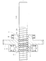
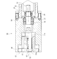
- FIG. 1 is a longitudinal sectional view showing an embodiment of an electric linear actuator according to the present invention. It is a longitudinal cross-sectional view which shows the ball screw mechanism of FIG.
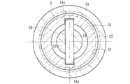
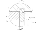
- FIG. 3 is a transverse sectional view taken along line III-III in FIG. It is a principal part enlarged view which shows the mounting part of the retaining ring of FIG.
- (A) is a side view of a retaining ring according to the present invention
- (b) is a front view of (a).
- a cylindrical housing made of an aluminum light alloy, an electric motor attached to the housing, a reduction mechanism that transmits the rotational force of the electric motor via a motor shaft, and rotation of the electric motor via the reduction mechanism
- a ball screw mechanism that converts the motion into a linear motion in the axial direction of the drive shaft, and this ball screw mechanism is supported via a pair of support bearings mounted on the housing so as to be rotatable and non-movable in the axial direction.
- a nut having a spiral thread groove formed on the inner periphery, and inserted into the nut via a number of balls, integrated coaxially with the drive shaft, and corresponding to the thread groove of the nut on the outer periphery.
- the screw shaft is formed so as to be non-rotatable with respect to the housing and supported so as to be movable in the axial direction, and the screw shaft is accommodated in the housing.
- a cylindrical sleeve is fitted into the housing hole of the housing, and the sleeve extends in the axial direction on the inner periphery of the sleeve, and a pair of concave grooves are formed at opposing positions.
- a guide pin implanted at the end of the screw shaft is engaged, and an annular groove is formed in the opening of the housing hole of the housing.
- the annular groove is attached to the annular groove and is symmetrical with respect to the notch.
- the sleeve is retained in a pressed state by a retaining ring for a hole in which a curved portion having a vertex is formed at a certain position.
- FIG. 1 is a longitudinal sectional view showing an embodiment of an electric linear actuator according to the present invention
- FIG. 2 is a longitudinal sectional view showing a ball screw mechanism of FIG. 1
- FIG. 3 is taken along the line III-III of FIG. 4 is an enlarged view of the main part showing the retaining ring mounting portion of FIG. 1
- FIG. 5A is a side view of the retaining ring according to the present invention
- FIG. FIG. 6 is a front view and FIG. 6 is an explanatory view showing a mounting portion state of a conventional retaining ring.
- the electric linear actuator 1 includes a cylindrical housing 2, an electric motor 3 attached to the housing 2, and a pair for transmitting the rotational force of the electric motor 3 via a motor shaft 3a. And a ball screw mechanism 8 for converting the rotational motion of the electric motor 3 into the linear motion of the drive shaft 7 via the speed reduction mechanism 6.
- the housing 2 is made of an aluminum alloy such as A6063TE or ADC12, and includes a first housing 2a and a second housing 2b abutted on the end face thereof, and is integrally fixed by a fixing bolt (not shown). Yes.
- An electric motor 3 is attached to the first housing 2a, and an accommodation hole (bag hole) 9 and an accommodation hole (penetration) for accommodating the screw shaft 12 are provided in the first housing 2a and the second housing 2b. Hole 10 is formed.
- a small spur gear 4 is attached to the end of the motor shaft 3a of the electric motor 3 so as not to be relatively rotatable by press fitting, and is rotatably supported by a rolling bearing 11 attached to the second housing 2b.
- the large spur gear 5 is integrally formed with a nut 14 constituting a ball screw mechanism 8 described later, and meshes with the small spur gear 4.
- the drive shaft 7 is configured integrally with a screw shaft 12 constituting the ball screw mechanism 8.
- the ball screw mechanism 8 includes a screw shaft 12 and a nut 14 that is externally mounted on the screw shaft 12 via a ball 13 as shown in an enlarged manner in FIG.
- the screw shaft 12 has a spiral thread groove 12a formed on the outer periphery thereof, and is supported so as to be movable in the axial direction and non-rotatable.
- the nut 14 is formed with a spiral thread groove 14a corresponding to the thread groove 12a of the screw shaft 12 on the inner periphery, and a large number of balls 13 are accommodated between the thread grooves 12a and 14a in a freely rolling manner. ing.
- the nut 14 is supported by a housing (not shown) via two support bearings 15 and 16 so as to be rotatable and not movable in the axial direction.
- Reference numeral 17 denotes a piece member that constitutes a circulation member for the ball 13 by connecting the thread groove 14 a of the nut 14, and a large number of balls 13 can be infinitely circulated by the piece member 17.
- each thread groove 12a, 14a may be a circular arc shape or a Gothic arc shape, but here, it has a Gothic arc shape that allows a large contact angle with the ball 13 and a small axial clearance. Is formed. Thereby, the rigidity with respect to an axial load becomes high and generation
- the nut 14 is made of case-hardened steel such as SCM415 or SCM420, and the surface thereof is hardened in the range of 55 to 62 HRC by vacuum carburizing and quenching. Thereby, the buffing etc. for the scale removal after the heat treatment can be omitted, and the cost can be reduced.
- the screw shaft 12 is made of medium carbon steel such as S55C or case-hardened steel such as SCM415 or SCM420, and its surface is hardened in the range of 55 to 62 HRC by induction hardening or carburizing hardening.
- a large spur gear 5 constituting the speed reduction mechanism 6 is integrally formed on the outer periphery of the nut 14, and two support bearings 15 and 16 are press-fitted on both sides of the large spur gear 5 via a predetermined squeeze.
- the two support bearings 15 and 16 are constituted by sealed deep groove ball bearings having shield plates attached to both ends thereof, leakage of lubricating grease sealed inside the bearing, wear powder from the outside, and the like. Is prevented from entering the inside of the bearing.
- a cylindrical sleeve 18 is fitted into the accommodation hole (bag hole) 9 of the first housing 2a.
- the sleeve 18 is made of a sintered alloy prepared by adjusting a metal powder into a plastic shape and molding it with an injection molding machine.
- first, metal powder and a binder made of plastic and wax are kneaded by a kneader, and the kneaded product is granulated into pellets.
- the granulated pellets are molded by so-called MIM (Metal Injection Molding), which is supplied to a hopper of an injection molding machine and pushed into a mold in a heated and melted state.
- MIM Metal Injection Molding
- C carbon
- Ni nickel
- Cr chromium
- Cu copper
- SCM415 which is 0.04 wt%
- Mn manganese
- Mo molecular weight
- Si silicon
- Si silicon
- the rest Fe (iron).
- the sleeve 18 is performed by adjusting the carburizing quenching and tempering temperatures.
- the material of the sleeve 18 includes 3.0 to 10.0 wt% of Ni and is excellent in workability and corrosion resistance (FEN8 of Japanese Powder Metallurgy Industry Standard), or C is 0.07 wt%. %, Cr is 17 wt%, Ni is 4 wt%, Cu is 4 wt%, and the remainder is precipitation hardened stainless steel SUS630 made of Fe or the like. This SUS630 can appropriately increase the surface hardness in the range of 20 to 33 HRC by solution heat treatment, and can ensure toughness and high hardness.
- the sleeve 18 is formed with a concave groove 18a extending in the axial direction so as to face the circumferential direction.
- the material strength and wear resistance are higher than those of the first housing 2a made of at least an aluminum alloy, and the durability can be improved.
- a through hole 19 penetrating in the radial direction is formed at the end of the screw shaft 12, and a guide pin 20 is fitted into the through hole 19.
- the sleeve 18 is press-fitted into the accommodation hole 9 of the housing 2a.
- An annular groove 21 is formed in the opening of the accommodation hole 9, and the sleeve 18 is positioned and fixed in the axial direction by a retaining ring 22 for a hole, which will be described later, attached to the annular groove 21 (see FIG. 1).
- the guide pin 20 is engaged with the concave groove 18a of the sleeve 18, and the rotation of the screw shaft 12 is prevented together with the guide in the axial direction.
- the guide pin 20 and the sleeve 18 having the concave groove 18 a that engages with the guide pin 20 constitute a rotation preventing mechanism for the screw shaft 12.
- the guide pin 20 uses a needle roller (needle) for a needle roller bearing that is excellent in wear resistance and shear strength and that is easily available and low in cost.
- needle roller needle roller bearing
- the edge load is prevented in contact with the concave groove 18a of the sleeve 18 to reduce the contact surface pressure, and for a long period of time. Durability can be improved.
- a retaining ring 22 is attached to an annular groove 21 formed in the accommodation hole 9, and the sleeve 18 interferes with the retaining ring 22, thereby causing the sleeve 18. Is prevented from moving in the axial direction.
- the retaining ring 22 is formed from a hard steel wire such as SWRH67A (JIS G3506).
- the retaining ring 22 is not flat like an ordinary C-shaped concentric retaining ring, but has an arcuate shape, that is, at least at a position symmetrical with respect to the notch 22a. Curved portions 23 and 23 having apexes at one place (here, one place at the center) are formed.
- the retaining ring 22 can be used, for example, by pressing from an austenitic stainless steel plate (JIS standard SUS304 type or the like) or a rust-proof cold rolled steel plate (JIS standard SPCC type or the like). It may be formed.
- an austenitic stainless steel plate JIS standard SUS304 type or the like
- a rust-proof cold rolled steel plate JIS standard SPCC type or the like
- the axial direction depends on the backlash ⁇ 1 (axial clearance) between the annular groove 21 and the retaining ring 24 or the backlash ⁇ 2 between the retaining ring 24 and the sleeve 18. Further, there is a risk that the sleeve 18 will rattle, and the housing hole 9 of the housing 2b may be worn, sounded or vibrated. Further, when the retaining ring 24 is mounted, the inner diameter of the receiving hole 9 is scraped because the diameter of the retaining hole 9 is increased while entering the annular groove 21 while being in contact with the inner peripheral face of the receiving hole 9. If this shaving powder remains in the actuator as contamination, it may cause malfunction, which is not preferable.
- the edge of the outer diameter portion of the retaining ring 22 is removed and rounded.
- the groove width W of the annular groove 21 is set to be smaller than the free height H0 of the retaining ring 22 (see FIG. 5A)
- the annular groove 21 is annular with respect to the uncompressed state (free height H0). In the state where it is mounted in the groove 21 (mounting height H1), it is compressed in the axial direction.
- an axial load is generated on the sleeve 18 by the spring force of the retaining ring 22, and a predetermined preload can be applied to the sleeve 18 to reliably prevent the housing 2b from being worn, sounded or vibrated. be able to.
- An electric linear actuator according to the present invention is used in a drive unit of a general industrial electric motor, automobile, etc., and has a ball screw mechanism that converts rotational input from an electric motor into linear motion of a drive shaft via the ball screw mechanism. It can be applied to the provided electric linear actuator.
Abstract
【課題】摺動摩擦や摩耗の低減を図ると共に、簡便な構造で低コスト化を図った電動リニアアクチュエータを提供する。 【解決手段】減速機構6を介して電動モータ3の回転運動を駆動軸7の軸方向の直線運動に変換するボールねじ機構8を備えた電動リニアアクチュエータにおいて、ハウジング2aの収容孔9に円筒状のスリーブ18が嵌合され、このスリーブ18の内周に軸方向に延び、対向する位置に一対の凹溝18aが形成されてねじ軸12の端部に植設されたガイドピン20が係合されると共に、ハウジング2aの収容孔9の開口部に環状溝21が形成され、この環状溝21に装着され、切欠き部を中心に左右対称となる位置に頂点を有する湾曲部が形成された穴用の止め輪22によってスリーブ18が押圧された状態で抜け止めされている。
Description
本発明は、一般産業用の電動機、自動車等の駆動部に使用されるボールねじ機構を備えた電動リニアアクチュエータ、詳しくは、自動車のトランスミッションやパーキングブレーキ等で、電動モータからの回転入力を、ボールねじ機構を介して駆動軸の直線運動に変換する電動リニアアクチュエータに関するものである。
各種駆動部に使用される電動リニアアクチュエータにおいて、電動モータの回転運動を軸方向の直線運動に変換する機構として、台形ねじ、あるいはラックアンドピニオン等の歯車機構が一般的に使用されている。これらの変換機構は、滑り接触部を伴うため動力損失が大きく、電動モータの大型化や消費電力の増大を余儀なくされている。そのため、より効率的なアクチュエータとしてボールねじ機構が採用されるようになってきた。
従来の電動リニアアクチュエータとしては、例えば、ハウジングに支持された電動モータにより、ボールねじを構成するボールねじ軸を回転駆動自在とし、このボールねじ軸を回転駆動することによってナットに結合された出力部材を軸方向に変位可能としている。ボールねじ機構は、摩擦が非常に低く、出力部材側に作用するスラスト荷重によって簡単にボールねじ軸が回転してしまうので、電動モータが停止時に出力部材を位置保持する必要がある。
そこで、例えば、電動モータにブレーキ手段を設けたり、あるいは伝達手段としてウォームギアのような低効率なものを設けたりすることがなされているが、その代表的なものとして、図7に示すような電動リニアアクチュエータが知られている。この電動リニアアクチュエータ50は、電動モータ(図示せず)により回転駆動されるボールねじ軸51と、このボールねじ軸51にボール(図示せず)を介して螺合されたボールねじナット52とを備えるボールねじ機構53を採用している。電動モータのモータ軸(図示せず)が回転すると、このモータ軸に連結されたボールねじ軸51が回転し、ボールねじナット52を直線運動(図の左右方向)に移動させる。
ボールねじ軸51は、円筒状のハウジング54、55に2つの転がり軸受56、57によって回転自在に支承されている。これらの転がり軸受56、57は、固定用の蓋58を介して緩み止め用の回り止め部材59によって固定されている。
ボールねじ軸51の外周には螺旋状のねじ溝51aが形成され、ボールを介して円筒状のボールねじナット52が螺合されている。ボールねじナット52の内周には螺旋状のねじ溝52aが形成され、端部に大径部60が形成されている。
大径部60の側面には、端面がフラットになるようにカットされたフラット部61が形成されている。このフラット部61の略中央部には、カムフォロア(回転止め手段)62が径方向の外側に向けて突設されている。
このように、カムフォロア62が切欠き部に嵌合されているので、ボールねじナット52は、ボールねじ軸51の回転に伴って連れ回りすることがなく、かつ、カムフォロア62が切欠き部に回転摺動するので、摺動摩擦や摩耗の問題を低減することができる(例えば、特許文献1参照。)。
こうした従来の電動リニアアクチュエータ50では、ボールねじナット52の回転止め手段としてカムフォロア62が使用されているため、摺動摩擦や摩耗の問題を低減すると共に、低トルク化を図ることができるが、カムフォロア62自体が転がり軸受を使用しているためコストが高騰する恐れがある。また、ハウジング54がアルミ材料を使用している場合は、摩耗対策が必要になってくる。
本発明は、こうした従来技術の問題点に鑑みてなされたものであり、摺動摩擦や摩耗の低減を図ると共に、簡便な構造で低コスト化を図った電動リニアアクチュエータを提供することを目的とする。
係る目的を達成すべく、本発明のうち請求項1に記載の発明は、アルミ軽合金からなる円筒状のハウジングと、このハウジングに取り付けられた電動モータと、この電動モータの回転力をモータ軸を介して伝達する減速機構と、この減速機構を介して前記電動モータの回転運動を駆動軸の軸方向の直線運動に変換するボールねじ機構とを備え、このボールねじ機構が、前記ハウジングに装着された一対の支持軸受を介して回転可能に、かつ軸方向移動不可に支持され、内周に螺旋状のねじ溝が形成されたナットと、このナットに多数のボールを介して内挿され、前記駆動軸と同軸状に一体化され、外周に前記ナットのねじ溝に対応する螺旋状のねじ溝が形成され、前記ハウジングに対して回転不可に、かつ軸方向移動可能に支持されたねじ軸とで構成されると共に、前記ハウジングに前記ねじ軸を収容する収容孔が形成された電動リニアアクチュエータにおいて、前記ハウジングの収容孔に円筒状のスリーブが嵌合され、このスリーブの内周に軸方向に延び、対向する位置に一対の凹溝が形成されて前記ねじ軸の端部に植設されたガイドピンが係合されると共に、前記ハウジングの収容孔の開口部に環状溝が形成され、この環状溝に装着された穴用の止め輪によって前記スリーブが押圧された状態で抜け止めされている。
このように、アルミ軽合金からなる円筒状のハウジングと、このハウジングに取り付けられた電動モータと、この電動モータの回転力をモータ軸を介して伝達する減速機構と、この減速機構を介して電動モータの回転運動を駆動軸の軸方向の直線運動に変換するボールねじ機構とを備え、このボールねじ機構が、ハウジングに装着された一対の支持軸受を介して回転可能に、かつ軸方向移動不可に支持され、内周に螺旋状のねじ溝が形成されたナットと、このナットに多数のボールを介して内挿され、駆動軸と同軸状に一体化され、外周にナットのねじ溝に対応する螺旋状のねじ溝が形成され、ハウジングに対して回転不可に、かつ軸方向移動可能に支持されたねじ軸とで構成されると共に、ハウジングにねじ軸を収容する収容孔が形成された電動リニアアクチュエータにおいて、ハウジングの収容孔に円筒状のスリーブが嵌合され、このスリーブの内周に軸方向に延び、対向する位置に一対の凹溝が形成されてねじ軸の端部に植設されたガイドピンが係合されると共に、ハウジングの収容孔の開口部に環状溝が形成され、この環状溝に装着された穴用の止め輪によってスリーブが押圧された状態で抜け止めされているので、ハウジングの摺動摩擦や摩耗の低減を図ると共に、簡便な構造で低コスト化を図った電動リニアアクチュエータを提供することができる。
好ましくは、請求項2に記載の発明のように、前記止め輪が、切欠き部を中心に左右対称となる位置に少なくとも一箇所に頂点を有する湾曲部が形成されていれば、止め輪のばね力によって軸方向荷重が発生し、スリーブに所定の予圧を付与することができ、ハウジングの摩耗や音あるいは振動の発生を確実に防止することができる。
また、請求項3に記載の発明のように、前記環状溝の溝幅が前記止め輪の自由高さよりも小さく設定されていれば、圧縮されていない状態に対し、環状溝に装着された状態では軸方向に圧縮され、止め輪に軸方向荷重が発生する。
また、請求項4に記載の発明のように、前記止め輪の少なくとも外径部の角部が丸められていれば、装着時にハウジングに接触し、内周面を削ってコンタミの発生による作動不良を防止して信頼性を高めることができる。
また、請求項5に記載の発明のように、前記止め輪が、予め角部が丸められた線材を用いてプレス加工によって形成されていれば、後処理が不要となり量産性が向上する。
また、請求項6に記載の発明のように、前記スリーブが、浸炭焼入が可能な焼結合金で形成されていれば、加工度が高く複雑な形状であっても容易に、かつ精度良く所望の形状・寸法に成形することができる。
また、請求項7に記載の発明のように、前記ハウジングがアルミダイカストによって形成されていれば、量産性に富み、低コスト化を図ることができる。
また、請求項8に記載の発明のように、前記ガイドピンが針状ころ軸受用の針状ころからなっていれば、耐摩耗性とせん断強度に優れると共に、入手性が良く低コスト化を図ることができる。また、針状ころを使用することにより、外周面にクラウニングが形成されているので、スリーブの凹溝との接触においてエッジロードを防止して接触面圧を低下させ、長期間に亘って耐久性を向上させることができる。
本発明に係る電動リニアアクチュエータは、アルミ軽合金からなる円筒状のハウジングと、このハウジングに取り付けられた電動モータと、この電動モータの回転力をモータ軸を介して伝達する減速機構と、この減速機構を介して前記電動モータの回転運動を駆動軸の軸方向の直線運動に変換するボールねじ機構とを備え、このボールねじ機構が、前記ハウジングに装着された一対の支持軸受を介して回転可能に、かつ軸方向移動不可に支持され、内周に螺旋状のねじ溝が形成されたナットと、このナットに多数のボールを介して内挿され、前記駆動軸と同軸状に一体化され、外周に前記ナットのねじ溝に対応する螺旋状のねじ溝が形成され、前記ハウジングに対して回転不可に、かつ軸方向移動可能に支持されたねじ軸とで構成されると共に、前記ハウジングに前記ねじ軸を収容する収容孔が形成された電動リニアアクチュエータにおいて、前記ハウジングの収容孔に円筒状のスリーブが嵌合され、このスリーブの内周に軸方向に延び、対向する位置に一対の凹溝が形成されて前記ねじ軸の端部に植設されたガイドピンが係合されると共に、前記ハウジングの収容孔の開口部に環状溝が形成され、この環状溝に装着された穴用の止め輪によって前記スリーブが押圧された状態で抜け止めされているので、ハウジングの摺動摩擦や摩耗の低減を図ると共に、簡便な構造で低コスト化を図った電動リニアアクチュエータを提供することができる。
アルミ軽合金からなる円筒状のハウジングと、このハウジングに取り付けられた電動モータと、この電動モータの回転力をモータ軸を介して伝達する減速機構と、この減速機構を介して前記電動モータの回転運動を駆動軸の軸方向の直線運動に変換するボールねじ機構とを備え、このボールねじ機構が、前記ハウジングに装着された一対の支持軸受を介して回転可能に、かつ軸方向移動不可に支持され、内周に螺旋状のねじ溝が形成されたナットと、このナットに多数のボールを介して内挿され、前記駆動軸と同軸状に一体化され、外周に前記ナットのねじ溝に対応する螺旋状のねじ溝が形成され、前記ハウジングに対して回転不可に、かつ軸方向移動可能に支持されたねじ軸とで構成されると共に、前記ハウジングに前記ねじ軸を収容する収容孔が形成された電動リニアアクチュエータにおいて、前記ハウジングの収容孔に円筒状のスリーブが嵌合され、このスリーブの内周に軸方向に延び、対向する位置に一対の凹溝が形成されて前記ねじ軸の端部に植設されたガイドピンが係合されると共に、前記ハウジングの収容孔の開口部に環状溝が形成され、この環状溝に装着され、切欠き部を中心に左右対称となる位置に頂点を有する湾曲部が形成された穴用の止め輪によって前記スリーブが押圧された状態で抜け止めされている。
以下、本発明の実施の形態を図面に基づいて詳細に説明する。
図1は、本発明に係る電動リニアアクチュエータの一実施形態を示す縦断面図、図2は、図1のボールねじ機構を示す縦断面図、図3は、図1のIII-III線に沿った横断面図、図4は、図1の止め輪の装着部を示す要部拡大図、図5(a)は、本発明に係る止め輪の側面図、(b)は、(a)の正面図、図6は、従来の止め輪の装着部状態を示す説明図である。
図1は、本発明に係る電動リニアアクチュエータの一実施形態を示す縦断面図、図2は、図1のボールねじ機構を示す縦断面図、図3は、図1のIII-III線に沿った横断面図、図4は、図1の止め輪の装着部を示す要部拡大図、図5(a)は、本発明に係る止め輪の側面図、(b)は、(a)の正面図、図6は、従来の止め輪の装着部状態を示す説明図である。
この電動リニアアクチュエータ1は、図1に示すように、円筒状のハウジング2と、このハウジング2に取り付けられた電動モータ3と、この電動モータ3の回転力をモータ軸3aを介して伝達する一対の平歯車4、5からなる減速機構6と、この減速機構6を介して電動モータ3の回転運動を駆動軸7の軸方向の直線運動に変換するボールねじ機構8とを備えている。
ハウジング2は、A6063TEやADC12等のアルミ合金からなり、第1のハウジング2aと、その端面に衝合された第2のハウジング2bとを備え、固定ボルト(図示せず)によって一体に固定されている。第1のハウジング2aには電動モータ3が取り付けられると共に、この第1のハウジング2aと第2のハウジング2bには、ねじ軸12を収容するための収容孔(袋孔)9と収容孔(貫通孔)10がそれぞれ形成されている。
電動モータ3のモータ軸3aの端部には小平歯車4が圧入により相対回転不能に取り付けられ、第2のハウジング2bに装着された転がり軸受11によって回転自在に支持されている。大平歯車5は、後述するボールねじ機構8を構成するナット14に一体形成され、小平歯車4に噛合している。駆動軸7は、ボールねじ機構8を構成するねじ軸12と一体に構成されている。
ボールねじ機構8は、図2に拡大して示すように、ねじ軸12と、このねじ軸12にボール13を介して外装されたナット14とを備えている。ねじ軸12は、外周に螺旋状のねじ溝12aが形成され、軸方向移動自在に、かつ回転不可に支承されている。一方、ナット14は、内周にねじ軸12のねじ溝12aに対応する螺旋状のねじ溝14aが形成され、これらねじ溝12a、14aとの間に多数のボール13が転動自在に収容されている。そして、ナット14は、ハウジング(図示せず)に対して、2つの支持軸受15、16を介して回転自在に、かつ軸方向移動不可に支承されている。17は、ナット14のねじ溝14aを連結してボール13の循環部材を構成する駒部材で、この駒部材17によって多数のボール13が無限循環することができる。
各ねじ溝12a、14aの断面形状は、サーキュラアーク形状であってもゴシックアーク形状であっても良いが、ここではボール13との接触角が大きくとれ、アキシアルすきまが小さく設定できるゴシックアーク形状に形成されている。これにより、軸方向荷重に対する剛性が高くなり、かつ振動の発生を抑制することができる。
ナット14はSCM415やSCM420等の肌焼き鋼からなり、真空浸炭焼入れによってその表面に55~62HRCの範囲に硬化処理が施されている。これにより、熱処理後のスケール除去のためのバフ加工等を省略することができ、低コスト化を図ることができる。一方、ねじ軸12はS55C等の中炭素鋼あるいはSCM415やSCM420等の肌焼き鋼からなり、高周波焼入れ、あるいは浸炭焼入れによってその表面に55~62HRCの範囲に硬化処理が施されている。
ナット14の外周には減速機構6を構成する大平歯車5が一体に形成されると共に、この大平歯車5の両側に2つの支持軸受15、16が所定のシメシロを介して圧入されている。これにより、駆動軸7からスラスト荷重が負荷されても支持軸受15、16と大平歯車5の軸方向の位置ズレを防止することができる。また、2つの支持軸受15、16は、両端部にシールド板が装着された密封型の深溝玉軸受で構成され、軸受内部に封入された潤滑グリースの外部への漏洩と、外部から摩耗粉等が軸受内部に侵入するのを防止している。
ここで、本実施形態では、図1に示すように、第1のハウジング2aの収容孔(袋孔)9に筒状のスリーブ18が嵌合されている。このスリーブ18は、金属粉末を可塑状に調整し、射出成形機で成形される焼結合金からなる。この射出成形に際しては、まず、金属粉と、プラスチックおよびワックスからなるバインダとを混練機で混練し、その混練物をペレット状に造粒する。造粒したペレットは、射出成形機のホッパに供給し、金型内に加熱溶融状態で押し込む、所謂MIM(Metal Injection Molding)により成形されている。こうしたMIMによって成形される焼結合金であれば、加工度が高く複雑な形状であっても容易に、かつ精度良く所望の形状・寸法に成形することができる。
前記金属粉として、後に浸炭焼入が可能な材質、例えば、C(炭素)が0.13wt%、Ni(ニッケル)が0.21wt%、Cr(クロム)が1.1wt%、Cu(銅)が0.04wt%、Mn(マンガン)が0.76wt%、Mo(モリブデン)が0.19wt%、Si(シリコン)が0.20wt%、残りがFe(鉄)等からなるSCM415を例示することができる。スリーブ18は、浸炭焼入れおよび焼戻し温度を調整して行われる。また、スリーブ18の材料としてこれ以外にも、Niが3.0~10.0wt%含有し、加工性、耐食性に優れた材料(日本粉末冶金工業規格のFEN8)、あるいは、Cが0.07wt%、Crが17wt%、Niが4wt%、Cuが4wt%、残りがFe等からなる析出硬化系ステンレスSUS630であっても良い。このSUS630は、固溶化熱処理で20~33HRCの範囲に表面硬さを適切に上げることができ、強靭性と高硬度を確保することができる。
スリーブ18は、図3に示すように、周方向に対向して軸方向に延びる凹溝18aが成形されている。このような材料を採用することにより、少なくともアルミ合金からなる第1のハウジング2aよりも材料強度と耐摩耗性が高くなり、耐久性を向上させることができる。
一方、ねじ軸12の端部には径方向に貫通する貫通孔19が形成され、この貫通孔19にガイドピン20が嵌着されている。また、スリーブ18は、ハウジング2aの収容孔9に圧入されている。収容孔9の開口部には環状溝21が形成され、この環状溝21に装着された後述する穴用の止め輪22によってスリーブ18が軸方向に位置決め固定されている(図1参照)。
ここで、ガイドピン20がスリーブ18の凹溝18aに係合し、ねじ軸12の軸方向の案内と共に回り止めを行う。このガイドピン20と、このガイドピン20に係合する凹溝18aを有するスリーブ18とでねじ軸12の回り止め機構を構成している。
ガイドピン20には、耐摩耗性とせん断強度に優れると共に、入手性が良く低コストな針状ころ軸受用の針状ころ(ニードル)が使用されている。特に、針状ころを使用することにより、外周面にクラウニングが形成されているので、スリーブ18の凹溝18aとの接触においてエッジロードを防止して接触面圧を低下させ、長期間に亘って耐久性を向上させることができる。
このように、ねじ軸12のガイドピン20がスリーブ18の凹溝18aに係合し、ねじ軸12の軸方向の案内と共に回り止めを行うため、アルミ軽合金からなるハウジング2aの摺動摩擦や摩耗の低減を図ると共に、簡便な構造で低コスト化を図った電動リニアアクチュエータを提供することができる。
ここで、本実施形態では、図4に拡大して示すように、収容孔9に形成された環状溝21に止め輪22が装着され、この止め輪22にスリーブ18が干渉することによってスリーブ18の軸方向の移動が阻止されている。止め輪22は、SWRH67A(JIS G3506)等の硬鋼線材から形成されている。そして、図5に示すように、この止め輪22は、通常のC形同心止め輪のように端面が平坦ではなく、弓形形状、すなわち、切欠き部22aを中心に左右対称となる位置に少なくとも一箇所(ここでは、中央部に一箇所)に頂点を有する湾曲部23、23が形成されている。
なお、止め輪22は、前述したもの以外に、例えば、オーステナイト系ステンレス鋼板(JIS規格のSUS304系等)、あるいは防錆処理された冷間圧延鋼板(JIS規格のSPCC系等)からプレス加工にて形成されていても良い。
図6に比較して示すように、従来の止め輪24では、環状溝21と止め輪24とのガタδ1(軸方向すきま)、あるいは、止め輪24とスリーブ18とのガタδ2より、軸方向にスリーブ18がガタつき、ハウジング2bの収容孔9の摩耗や、音あるいは振動が発生する恐れがある。また、止め輪24の装着時に、縮径した状態で収容孔9の内周面と接触しながら環状溝21に拡径して入るため、収容孔9の内周面を削ってしまう。この削り粉はコンタミとしてアクチュエータ内部に残留した場合、作動不良の原因となる恐れがあって好ましくない。
これに対し、本実施形態では、図4に示すように、少なくとも止め輪22の外径部の角部のエッジが除去され丸められている。なお、予め角部が丸められた線材を用いてプレス加工によって形成されていれば、後処理が不要となり量産性が向上する。また、環状溝21の溝幅Wが止め輪22の自由高さH0(図5(a)参照)よりも小さく設定されているため、圧縮されていない状態(自由高さH0)に対し、環状溝21に装着された状態(装着高さH1)では軸方向に圧縮される。すなわち、スリーブ18に対して、止め輪22のばね力によって軸方向荷重が発生し、スリーブ18に所定の予圧を付与することができ、ハウジング2bの摩耗や音あるいは振動の発生を確実に防止することができる。
以上、本発明の実施の形態について説明を行ったが、本発明はこうした実施の形態に何等限定されるものではなく、あくまで例示であって、本発明の要旨を逸脱しない範囲内において、さらに種々なる形態で実施し得ることは勿論のことであり、本発明の範囲は、特許請求の範囲の記載によって示され、さらに特許請求の範囲に記載の均等の意味、および範囲内のすべての変更を含む。
本発明に係る電動リニアアクチュエータは、一般産業用の電動機、自動車等の駆動部に使用され、電動モータからの回転入力を、ボールねじ機構を介して駆動軸の直線運動に変換するボールねじ機構を備えた電動リニアアクチュエータに適用できる。
1 電動リニアアクチュエータ
2 ハウジング
2a 第1のハウジング
2b 第2のハウジング
3 電動モータ
3a モータ軸
4 小平歯車
5 大平歯車
6 減速機構
7 駆動軸
8 ボールねじ機構
9 収容孔(袋孔)
10 収容孔(貫通孔)
11 転がり軸受
12 ねじ軸
12a、14a ねじ溝
13 ボール
14 ナット
15、16 支持軸受
17 駒部材
18 スリーブ
18a 凹溝
19 貫通孔
20 ガイドピン
21 環状溝
22、24 止め輪
22a 切欠き部
23 湾曲部
50 電動リニアアクチュエータ
51 ボールねじ軸
51a、52a ねじ溝
52 ボールねじナット
53 ボールねじ
54、55 ハウジング
56、57 転がり軸受
58 固定用の蓋
59 緩み止め用の回り止め部材
60 ナットの大径部
61 フラット部
H0 止め輪の自由高さ
H1 止め輪の装着高さ
W 環状溝の溝幅
δ1 止め輪と環状溝とのガタ
δ2 止め輪とスリーブとのガタ
Claims (8)
- アルミ軽合金からなる円筒状のハウジングと、
このハウジングに取り付けられた電動モータと、
この電動モータの回転力をモータ軸を介して伝達する減速機構と、
この減速機構を介して前記電動モータの回転運動を駆動軸の軸方向の直線運動に変換するボールねじ機構とを備え、
このボールねじ機構が、前記ハウジングに装着された一対の支持軸受を介して回転可能に、かつ軸方向移動不可に支持され、内周に螺旋状のねじ溝が形成されたナットと、
このナットに多数のボールを介して内挿され、前記駆動軸と同軸状に一体化され、外周に前記ナットのねじ溝に対応する螺旋状のねじ溝が形成され、前記ハウジングに対して回転不可に、かつ軸方向移動可能に支持されたねじ軸とで構成されると共に、
前記ハウジングに前記ねじ軸を収容する収容孔が形成された電動リニアアクチュエータにおいて、
前記ハウジングの収容孔に円筒状のスリーブが嵌合され、このスリーブの内周に軸方向に延び、対向する位置に一対の凹溝が形成されて前記ねじ軸の端部に植設されたガイドピンが係合されると共に、前記ハウジングの収容孔の開口部に環状溝が形成され、この環状溝に装着された穴用の止め輪によって前記スリーブが押圧された状態で抜け止めされていることを特徴とする電動リニアアクチュエータ。 - 前記止め輪が、切欠き部を中心に左右対称となる位置に少なくとも一箇所に頂点を有する湾曲部が形成されている請求項1に記載の電動リニアアクチュエータ。
- 前記環状溝の溝幅が前記止め輪の自由高さよりも小さく設定されている請求項1または2に記載の電動リニアアクチュエータ。
- 前記止め輪の少なくとも外径部の角部が丸められている請求項1乃至3いずれかに記載の電動リニアアクチュエータ。
- 前記止め輪が、予め角部が丸められた線材を用いてプレス加工によって形成されている請求項1乃至4いずれかに記載の電動リニアアクチュエータ。
- 前記スリーブが、浸炭焼入が可能な焼結合金で形成されている請求項1に記載の電動リニアアクチュエータ。
- 前記ハウジングがアルミダイカストによって形成されている請求項1に記載の電動リニアアクチュエータ。
- 前記ガイドピンが針状ころ軸受用の針状ころからなっている請求項1に記載の電動リニアアクチュエータ。
Priority Applications (3)
| Application Number | Priority Date | Filing Date | Title |
|---|---|---|---|
| EP13749561.0A EP2816254B1 (en) | 2012-02-17 | 2013-02-14 | Electric linear actuator |
| CN201380009606.5A CN104160176B (zh) | 2012-02-17 | 2013-02-14 | 电动线性致动器 |
| US14/461,367 US9574648B2 (en) | 2012-02-17 | 2014-08-16 | Electric linear actuator |
Applications Claiming Priority (2)
| Application Number | Priority Date | Filing Date | Title |
|---|---|---|---|
| JP2012-032234 | 2012-02-17 | ||
| JP2012032234A JP5914031B2 (ja) | 2012-02-17 | 2012-02-17 | 電動リニアアクチュエータ |
Related Child Applications (1)
| Application Number | Title | Priority Date | Filing Date |
|---|---|---|---|
| US14/461,367 Continuation US9574648B2 (en) | 2012-02-17 | 2014-08-16 | Electric linear actuator |
Publications (1)
| Publication Number | Publication Date |
|---|---|
| WO2013122158A1 true WO2013122158A1 (ja) | 2013-08-22 |
Family
ID=48984267
Family Applications (1)
| Application Number | Title | Priority Date | Filing Date |
|---|---|---|---|
| PCT/JP2013/053554 WO2013122158A1 (ja) | 2012-02-17 | 2013-02-14 | 電動リニアアクチュエータ |
Country Status (5)
| Country | Link |
|---|---|
| US (1) | US9574648B2 (ja) |
| EP (1) | EP2816254B1 (ja) |
| JP (1) | JP5914031B2 (ja) |
| CN (1) | CN104160176B (ja) |
| WO (1) | WO2013122158A1 (ja) |
Cited By (3)
| Publication number | Priority date | Publication date | Assignee | Title |
|---|---|---|---|---|
| US20170350479A1 (en) * | 2015-02-02 | 2017-12-07 | Ntn Corporation | Electric Actuator |
| TWI649956B (zh) * | 2017-10-19 | 2019-02-01 | 國立成功大學 | 線性串聯彈性致動器 |
| US10731743B2 (en) | 2011-11-16 | 2020-08-04 | Roller Bearing Company Of America, Inc. | Cam follower and yoke roller assemblies |
Families Citing this family (24)
| Publication number | Priority date | Publication date | Assignee | Title |
|---|---|---|---|---|
| KR101520922B1 (ko) * | 2013-11-13 | 2015-05-18 | 유도스타자동화 주식회사 | 사출성형기의 밸브 모터장치 |
| FR3028714B1 (fr) * | 2014-11-25 | 2017-03-31 | Pellenc Sa | Mecanisme de vis et ecrou a billes. |
| JP6524763B2 (ja) * | 2015-04-03 | 2019-06-05 | 日本精工株式会社 | ボールねじ機構及びアクチュエータ |
| CN104879463A (zh) * | 2015-05-05 | 2015-09-02 | 四川大学 | 一种使丝杠沿轴向方向运动的齿轮及其运动机构 |
| CN107035836A (zh) * | 2015-08-04 | 2017-08-11 | 日本电产三协电子(东莞)有限公司 | 线性致动器 |
| US9802640B2 (en) * | 2015-09-25 | 2017-10-31 | Steering Solutions Ip Holding Corporation | Ball screw assembly |
| JP6641881B2 (ja) * | 2015-10-23 | 2020-02-05 | 株式会社アドヴィックス | 車両用ブレーキ |
| JP6779645B2 (ja) * | 2016-03-30 | 2020-11-04 | Ntn株式会社 | 電動アクチュエータ |
| KR101691207B1 (ko) * | 2016-07-12 | 2016-12-29 | (주)에스엠디에스피 | 운동변환장치 및 이를 갖는 모바일 모듈 |
| DE102016213865A1 (de) * | 2016-07-28 | 2018-02-01 | Robert Bosch Gmbh | Antriebseinrichtung für einen Komfortantrieb eines Kraftfahrzeugs und Komfortantrieb |
| CN107795653B (zh) * | 2016-08-30 | 2020-03-17 | 上银科技股份有限公司 | 装设在义肢内的线性驱动系统 |
| DK3372869T3 (da) * | 2017-03-07 | 2022-01-17 | Fischer Georg Jrg Ag | Servodrevaktuator |
| CN107606089B (zh) * | 2017-08-21 | 2019-07-12 | 北京精密机电控制设备研究所 | 一种嵌套式滚珠丝杠副 |
| TWI657208B (zh) * | 2018-05-24 | 2019-04-21 | 高明鐵企業股份有限公司 | 電動缸 |
| CN109340461B (zh) * | 2018-09-25 | 2021-07-13 | 安徽科恩新能源有限公司 | 一种新式蒸汽管道隔热支架 |
| KR20200122537A (ko) * | 2019-04-18 | 2020-10-28 | 현대모비스 주식회사 | 차량용 전동부스터 |
| CN110131327B (zh) * | 2019-05-29 | 2021-06-22 | 浙江吉利控股集团有限公司 | 一种汽车离合器的螺旋式致动器 |
| JP7158785B2 (ja) * | 2019-06-28 | 2022-10-24 | 株式会社不二工機 | 流路構造、これを備えた逆止弁、及び逆止弁の製造方法 |
| CN110509908A (zh) * | 2019-08-01 | 2019-11-29 | 东风汽车集团有限公司 | 用于自动驾驶汽车的电子制动助力器、系统及方法 |
| US11836018B2 (en) | 2020-03-19 | 2023-12-05 | Canrig Robotic Technologies As | Robotic system including an internal cooling system |
| US11719044B2 (en) | 2020-03-19 | 2023-08-08 | Canrig Robotic Technologies As | Robotic system including an electrical clamping system |
| WO2022099490A1 (zh) * | 2020-11-11 | 2022-05-19 | 张贤良 | 一种电机驱动的直线运动装置 |
| TWI796627B (zh) * | 2021-01-11 | 2023-03-21 | 捷世達企業股份有限公司 | 線性致動器及線性致動器組裝方法 |
| CN114763827A (zh) | 2021-01-11 | 2022-07-19 | 捷世达企业股份有限公司 | 线性致动器及线性致动器组装方法 |
Citations (8)
| Publication number | Priority date | Publication date | Assignee | Title |
|---|---|---|---|---|
| JPH0849782A (ja) * | 1994-08-06 | 1996-02-20 | Toyota Autom Loom Works Ltd | 直動変換モータのスクリューシャフトの回り止め機構 |
| JPH08324982A (ja) * | 1995-06-06 | 1996-12-10 | Nippon Seiko Kk | ボールねじ式ジャッキ |
| JPH10331836A (ja) * | 1997-06-02 | 1998-12-15 | Nissan Motor Co Ltd | ガスステーの継手構造 |
| JP2005291480A (ja) * | 2004-04-06 | 2005-10-20 | Nsk Ltd | 電動式リニアアクチュエータ |
| JP2006316923A (ja) * | 2005-05-13 | 2006-11-24 | Chubu Bearing Kk | 軸用止め輪 |
| JP2007333046A (ja) * | 2006-06-14 | 2007-12-27 | Ntn Corp | 電動アクチュエータ |
| JP2010286083A (ja) * | 2009-06-15 | 2010-12-24 | Ntn Corp | 電動アクチュエータ |
| JP2012021609A (ja) * | 2010-07-15 | 2012-02-02 | Nsk Ltd | リニアアクチュエータ |
Family Cites Families (16)
| Publication number | Priority date | Publication date | Assignee | Title |
|---|---|---|---|---|
| US2487802A (en) * | 1944-11-08 | 1949-11-15 | Waldes Kohinoor Inc | Retaining ring assembly |
| US4752178A (en) * | 1986-12-17 | 1988-06-21 | Smalley Steel Ring Company | Waved retaining ring |
| US5046376A (en) * | 1991-04-03 | 1991-09-10 | Cooper Industries, Inc. | Shaft locking or manual operating apparatus |
| KR960008139A (ko) | 1994-08-06 | 1996-03-22 | 직동 변환 모터의 스크류 샤프트의 회전 방지 및 분리 방지 기구 | |
| US5899114A (en) * | 1997-08-14 | 1999-05-04 | Thomson Saginaw Ball Screw Company, L.L.C. | Differential ball screw and nut assembly and method of obtaining relative linear motion differentially |
| JP2001124170A (ja) * | 1999-10-27 | 2001-05-08 | Alpha Getriebe Ltd | リニアアクチュエータの支持点設置方式 |
| FR2809464B1 (fr) * | 2000-05-26 | 2002-10-11 | Commissariat Energie Atomique | Transmission a vis, ecrou et cable attache a la vis |
| JP2002122203A (ja) * | 2000-10-17 | 2002-04-26 | Minebea Co Ltd | リニアアクチュエータ |
| ITTO20060110A1 (it) * | 2006-02-16 | 2007-08-17 | Skf Ab | Attuatore elettromeccanico lineare per un freno di stazionamento. |
| JP5340561B2 (ja) * | 2007-06-15 | 2013-11-13 | Ntn株式会社 | 円すいころ軸受 |
| JP5243018B2 (ja) * | 2007-12-27 | 2013-07-24 | Ntn株式会社 | 電動リニアアクチュエータ |
| DE102008051544B4 (de) * | 2008-10-14 | 2012-12-27 | Continental Automotive Gmbh | Spindeltrieb mit Verdrehsicherung |
| TWM356733U (en) * | 2008-12-05 | 2009-05-11 | Moteck Electric Corp | Push rod structure |
| JP2011117513A (ja) * | 2009-12-02 | 2011-06-16 | Ntn Corp | 電動アクチュエータ |
| JP5293887B2 (ja) * | 2010-04-26 | 2013-09-18 | 日本精工株式会社 | 直動アクチュエータ |
| JP5547563B2 (ja) * | 2010-06-25 | 2014-07-16 | Ntn株式会社 | 電動アクチュエータ |
-
2012
- 2012-02-17 JP JP2012032234A patent/JP5914031B2/ja active Active
-
2013
- 2013-02-14 EP EP13749561.0A patent/EP2816254B1/en active Active
- 2013-02-14 CN CN201380009606.5A patent/CN104160176B/zh active Active
- 2013-02-14 WO PCT/JP2013/053554 patent/WO2013122158A1/ja active Application Filing
-
2014
- 2014-08-16 US US14/461,367 patent/US9574648B2/en active Active
Patent Citations (8)
| Publication number | Priority date | Publication date | Assignee | Title |
|---|---|---|---|---|
| JPH0849782A (ja) * | 1994-08-06 | 1996-02-20 | Toyota Autom Loom Works Ltd | 直動変換モータのスクリューシャフトの回り止め機構 |
| JPH08324982A (ja) * | 1995-06-06 | 1996-12-10 | Nippon Seiko Kk | ボールねじ式ジャッキ |
| JPH10331836A (ja) * | 1997-06-02 | 1998-12-15 | Nissan Motor Co Ltd | ガスステーの継手構造 |
| JP2005291480A (ja) * | 2004-04-06 | 2005-10-20 | Nsk Ltd | 電動式リニアアクチュエータ |
| JP2006316923A (ja) * | 2005-05-13 | 2006-11-24 | Chubu Bearing Kk | 軸用止め輪 |
| JP2007333046A (ja) * | 2006-06-14 | 2007-12-27 | Ntn Corp | 電動アクチュエータ |
| JP2010286083A (ja) * | 2009-06-15 | 2010-12-24 | Ntn Corp | 電動アクチュエータ |
| JP2012021609A (ja) * | 2010-07-15 | 2012-02-02 | Nsk Ltd | リニアアクチュエータ |
Cited By (3)
| Publication number | Priority date | Publication date | Assignee | Title |
|---|---|---|---|---|
| US10731743B2 (en) | 2011-11-16 | 2020-08-04 | Roller Bearing Company Of America, Inc. | Cam follower and yoke roller assemblies |
| US20170350479A1 (en) * | 2015-02-02 | 2017-12-07 | Ntn Corporation | Electric Actuator |
| TWI649956B (zh) * | 2017-10-19 | 2019-02-01 | 國立成功大學 | 線性串聯彈性致動器 |
Also Published As
| Publication number | Publication date |
|---|---|
| US9574648B2 (en) | 2017-02-21 |
| EP2816254A1 (en) | 2014-12-24 |
| CN104160176A (zh) | 2014-11-19 |
| US20140352466A1 (en) | 2014-12-04 |
| CN104160176B (zh) | 2018-02-06 |
| JP5914031B2 (ja) | 2016-05-11 |
| EP2816254B1 (en) | 2021-01-27 |
| JP2013167334A (ja) | 2013-08-29 |
| EP2816254A4 (en) | 2016-08-24 |
Similar Documents
| Publication | Publication Date | Title |
|---|---|---|
| JP5914031B2 (ja) | 電動リニアアクチュエータ | |
| JP6091149B2 (ja) | 電動リニアアクチュエータ | |
| JP6111042B2 (ja) | 電動リニアアクチュエータ | |
| JP6091148B2 (ja) | 電動リニアアクチュエータ | |
| WO2016125748A1 (ja) | 電動アクチュエータ | |
| JP5918510B2 (ja) | 電動リニアアクチュエータ | |
| JP6111078B2 (ja) | 電動リニアアクチュエータ | |
| JP5562795B2 (ja) | 電動アクチュエータ | |
| CN106662233B (zh) | 齿轮和设置有齿轮的电致动器 | |
| JP6039748B1 (ja) | 電動アクチュエータ | |
| JP5924899B2 (ja) | 電動リニアアクチュエータ | |
| JP2012039765A (ja) | 電動アクチュエータ | |
| JP6114548B2 (ja) | 電動リニアアクチュエータ | |
| JP6111038B2 (ja) | 電動リニアアクチュエータ | |
| JP5982220B2 (ja) | 電動リニアアクチュエータ | |
| JP2016161087A (ja) | 電動リニアアクチュエータ | |
| JP2016114118A (ja) | 電動アクチュエータ | |
| JP6121760B2 (ja) | 電動リニアアクチュエータ | |
| JP6239995B2 (ja) | 電動アクチュエータ | |
| JP6130235B2 (ja) | 電動リニアアクチュエータ |
Legal Events
| Date | Code | Title | Description |
|---|---|---|---|
| 121 | Ep: the epo has been informed by wipo that ep was designated in this application |
Ref document number: 13749561 Country of ref document: EP Kind code of ref document: A1 |
|
| NENP | Non-entry into the national phase |
Ref country code: DE |
|
| WWE | Wipo information: entry into national phase |
Ref document number: 2013749561 Country of ref document: EP |