US2487802A - Retaining ring assembly - Google Patents
Retaining ring assembly Download PDFInfo
- Publication number
- US2487802A US2487802A US562548A US56254844A US2487802A US 2487802 A US2487802 A US 2487802A US 562548 A US562548 A US 562548A US 56254844 A US56254844 A US 56254844A US 2487802 A US2487802 A US 2487802A
- Authority
- US
- United States
- Prior art keywords
- ring
- groove
- retaining ring
- machine part
- shaft
- Prior art date
- Legal status (The legal status is an assumption and is not a legal conclusion. Google has not performed a legal analysis and makes no representation as to the accuracy of the status listed.)
- Expired - Lifetime
Links
- 210000005069 ears Anatomy 0.000 description 4
- 238000010276 construction Methods 0.000 description 3
- 238000006073 displacement reaction Methods 0.000 description 3
- 230000007423 decrease Effects 0.000 description 2
- 230000003247 decreasing effect Effects 0.000 description 2
- 230000003467 diminishing effect Effects 0.000 description 2
- 229910000639 Spring steel Inorganic materials 0.000 description 1
- 230000000712 assembly Effects 0.000 description 1
- 238000000429 assembly Methods 0.000 description 1
- 238000005452 bending Methods 0.000 description 1
Images
Classifications
-
- F—MECHANICAL ENGINEERING; LIGHTING; HEATING; WEAPONS; BLASTING
- F16—ENGINEERING ELEMENTS AND UNITS; GENERAL MEASURES FOR PRODUCING AND MAINTAINING EFFECTIVE FUNCTIONING OF MACHINES OR INSTALLATIONS; THERMAL INSULATION IN GENERAL
- F16B—DEVICES FOR FASTENING OR SECURING CONSTRUCTIONAL ELEMENTS OR MACHINE PARTS TOGETHER, e.g. NAILS, BOLTS, CIRCLIPS, CLAMPS, CLIPS OR WEDGES; JOINTS OR JOINTING
- F16B21/00—Means for preventing relative axial movement of a pin, spigot, shaft or the like and a member surrounding it; Stud-and-socket releasable fastenings
- F16B21/10—Means for preventing relative axial movement of a pin, spigot, shaft or the like and a member surrounding it; Stud-and-socket releasable fastenings by separate parts
- F16B21/16—Means for preventing relative axial movement of a pin, spigot, shaft or the like and a member surrounding it; Stud-and-socket releasable fastenings by separate parts with grooves or notches in the pin or shaft
- F16B21/18—Means for preventing relative axial movement of a pin, spigot, shaft or the like and a member surrounding it; Stud-and-socket releasable fastenings by separate parts with grooves or notches in the pin or shaft with circlips or like resilient retaining devices, i.e. resilient in the plane of the ring or the like; Details
Definitions
- This invention relates to improvements in retaining ring assemblies for securing machine parts, for example gearing, bearing races, pulleys and the like against axialdisplacement on shafts or in housings, and to an improved spring retaining ring for use therewith.
- spring retaining rings are of two main types.
- the rst -or so-called ordinary type retaining ring has uniform section height and equal thickness throughout and is characterized by an inner diameter, in the case of an external ring, and an outer diameter in the case of an internal ring, which equals the diameter of the bottom of the shaft or housing groove into which such rings are conventionally sprung, thus to insure that the ring seats against the groove bottom.
- Such rings deform ovally when spread or compressed and are, moreover, operative only in their own plane, it is inherent in their construction that they have turning t against the groove bottom and hence do not exert any substantial pressure thereagainst or any axial or endwise pressure against the machine parts secured thereby.
- the ring is tapered so that the section heights thereof decrease progressively from the ring mid section to the free ends thereof, the taper being calculated so that the ring maintains its circularity under deformation, i. e. when spread or compressed.
- Such rings can be dimensioned so that when sprung into their grooves they t tight against the bottom of the groove with a remarkably high pressure, and hence they have a pressure nt against the groove bottom as distinguished from the turning ilt characterizing the ordinary spring ring of uniform section height.
- the known tapered rings' like the so-called ordinary rings, are operative only in their own plane and hence are unable to exert any endwise force or thrust against the machine parts secured thereby.
- both of the stated types of rings are objectionable for certain uses in that they are incapable of exactly locating a machine part relative, to shaft or housing due to the necessary tolerances in the length of the machine part itself, in the thickness of the retaining rings themselves and, last but not least, in the location of the groove in the shaft or housing.
- Iboth types of rings as heretofore constructed usually result in end play between the holding face of the ring and the corresponding abutting end face of the machine part to be held,
- a principal object of this invention is the provision of a retaining ring assembly of simple and dependable construction employing a spring retaining ring of progressively decreasing section height for locating a machine part axially relative to a shaft or housing carrying the same while at the same time resiliently securing the part against end play.
- Another object of the invention is the provision of a retaining ring assembly capable of resiliently securing a machine part against axial end play relative to a shaft or housing carrying the same, while at the same time permitting the necessary tolerances in the dimensioning of the machine part, the thickness of the ring itself, and in the location of the shaft or housing groove.
- a further object of the invention is the provision of a. retaining ring assembly incorporating a retaining ring having pressure fit throughout its full circumference against the bottom of its groove and which is capable of exerting a substantial pressure in axial direction against the abutting end face of a machine part held by the seated ring.
- a further object of the invention is the provision of a spring retaining ring characterized by diminishing section height from its mid section to the free ends thereof, which is also symmetrically bowed about a transverse line extending transversely of the ring substantially intermediate its middle section and the free or open ends thereof, and is thereby capable when properly positioned in its groove of exerting resilient pressure against an abutting machine part held thereby.
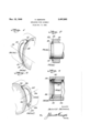
- FIG. 1 is a perspective view of one-half of an external retaining ring according to the invention, taken along a section line extending through its vertical axis or center line;
- Fig. 2 is a longitudinal section through a typical retaining ring assembly incorporating the retaining ring as shown in Fig. 1;
- Fig. 3 is a perspective view of one-half of an internal retaining ring according to the' invention.
- Fig. 4 is a longitudinal section through a typicai retaining ring assembly incorporating the retainingringasshowninFig.3.
- reference character Il designates a so-called external retaining ring, shown in half vertical section, of the type adapted to be sprung into an outwardly opening shaft groove provided to receive the same.
- the illustrated ring comprises an open-ended spring steel ring, the section height ofd which progressively decreases from its upper or middle section I I to the free ends thereof, which latter are provided with outwardly protruding lugs or ears i2 which are apertured as at il for the reception of the points of a handling tool. It will be understood that due to its taper, i. e. progressively decreasing section height, the ring as illustrated maintains its circularity under deforma.-l
- the ring In rather than being a fiat or plane ring as heretofore, is symmetrically bowed about a hypothetical line Il which extends transversely of the ring substantially intermediate its middle section ii and the free or open ends thereof.
- the ring is bowed to conform to the arc of a cylindrical surface Il of predetermined or fixed radius, the radius of said surface thus determining the contour of the ring as the latter is viewed in side edge elevation and the degree of bowing thereof.
- Fig. 2 which illustrates a typical retaining ring assembly employing a bowed external ring according to the invention
- the ring i when sprung into its shaft groovejl retains the property of fitting with a remarkably' high degree of pressure against the bottom of the groove throughout its full circumference.
- any axial restraint imposed thereon as it is fitted into its groove causes the ring to exert resilient pressure in axial direction between the fixed outer wall I1 of the groove and the adjacent end face I8 of the machine part I9 adapted to be secured by the ring. More specifically, with a ring disposed as in Fig.
- the bowed ring I0 abuts both along an edge portion 22 of its upper periphery and at opposite points 23, 23' of its lugs or ears I2 against the abutting end face i8 of the machine part, Whereas its horizontal middle sections 24 (24') abut against the outer fixed wall Il of the shaft groove.
- the effective width of the shaft groove Il is somewhat larger than that provided for conventional ilat rings, by an amount which equals the sum total of the maximum permissible tolerances ⁇ of the machine part, of the ring thickness and of the location of the groove in the shaft.
- the degree of bowing imparted to the the ringin its groove, the ring isrequired tobe' sprung into the groove in such manner that it exertsacertainaxialforceonthemaehinebal't. thus to act simultaneously as a circular spring and as a leaf spring.
- a ring according to the invention functions to resiliently hold the machine part against axial displacement and in such manner that no free end play thereof can' occur.
- the internal 'ring 2l tapers from its middle section 2i to inwardly extending ears 21, characterizing the internal ring, which latter are provided with apertures 2l to assist in ring handling.
- the ring 2l is symmetrically bowed about a hypothetical line 2l extending transversely of the ring substantially intermediate its middle section 2l and the open ends thereof, as by bending the same against a cylindrical surface 'Il of predetermined radius.
- the ring 2l is shown as sprung into its housing groove Il vthereby to secure the machine part I3 against axial displacement, the upper edge portion 24 of' the ring andthe opposed points 3B, It' of thering ears bear against the relatively outer wall It of the groove, whereas thev horizontal sections I1, I1' on the opposite face of the ring bear against the abutting end face 38 of the machine part Il, the latter being positioned to overhang the relatively inner wall llieof the groove.
- the internal ring 2l has pressure fit against the bottom of the groove and also acts as a leaf spring exerting endwise or axial pressure against the end face of the machine part to a. degree which resiliently secures the latter against free end play.
- is wider than grooves provided for conventional flat or plane rings by an amount which equals the sum total of the tolerances of the machine part ll, the thickness of the ring, and the location of the groove in the housing.
- the bowing of the ring at least equals the sum total of the .tolerances above enumerated so that when sprung into its groove -the ring exerts axial pressure against the machine part and secures the same against free end play as caused by vibrations, for example.
- a retaining ring assembly comprising the combination of a machine part, adapted to be located on and secured against axial end play relative to another part such as a shaft, housing and the like, said other part being provided with a retaining rlng groove, an open-ended spring retaining ring spring-seated in said groove and providing an artificial shoulder for locating the machine part, said groove having eiective width which is greater than the thickness of the ring by an amount which is at least as great as the total of the permissible tolerances of the machine part, of the thickness of the ring, and of the axial location of groove in said other part, said machine part having its one end face disposed to overhang the relatively inner wall of the groove, and the retaining ring being sprung into the groove between said overhanging end face of the machine part and the outer wall of the groove, the ring having diminishing section height from its upper middle section to its open ends and being symmetrically bowed about a line extending transversely of the ring substantially intermediate the middle section and the open ends thereof by a
Description
NV- 15 1949 H. HEIMANN 2,487,802
RETAINING RING ASSEMBLY l Filed Nov. a, 1944 www:
mensa Nov., 15, 1949 'UNITED STATES PATENT OFFICE RETAINING RING ASSEMBLY Heinrich Heimann, New York, N. Y., assignor to Waldes Koh-I-Noor, Inc., Long Island City, N. Y., a corporation of New York Application November 8, 1944, Serial No. 562,548 4 claims. (ci. :z5- 8.5)
This invention relates to improvements in retaining ring assemblies for securing machine parts, for example gearing, bearing races, pulleys and the like against axialdisplacement on shafts or in housings, and to an improved spring retaining ring for use therewith.
As usually constructed, spring retaining rings are of two main types. The rst -or so-called ordinary type retaining ring has uniform section height and equal thickness throughout and is characterized by an inner diameter, in the case of an external ring, and an outer diameter in the case of an internal ring, which equals the diameter of the bottom of the shaft or housing groove into which such rings are conventionally sprung, thus to insure that the ring seats against the groove bottom. However, due to the fact that such rings deform ovally when spread or compressed and are, moreover, operative only in their own plane, it is inherent in their construction that they have turning t against the groove bottom and hence do not exert any substantial pressure thereagainst or any axial or endwise pressure against the machine parts secured thereby. According to the second known type of spring retaining ring, the ring is tapered so that the section heights thereof decrease progressively from the ring mid section to the free ends thereof, the taper being calculated so that the ring maintains its circularity under deformation, i. e. when spread or compressed. Such rings can be dimensioned so that when sprung into their grooves they t tight against the bottom of the groove with a remarkably high pressure, and hence they have a pressure nt against the groove bottom as distinguished from the turning ilt characterizing the ordinary spring ring of uniform section height. However, the known tapered rings', like the so-called ordinary rings, are operative only in their own plane and hence are unable to exert any endwise force or thrust against the machine parts secured thereby.
Thus, both of the stated types of rings are objectionable for certain uses in that they are incapable of exactly locating a machine part relative, to shaft or housing due to the necessary tolerances in the length of the machine part itself, in the thickness of the retaining rings themselves and, last but not least, in the location of the groove in the shaft or housing. On the other hand, Iboth types of rings as heretofore constructed usually result in end play between the holding face of the ring and the corresponding abutting end face of the machine part to be held,
l 2 which can amount to the sum total of thetolerances enumerated above.
A principal object of this invention is the provision of a retaining ring assembly of simple and dependable construction employing a spring retaining ring of progressively decreasing section height for locating a machine part axially relative to a shaft or housing carrying the same while at the same time resiliently securing the part against end play.
Another object of the invention is the provision of a retaining ring assembly capable of resiliently securing a machine part against axial end play relative to a shaft or housing carrying the same, while at the same time permitting the necessary tolerances in the dimensioning of the machine part, the thickness of the ring itself, and in the location of the shaft or housing groove.
A further object of the invention is the provision of a. retaining ring assembly incorporating a retaining ring having pressure fit throughout its full circumference against the bottom of its groove and which is capable of exerting a substantial pressure in axial direction against the abutting end face of a machine part held by the seated ring.
A further object of the invention is the provision of a spring retaining ring characterized by diminishing section height from its mid section to the free ends thereof, which is also symmetrically bowed about a transverse line extending transversely of the ring substantially intermediate its middle section and the free or open ends thereof, and is thereby capable when properly positioned in its groove of exerting resilient pressure against an abutting machine part held thereby.
Other objects will be in part obvious and in part hereinafter pointed out in connection with the following analysis of this invention wherein are illustrated in detail several embodiments of the invention.
In the drawings- Fig. 1 is a perspective view of one-half of an external retaining ring according to the invention, taken along a section line extending through its vertical axis or center line;
Fig. 2 is a longitudinal section through a typical retaining ring assembly incorporating the retaining ring as shown in Fig. 1;
Fig. 3 is a perspective view of one-half of an internal retaining ring according to the' invention; and
Fig. 4 is a longitudinal section through a typicai retaining ring assembly incorporating the retainingringasshowninFig.3.
Referring to the drawings, reference character Il (Fig. l) designates a so-called external retaining ring, shown in half vertical section, of the type adapted to be sprung into an outwardly opening shaft groove provided to receive the same. The illustrated ring comprises an open-ended spring steel ring, the section height ofd which progressively decreases from its upper or middle section I I to the free ends thereof, which latter are provided with outwardly protruding lugs or ears i2 which are apertured as at il for the reception of the points of a handling tool. It will be understood that due to its taper, i. e. progressively decreasing section height, the ring as illustrated maintains its circularity under deforma.-l
tion.
According to the invention, the ring In, rather than being a fiat or plane ring as heretofore, is symmetrically bowed about a hypothetical line Il which extends transversely of the ring substantially intermediate its middle section ii and the free or open ends thereof. Preferably the ring is bowed to conform to the arc of a cylindrical surface Il of predetermined or fixed radius, the radius of said surface thus determining the contour of the ring as the latter is viewed in side edge elevation and the degree of bowing thereof.
As can be seen from Fig. 2, which illustrates a typical retaining ring assembly employing a bowed external ring according to the invention, the ring i when sprung into its shaft groovejl retains the property of fitting with a remarkably' high degree of pressure against the bottom of the groove throughout its full circumference. It will be moreover observed that due to thebowing of the ring any axial restraint imposed thereon as it is fitted into its groove causes the ring to exert resilient pressure in axial direction between the fixed outer wall I1 of the groove and the adjacent end face I8 of the machine part I9 adapted to be secured by the ring. More specifically, with a ring disposed as in Fig. 2, and with the machine part end face i8 overhanging the relatively inner wall 20 of the groove, the bowed ring I0 abuts both along an edge portion 22 of its upper periphery and at opposite points 23, 23' of its lugs or ears I2 against the abutting end face i8 of the machine part, Whereas its horizontal middle sections 24 (24') abut against the outer fixed wall Il of the shaft groove. Hence, with the ring being urged to plane form by reason of the restraint imposed on the opposite faces or sides thereof by the machine part and the fixed wall of the groove, the ring in tending to return to its bowed shape exerts endwise resilient pressure against the machine part thus to secure the part against end play.
According to a further feature of the invention, the effective width of the shaft groove Il is somewhat larger than that provided for conventional ilat rings, by an amount which equals the sum total of the maximum permissible tolerances` of the machine part, of the ring thickness and of the location of the groove in the shaft. At the I same time, the degree of bowing imparted to the the ringin its groove, the ring isrequired tobe' sprung into the groove in such manner that it exertsacertainaxialforceonthemaehinebal't. thus to act simultaneously as a circular spring and as a leaf spring. Hence a ring according to the invention functions to resiliently hold the machine part against axial displacement and in such manner that no free end play thereof can' occur.
According to the `embodiment illustrated in Figs. 3 and 4, illustrating, respectively, a so-called internal ring and an internal retaining ring assembly according to the invention, the internal 'ring 2l tapers from its middle section 2i to inwardly extending ears 21, characterizing the internal ring, which latter are provided with apertures 2l to assist in ring handling. As with the ring illustrated in Fig. 1, the ring 2l is symmetrically bowed about a hypothetical line 2l extending transversely of the ring substantially intermediate its middle section 2l and the open ends thereof, as by bending the same against a cylindrical surface 'Il of predetermined radius. In Fig. 4, wherein the ring 2l is shown as sprung into its housing groove Il vthereby to secure the machine part I3 against axial displacement, the upper edge portion 24 of' the ring andthe opposed points 3B, It' of thering ears bear against the relatively outer wall It of the groove, whereas thev horizontal sections I1, I1' on the opposite face of the ring bear against the abutting end face 38 of the machine part Il, the latter being positioned to overhang the relatively inner wall llieof the groove. As with the ring Il illustrated in Fig. 1, the internal ring 2l has pressure fit against the bottom of the groove and also acts as a leaf spring exerting endwise or axial pressure against the end face of the machine part to a. degree which resiliently secures the latter against free end play. As with the shaft groove, the housing groove 3| is wider than grooves provided for conventional flat or plane rings by an amount which equals the sum total of the tolerances of the machine part ll, the thickness of the ring, and the location of the groove in the housing. Moreover, the bowing of the ring at least equals the sum total of the .tolerances above enumerated so that when sprung into its groove -the ring exerts axial pressure against the machine part and secures the same against free end play as caused by vibrations, for example.
As many changes could be made in carrying out the above constructions without departing from the scope of the invention, it is intended that all matter contained in the above description or shown in the accompanying drawings shall be interpreted as illustrative and not in a limiting sense.
I claim:
l. -An open-ended retaining ring of the type adapted to be sprung into a circular groove provided in a shaft, housing bore or the like, and thereupon to form an artificial shoulder capable of securing a machine part againstaxial displacement comprising -an open-ended spring ring, the section heights of which 'progressively diminish from its upper middle section toits 'open ends whereby the ring maintains circularity under deformation and is thereby enabled to pressure-fit itself against the bottom of the groove into which it is sprung throughout its full arcuate length, the ring being symmetrically bowed about a line extending transversely of the ring substantially intermediate its middle section and its open ends by a calculated amount which is at least as great as the sum total of the maximum permissible tolerances of the machine part to be secured thereby, of the thickness of the ring and of the axial location of its groove in the shaft or housing.
2. A retaining ring assembly comprising the combination of a machine part, adapted to be located on and secured against axial end play relative to another part such as a shaft, housing and the like, said other part being provided with a retaining rlng groove, an open-ended spring retaining ring spring-seated in said groove and providing an artificial shoulder for locating the machine part, said groove having eiective width which is greater than the thickness of the ring by an amount which is at least as great as the total of the permissible tolerances of the machine part, of the thickness of the ring, and of the axial location of groove in said other part, said machine part having its one end face disposed to overhang the relatively inner wall of the groove, and the retaining ring being sprung into the groove between said overhanging end face of the machine part and the outer wall of the groove, the ring having diminishing section height from its upper middle section to its open ends and being symmetrically bowed about a line extending transversely of the ring substantially intermediate the middle section and the open ends thereof by a calculated amount which is at least as great as said total of the permissible tolerances whereby the ring pressure-seats itself against the groove 6 bottom throughout its full arcuate length and exerts resilient pressure in axial direction on the machine part.
3. A retaining ring assembly as set forth in claim 2, wherein said other part; consists of a shaft and the like, and said groove opens outwardly thereof.
4. A retaining ring assembly as set forth in claim 2, wherein said other part consists of a housing and the like, and said groove opens lnwardly to a housing bore.
HEINRICH HEIMANN.
REFERENCES CITED The following references are of record in the file of this patent:
UNITED STATES PATENTS Number Name Date 176,743 Garth et aln May 2, 1876 216,512 Dalzell June 1'?, 1879 454,289 Partz June 16, 1891 Re. 18,144 Heiermann Aug. 4, 1931 1,875,209 Baldwin Aug. 30, 1932 2,322,138 Jenny June 15, 1943 FOREIGN PATENTS Number Country Date 103,920 Australia May 6, 1938 463,684 Germany Aug. l, 1928 540,229 Germany Jan., 29, 193i 481,970 Great Britain Mar. 22, 1938
Priority Applications (5)
| Application Number | Priority Date | Filing Date | Title |
|---|---|---|---|
| US562548A US2487802A (en) | 1944-11-08 | 1944-11-08 | Retaining ring assembly |
| CH255527D CH255527A (en) | 1944-11-08 | 1946-09-30 | Device for securing a machine part against axial displacement with respect to a machine part that supports it. |
| GB34000/46A GB618842A (en) | 1944-11-08 | 1946-11-15 | Improvements in retaining rings |
| FR943654D FR943654A (en) | 1944-11-08 | 1946-11-16 | Improvements to locking ring assembly systems |
| DEW3546A DE852019C (en) | 1944-11-08 | 1950-09-10 | Device for securing a machine part against axial displacement with respect to a machine part that supports it |
Applications Claiming Priority (1)
| Application Number | Priority Date | Filing Date | Title |
|---|---|---|---|
| US562548A US2487802A (en) | 1944-11-08 | 1944-11-08 | Retaining ring assembly |
Publications (1)
| Publication Number | Publication Date |
|---|---|
| US2487802A true US2487802A (en) | 1949-11-15 |
Family
ID=24246722
Family Applications (1)
| Application Number | Title | Priority Date | Filing Date |
|---|---|---|---|
| US562548A Expired - Lifetime US2487802A (en) | 1944-11-08 | 1944-11-08 | Retaining ring assembly |
Country Status (5)
| Country | Link |
|---|---|
| US (1) | US2487802A (en) |
| CH (1) | CH255527A (en) |
| DE (1) | DE852019C (en) |
| FR (1) | FR943654A (en) |
| GB (1) | GB618842A (en) |
Cited By (14)
| Publication number | Priority date | Publication date | Assignee | Title |
|---|---|---|---|---|
| US3599769A (en) * | 1968-09-06 | 1971-08-17 | Grace W R & Co | Roller conveyor |
| US3696759A (en) * | 1970-03-09 | 1972-10-10 | Tridair Industries | Tie-down fitting |
| US3914071A (en) * | 1974-02-27 | 1975-10-21 | Imc Magnetics Corp | Electrically driven fan |
| US4692079A (en) * | 1984-09-14 | 1987-09-08 | Waldes Truarc Inc. | Bowed internal spring retaining ring that functions regardless of its orientation when installed in a groove |
| US4798548A (en) * | 1988-01-11 | 1989-01-17 | Outboard Marine Corporation | Propeller shaft bearing housing retention system |
| US4798075A (en) * | 1984-09-14 | 1989-01-17 | Waldes Truarc Inc. | Method and apparatus for making a bowed external spring retaining ring of the E-shaped type |
| US5201233A (en) * | 1992-01-29 | 1993-04-13 | General Motors Corporation | Retainer assembly with dished retaining ring |
| US5720530A (en) * | 1994-12-15 | 1998-02-24 | Skf Industrial Trading And Development Company B.V. | Hub unit with connection by means of cup spring |
| US6520724B1 (en) * | 1999-06-15 | 2003-02-18 | Robert Bosch Gmbh | Fastening element and method for axially securing and cushioning at least one component in an opening |
| US20060261662A1 (en) * | 2005-05-19 | 2006-11-23 | Sollami Jimmie L | Spring lock mechanism for a ground-engaging tool |
| US20060261663A1 (en) * | 2005-05-19 | 2006-11-23 | Sollami Jimmie L | Spring lock mechanism for a ground-engaging |
| US20110162469A1 (en) * | 2010-01-07 | 2011-07-07 | Hans-Juergen Oberle | Fastening a stop disk |
| CN104160176A (en) * | 2012-02-17 | 2014-11-19 | Ntn株式会社 | Electric linear actuator |
| US20150345602A1 (en) * | 2012-10-30 | 2015-12-03 | Ntn Corporation | Electric Linear Actuator |
Families Citing this family (2)
| Publication number | Priority date | Publication date | Assignee | Title |
|---|---|---|---|---|
| US3054173A (en) * | 1954-06-16 | 1962-09-18 | Frank A Rudman | Method of assembling pressure sealed joints in hollow vessels |
| GB752758A (en) * | 1954-08-17 | 1956-07-11 | Waldes Kohinoor Inc | Improvements in or relating to open ended spring retaining rings |
Citations (9)
| Publication number | Priority date | Publication date | Assignee | Title |
|---|---|---|---|---|
| US176743A (en) * | 1876-05-02 | Improvement in wagon-axles | ||
| US216512A (en) * | 1879-06-17 | Improvement in spring-washers for vehicle-axles | ||
| US454289A (en) * | 1891-06-16 | Washer | ||
| DE463684C (en) * | 1927-02-04 | 1928-08-01 | Vulkanwerk G M B H | Pin lock, especially for piston pins |
| USRE18144E (en) * | 1927-02-04 | 1931-08-04 | Wrist-pin construction | |
| DE540229C (en) * | 1927-02-04 | 1931-12-10 | Praez S Werkstaetten Seeger & | Pin lock, especially for piston pins |
| US1875209A (en) * | 1930-05-02 | 1932-08-30 | Albert J Weatherhead Jr | Securing means |
| GB481970A (en) * | 1936-09-28 | 1938-03-22 | Leslie Reid | Improvements in spring rings for preventing lateral displacement of machine parts |
| US2322138A (en) * | 1941-11-12 | 1943-06-15 | Wright Aeronautical Corp | Piston pin retainer |
Family Cites Families (1)
| Publication number | Priority date | Publication date | Assignee | Title |
|---|---|---|---|---|
| DE507430C (en) * | 1929-01-05 | 1930-09-16 | Anton Hanl | Roller bearings for wheel sets |
-
1944
- 1944-11-08 US US562548A patent/US2487802A/en not_active Expired - Lifetime
-
1946
- 1946-09-30 CH CH255527D patent/CH255527A/en unknown
- 1946-11-15 GB GB34000/46A patent/GB618842A/en not_active Expired
- 1946-11-16 FR FR943654D patent/FR943654A/en not_active Expired
-
1950
- 1950-09-10 DE DEW3546A patent/DE852019C/en not_active Expired
Patent Citations (9)
| Publication number | Priority date | Publication date | Assignee | Title |
|---|---|---|---|---|
| US176743A (en) * | 1876-05-02 | Improvement in wagon-axles | ||
| US216512A (en) * | 1879-06-17 | Improvement in spring-washers for vehicle-axles | ||
| US454289A (en) * | 1891-06-16 | Washer | ||
| DE463684C (en) * | 1927-02-04 | 1928-08-01 | Vulkanwerk G M B H | Pin lock, especially for piston pins |
| USRE18144E (en) * | 1927-02-04 | 1931-08-04 | Wrist-pin construction | |
| DE540229C (en) * | 1927-02-04 | 1931-12-10 | Praez S Werkstaetten Seeger & | Pin lock, especially for piston pins |
| US1875209A (en) * | 1930-05-02 | 1932-08-30 | Albert J Weatherhead Jr | Securing means |
| GB481970A (en) * | 1936-09-28 | 1938-03-22 | Leslie Reid | Improvements in spring rings for preventing lateral displacement of machine parts |
| US2322138A (en) * | 1941-11-12 | 1943-06-15 | Wright Aeronautical Corp | Piston pin retainer |
Cited By (18)
| Publication number | Priority date | Publication date | Assignee | Title |
|---|---|---|---|---|
| US3599769A (en) * | 1968-09-06 | 1971-08-17 | Grace W R & Co | Roller conveyor |
| US3696759A (en) * | 1970-03-09 | 1972-10-10 | Tridair Industries | Tie-down fitting |
| US3914071A (en) * | 1974-02-27 | 1975-10-21 | Imc Magnetics Corp | Electrically driven fan |
| US4692079A (en) * | 1984-09-14 | 1987-09-08 | Waldes Truarc Inc. | Bowed internal spring retaining ring that functions regardless of its orientation when installed in a groove |
| US4798075A (en) * | 1984-09-14 | 1989-01-17 | Waldes Truarc Inc. | Method and apparatus for making a bowed external spring retaining ring of the E-shaped type |
| US4798548A (en) * | 1988-01-11 | 1989-01-17 | Outboard Marine Corporation | Propeller shaft bearing housing retention system |
| US5201233A (en) * | 1992-01-29 | 1993-04-13 | General Motors Corporation | Retainer assembly with dished retaining ring |
| US5720530A (en) * | 1994-12-15 | 1998-02-24 | Skf Industrial Trading And Development Company B.V. | Hub unit with connection by means of cup spring |
| US6520724B1 (en) * | 1999-06-15 | 2003-02-18 | Robert Bosch Gmbh | Fastening element and method for axially securing and cushioning at least one component in an opening |
| US20060261662A1 (en) * | 2005-05-19 | 2006-11-23 | Sollami Jimmie L | Spring lock mechanism for a ground-engaging tool |
| US20060261663A1 (en) * | 2005-05-19 | 2006-11-23 | Sollami Jimmie L | Spring lock mechanism for a ground-engaging |
| US20110162469A1 (en) * | 2010-01-07 | 2011-07-07 | Hans-Juergen Oberle | Fastening a stop disk |
| CN104160176A (en) * | 2012-02-17 | 2014-11-19 | Ntn株式会社 | Electric linear actuator |
| US20140352466A1 (en) * | 2012-02-17 | 2014-12-04 | Ntn Corporation | Electric Linear Actuator |
| EP2816254A4 (en) * | 2012-02-17 | 2016-08-24 | Ntn Toyo Bearing Co Ltd | Electric linear actuator |
| US9574648B2 (en) * | 2012-02-17 | 2017-02-21 | Ntn Corporation | Electric linear actuator |
| US20150345602A1 (en) * | 2012-10-30 | 2015-12-03 | Ntn Corporation | Electric Linear Actuator |
| US9476489B2 (en) * | 2012-10-30 | 2016-10-25 | Ntn Corporation | Electric linear actuator |
Also Published As
| Publication number | Publication date |
|---|---|
| FR943654A (en) | 1949-03-15 |
| CH255527A (en) | 1948-06-30 |
| DE852019C (en) | 1952-10-09 |
| GB618842A (en) | 1949-02-28 |
Similar Documents
| Publication | Publication Date | Title |
|---|---|---|
| US2487802A (en) | Retaining ring assembly | |
| US3463520A (en) | Combination collar-clamp and shaft coupling | |
| US2382947A (en) | Securing means | |
| US4046028A (en) | Crank shaft | |
| US2141122A (en) | Cushioned roller bearing | |
| GB1531352A (en) | Shock absorber | |
| US2544631A (en) | Retaining ring assembly | |
| US2491310A (en) | Retaining ring | |
| US4195944A (en) | Frictional couplings | |
| US3145547A (en) | Alignment device | |
| US2713482A (en) | Washer assembly | |
| US2491306A (en) | Retaining ring | |
| US4728202A (en) | Shaft locking collar for bearing assemblies | |
| US3469494A (en) | Internal retaining ring | |
| JPS62171522A (en) | Bearing device with seal | |
| US3379072A (en) | Chain link and chain including said link | |
| US3063761A (en) | Bearing structure | |
| US4732495A (en) | Arrangement for adjustment of rolling bearing | |
| US4229117A (en) | Apparatus for securing a metal hoop onto a metal rim | |
| US2974501A (en) | Sealing rings | |
| US2018221A (en) | Bearing | |
| US3871192A (en) | Forked universal joint member | |
| US2665930A (en) | Eccentric ring locking means | |
| US3904005A (en) | Overrunning clutch | |
| US2080683A (en) | Pump construction |