WO2013115284A1 - Élément de support et outil de coupe - Google Patents
Élément de support et outil de coupe Download PDFInfo
- Publication number
- WO2013115284A1 WO2013115284A1 PCT/JP2013/052116 JP2013052116W WO2013115284A1 WO 2013115284 A1 WO2013115284 A1 WO 2013115284A1 JP 2013052116 W JP2013052116 W JP 2013052116W WO 2013115284 A1 WO2013115284 A1 WO 2013115284A1
- Authority
- WO
- WIPO (PCT)
- Prior art keywords
- holder
- insert
- mounting space
- slit
- insert mounting
- Prior art date
Links
Images


Classifications
-
- B—PERFORMING OPERATIONS; TRANSPORTING
- B23—MACHINE TOOLS; METAL-WORKING NOT OTHERWISE PROVIDED FOR
- B23B—TURNING; BORING
- B23B27/00—Tools for turning or boring machines; Tools of a similar kind in general; Accessories therefor
- B23B27/14—Cutting tools of which the bits or tips or cutting inserts are of special material
- B23B27/16—Cutting tools of which the bits or tips or cutting inserts are of special material with exchangeable cutting bits or cutting inserts, e.g. able to be clamped
- B23B27/1625—Cutting tools of which the bits or tips or cutting inserts are of special material with exchangeable cutting bits or cutting inserts, e.g. able to be clamped with plate-like cutting inserts of special shape clamped by a clamping member acting almost perpendicularly on the chip-forming plane
-
- B—PERFORMING OPERATIONS; TRANSPORTING
- B23—MACHINE TOOLS; METAL-WORKING NOT OTHERWISE PROVIDED FOR
- B23B—TURNING; BORING
- B23B27/00—Tools for turning or boring machines; Tools of a similar kind in general; Accessories therefor
- B23B27/04—Cutting-off tools
- B23B27/045—Cutting-off tools with chip-breaking arrangements
-
- B—PERFORMING OPERATIONS; TRANSPORTING
- B23—MACHINE TOOLS; METAL-WORKING NOT OTHERWISE PROVIDED FOR
- B23B—TURNING; BORING
- B23B27/00—Tools for turning or boring machines; Tools of a similar kind in general; Accessories therefor
- B23B27/04—Cutting-off tools
-
- B—PERFORMING OPERATIONS; TRANSPORTING
- B23—MACHINE TOOLS; METAL-WORKING NOT OTHERWISE PROVIDED FOR
- B23B—TURNING; BORING
- B23B27/00—Tools for turning or boring machines; Tools of a similar kind in general; Accessories therefor
- B23B27/14—Cutting tools of which the bits or tips or cutting inserts are of special material
- B23B27/16—Cutting tools of which the bits or tips or cutting inserts are of special material with exchangeable cutting bits or cutting inserts, e.g. able to be clamped
-
- B—PERFORMING OPERATIONS; TRANSPORTING
- B23—MACHINE TOOLS; METAL-WORKING NOT OTHERWISE PROVIDED FOR
- B23B—TURNING; BORING
- B23B29/00—Holders for non-rotary cutting tools; Boring bars or boring heads; Accessories for tool holders
- B23B29/04—Tool holders for a single cutting tool
- B23B29/043—Tool holders for a single cutting tool with cutting-off, grooving or profile cutting tools, i.e. blade- or disc-like main cutting parts
-
- B—PERFORMING OPERATIONS; TRANSPORTING
- B23—MACHINE TOOLS; METAL-WORKING NOT OTHERWISE PROVIDED FOR
- B23B—TURNING; BORING
- B23B29/00—Holders for non-rotary cutting tools; Boring bars or boring heads; Accessories for tool holders
- B23B29/04—Tool holders for a single cutting tool
- B23B29/06—Tool holders equipped with longitudinally-arranged grooves for setting the cutting tool
-
- B—PERFORMING OPERATIONS; TRANSPORTING
- B23—MACHINE TOOLS; METAL-WORKING NOT OTHERWISE PROVIDED FOR
- B23B—TURNING; BORING
- B23B2205/00—Fixation of cutting inserts in holders
- B23B2205/02—Fixation using an elastically deformable clamping member
-
- B—PERFORMING OPERATIONS; TRANSPORTING
- B23—MACHINE TOOLS; METAL-WORKING NOT OTHERWISE PROVIDED FOR
- B23B—TURNING; BORING
- B23B2205/00—Fixation of cutting inserts in holders
- B23B2205/12—Seats for cutting inserts
-
- Y—GENERAL TAGGING OF NEW TECHNOLOGICAL DEVELOPMENTS; GENERAL TAGGING OF CROSS-SECTIONAL TECHNOLOGIES SPANNING OVER SEVERAL SECTIONS OF THE IPC; TECHNICAL SUBJECTS COVERED BY FORMER USPC CROSS-REFERENCE ART COLLECTIONS [XRACs] AND DIGESTS
- Y10—TECHNICAL SUBJECTS COVERED BY FORMER USPC
- Y10T—TECHNICAL SUBJECTS COVERED BY FORMER US CLASSIFICATION
- Y10T407/00—Cutters, for shaping
- Y10T407/22—Cutters, for shaping including holder having seat for inserted tool
- Y10T407/2272—Cutters, for shaping including holder having seat for inserted tool with separate means to fasten tool to holder
- Y10T407/2282—Cutters, for shaping including holder having seat for inserted tool with separate means to fasten tool to holder including tool holding clamp and clamp actuator
- Y10T407/2286—Resiliently biased clamp jaw
- Y10T407/2288—Integral with holder
-
- Y—GENERAL TAGGING OF NEW TECHNOLOGICAL DEVELOPMENTS; GENERAL TAGGING OF CROSS-SECTIONAL TECHNOLOGIES SPANNING OVER SEVERAL SECTIONS OF THE IPC; TECHNICAL SUBJECTS COVERED BY FORMER USPC CROSS-REFERENCE ART COLLECTIONS [XRACs] AND DIGESTS
- Y10—TECHNICAL SUBJECTS COVERED BY FORMER USPC
- Y10T—TECHNICAL SUBJECTS COVERED BY FORMER US CLASSIFICATION
- Y10T407/00—Cutters, for shaping
- Y10T407/25—Cutters, for shaping including cut off tool
Definitions
- the present invention relates to a holder used for grooving and parting-off processing, and a cutting tool equipped with an insert for processing a workpiece.
- a slit is provided at the tip of the holder, and the insert is sandwiched between the upper and lower jaws located above and below the slit, and screwed.
- a restraint system is known in which the slit is tightened and the insert is pressed and fixed.
- V-shaped and wavy concave grooves are provided on the upper and lower surfaces of the insert, and V-shaped and wavy convex portions that are fitted into the concave grooves are provided on the upper and lower jaws of the holder.
- a method of fitting and fixing a convex portion in a concave groove is disclosed. This increases the binding force.
- the screw is provided at the central portion of the upper jaw to which the screw is screwed. Since the upper jaw is bent and tightened, when screwed, the upper jaw is bent at the center portion where the screw is screwed. Become a shape. However, since the insert is mounted at either end with respect to the width direction of the holder, when tightened with a screw, the upper jaw presses the insert downward and the outer side of the holder with respect to the width direction of the holder. The direction is also powerful. For this reason, there is a possibility that the insert may be attached while being inclined outward with respect to the width direction of the holder, or the insert may be detached outward.
- Patent Document 2 in order to prevent the insert from falling to the outside, the end length of the slit is changed so that the insert mounting side is longer than the other end.
- a holder that is slanted so that the other end side is the front is disclosed.
- the holder of the present invention is a holder provided with a substantially rod-shaped shank part and a head part integrally formed with the shank part located on one end side of the shank part,
- the head portion includes an insert mounting space on one side of a tip, an upper jaw and a lower jaw sandwiching the insert mounting space from above and below, a slit extending rearward from the insert mounting space, an upper jaw connecting portion divided by the slit, and A lower jaw connecting portion, an upper clamp surface facing the insert mounting space of the upper jaw, and a lower clamp surface facing the insert mounting space of the lower jaw,
- a groove is coupled to the back of the slit, and the groove is disposed such that the thickness from the upper surface of the holder is thinner than the thickness from the upper surface of the holder to the slit, and the insert mounting space side
- the length extends from the side surface toward the opposite side surface and does not penetrate through the side surface opposite to the side surface on the insert mounting space side.
- a groove for reducing the thickness from the upper surface of the holder is connected to the back of the slit, and this groove is formed from the side surface on the insert mounting space side to the middle, and the insert mounting space side It does not penetrate the side opposite to the side.
- the upper jaw can be deformed to such an extent that the insert can be prevented from falling outward.
- the insert can be firmly restrained by preventing the insert from falling outward.
- channel does not penetrate the side surface on the opposite side to the insert attachment space side, the rigidity with respect to the chatter of a holder improves. As a result, it is possible to effectively suppress the occurrence of chatter when the insert is mounted for cutting.
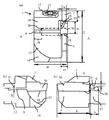
- worn with the insert in the suitable embodiment of this invention is shown, (a) is a perspective view, (b) is a top view.
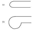
- 1 shows the shape of a portion R where a groove behind the slit is not formed, (a) the curved surface has the same configuration as the lower surface of the upper jaw, and (b) the curved surface exists below the lower surface of the upper jaw. It is a schematic diagram which shows a structure.
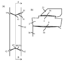
- FIG. 5 is an enlarged cross-sectional view for explaining a shape of (a) one example and (b) another example of both side end portions of the protruding portion of the cutting insert of FIG. 4. It is an expanded sectional view for demonstrating the shape of (a) an example of the both-ends part of the protrusion part of the conventional cutting insert, (b) another example, (c) another example.
- FIG. 1-2 shows a preferred embodiment of the present invention, and a cutting tool according to a preferred embodiment of the present invention will be described with reference to FIGS. 1 and 2.
- FIG. 1 shows a preferred embodiment of the present invention, and a cutting tool according to a preferred embodiment of the present invention will be described with reference to FIGS. 1 and 2.
- FIG. 1 shows a preferred embodiment of the present invention, and a cutting tool according to a preferred embodiment of the present invention will be described with reference to FIGS. 1 and 2.
- a throw-away cutting tool (hereinafter abbreviated as a cutting tool) 1 in which an insert 30 is mounted on the holder 2 of the present embodiment is particularly suitable for grooving and parting off.
- the cutting tool 1 includes a substantially rod-shaped shank portion 3 and a head portion 4 that is located on one end side of the shank portion 3 and formed integrally with the shank portion 3.
- the head portion 4 includes an insert mounting space 5 on one side A of the tip, an upper jaw 7 and a lower jaw 8 that sandwich the insert mounting space 5 from above and below, and a slit 9 that is connected to the rear from the insert mounting space 5.
- the head portion 4 includes an upper jaw connecting portion 11 and a lower jaw connecting portion 12 which are divided by the slit 9.
- An upper jaw fixing portion 10 is provided on the other side B side of the upper jaw 7.
- An upper jaw fixing portion 14 is provided on the other side B side of the lower jaw 8. The upper jaw 7 and the upper jaw fixing part 10 and the upper jaw connecting part 11 are connected, and the lower jaw 8 and the lower jaw fixing part 14 and the lower jaw connecting part 12 are connected.
- the upper jaw fixing part 10 has a through hole 15 for inserting the screw 13, and the lower jaw connecting part 12 has a screw hole (not shown) into which the screw 13 is screwed.
- An upper clamp surface 18 exists on the lower surface of the upper jaw 7, and a lower clamp surface 19 exists on the upper surface of the lower jaw 8. Then, by inserting the screw 13 from the through hole 15 of the upper jaw fixing portion 10 and screwing it into the screw hole of the lower jaw connecting portion 12, the upper clamp surface 18 of the upper jaw 7 and the lower clamp surface 19 of the lower jaw 8 are inserted into the insert mounting space.
- the insert 30 to be attached to 5 is tightened.
- the insert 30 is mounted such that the cutting edge portion 31 is located from the tip end side to the outside of the insert mounting space 5.
- a columnar groove 20 existing in the direction perpendicular to the longitudinal direction of the holder 2, that is, the width direction of the shank 3 is connected to the back of the slit 9.
- the cylindrical groove 20 is provided so that the thickness of the upper jaw connecting portion 11 is reduced, and extends from the side surface A on the insert mounting space 5 side in a direction perpendicular to the longitudinal direction of the holder 2 and on the opposite side surface. It consists of a length up to the middle of the slit 9 without penetrating B.
- the screw 13 is screwed into a position on the other side B side of the upper jaw 7, but is screwed into a position on the A side, that is, a position adjacent to the upper jaw 7 as much as possible in order to increase the restraining force of the insert 30.
- the end of the cylindrical groove 20 is provided on the other side B side than the center position of the through hole 15 provided in the upper jaw connecting portion 11.
- the center of the through hole 15 is located at a position 45 to 80% of the length of the cylindrical groove 20, that is, a position 45 to 80% of the length of the cylindrical groove 20 from the side surface A of the cylindrical groove 20. Provided. Thereby, the insert 30 can be firmly restrained.
- the screw hole of the lower jaw connecting portion 12 is slightly shifted to the other side B side with respect to the through hole 15. Accordingly, when the screw 13 is screwed, it is possible to increase the force of decentering the screw 13 and pressing the upper jaw 7 toward the B side opposite to the A side.
- the length of the cylindrical groove 20 is 50 to 75% of the width of the holder 2 when the holder 2 is viewed from the front end, the fall of the insert 30 to the outside can be efficiently suppressed.
- the rigidity of the holder 2 can be improved and the occurrence of chatter in the insert being processed can be effectively suppressed.
- a groove having another shape such as an elliptical columnar groove, a polygonal columnar groove, a conical groove, or a polygonal pyramidal groove may be used.
- the holder 2 extends in a direction perpendicular to the longitudinal direction from the front end to the rear end of the holder 2 in plan view.
- the cylindrical groove 20 extends in a direction perpendicular to the longitudinal direction of the holder 2 from one side A on the insert mounting space 5 side to the other side B on the opposite side.
- channel 20 is not limited to this, You may arrange
- the columnar groove 20 is disposed obliquely, it is desirable that the columnar groove 20 is disposed so as to be inclined toward the distal end side from one side A toward the other side B.
- the shape of the back of the slit 9 is curved when viewed from the side B opposite to the side A where the insert mounting space 5 of the holder 2 is provided, and the holder in the back of the slit 9 is curved. 2 is not thinner than the thickness from the other part of the slit 9 to the upper surface of the holder 2.
- the portion R where the cylindrical groove 20 in the back of the slit 9 is not formed is a curved surface in which the thickness of the upper jaw 7 is not thinned, as shown in FIGS. Without placing a curved surface above the height, the curved surface is the same as the lower surface of the upper jaw 7 as shown in FIG.
- the thickness of the thinnest portion of the thickness from the upper surface of the holder 2 to the cylindrical groove 20, that is, the thinnest portion of the upper jaw connecting portion 11 is used.
- the thickness t of a certain thinnest part is 1 to 3 mm, the upper jaw 7 can be flexed appropriately by optimizing the rigidity of the upper jaw connecting part 11. As a result, the occurrence of chatter during cutting can be suppressed, and the insert 30 can be firmly restrained by bending the upper jaw 7 by tightening the screw 13 by human force.
- the upper clamp surface 18 that comes into contact with the insert 30 of the upper jaw 7 and the lower clamp surface 19 that comes into contact with the insert 30 of the lower jaw 8 are recessed or projected in parallel from the tip toward the rear (see FIG. 2 has a protruding portion protruding toward the insert mounting space 5 side.
- the insert 30 has a convex portion or a concave groove (a concave groove fitted in the convex portion of the lower clamp surface 19 in FIG. The displacement can be suppressed and the binding force of the insert 30 can be increased.
- a notched lower jaw adjacent portion 17 is provided in the lower jaw fixing portion 14 located on the side of the insert 30 of the lower jaw 7 in order to provide a relief to avoid contact with the work material. It has been.
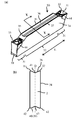
- FIG. 4 shows an example of the insert 30 attached to the holder of FIG. 1-2.
- the insert 30 includes a substantially prismatic rod-shaped insert main body 32 and a cutting edge portion 31 provided at an end portion in the longitudinal direction L of the insert main body 32. Cutting edge portions 31 are respectively provided at both ends of the.
- the insert 30 is a so-called dogbone-shaped insert having a substantially prismatic rod shape as a whole, the insert body 32 has a constant width in the longitudinal direction, and the side surface 34 is a surface perpendicular to the width direction of the insert 30. It has become.
- the cutting blade portion 31 has a substantially trapezoidal shape with the upper side wider than the lower side when viewed from the front end. That is, the side surface 44 of the cutting blade portion 31 is inclined, and the cutting blade 33 of the cutting blade portion 31 is provided with a positive clearance angle.
- the insert 30 has a line-symmetric shape with respect to the center line O in the width direction.
- the insert main body 32 includes a protruding portion 35 that protrudes upward from the cutting edge portion 31, and the protruding portion 35 has a longitudinal shape whose center is recessed in a V shape in a cross-sectional view perpendicular to the longitudinal direction. It has an upper clamping surface 36 extending in the direction.
- the center part was dented in the V shape at the seating surface 39 located in the opposite side with respect to the upper clamp surface 36 of the insert main body 32, ie, lower
- the central bottom surface 43 has a lower clamp surface 40 that is retracted upward. Then, the upper clamp surface 36 of the insert 30 and the upper clamp surface 18 of the holder 2 are fitted together, and the lower clamp surface 40 of the insert 30 is fitted and fixed to the lower clamp surface 19 of the holder 2.
- At least one of the upper clamp surface 36 and the lower clamp surface 40 of the insert 30 has a central portion protruding toward the insert mounting space 5 in the side view of the holder 2. It consists of a curved surface that is curved.
- both side ends of the protrusion 35 positioned outside the both ends in the direction perpendicular to the longitudinal direction L of the upper clamp surface 36.
- Each of the portions (hereinafter referred to as both side end portions) 37 has a concave shape in a sectional view perpendicular to the longitudinal direction L.
- both end portions 37 of the upper clamp surface 50 when both end portions 37 of the upper clamp surface 50 have a flat C surface shape, it corresponds to both end portions of the mold for molding the insert 30.
- the shape to be sharpened has a sharp pointed tip, and this sharp part is easily chipped.
- both side end portions 37 of the projecting portion since both side end portions 37 of the projecting portion have a concave shape, the shape of the end portion of the mold is also a shape that is not so sharp, and it is possible to suppress mold defects. .
- the shape of the side end portions 37 is less likely to chip even when chips are hit during cutting, as compared with FIGS. 7 (a) and 7 (b).
- the flat portion 38 exists between the upper clamp surface 36 and the side end portions 37, but the flat portion 38 may not be provided.
- the width of the side end portions 37 that are recessed in a concave shape is 0.05 to 0.2 mm.
- the direction in which the insert 30 is sandwiched between the holders 2 is defined as the vertical direction, and among the vertical directions, the side where the cutting blade is provided in the cutting blade portion 31 is defined as the upper side. is doing.
- the shape of the side end portions 37 may be a shape in which the C surface and the flat surface are combined from the center side as shown in FIG.
- the shape of the side end portions 37 is more preferably a concave curved surface.
- both side end portions 37 are recessed in the shape of a concave curved surface, it is more difficult to chip when chips are hit.
- the cutting oil flows to the cutting edge portion 31 without causing turbulent flow, the supply of the cutting oil is smooth.
- the radius of curvature of the concave curved surface is 0.05 to 0.4 mm.
- both side end portions 42 on the seating surface 39 side that are located outside both ends in the direction perpendicular to the longitudinal direction L of the lower clamp surface 40 are longitudinal.
- it has a concave shape like the side end portions 37.
- the center position of the through hole (ratio to the total length of the through hole from the side surface on the insert mounting space side of the cylindrical groove): described in Table 1 as the through hole position.
- the portion where the cylindrical groove at the back of the slit was not formed was arcuate.
- Slit thickness X 1mm ⁇ Insert>
- Insert shape Kyocera insert GMM2020R-MT-15D Width wi: 2mm Height hi in the center in the width direction: 4.3 mm (shape in which the center of the upper and lower surfaces is recessed in a V shape in a cross-sectional view)
- Length li 20 mm (Sample No.
- the cutting tool was cut under the following conditions to evaluate the occurrence of chatter and cutting performance during cutting.
- Work material SK material Machining form: Horizontal feed
- Variable feed 0.3 mm / rev Environment: Evaluation of use of water-soluble cutting oil: Cutting was carried out to a cutting length of 10 mm by changing the cutting depth, and the cutting depth at which the insert was detached from the holder was evaluated.
- the upper jaw connecting portion is arranged so as to be thin, extends from the side surface on the insert mounting space side in a direction perpendicular to the longitudinal direction of the holder, and does not penetrate the opposite side surface.
- Sample No. having a cylindrical groove having a length up to the middle of the back. In I-3 to 8 and 12, the binding force of the insert to the holder was strong, and the occurrence of chatter could be suppressed.
- Inserts having the following dimensions in which both end portions of the protruding portion have the shape shown in Table 2 were prepared, and the life of the mold and the presence or absence of burrs after firing were evaluated when the molded body was produced.
- variety of the both-ends part was 0.1 mm.
- Sample No. The radius of curvature in II-1 is 0.1 mm.
- Insert shape Kyocera insert GDM2020N-010PQ Width wi: 2mm Height hi at the center in the width direction: 4.3 mm (length between upper center bottom surface and lower center bottom surface)
- Length li 20mm ⁇ Holder> Width W when viewed from the tip: 12 mm Height H when viewed from the tip: 18.5 mm
- Upper jaw height h 4 mm
- Upper and lower jaw width w 1.7 mm
- Distance from rear end of maxilla to cylindrical groove L 6mm Cylindrical groove (diameter of cylindrical groove: 3 mm, ratio of length of cylindrical groove to width perpendicular to holder longitudinal direction: 65%, thinnest thickness of upper jaw (above upper cylindrical groove) Thickness) t: 1.5mm)
- Slit thickness X 1mm ⁇ Cutting conditions>
- Work material S45C Processing form: Cut-off processing feed: 0.05mm / rev Environment: Uses oil-based cutting oil
- both ends of the projecting portion are extended from the upper clamp surface of FIG. II-3 and Sample No. 2 consisting of a horizontal plane parallel to the width direction of the insert of FIG. In II-4, burrs occurred at both end portions of the protruding portion during molding of the insert, resulting in a dimensional defect.
- sample No. 2 in which both end portions 7 in FIG. In II-5, the mold to be molded was easily chipped.
- Cutting tool (slow-away cutting tool) 2 Holder (holder for grooving) 3 Shank part 4 Head part 5 Insert mounting space 7 Upper jaw 8 Lower jaw 9 Slit 10 Upper jaw fixing part 11 Upper jaw connection part 12 Lower jaw connection part 13 Screw 14 Lower jaw fixing part 15 Through hole 17 Lower jaw adjacent part 18 Upper clamp surface 19 Lower clamp surface 20 Cylindrical groove 30 insert
Landscapes
- Engineering & Computer Science (AREA)
- Mechanical Engineering (AREA)
- Cutting Tools, Boring Holders, And Turrets (AREA)
- Knives (AREA)
Abstract
Priority Applications (5)
| Application Number | Priority Date | Filing Date | Title |
|---|---|---|---|
| EP13743692.9A EP2810726B1 (fr) | 2012-01-30 | 2013-01-30 | Élément de support et outil de coupe |
| CN201380007319.0A CN104080563B (zh) | 2012-01-30 | 2013-01-30 | 刀架以及切削工具 |
| JP2013556480A JP5717885B2 (ja) | 2012-01-30 | 2013-01-30 | ホルダおよび切削工具 |
| US14/373,639 US9555477B2 (en) | 2012-01-30 | 2013-01-30 | Holder and cutting tool |
| KR1020147020022A KR101700706B1 (ko) | 2012-01-30 | 2013-01-30 | 홀더 및 절삭공구 |
Applications Claiming Priority (4)
| Application Number | Priority Date | Filing Date | Title |
|---|---|---|---|
| JP2012-016750 | 2012-01-30 | ||
| JP2012016750 | 2012-01-30 | ||
| JP2012-261182 | 2012-11-29 | ||
| JP2012261182 | 2012-11-29 |
Publications (1)
| Publication Number | Publication Date |
|---|---|
| WO2013115284A1 true WO2013115284A1 (fr) | 2013-08-08 |
Family
ID=48905316
Family Applications (1)
| Application Number | Title | Priority Date | Filing Date |
|---|---|---|---|
| PCT/JP2013/052116 WO2013115284A1 (fr) | 2012-01-30 | 2013-01-30 | Élément de support et outil de coupe |
Country Status (6)
| Country | Link |
|---|---|
| US (1) | US9555477B2 (fr) |
| EP (1) | EP2810726B1 (fr) |
| JP (1) | JP5717885B2 (fr) |
| KR (1) | KR101700706B1 (fr) |
| CN (1) | CN104080563B (fr) |
| WO (1) | WO2013115284A1 (fr) |
Families Citing this family (5)
| Publication number | Priority date | Publication date | Assignee | Title |
|---|---|---|---|---|
| WO2016068120A1 (fr) * | 2014-10-29 | 2016-05-06 | 京セラ株式会社 | Support, outil de coupe, et procédé de production d'un objet coupé |
| CN105750610B (zh) * | 2016-05-11 | 2018-06-08 | 朴虎林 | 一种龙门式刨槽机 |
| CN105750611B (zh) * | 2016-05-11 | 2018-06-08 | 朴虎林 | 一种刨槽机的刀架 |
| DE102016109327A1 (de) | 2016-05-20 | 2017-11-23 | Hartmetall-Werkzeugfabrik Paul Horn Gmbh | Halter für ein Werkzeug zur spanenden Bearbeitung, insbesondere für ein Langdrehwerkzeug |
| EP3785830A1 (fr) * | 2019-08-30 | 2021-03-03 | Walter Ag | Insert de découpe pour séparer une pièce métallique |
Citations (6)
| Publication number | Priority date | Publication date | Assignee | Title |
|---|---|---|---|---|
| JP2001515794A (ja) | 1997-09-10 | 2001-09-25 | セコ ツールズ アクティエボラーグ(プブル) | 切り屑を除去する機械加工用の工具 |
| JP2003245805A (ja) * | 2002-02-25 | 2003-09-02 | Kyocera Corp | 溝入れ用切削インサート |
| JP2006263846A (ja) | 2005-03-23 | 2006-10-05 | Kyocera Corp | 溝入れ加工用ホルダおよび切削工具 |
| JP2007069291A (ja) * | 2005-09-06 | 2007-03-22 | Mitsubishi Materials Corp | 切削インサート及びインサート着脱式切削工具 |
| JP2010513033A (ja) * | 2006-12-18 | 2010-04-30 | ケンナメタル インコーポレイテッド | 特にバリ取り工具用の工具ホルダ、および工具ホルダ用切削体 |
| JP2011005626A (ja) * | 2009-05-27 | 2011-01-13 | Kyocera Corp | 切削工具 |
Family Cites Families (16)
| Publication number | Priority date | Publication date | Assignee | Title |
|---|---|---|---|---|
| US3844008A (en) * | 1973-03-14 | 1974-10-29 | Valeron Corp | Cutting tool |
| SE452713B (sv) * | 1986-04-07 | 1987-12-14 | Sandvik Ab | Verktyg for avstickning samt sker for anvendning i nemnda verktyg |
| SE502242C2 (sv) * | 1991-07-31 | 1995-09-25 | Sandvik Ab | Avstickningsverktyg med infästningsdelar orienterade i två mot varandra vinkelräta plan |
| SE509339C2 (sv) * | 1994-12-08 | 1999-01-11 | Seco Tools Ab | Verktyg och skär för spånavskiljande bearbetning |
| DE69802998T2 (de) * | 1997-03-27 | 2002-07-18 | Sandvik Ab | Ein- und Abstechwerkzeug |
| US5921724A (en) * | 1997-12-18 | 1999-07-13 | Kennametal Inc. | Insert and toolholder for machining operations |
| US6334742B1 (en) * | 2000-02-28 | 2002-01-01 | Sandvik Inc. | Parting/grooving insert secured by friction in a holder |
| JP2002273608A (ja) * | 2001-03-19 | 2002-09-25 | Mitsubishi Materials Corp | 内径加工用工具 |
| JP4407503B2 (ja) * | 2004-12-16 | 2010-02-03 | 三菱マテリアル株式会社 | 切削インサートのクランプ機構 |
| JP2007144573A (ja) * | 2005-11-29 | 2007-06-14 | Kyocera Corp | 端面溝入れ加工用ホルダおよびそれを用いた切削工具 |
| JP5028883B2 (ja) * | 2006-06-30 | 2012-09-19 | 三菱マテリアル株式会社 | インサート着脱式切削工具 |
| JP2008238316A (ja) * | 2007-03-27 | 2008-10-09 | Kyocera Corp | 切削工具 |
| CN101795800B (zh) * | 2007-08-30 | 2012-03-21 | 京瓷株式会社 | 切削工具以及切削方法 |
| JP5040591B2 (ja) | 2007-10-30 | 2012-10-03 | 三菱マテリアル株式会社 | インサート着脱式切削工具のヘッド部材およびインサート着脱式切削工具 |
| DE102008063127A1 (de) * | 2008-12-24 | 2010-07-01 | Gühring Ohg | Werkzeug mit einem lösbar gespannten Schneidkörper |
| US9242302B2 (en) * | 2009-12-14 | 2016-01-26 | Kyocera Corporation | Cutting tool holder, cutting tool, and method of manufacturing machined product using the same |
-
2013
- 2013-01-30 CN CN201380007319.0A patent/CN104080563B/zh active Active
- 2013-01-30 EP EP13743692.9A patent/EP2810726B1/fr active Active
- 2013-01-30 WO PCT/JP2013/052116 patent/WO2013115284A1/fr active Application Filing
- 2013-01-30 US US14/373,639 patent/US9555477B2/en active Active
- 2013-01-30 JP JP2013556480A patent/JP5717885B2/ja active Active
- 2013-01-30 KR KR1020147020022A patent/KR101700706B1/ko active IP Right Grant
Patent Citations (6)
| Publication number | Priority date | Publication date | Assignee | Title |
|---|---|---|---|---|
| JP2001515794A (ja) | 1997-09-10 | 2001-09-25 | セコ ツールズ アクティエボラーグ(プブル) | 切り屑を除去する機械加工用の工具 |
| JP2003245805A (ja) * | 2002-02-25 | 2003-09-02 | Kyocera Corp | 溝入れ用切削インサート |
| JP2006263846A (ja) | 2005-03-23 | 2006-10-05 | Kyocera Corp | 溝入れ加工用ホルダおよび切削工具 |
| JP2007069291A (ja) * | 2005-09-06 | 2007-03-22 | Mitsubishi Materials Corp | 切削インサート及びインサート着脱式切削工具 |
| JP2010513033A (ja) * | 2006-12-18 | 2010-04-30 | ケンナメタル インコーポレイテッド | 特にバリ取り工具用の工具ホルダ、および工具ホルダ用切削体 |
| JP2011005626A (ja) * | 2009-05-27 | 2011-01-13 | Kyocera Corp | 切削工具 |
Non-Patent Citations (1)
| Title |
|---|
| See also references of EP2810726A4 |
Also Published As
| Publication number | Publication date |
|---|---|
| EP2810726A4 (fr) | 2015-09-16 |
| KR20140114835A (ko) | 2014-09-29 |
| CN104080563B (zh) | 2016-04-13 |
| US20150030400A1 (en) | 2015-01-29 |
| JP5717885B2 (ja) | 2015-05-13 |
| EP2810726B1 (fr) | 2019-02-27 |
| EP2810726A1 (fr) | 2014-12-10 |
| KR101700706B1 (ko) | 2017-01-31 |
| US9555477B2 (en) | 2017-01-31 |
| JPWO2013115284A1 (ja) | 2015-05-11 |
| CN104080563A (zh) | 2014-10-01 |
Similar Documents
| Publication | Publication Date | Title |
|---|---|---|
| JP5717885B2 (ja) | ホルダおよび切削工具 | |
| US7785045B2 (en) | Insert with a mounting hole and toolholder including a cutting insert | |
| JP5115148B2 (ja) | インサート着脱式切削工具のヘッド部材およびインサート着脱式切削工具 | |
| CN108602130B (zh) | 用于金属切削的面切槽刀具主体 | |
| JP5239471B2 (ja) | プランジ加工用カッタおよびプランジ加工方法 | |
| US6843620B2 (en) | Cutting tool and indexiable insert therefor | |
| JP5157660B2 (ja) | 切削インサートおよびインサート着脱式切削工具 | |
| JP5701321B2 (ja) | 切削工具 | |
| JP5267173B2 (ja) | インサート着脱式切削工具 | |
| WO2017135291A1 (fr) | Support pour élément tranchant à pointe d'aube remplaçable | |
| JP6210276B2 (ja) | スローアウェイ式切削工具 | |
| JP2009119572A (ja) | インサート及び刃先交換式切削工具 | |
| CN114713867B (zh) | 刀片座 | |
| CZ301931B6 (cs) | Protahovací nástroj a protahovací desticka | |
| JP2008213077A (ja) | 切削インサート及びインサート着脱式切削工具 | |
| JP4962157B2 (ja) | 押え金、工具ホルダ、およびスローアウェイ式切削工具 | |
| JP5289034B2 (ja) | ホルダおよび切削工具並びにそれを用いた切削方法 | |
| JP2007061990A (ja) | スローアウェイ式工具 | |
| JP5780930B2 (ja) | スローアウェイ式切削工具 | |
| JP2016007684A (ja) | 切削工具 | |
| JP4395397B2 (ja) | スローアウェイチップおよびそれを用いた切削工具 | |
| JP4548132B2 (ja) | 切削インサートのクランプ機構 | |
| JP2008238315A (ja) | 切削工具 | |
| JP2005279823A5 (fr) | ||
| JP2017121668A (ja) | 切削工具の板状部材、ツールブロック、および切削工具 |
Legal Events
| Date | Code | Title | Description |
|---|---|---|---|
| 121 | Ep: the epo has been informed by wipo that ep was designated in this application |
Ref document number: 13743692 Country of ref document: EP Kind code of ref document: A1 |
|
| ENP | Entry into the national phase |
Ref document number: 2013556480 Country of ref document: JP Kind code of ref document: A |
|
| WWE | Wipo information: entry into national phase |
Ref document number: 2013743692 Country of ref document: EP |
|
| ENP | Entry into the national phase |
Ref document number: 20147020022 Country of ref document: KR Kind code of ref document: A |
|
| WWE | Wipo information: entry into national phase |
Ref document number: 14373639 Country of ref document: US |
|
| NENP | Non-entry into the national phase |
Ref country code: DE |