WO2013114575A1 - 車両制御装置および鉄道用ハイブリッド車両の制御方法 - Google Patents
車両制御装置および鉄道用ハイブリッド車両の制御方法 Download PDFInfo
- Publication number
- WO2013114575A1 WO2013114575A1 PCT/JP2012/052181 JP2012052181W WO2013114575A1 WO 2013114575 A1 WO2013114575 A1 WO 2013114575A1 JP 2012052181 W JP2012052181 W JP 2012052181W WO 2013114575 A1 WO2013114575 A1 WO 2013114575A1
- Authority
- WO
- WIPO (PCT)
- Prior art keywords
- engine
- generator
- controller
- converter
- rotational speed
- Prior art date
Links
- 238000000034 method Methods 0.000 title claims description 51
- 239000000446 fuel Substances 0.000 claims abstract description 20
- 238000002347 injection Methods 0.000 claims abstract description 20
- 239000007924 injection Substances 0.000 claims abstract description 20
- 230000001172 regenerating effect Effects 0.000 claims description 24
- 238000012423 maintenance Methods 0.000 claims description 15
- 230000004913 activation Effects 0.000 description 19
- 238000010586 diagram Methods 0.000 description 18
- 230000006870 function Effects 0.000 description 4
- SNUZIZXJHSORAI-UHFFFAOYSA-N CNC(=O)c1ccc2-c3cc(nn3CCOc2c1)-c1ncnn1-c1ccc(F)cc1F Chemical compound CNC(=O)c1ccc2-c3cc(nn3CCOc2c1)-c1ncnn1-c1ccc(F)cc1F SNUZIZXJHSORAI-UHFFFAOYSA-N 0.000 description 3
- 230000002159 abnormal effect Effects 0.000 description 3
- 230000007704 transition Effects 0.000 description 3
- 230000009471 action Effects 0.000 description 2
- 238000006243 chemical reaction Methods 0.000 description 2
- 238000002485 combustion reaction Methods 0.000 description 2
- 238000001514 detection method Methods 0.000 description 2
- 230000000694 effects Effects 0.000 description 2
- 230000007613 environmental effect Effects 0.000 description 2
- 230000012447 hatching Effects 0.000 description 2
- 230000007257 malfunction Effects 0.000 description 2
- 230000008569 process Effects 0.000 description 2
- 230000008929 regeneration Effects 0.000 description 2
- 238000011069 regeneration method Methods 0.000 description 2
- HBBGRARXTFLTSG-UHFFFAOYSA-N Lithium ion Chemical compound [Li+] HBBGRARXTFLTSG-UHFFFAOYSA-N 0.000 description 1
- 230000007423 decrease Effects 0.000 description 1
- 238000007599 discharging Methods 0.000 description 1
- 238000005516 engineering process Methods 0.000 description 1
- 229910001416 lithium ion Inorganic materials 0.000 description 1
- 238000005461 lubrication Methods 0.000 description 1
- 230000009467 reduction Effects 0.000 description 1
- 230000004044 response Effects 0.000 description 1
- 230000004043 responsiveness Effects 0.000 description 1
Images


Classifications
-
- B—PERFORMING OPERATIONS; TRANSPORTING
- B61—RAILWAYS
- B61C—LOCOMOTIVES; MOTOR RAILCARS
- B61C17/00—Arrangement or disposition of parts; Details or accessories not otherwise provided for; Use of control gear and control systems
- B61C17/12—Control gear; Arrangements for controlling locomotives from remote points in the train or when operating in multiple units
-
- B—PERFORMING OPERATIONS; TRANSPORTING
- B60—VEHICLES IN GENERAL
- B60K—ARRANGEMENT OR MOUNTING OF PROPULSION UNITS OR OF TRANSMISSIONS IN VEHICLES; ARRANGEMENT OR MOUNTING OF PLURAL DIVERSE PRIME-MOVERS IN VEHICLES; AUXILIARY DRIVES FOR VEHICLES; INSTRUMENTATION OR DASHBOARDS FOR VEHICLES; ARRANGEMENTS IN CONNECTION WITH COOLING, AIR INTAKE, GAS EXHAUST OR FUEL SUPPLY OF PROPULSION UNITS IN VEHICLES
- B60K6/00—Arrangement or mounting of plural diverse prime-movers for mutual or common propulsion, e.g. hybrid propulsion systems comprising electric motors and internal combustion engines ; Control systems therefor, i.e. systems controlling two or more prime movers, or controlling one of these prime movers and any of the transmission, drive or drive units
- B60K6/20—Arrangement or mounting of plural diverse prime-movers for mutual or common propulsion, e.g. hybrid propulsion systems comprising electric motors and internal combustion engines ; Control systems therefor, i.e. systems controlling two or more prime movers, or controlling one of these prime movers and any of the transmission, drive or drive units the prime-movers consisting of electric motors and internal combustion engines, e.g. HEVs
- B60K6/42—Arrangement or mounting of plural diverse prime-movers for mutual or common propulsion, e.g. hybrid propulsion systems comprising electric motors and internal combustion engines ; Control systems therefor, i.e. systems controlling two or more prime movers, or controlling one of these prime movers and any of the transmission, drive or drive units the prime-movers consisting of electric motors and internal combustion engines, e.g. HEVs characterised by the architecture of the hybrid electric vehicle
- B60K6/46—Series type
-
- B—PERFORMING OPERATIONS; TRANSPORTING
- B60—VEHICLES IN GENERAL
- B60W—CONJOINT CONTROL OF VEHICLE SUB-UNITS OF DIFFERENT TYPE OR DIFFERENT FUNCTION; CONTROL SYSTEMS SPECIALLY ADAPTED FOR HYBRID VEHICLES; ROAD VEHICLE DRIVE CONTROL SYSTEMS FOR PURPOSES NOT RELATED TO THE CONTROL OF A PARTICULAR SUB-UNIT
- B60W10/00—Conjoint control of vehicle sub-units of different type or different function
- B60W10/04—Conjoint control of vehicle sub-units of different type or different function including control of propulsion units
- B60W10/06—Conjoint control of vehicle sub-units of different type or different function including control of propulsion units including control of combustion engines
-
- B—PERFORMING OPERATIONS; TRANSPORTING
- B60—VEHICLES IN GENERAL
- B60W—CONJOINT CONTROL OF VEHICLE SUB-UNITS OF DIFFERENT TYPE OR DIFFERENT FUNCTION; CONTROL SYSTEMS SPECIALLY ADAPTED FOR HYBRID VEHICLES; ROAD VEHICLE DRIVE CONTROL SYSTEMS FOR PURPOSES NOT RELATED TO THE CONTROL OF A PARTICULAR SUB-UNIT
- B60W10/00—Conjoint control of vehicle sub-units of different type or different function
- B60W10/04—Conjoint control of vehicle sub-units of different type or different function including control of propulsion units
- B60W10/08—Conjoint control of vehicle sub-units of different type or different function including control of propulsion units including control of electric propulsion units, e.g. motors or generators
-
- B—PERFORMING OPERATIONS; TRANSPORTING
- B60—VEHICLES IN GENERAL
- B60W—CONJOINT CONTROL OF VEHICLE SUB-UNITS OF DIFFERENT TYPE OR DIFFERENT FUNCTION; CONTROL SYSTEMS SPECIALLY ADAPTED FOR HYBRID VEHICLES; ROAD VEHICLE DRIVE CONTROL SYSTEMS FOR PURPOSES NOT RELATED TO THE CONTROL OF A PARTICULAR SUB-UNIT
- B60W20/00—Control systems specially adapted for hybrid vehicles
- B60W20/40—Controlling the engagement or disengagement of prime movers, e.g. for transition between prime movers
-
- B—PERFORMING OPERATIONS; TRANSPORTING
- B61—RAILWAYS
- B61C—LOCOMOTIVES; MOTOR RAILCARS
- B61C7/00—Other locomotives or motor railcars characterised by the type of motive power plant used; Locomotives or motor railcars with two or more different kinds or types of motive power
- B61C7/04—Locomotives or motor railcars with two or more different kinds or types of engines, e.g. steam and IC engines
-
- B—PERFORMING OPERATIONS; TRANSPORTING
- B60—VEHICLES IN GENERAL
- B60W—CONJOINT CONTROL OF VEHICLE SUB-UNITS OF DIFFERENT TYPE OR DIFFERENT FUNCTION; CONTROL SYSTEMS SPECIALLY ADAPTED FOR HYBRID VEHICLES; ROAD VEHICLE DRIVE CONTROL SYSTEMS FOR PURPOSES NOT RELATED TO THE CONTROL OF A PARTICULAR SUB-UNIT
- B60W2510/00—Input parameters relating to a particular sub-units
- B60W2510/06—Combustion engines, Gas turbines
- B60W2510/0638—Engine speed
- B60W2510/0642—Idle condition
-
- B—PERFORMING OPERATIONS; TRANSPORTING
- B60—VEHICLES IN GENERAL
- B60W—CONJOINT CONTROL OF VEHICLE SUB-UNITS OF DIFFERENT TYPE OR DIFFERENT FUNCTION; CONTROL SYSTEMS SPECIALLY ADAPTED FOR HYBRID VEHICLES; ROAD VEHICLE DRIVE CONTROL SYSTEMS FOR PURPOSES NOT RELATED TO THE CONTROL OF A PARTICULAR SUB-UNIT
- B60W2510/00—Input parameters relating to a particular sub-units
- B60W2510/06—Combustion engines, Gas turbines
- B60W2510/0676—Engine temperature
-
- B—PERFORMING OPERATIONS; TRANSPORTING
- B60—VEHICLES IN GENERAL
- B60W—CONJOINT CONTROL OF VEHICLE SUB-UNITS OF DIFFERENT TYPE OR DIFFERENT FUNCTION; CONTROL SYSTEMS SPECIALLY ADAPTED FOR HYBRID VEHICLES; ROAD VEHICLE DRIVE CONTROL SYSTEMS FOR PURPOSES NOT RELATED TO THE CONTROL OF A PARTICULAR SUB-UNIT
- B60W2710/00—Output or target parameters relating to a particular sub-units
- B60W2710/06—Combustion engines, Gas turbines
- B60W2710/0616—Position of fuel or air injector
-
- B—PERFORMING OPERATIONS; TRANSPORTING
- B60—VEHICLES IN GENERAL
- B60W—CONJOINT CONTROL OF VEHICLE SUB-UNITS OF DIFFERENT TYPE OR DIFFERENT FUNCTION; CONTROL SYSTEMS SPECIALLY ADAPTED FOR HYBRID VEHICLES; ROAD VEHICLE DRIVE CONTROL SYSTEMS FOR PURPOSES NOT RELATED TO THE CONTROL OF A PARTICULAR SUB-UNIT
- B60W2710/00—Output or target parameters relating to a particular sub-units
- B60W2710/06—Combustion engines, Gas turbines
- B60W2710/0644—Engine speed
- B60W2710/065—Idle condition
-
- B—PERFORMING OPERATIONS; TRANSPORTING
- B60—VEHICLES IN GENERAL
- B60W—CONJOINT CONTROL OF VEHICLE SUB-UNITS OF DIFFERENT TYPE OR DIFFERENT FUNCTION; CONTROL SYSTEMS SPECIALLY ADAPTED FOR HYBRID VEHICLES; ROAD VEHICLE DRIVE CONTROL SYSTEMS FOR PURPOSES NOT RELATED TO THE CONTROL OF A PARTICULAR SUB-UNIT
- B60W2710/00—Output or target parameters relating to a particular sub-units
- B60W2710/08—Electric propulsion units
- B60W2710/083—Torque
-
- B—PERFORMING OPERATIONS; TRANSPORTING
- B60—VEHICLES IN GENERAL
- B60Y—INDEXING SCHEME RELATING TO ASPECTS CROSS-CUTTING VEHICLE TECHNOLOGY
- B60Y2200/00—Type of vehicle
- B60Y2200/30—Railway vehicles
-
- B—PERFORMING OPERATIONS; TRANSPORTING
- B61—RAILWAYS
- B61L—GUIDING RAILWAY TRAFFIC; ENSURING THE SAFETY OF RAILWAY TRAFFIC
- B61L2210/00—Vehicle systems
-
- Y—GENERAL TAGGING OF NEW TECHNOLOGICAL DEVELOPMENTS; GENERAL TAGGING OF CROSS-SECTIONAL TECHNOLOGIES SPANNING OVER SEVERAL SECTIONS OF THE IPC; TECHNICAL SUBJECTS COVERED BY FORMER USPC CROSS-REFERENCE ART COLLECTIONS [XRACs] AND DIGESTS
- Y02—TECHNOLOGIES OR APPLICATIONS FOR MITIGATION OR ADAPTATION AGAINST CLIMATE CHANGE
- Y02T—CLIMATE CHANGE MITIGATION TECHNOLOGIES RELATED TO TRANSPORTATION
- Y02T10/00—Road transport of goods or passengers
- Y02T10/60—Other road transportation technologies with climate change mitigation effect
- Y02T10/62—Hybrid vehicles
Definitions
- the present invention relates to a vehicle control apparatus for controlling, for example, a railway hybrid vehicle and a method for controlling the railway hybrid vehicle.
- Patent Document 1 shown below discloses a technique that discloses a technique for improving the responsiveness when starting and controlling an engine using a motor generator.
- Patent Document 1 when an engine restart (restart) command is issued, the controller cranks the engine using a motor generator, and after the engine speed reaches a predetermined speed, the engine speed is increased. A number feedback control was performed to restart the fuel injection and spark ignition to the engine, and the engine combustion stability was determined based on the regenerative torque required for the motor generator, and it was determined that the engine was in a stable combustion state In this case, a technique for switching the feedback gain to a relatively small value is disclosed.
- the present invention has been made in view of the above, and it is an object of the present invention to provide a vehicle control apparatus and a railway hybrid vehicle control method capable of smoothly and reliably starting an engine using a generator.
- the present invention provides an engine, an engine controller that controls the operation of the engine, a generator connected to the engine, and AC power output by the generator.
- Converter for converting DC power to desired DC power
- a converter controller for controlling the operation of the converter
- a load device that operates by receiving DC power supplied from the converter
- a rotational speed for detecting the rotational speed of the generator
- a vehicle control device that is applied to a vehicle drive system including a detector, a battery that is electrically connected to the load device, and the generator, and configured to be able to control the start of the engine
- the engine controller, the converter controller, and a system controller that comprehensively controls the converter are provided, and the system controller includes the converter
- the generator is driven at a rotational speed command value smaller than the idling maintenance rotational speed of the engine through a control device, and fuel injection to the engine is started through the engine controller after a predetermined time has elapsed, and the rotational speed of the engine When the motor reaches a predetermined threshold
- FIG. 1 is a diagram illustrating a configuration example of a vehicle drive system including a vehicle control device according to Embodiment 1 of the present invention.
- FIG. 2 is a diagram illustrating a configuration example of a fuel injection amount characteristic MAP provided in the engine controller.
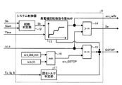
- FIG. 3 is a diagram illustrating a configuration example of the system controller.
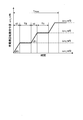
- FIG. 4 is a graph showing a generator rotation speed command value that changes with time.
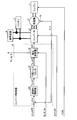
- FIG. 5 is a diagram showing a configuration example of the converter controller on the system configuration diagram of FIG.
- FIG. 6 is a diagram for explaining a first activation method in the vehicle control apparatus of the first embodiment.
- FIG. 7 is a diagram for explaining a second activation method in the vehicle control apparatus of the first embodiment.
- FIG. 1 is a diagram illustrating a configuration example of a vehicle drive system including a vehicle control device according to Embodiment 1 of the present invention.
- FIG. 2 is a diagram illustrating a configuration example of a fuel injection amount characteristic MAP provided in
- FIG. 8 is a diagram for explaining a third activation method in the vehicle control apparatus of the first embodiment.
- FIG. 9 is a diagram for explaining a fourth activation method in the vehicle control apparatus of the first embodiment.
- FIG. 10 is a diagram for explaining a fifth activation technique according to the second embodiment.
- FIG. 11 is a diagram for explaining a fifth activation technique according to the third embodiment.
- FIG. 1 is a diagram showing a configuration example of a vehicle drive system including a vehicle control device according to Embodiment 1 of the present invention, and shows a configuration when applied to a series hybrid type engine system. As shown in FIG.
- the vehicle drive system includes an engine 1, a generator 2 that is driven by the engine 1 and outputs AC power, a converter 3 that converts AC power into desired DC power, A load device 4 and a battery 5 electrically connected to the converter 3, a cab 6 that is operated when the driver performs vehicle control, an engine controller 7 that controls the engine 1, an engine controller 7, and a converter that will be described later
- the system controller 8 that controls the controller 9, the converter controller 9 that adjusts the power of the load device 4 and the battery 5, and the rotation speed detector 10 and the current sensor 11 as sensors are configured.
- the output shaft of the engine 1 and the rotor shaft of the generator 2 are mechanically coupled via a joint (not shown). For this reason, the rotation speed of the engine 1 (engine rotation speed) and the rotation speed of the generator 2 (generator rotation speed) coincide with each other.
- the engine 1 generates torque around the shaft (shaft torque) based on the fuel injection command FON from the engine controller 7.
- the generator 2 is, for example, a three-phase AC generator, and generates power by rotating with the driving force of the engine 1.
- the generator 2 can also operate as a motor. For example, power can be consumed by cranking the engine 1 when the engine 1 is started or by rotating the engine 1 using the driving force of the generator 2.
- the converter 3 is composed of a plurality of switching elements and rectifying elements not shown.
- the converter 3 receives the three-phase AC power output from the generator 2 and inputs the three-phase AC input based on the gate signal GP from the converter controller 9.
- the electric power is converted into desired DC power and supplied to one or both of the load device 4 and the battery 5.
- the generator 2 operates as a motor
- the DC power output from the battery 5 is converted into desired three-phase AC power based on the gate signal GP from the converter controller 9 to drive the generator 2.
- the gate cutoff signal GSTOP is input from the system controller 8
- the power conversion operation is stopped regardless of the presence or absence of the gate signal GP.
- the drive of the generator 2 can be stopped by the gate cutoff signal GSTOP from the system controller 8.
- the load device 4 is electrically connected to the converter 3 and operates upon receiving DC power from the converter 3.
- the components of the load device 4 are not shown, for example, an inverter device that converts DC power into AC power, an electric motor that outputs a driving force for accelerating a railway vehicle, etc., and an output of the electric motor is reduced. Consists of a reduction gear that transmits to the axle.
- the battery 5 is, for example, a lithium ion secondary battery, and stores the DC power supplied by the converter 3 and the regenerative power from the load device 4 while driving the generator 2 and the load device 4 using the stored power. To do.
- the battery 5 may have any configuration as long as it has a function of storing (charging) and discharging DC power.
- the driver's cab 6 is an operation device when the driver performs vehicle control as described above, and generates and outputs a vehicle start signal Start to the system controller 8 described later when the engine is started. At this time, the driver's cab 6 logs at a constant interval with the timing at which the vehicle activation signal Start is sent as 0 seconds, generates the logged information as an elapsed time Time, and sends it to the system controller 8.
- the engine controller 7 is a control unit that controls the engine 1 as described above. As shown in FIG. 2, the engine controller 7 is provided with a fuel injection characteristic MAP corresponding to the rotational speed of the engine 1. The engine controller 7 refers to the fuel injection command FON corresponding to the generator rotational speed ⁇ _c detected by the rotational speed detector 10 based on the engine start signal Se from the system controller 8 from the fuel injection characteristic MAP. The engine 1 is driven.
- the system controller 8 controls the engine controller 7, the converter controller 9, and the converter 3 in order to supply power to the load device 4 and the battery 5 and to start the engine 1.
- the rotational speed detector 10 detects the rotational speed ⁇ _c of the generator 2 and outputs the rotational speed ⁇ _c that is a detection signal to the engine controller 7, the system controller 8, and the converter controller 9.
- the current sensor 11 is connected between the three-phase lines of the generator 2 and the converter 3, detects the currents Iu, Iv, and Iw of each phase and outputs them to the converter controller 9. In FIG. 1, all the currents Iu, Iv, and Iw of each phase are detected, but it is not necessary to detect all the currents Iu, Iv, and Iw, and any two of these currents are detected. You may do it.
- the system controller 8 includes an activation determination unit 12, a generator rotation speed command value MAP13, comparators 14 to 16, and a regenerative torque determination unit 17.
- the start determination unit 12 receives a charge state Sb of the battery 5 and a vehicle start signal Start from the cab 6 and determines whether the engine 1 can be started based on the charge state Sb and the vehicle start signal Start.
- An engine start signal Sk is output. For example, if the battery charge state Sb is not an abnormal state and the vehicle start signal Start is ON, an engine start signal Sk instructing “ON” is output to the generator rotational speed command value MAP13.
- the generator rotation speed command value MAP 13 includes a predetermined generator corresponding to the elapsed time Time sent from the cab 6 and the engine start signal Sk sent from the start determination unit 12.
- the predetermined generator rotational speed command value ⁇ c_refN is stored so that the rotational speed command value ⁇ c_refN is output.
- the generator rotational speed command value ⁇ c_refN is set in a range lower than the idling rotational speed ⁇ e_idol of the engine 1.
- the generator rotational speed command value ⁇ c_refN is provided so as to reach the generator rotational speed command value ⁇ c_ref (N + 1), for example, after a certain time interval tN until the generator rotational speed command value ⁇ c_ref (N + 1). Yes.
- a method of providing a constant conversion rate ⁇ N between the generator rotational speed command value ⁇ c_refN and the generator rotational speed command value ⁇ c_ref (N + 1) may be considered.
- either method can be used in the sense of preventing a sudden generator rotational speed ⁇ _c. Needless to say, even when the natural number N is 1 or 2, the same setting method can be applied.
- the generator rotational speed command value ⁇ c_refN is set to maintain the generator rotational speed command value ⁇ c_ref (N + 1) for TN seconds from the time when the generator rotational speed command value ⁇ c_ref (N + 1) is reached. Even when the natural number N is 1 or 2, the generator rotation command value ⁇ c_refN is gradually increased while maintaining the time interval TN, and the timing for starting the fuel injection command FON from the engine controller 7 is waited for. become.
- the generator rotational speed command value MAP13 sequentially stores the elapsed time Time sent from the driver's cab 6 in an internal memory, and when this accumulated elapsed time Time exceeds the period upper limit value Tmax, the engine 1 is determined to have failed, and a gate cutoff signal GSTOP is output to the converter 3.
- the comparator 14 compares the generator rotational speed command value ⁇ c_refN sent from the generator rotational speed command value MAP 13 with the generator rotational speed ⁇ _c sent from the rotational speed detector 10. When the rotational speed command value ⁇ c_refN exceeds the generator rotational speed ⁇ _c, an engine start signal Se is output to the engine controller 7.
- the comparator 15 compares the generator rotational speed ⁇ _c sent from the rotational speed detector 10 with a generator gate cutoff rotational speed ⁇ c_GSTOP sent from the comparator 16 described later, and the generator rotational speed ⁇ _c is determined as the generator gate. When it coincides with the shut-off speed ⁇ c_GSTOP, the gate shut-off signal GSTOP is output to the converter 3.
- the comparator 16 compares the minimum idling maintenance speed ⁇ e_idol_min of the engine 1 with the engine speed threshold value ⁇ e_th, and outputs the smaller value to the comparator 15.
- the idling maintenance minimum rotational speed ⁇ e_idol_min is a rotational speed at which the engine 1 can rotate independently in consideration of variations in engine characteristics in the operating state and the maintenance state of the engine 1, and this rotational speed information is sequentially stored in the system controller 8. Is remembered.
- the engine speed threshold value ⁇ e_th is set to 550 rpm or the like.
- the regenerative torque determination unit 17 determines whether or not the generator 2 is performing a regenerative operation from any of the state quantities such as the torque component current It, the q-axis current Iq, and the estimated torque value Tc from the converter controller 9.
- the gate cutoff signal GSTOP is output. For example, if the sign of the torque estimation value Tc is negative, it is determined that the generator 2 is regenerating and outputs a gate cutoff signal GSTOP.
- the configuration of the converter controller 9 is as shown in FIG. As shown in FIG. 5, the converter controller 9 includes a voltage controller 18, a lower limit torque limiter 19, and a speed PI controller 20.
- the converter controller 9 calculates difference information ⁇ with respect to the generator rotational speed ⁇ _c acquired from the rotating shaft of the generator 2 with respect to the generator rotational speed command value ⁇ c_refN sent from the system controller 8. Thereafter, the speed PI controller 20 performs a proportional-integral calculation based on a gain set in advance based on a desired speed control response, and outputs the calculation result as a generator torque command value Tc_ref1.
- the generator torque command value Tc_ref1 is subjected to a lower limit process by the lower limit torque limiter 19, and is output to the voltage controller 18 as a generator torque command value Tc_ref2.
- the voltage controller 18 performs so-called vector control for causing the output torque of the generator 2 to follow the generator torque command value Tc_ref2, adjusts the voltage command to be output to the converter 3, and controls the internal voltage controller 18 according to the voltage command.
- the gate signal GP is generated and output by the PWM calculation at, and the converter 3 is driven. Note that the output torque of the generator 2 is controlled by driving the converter 3.
- the voltage controller 18 generates a torque component current It and a q-axis current Iq obtained in a vector control process using at least two of the currents Iu, Iv, and Iw of each phase detected from the current sensor 11. (Either one is acceptable) or information such as the estimated torque value Tc is sent to the system controller 8.
- the vector control in the voltage controller 18 since the various well-known methods can be used, detailed description here is abbreviate
- the control by the system controller 8 is as described above.
- the system controller 8 controls the engine 1 via the engine controller 7 and generates power via the converter controller 9 in accordance with the state of the battery 5 and the start signal from the cab 6.
- the machine 2 is controlled.
- the engine can be smoothly and reliably started up to the idling rotational speed ⁇ e_idol when the engine is started.
- the vehicle control apparatus Since the vehicle control apparatus according to the first embodiment has the above-described functions, the first to fourth activation methods as described below can be executed.
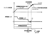
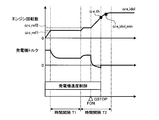
- FIG. 6 is a diagram for explaining a first activation method in the vehicle control apparatus of the first embodiment, in which time is plotted on the horizontal axis and engine speed, generator torque, and generator speed are plotted from the top on the vertical axis.
- the control section is shown.
- generator speed command values ⁇ c_ref 1 to N are output from the system controller 8 to the converter controller 9. Specifically, until the engine controller 7 controls the engine. Until the fuel injection command FON is output, the engine speed shown in FIG. 6 and the generator speed command value ⁇ c_ref1 shown in FIG. 4 are the same value.
- the engine 1 when the engine 1 establishes a driving force by its own fuel injection and starts rotating, the engine 1 accelerates to an idling rotational speed ⁇ e_idol that is a rotational speed higher than the generator rotational speed command value ⁇ c_ref1 by its own driving power. Therefore, in the converter controller 9, the generator torque command value Tc_ref1 is narrowed down by the action of the speed PI controller 20.
- the rotation speed threshold value ⁇ e_th is set between the generator rotation speed command value ⁇ c_ref1 and the idling maintenance minimum rotation speed ⁇ e_idol_min.
- a vehicle start signal Start which is an engine start command
- the converter controller 9 controls the generator 2 according to the signal from the system controller 8, and the generator 2 and the engine The number of rotations of 1 is controlled.
- the engine speed follows the generator rotational speed command value ⁇ c_ref1, and the generator torque is output as a torque value corresponding to the generator rotational speed command value ⁇ c_ref1.
- the gate cutoff signal GSTOP is output before the rotation speed threshold value ⁇ e_th is exceeded, and the drive of the generator 2 is stopped.
- the area (part K1 in the drawing) can be made very small. Thereby, when the engine is started, the generator torque and the engine torque hardly interfere with each other, so that the engine can be smoothly started up to the idling speed ⁇ e_idol. In addition, since the interference between the generator torque and the engine torque can be reduced, the engine can be started up smoothly and reliably.
- FIG. 7 is a diagram for explaining a second activation method in the vehicle control apparatus of the first embodiment.
- the generator rotational speed command value is provided in multiple stages and gradually increased at every time interval T. Specifically, in the example of FIG. 7, after setting the generator rotational speed command value to ⁇ c_ref1, the generator rotational speed command value is increased to ⁇ c_ref2 after the time interval T1, and when the generator rotational speed command value is ⁇ c_ref2 The fuel injection command FON is output.
- FIG. 8 is a diagram for explaining a third activation method in the vehicle control apparatus of the first embodiment.
- the period upper limit value Tmax is set in the rotational speed control of the generator 2.
- the generator 2 if the engine fuel injection command FON is not established even if the period upper limit value Tmax is exceeded and the engine speed has not increased to the idling speed ⁇ e_idol, the generator 2 is energized.
- a gate cut-off signal GSTOP is output to turn off.
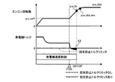
- FIG. 9 is a diagram for explaining a fourth activation method in the vehicle control apparatus of the first embodiment.
- the limit value of the lower limit torque limiter 19 (see FIG. 5) provided in the converter controller 9 is changed by two points on the time axis of FIG. Set to zero as shown by the line to inhibit regenerative action.
- the engine 1 can be started without generating regenerative torque corresponding to the area of K2 indicated by hatching, while preventing engine stall (so-called engine stall) It is possible to smoothly and reliably transition the engine 1 to the idling state.
- the fuel injection start command is used to set the rotation speed threshold value when the energization of the generator is forcibly controlled to be turned off.
- the generator power is controlled to turn off before the engine speed reaches the idling speed. The engine using the machine can be started smoothly and reliably.
- the generator rotation speed command values are provided in multiple stages, and the generator rotation speed command values provided in multiple stages are set at predetermined time intervals. Since the engine speed is gradually increased by selecting from the smaller one every time, even if the starting characteristic on the engine 1 side changes depending on the environmental temperature, the starting certainty is increased. It becomes possible.
- a predetermined period upper limit value is provided, and even if this period upper limit value is exceeded, engine fuel injection is not established, and engine rotation
- the generator power is controlled to be turned off. Therefore, it is possible to judge engine failure and malfunction, and to protect the engine from abnormal rotation conditions. It becomes possible.
- the lower limit torque limiter is provided on the input side of the converter controller, and the regenerative operation at the time of starting the engine is suppressed.
- the engine 1 can be smoothly and reliably transitioned to the idling state while preventing the engine from stalling.
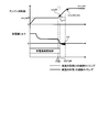
- FIG. FIG. 10 is a diagram for explaining the activation method (fifth activation method) according to the second embodiment.
- the fifth activation method is different from the fourth activation method according to the first embodiment in the timing at which the system controller 8 transmits the gate cutoff signal GSTOP to the converter 3.
- the voltage controller 18 (see FIG. 5) provided in the converter controller 9 uses at least two of the currents Iu, Iv, and Iw detected by the current sensor 11 in FIG. A gate signal GP to be controlled is generated.
- the control executed by the voltage controller 18 is called vector control. When this vector control is performed, the torque current It is recognized. For this reason, it is possible to determine the power running / regeneration based on the sign of the torque component current It.
- This function is executed by a regenerative torque determination unit 17 provided in the system controller 8 as shown in FIG.
- the regenerative torque determination unit 17 determines power running / regeneration based on the sign of the torque divided current It, generates a gate cutoff signal GSTOP at a timing when the generator torque is switched to the regenerative torque, outputs it to the converter 3, and energizes the generator 2 Turn off.
- the engine 1 can be started without generating regenerative torque corresponding to the area of K3 indicated by hatching, and the engine 1 can smoothly transition to the idling state while preventing engine stall (so-called engine stall). And it becomes possible to execute reliably.
- FIG. FIG. 11 is a diagram for explaining the activation method (sixth activation method) according to the third embodiment.
- the sixth starting method is different from the fifth starting method according to the second embodiment in detection means for detecting the regenerative torque. More specifically, in the third embodiment, a torque detector 21 is provided on the rotating shaft connecting the engine 1 and the generator 2, and the value of the generator shaft torque Tck is detected from the torque detector 21.
- the generator shaft torque Tck is transmitted to the regenerative torque determination unit 17 of the system controller 8, and the regenerative torque determination unit 17 determines whether or not there is a regenerative operation.
- the subsequent operation is the same as that of the second embodiment, and detailed description thereof is omitted.
- the presence or absence of the regenerative operation in the generator 2 is determined based on the generator shaft torque Tck detected by the torque detector 21.
- the gate cut-off signal GSTOP is generated and output to the converter 3, and the energization of the generator 2 is controlled to be turned off, so that the engine 1 is brought into an idling state while preventing engine stall. It is possible to smoothly and reliably execute the transition.
- the configurations shown in the first and second embodiments are examples of the configuration of the present invention, and can be combined with other known techniques, and can be combined within a range not departing from the gist of the present invention. Needless to say, the configuration may be modified by omitting the unit.
- the present invention is useful as a vehicle control apparatus and a railway hybrid vehicle control method capable of smoothly and reliably starting an engine using a generator.
Landscapes
- Engineering & Computer Science (AREA)
- Transportation (AREA)
- Mechanical Engineering (AREA)
- Chemical & Material Sciences (AREA)
- Combustion & Propulsion (AREA)
- Automation & Control Theory (AREA)
- Hybrid Electric Vehicles (AREA)
- Electric Propulsion And Braking For Vehicles (AREA)
- Control Of Vehicle Engines Or Engines For Specific Uses (AREA)
Abstract
Description
図1は、本発明の実施の形態1に係る車両制御装置を含む車両駆動システムの一構成例を示す図であり、シリーズハイブリッド方式のエンジンシステムに適用した場合の構成を示している。図1に示すように、実施の形態1に係る車両駆動システムは、エンジン1、エンジン1によって駆動され、交流電力を出力する発電機2、交流電力を所望の直流電力に変換するコンバータ3と、コンバータ3と電気的に接続された負荷装置4およびバッテリ5、運転手が車両制御を行う際に操作をおこなう運転台6、エンジン1を制御するエンジン制御器7、エンジン制御器7および後述するコンバータ制御器9を制御するシステム制御器8、負荷装置4およびバッテリ5の電力調整を行うコンバータ制御器9ならびに、センサ類として、回転速度検出器10および電流センサ11を備えて構成される。
図6は、実施の形態1の車両制御装置における第1の起動手法を説明する図であり、横軸には時間をとり、縦軸には上からエンジン回転数、発電機トルクおよび発電機速度制御区間を示している。なお、図1において、システム制御器8からコンバータ制御器9に対しては発電機回転数指令値ωc_ref1~Nが出力されるが、エンジン制御器7がエンジンを制御するまでの間、具体的には、燃料噴射指令FONが出力されるまでの間においては、図6に表記しているエンジン回転数と図4に表記している発電機回転数指令値ωc_ref1とは同一の値になる。一方、エンジン1が自身の燃料噴射により駆動力を確立し回転するようになると、エンジン1が自身の駆動力により、発電機回転数指令値ωc_ref1より高い回転数であるアイドリング回転数ωe_idolまで加速到達しようとするため、コンバータ制御器9においては速度PI制御器20の作用により発電機トルク指令値Tc_ref1が絞りこまれる。
図7は、実施の形態1の車両制御装置における第2の起動手法を説明する図である。この図7に示す第2の起動手法では、発電機回転数指令値を多段に設け、時間間隔T毎に徐々に上げるようにしている。具体的に、図7の例では、発電機回転数指令値をωc_ref1に設定した後、時間間隔T1後に発電機回転数指令値をωc_ref2に上昇させ、発電機回転数指令値がωc_ref2のときに燃料噴射指令FONを出力している。この制御により、例えば寒冷時において、エンジン1の潤滑状態が悪く、発電機回転数指令値ωc_ref1ではエンジン1の起動ができない場合でも、発電機回転数指令値をωc_ref2に上昇させてエンジン1の起動を開始することができる。すなわち、エンジン1側の起動特性が環境温度に依存して変化する場合であっても、起動の確実性が増すという効果がある。
図8は、実施の形態1の車両制御装置における第3の起動手法を説明する図である。この図8に示す第3の起動手法では、発電機2の回転数制御において期間上限値Tmaxを設定するようにしている。具体的に、図8の例では、期間上限値Tmaxを超えてもエンジンの燃料噴射指令FONが確立せずエンジン回転数がアイドリング回転数ωe_idolまで上昇しなかった場合には、発電機2の通電をオフするためにゲート遮断信号GSTOPを出力する。この制御により、エンジン1の故障および不具合を判定し、異常な回転状態を脱してエンジン1を保護することが可能となる。
図9は、実施の形態1の車両制御装置における第4の起動手法を説明する図である。この第4の起動手法では、発電機2の回転数制御を行う場合に、コンバータ制御器9に設けられた下限トルクリミッタ19(図5参照)のリミット値を図9の時間軸上に二点差線で示すように零に設定して回生動作を抑止する。この制御により、発電機トルクが零を下回ることがなくなるため、ハッチングで示したK2の面積分の回生トルクを生じさせずにエンジン1を起動できるので、エンジンストール(所謂エンスト)を防止しつつ、エンジン1のアイドリング状態への遷移を円滑且つ確実に行うことが可能となる。
図10は、実施の形態2に係る起動手法(第5の起動手法)を説明する図である。この第5の起動手法は、実施の形態1に係る第4の起動手法と比較して、システム制御器8からコンバータ3に対してゲート遮断信号GSTOPを伝送するタイミングが異なっている。コンバータ制御器9に設けられた電圧制御器18(図5参照)は、図1の電流センサ11が検出した各相の電流Iu、Iv、Iwのうちの少なくとも2つを用いて、コンバータ3を制御するゲート信号GPを生成する。電圧制御器18が実行する制御はベクトル制御と呼ばれているが、このベクトル制御を行うときには、トルク分電流Itが認識されている。このため、トルク分電流Itの符号により力行/回生の判別が可能となる。なお、この機能は、図3に示すように、システム制御器8に設けた回生トルク判定部17が実行する。回生トルク判定部17は、トルク分電流Itの符号により力行/回生を判別し、発電機トルクが回生トルクに切り替わるタイミングでゲート遮断信号GSTOPを生成してコンバータ3に出力し、発電機2に対する通電をオフする。この制御により、ハッチングで示したK3の面積分の回生トルクを生じさせずにエンジン1を起動することができ、エンジンストール(所謂エンスト)を防止しつつ、エンジン1のアイドリング状態への遷移を円滑且つ確実に実行することが可能となる。
図11は、実施の形態3に係る起動手法(第6の起動手法)を説明する図である。この第6の起動手法は、実施の形態2に係る第5の起動手法と比較して、回生トルクを検出する検出手段が異なっている。具体的に説明すると、実施の形態3では、エンジン1と発電機2とを繋ぐ回転軸にトルク検出器21を設け、このトルク検出器21から発電機軸トルクTckの値を検出する。この発電機軸トルクTckは、システム制御器8の回生トルク判定部17に伝送され、回生トルク判定部17にて回生動作の有無が判定される。なお、これ以降の動作は、実施の形態2と同様であり、詳細な説明は省略する。
2 発電機
3 コンバータ
4 負荷装置
5 バッテリ
6 運転台
7 エンジン制御器
8 システム制御器
9 コンバータ制御器
10 回転速度検出器
11 電流センサ
12 起動判定部
13 発電機回転数指令値MAP
14~16 比較器
17 回生トルク判定部
18 電圧制御器
19 下限トルクリミッタ
20 速度PI制御器
21 トルク検出器
Claims (8)
- エンジンと、エンジンの動作を制御するエンジン制御器と、前記エンジンに連結される発電機と、前記発電機が出力する交流電力を所望の直流電力に変換するコンバータと、前記コンバータの動作を制御するコンバータ制御器と、前記コンバータから直流電力の供給を受けて動作する負荷装置と、前記発電機の回転速度を検出する回転速度検出器と、前記負荷装置と前記発電機とに電気的に接続されたバッテリと、を備えた車両駆動システムに適用され、前記エンジンの起動を制御可能に構成される車両制御装置であって、
前記エンジン制御器、前記コンバータ制御器および前記コンバータを統括的に制御するシステム制御器が設けられ、
前記システム制御器は、
前記コンバータ制御器を通じて前記エンジンのアイドリング維持回転数よりも小さな回転数指令値で前記発電機を駆動すると共に、所定時間の経過後に前記エンジン制御器を通じて前記エンジンに対する燃料噴射を開始し、前記エンジンの回転数が前記回転数指令値よりも大きく、且つ、前記アイドリング維持回転数よりも小さい所定の閾値に到達すると前記発電機の通電をオフする制御信号を前記コンバータに出力することを特徴とする車両制御装置。 - 前記回転数指令値として、複数個の指令値が多段に設けられており、
前記システム制御器は、前記多段に設けた回転数指令値を所定の時間間隔毎に小さい方から順次選択して前記発電機を駆動することを特徴とする請求項1に記載の車両制御装置。 - 前記発電機の制御には、期間上限値が設定されており、前記期間上限値を超えても前記エンジンの燃料噴射が確立せず、且つ、前記エンジンの回転数が前記アイドリング維持回転数まで到達しなかった場合に、前記発電機の通電をオフすることを特徴とする請求項1または2に記載の車両制御装置。
- 前記コンバータには、前記発電機に対するトルク指令の下限値をリミットする下限トルクリミッタが設けられ、
前記下限トルクリミッタは、前記エンジンの起動時における回生動作を抑止することを特徴する請求項1に記載の車両制御装置。 - 前記エンジンと前記発電機とを繋ぐ回転軸にはトルク検出器が設けられており、
前記システム制御器は、前記トルク検出器が検出したトルク値に基づいて前記発電機における回生動作の有無を判定し、回生動作が生じていると判定した場合に前記発電機の通電をオフする制御信号を前記コンバータに出力することを特徴とする請求項1に記載の車両制御装置。 - エンジンと、エンジンの動作を制御するエンジン制御器と、前記エンジンに連結される発電機と、前記発電機が出力する交流電力を所望の直流電力に変換するコンバータと、前記コンバータの動作を制御するコンバータ制御器と、前記コンバータから直流電力の供給を受けて動作する負荷装置と、前記負荷装置と前記発電機とに電気的に接続されたバッテリと、を備えた鉄道用ハイブリッド車両の制御方法であって、
前記コンバータ制御器を通じて前記エンジンのアイドリング維持回転数よりも小さな回転数指令値で前記発電機を駆動する第1ステップと、
所定時間の経過後に前記エンジン制御器を通じて前記エンジンに対する燃料噴射を開始する第2ステップと、
前記エンジンの回転数が前記回転数指令値よりも大きく、且つ、前記アイドリング維持回転数よりも小さい所定の閾値に到達すると前記発電機の通電をオフする制御信号を前記コンバータに出力する第3ステップと、
を含むことを特徴とする鉄道用ハイブリッド車両の制御方法。 - 前記第1ステップには、多段に設けた回転数指令値を所定の時間間隔毎に小さい方から順次選択して前記発電機を駆動するサブステップが含まれることを特徴とする請求項6に記載の鉄道用ハイブリッド車両の制御方法。
- 前記発電機の制御には、期間上限値が設定されており、この期間上限値を超えても前記第2のステップにおける燃料噴射が確立せず、且つ、前記エンジンの回転数が前記アイドリング維持回転数まで到達しなかった場合には、前記第3のステップの条件が満足しない場合でも前記発電機の通電をオフに制御することを特徴とする請求項6または7に記載の鉄道用ハイブリッド車両の制御方法。
Priority Applications (6)
| Application Number | Priority Date | Filing Date | Title |
|---|---|---|---|
| US14/368,450 US9199651B2 (en) | 2012-01-31 | 2012-01-31 | Vehicle control apparatus and control method for hybrid vehicle for railroad |
| CN201280068374.6A CN104080677B (zh) | 2012-01-31 | 2012-01-31 | 车辆控制装置及铁路用混合动力车辆的控制方法 |
| EP12867351.4A EP2810838B1 (en) | 2012-01-31 | 2012-01-31 | Vehicle control apparatus, and method of controlling railroad hybrid vehicle |
| KR1020147020600A KR101565273B1 (ko) | 2012-01-31 | 2012-01-31 | 차량 제어 장치 및 철도용 하이브리드 차량의 제어 방법 |
| PCT/JP2012/052181 WO2013114575A1 (ja) | 2012-01-31 | 2012-01-31 | 車両制御装置および鉄道用ハイブリッド車両の制御方法 |
| JP2012542293A JP5220242B1 (ja) | 2012-01-31 | 2012-01-31 | 車両制御装置および鉄道用ハイブリッド車両の制御方法 |
Applications Claiming Priority (1)
| Application Number | Priority Date | Filing Date | Title |
|---|---|---|---|
| PCT/JP2012/052181 WO2013114575A1 (ja) | 2012-01-31 | 2012-01-31 | 車両制御装置および鉄道用ハイブリッド車両の制御方法 |
Publications (1)
| Publication Number | Publication Date |
|---|---|
| WO2013114575A1 true WO2013114575A1 (ja) | 2013-08-08 |
Family
ID=48778736
Family Applications (1)
| Application Number | Title | Priority Date | Filing Date |
|---|---|---|---|
| PCT/JP2012/052181 WO2013114575A1 (ja) | 2012-01-31 | 2012-01-31 | 車両制御装置および鉄道用ハイブリッド車両の制御方法 |
Country Status (6)
| Country | Link |
|---|---|
| US (1) | US9199651B2 (ja) |
| EP (1) | EP2810838B1 (ja) |
| JP (1) | JP5220242B1 (ja) |
| KR (1) | KR101565273B1 (ja) |
| CN (1) | CN104080677B (ja) |
| WO (1) | WO2013114575A1 (ja) |
Families Citing this family (5)
| Publication number | Priority date | Publication date | Assignee | Title |
|---|---|---|---|---|
| JP6084914B2 (ja) * | 2013-09-24 | 2017-02-22 | トヨタ自動車株式会社 | 電力供給システム |
| FR3012771B1 (fr) * | 2013-11-04 | 2016-01-15 | Continental Automotive France | Procede de prevention de calage d'un moteur utilisant une estimation de vitesse de rotation dudit moteur |
| US9828965B2 (en) * | 2016-01-21 | 2017-11-28 | GM Global Technology Operations LLC | Method and apparatus to evaluate a starter motor for an internal combustion engine |
| CN109955846B (zh) * | 2017-12-22 | 2021-03-26 | 比亚迪股份有限公司 | 混合动力汽车及其电机的控制方法和装置 |
| JP2023022849A (ja) * | 2021-08-04 | 2023-02-16 | 国立研究開発法人宇宙航空研究開発機構 | 発電システムおよび航空機 |
Citations (4)
| Publication number | Priority date | Publication date | Assignee | Title |
|---|---|---|---|---|
| JP2001059437A (ja) * | 1999-08-19 | 2001-03-06 | Nissan Motor Co Ltd | エンジンの自動停止再始動装置 |
| JP3890459B2 (ja) | 1999-05-14 | 2007-03-07 | 日産自動車株式会社 | エンジン自動停止再始動車両 |
| JP2008296907A (ja) * | 1999-03-29 | 2008-12-11 | Toyota Motor Corp | ハイブリッド型の車両用駆動システム |
| JP2009029397A (ja) * | 2007-06-25 | 2009-02-12 | Mazda Motor Corp | ハイブリッド車両の制御装置および制御方法 |
Family Cites Families (13)
| Publication number | Priority date | Publication date | Assignee | Title |
|---|---|---|---|---|
| JPH10331749A (ja) | 1997-06-03 | 1998-12-15 | Nissan Motor Co Ltd | 車両のハイブリッドパワートレーンシステム |
| DE19852085C1 (de) * | 1998-11-12 | 2000-02-17 | Daimler Chrysler Ag | Starteinrichtung für eine Brennkraftmaschine und Verfahren zum Starten der Brennkraftmaschine |
| JP3347080B2 (ja) | 1998-12-18 | 2002-11-20 | 本田技研工業株式会社 | ハイブリッド車の始動判定装置 |
| EP1052400B1 (en) | 1999-05-12 | 2004-10-27 | Nissan Motor Company, Limited | Automatic stop-restart system of automotive internal combustion engine |
| JP4314751B2 (ja) | 2001-04-16 | 2009-08-19 | 株式会社デンソー | 充電システムおよび車両用発電制御装置 |
| KR100456851B1 (ko) * | 2002-07-31 | 2004-11-10 | 현대자동차주식회사 | 직렬형 하이브리드 차량의 보조 동력 제어장치 |
| US7028657B2 (en) * | 2004-05-14 | 2006-04-18 | General Motors Corporation | Multi-stage compression ignition engine start |
| EP2008860B1 (en) * | 2007-06-25 | 2015-06-17 | Mazda Motor Corporation | Control for hybrid electric vehicle |
| JP2009184500A (ja) | 2008-02-06 | 2009-08-20 | Toyota Motor Corp | 車両およびその制御方法 |
| JP5223603B2 (ja) | 2008-11-04 | 2013-06-26 | 日産自動車株式会社 | ハイブリッド車両の制御装置 |
| DE102010025183A1 (de) * | 2010-06-26 | 2011-12-29 | Daimler Ag | Verfahren und Vorrichtung zum Starten eines Verbrennungsmotors |
| CN202076981U (zh) * | 2010-08-13 | 2011-12-14 | 湖南南车时代电动汽车股份有限公司 | 一种混合动力车用发电机控制器 |
| CN202081970U (zh) * | 2011-03-31 | 2011-12-21 | 潘世澄 | 混合动力电动车燃油发电机组 |
-
2012
- 2012-01-31 JP JP2012542293A patent/JP5220242B1/ja not_active Expired - Fee Related
- 2012-01-31 EP EP12867351.4A patent/EP2810838B1/en active Active
- 2012-01-31 WO PCT/JP2012/052181 patent/WO2013114575A1/ja active Application Filing
- 2012-01-31 CN CN201280068374.6A patent/CN104080677B/zh not_active Expired - Fee Related
- 2012-01-31 KR KR1020147020600A patent/KR101565273B1/ko active IP Right Grant
- 2012-01-31 US US14/368,450 patent/US9199651B2/en not_active Expired - Fee Related
Patent Citations (4)
| Publication number | Priority date | Publication date | Assignee | Title |
|---|---|---|---|---|
| JP2008296907A (ja) * | 1999-03-29 | 2008-12-11 | Toyota Motor Corp | ハイブリッド型の車両用駆動システム |
| JP3890459B2 (ja) | 1999-05-14 | 2007-03-07 | 日産自動車株式会社 | エンジン自動停止再始動車両 |
| JP2001059437A (ja) * | 1999-08-19 | 2001-03-06 | Nissan Motor Co Ltd | エンジンの自動停止再始動装置 |
| JP2009029397A (ja) * | 2007-06-25 | 2009-02-12 | Mazda Motor Corp | ハイブリッド車両の制御装置および制御方法 |
Non-Patent Citations (1)
| Title |
|---|
| See also references of EP2810838A4 |
Also Published As
| Publication number | Publication date |
|---|---|
| KR101565273B1 (ko) | 2015-11-02 |
| CN104080677A (zh) | 2014-10-01 |
| CN104080677B (zh) | 2016-10-19 |
| EP2810838B1 (en) | 2023-04-19 |
| EP2810838A4 (en) | 2016-10-19 |
| JPWO2013114575A1 (ja) | 2015-05-11 |
| JP5220242B1 (ja) | 2013-06-26 |
| EP2810838A1 (en) | 2014-12-10 |
| KR20140105604A (ko) | 2014-09-01 |
| US20140350757A1 (en) | 2014-11-27 |
| US9199651B2 (en) | 2015-12-01 |
Similar Documents
| Publication | Publication Date | Title |
|---|---|---|
| JP3540209B2 (ja) | ハイブリッド車両の制御装置 | |
| US9469185B2 (en) | Control device for hybrid vehicle | |
| US20100210411A1 (en) | Clutch Engaging Control Method and Control System in Hybrid Power Output Device | |
| JP5220242B1 (ja) | 車両制御装置および鉄道用ハイブリッド車両の制御方法 | |
| US10166870B2 (en) | Hybrid vehicle and control method for hybrid vehicle | |
| US10611365B2 (en) | Hybrid vehicle and method of controlling the same | |
| CN110466499B (zh) | 用于驱动混合动力车辆的方法和系统 | |
| JP2009227078A (ja) | 動力システムおよびその制御方法並びに車両 | |
| KR101646419B1 (ko) | 하이브리드 차량의 비상 운전 방법 | |
| US8736235B2 (en) | Power generation motor control system | |
| JP7459752B2 (ja) | 回生制御方法及び回生制御装置 | |
| KR101994303B1 (ko) | 하이브리드 자동차 및 그 제어 방법 | |
| US9000700B2 (en) | Motor control apparatus | |
| KR101113646B1 (ko) | 하이브리드 차량의 림프홈 운전 방법 | |
| JP6618308B2 (ja) | 車両用制御装置 | |
| KR102394863B1 (ko) | 페일 세이프 주행유지방법 및 하이브리드 차량 | |
| JP7290026B2 (ja) | 電動機の制御装置 | |
| JP3993158B2 (ja) | ハイブリッド自動車 | |
| JP2021162067A (ja) | 油圧制御システム | |
| JP2020028138A (ja) | 回転電機の制御装置 | |
| WO2018105407A1 (ja) | 回転電機制御装置 | |
| CN116056943A (zh) | 用于诊断混合动力传动系的电池继电器断开的方法 | |
| JP2006280111A (ja) | ハイブリッド電気自動車用エンジン制御装置 |
Legal Events
| Date | Code | Title | Description |
|---|---|---|---|
| ENP | Entry into the national phase |
Ref document number: 2012542293 Country of ref document: JP Kind code of ref document: A |
|
| 121 | Ep: the epo has been informed by wipo that ep was designated in this application |
Ref document number: 12867351 Country of ref document: EP Kind code of ref document: A1 |
|
| WWE | Wipo information: entry into national phase |
Ref document number: 14368450 Country of ref document: US |
|
| ENP | Entry into the national phase |
Ref document number: 20147020600 Country of ref document: KR Kind code of ref document: A |
|
| WWE | Wipo information: entry into national phase |
Ref document number: 2012867351 Country of ref document: EP |
|
| NENP | Non-entry into the national phase |
Ref country code: DE |