WO2013108602A1 - 歯科用ハンドピースの制御装置 - Google Patents
歯科用ハンドピースの制御装置 Download PDFInfo
- Publication number
- WO2013108602A1 WO2013108602A1 PCT/JP2013/000091 JP2013000091W WO2013108602A1 WO 2013108602 A1 WO2013108602 A1 WO 2013108602A1 JP 2013000091 W JP2013000091 W JP 2013000091W WO 2013108602 A1 WO2013108602 A1 WO 2013108602A1
- Authority
- WO
- WIPO (PCT)
- Prior art keywords
- rotation angle
- rotation
- motor
- load torque
- dental handpiece
- Prior art date
Links
Images


Classifications
-
- A—HUMAN NECESSITIES
- A61—MEDICAL OR VETERINARY SCIENCE; HYGIENE
- A61C—DENTISTRY; APPARATUS OR METHODS FOR ORAL OR DENTAL HYGIENE
- A61C1/00—Dental machines for boring or cutting ; General features of dental machines or apparatus, e.g. hand-piece design
- A61C1/0007—Control devices or systems
- A61C1/0015—Electrical systems
- A61C1/003—Control of rotation of instrument
-
- A—HUMAN NECESSITIES
- A61—MEDICAL OR VETERINARY SCIENCE; HYGIENE
- A61C—DENTISTRY; APPARATUS OR METHODS FOR ORAL OR DENTAL HYGIENE
- A61C5/00—Filling or capping teeth
- A61C5/40—Implements for surgical treatment of the roots or nerves of the teeth; Nerve needles; Methods or instruments for medication of the roots
- A61C5/42—Files for root canals; Handgrips or guiding means therefor
-
- A—HUMAN NECESSITIES
- A61—MEDICAL OR VETERINARY SCIENCE; HYGIENE
- A61C—DENTISTRY; APPARATUS OR METHODS FOR ORAL OR DENTAL HYGIENE
- A61C1/00—Dental machines for boring or cutting ; General features of dental machines or apparatus, e.g. hand-piece design
- A61C1/02—Dental machines for boring or cutting ; General features of dental machines or apparatus, e.g. hand-piece design characterised by the drive of the dental tools
- A61C1/06—Dental machines for boring or cutting ; General features of dental machines or apparatus, e.g. hand-piece design characterised by the drive of the dental tools with electric drive
-
- A—HUMAN NECESSITIES
- A61—MEDICAL OR VETERINARY SCIENCE; HYGIENE
- A61C—DENTISTRY; APPARATUS OR METHODS FOR ORAL OR DENTAL HYGIENE
- A61C1/00—Dental machines for boring or cutting ; General features of dental machines or apparatus, e.g. hand-piece design
- A61C1/08—Machine parts specially adapted for dentistry
- A61C1/18—Flexible shafts; Clutches or the like; Bearings or lubricating arrangements; Drives or transmissions
- A61C1/185—Drives or transmissions
- A61C1/186—Drives or transmissions with torque adjusting or limiting means
-
- A—HUMAN NECESSITIES
- A61—MEDICAL OR VETERINARY SCIENCE; HYGIENE
- A61C—DENTISTRY; APPARATUS OR METHODS FOR ORAL OR DENTAL HYGIENE
- A61C19/00—Dental auxiliary appliances
- A61C19/04—Measuring instruments specially adapted for dentistry
- A61C19/042—Measuring instruments specially adapted for dentistry for determining the position of a root apex
-
- A—HUMAN NECESSITIES
- A61—MEDICAL OR VETERINARY SCIENCE; HYGIENE
- A61C—DENTISTRY; APPARATUS OR METHODS FOR ORAL OR DENTAL HYGIENE
- A61C5/00—Filling or capping teeth
- A61C5/40—Implements for surgical treatment of the roots or nerves of the teeth; Nerve needles; Methods or instruments for medication of the roots
-
- F—MECHANICAL ENGINEERING; LIGHTING; HEATING; WEAPONS; BLASTING
- F04—POSITIVE - DISPLACEMENT MACHINES FOR LIQUIDS; PUMPS FOR LIQUIDS OR ELASTIC FLUIDS
- F04C—ROTARY-PISTON, OR OSCILLATING-PISTON, POSITIVE-DISPLACEMENT MACHINES FOR LIQUIDS; ROTARY-PISTON, OR OSCILLATING-PISTON, POSITIVE-DISPLACEMENT PUMPS
- F04C2270/00—Control; Monitoring or safety arrangements
- F04C2270/04—Force
- F04C2270/042—Force radial
- F04C2270/0421—Controlled or regulated
Definitions
- the present invention relates to a control device for a dental handpiece for cutting a tooth root canal.
- a dental handpiece for cutting a tooth root canal is configured to rotate a cutting tool called a file with a motor.
- the file for cutting the root canal of the tooth has an elongated shape. If the file bites into the teeth during cutting of the root canal of the tooth, a force in the torsional direction acts on the file, with the result that the file tends to break.
- forward / reverse rotation in which the file is rotated in one direction for a certain period of time and then rotated in the opposite direction, it is transferred to the root canal of the file.
- forward rotation and reverse rotation have been proposed a technique for preventing bite and breakage (see, for example, Patent Document 1).
- repeating forward rotation and reverse rotation in this way may be called reciprocating rotation.
- forward rotation and reverse rotation do not refer to rotation in a specific direction, but merely refer to the direction of preceding rotation as normal rotation.
- the file is rotated clockwise or counterclockwise by a desired first rotation angle, and then the second rotation is performed in a direction opposite to the first rotation angle. Rotate by an angle.
- the first rotation angle is larger than the second rotation angle so that, when the file advances during the cleaning of the root canal, the cut pieces removed from the root canal are discharged upward from the surface of the root canal. is doing.
- the first rotation angle and the second rotation angle are fixed to preset values such as 120 degrees and 90 degrees, respectively. Therefore, even if the load increases, the file continues to rotate until the set angle is reached, so the file may bite into the root canal, which may lead to file breakage.
- the present invention has been made based on such a technical problem, and an object of the present invention is to provide a dental handpiece control device capable of preventing a file for reciprocating rotation from biting into a root canal.
- the control device for a dental handpiece includes a voltage applied to a motor for rotating a cutting tool (file) mounted in the dental handpiece and mounted on the dental handpiece.
- a rotation direction switching unit that switches the rotation direction of the motor to normal rotation and reverse rotation by switching the polarity of the motor, and a rotation angle ⁇ F during forward rotation of the motor associated with the state information of the cutting tool and a rotation angle ⁇ during reverse rotation
- a control unit that controls switching of the polarity of the voltage of the rotation direction switching unit based on R.
- the rotation angle ⁇ F during forward rotation and the rotation angle ⁇ R during reverse rotation are set to values that prevent the cutting tool in the state from biting into the root canal. Can be prevented from biting into the root canal.
- the rotation angle ⁇ F during forward rotation refers to the rotation angle during one cycle of forward rotation
- the rotation angle ⁇ R during reverse rotation refers to the rotation angle during one cycle of reverse rotation.
- the state information of the cutting tool can be a load torque of the motor.
- the control unit on the basis of the rotation angle theta F and the rotation angle theta R associated with the load torque, it is preferable to control the switching of the polarity of the voltage of the rotational direction switching unit. This is because the load torque of the motor can most significantly indicate the biting of the cutting tool in the state information of the cutting tool.
- the motor load torque and the rotation angle ⁇ F , and the motor load torque and the rotation angle ⁇ R can be in a proportional relationship.
- the reference value in the load torque of the motor may be different from the angle of rotation theta F and the rotation angle theta R.
- a dental handpiece control device that can prevent a cutting tool (file) that performs reciprocating rotation from biting into the root canal.
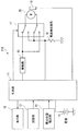
- a control device 10 for a dental handpiece (hereinafter simply referred to as a handpiece) is for controlling the operation of a motor 20 incorporated in a handpiece (not shown).
- the control unit 11 is a computer unit including a CPU, a memory, and the like.
- the display unit 12 includes a monitor, an indicator lamp, and the like that display information indicating the rotation speed and load torque as the operation status of the motor 20 and information for performing the operation setting of the motor 20 by the control unit 11.
- the setting unit 13 sets operating conditions such as the rotation speed, torque, and rotation angle of the motor 20 to the control unit 11 and holds the setting information.
- the setting unit 13 of the present embodiment holds setting information related to the rotation angle ⁇ F when the motor 20 is rotated forward and the rotation angle ⁇ R when the motor 20 is rotated backward.
- the power supply 14 supplies power for causing the handpiece control device 10 and the motor 20 to function.
- the drive unit 15 adjusts a voltage value applied to the motor 20 based on a command from the control unit 11.
- the sensor 16 includes a hall element and an encoder that detect the rotation angle of the motor 20.
- the relay 17 switches the voltage application polarity to the motor 20.
- the current detection resistor 18 detects the current that has passed through the relay 17, converts the current (motor current) that flows through the motor 20 into a voltage, and feeds it back to the control unit 11.
- the control unit 11 can measure the load torque of the motor 20 based on the fed back voltage value.
- a brushless DC motor can be used, for example.
- the control device 10 executes the following control based on a preset computer program.
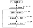
- application of a voltage to the motor 20 is started by a command from the control unit 11 (step S101).
- the control unit 11 detects the rotation speed of the motor with the sensor 16, and the detected value matches the set value (set speed) of the rotation speed of the motor 20 set in advance in the setting unit 13.
- the voltage applied to 20 is adjusted.
- the control unit 11 measures the load torque via the current detection resistor 18 (step S103). Based on the measured load torque, the control unit 11 sets the rotation angle ⁇ F when the motor 20 rotates forward and the rotation angle ⁇ R when the motor 20 rotates backward according to the load torque (step S105, 107).
- the rotation angle is set by referring to information stored in advance in the setting unit 13 as described above. An example of the information will be described with reference to FIG.
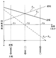
- the horizontal axis represents the load torque
- the vertical axis represents the rotation angle ⁇ .
- the rotation angle ⁇ F during forward rotation decreases as the load torque increases, and conversely, the rotation angle ⁇ R during reverse rotation increases in proportion to the load torque.
- the rotation angle ⁇ F for example, 150 degrees
- the rotation angle ⁇ R for example, 30 degrees.
- the load torque T2 > T1
- the emphasis is placed on the balance between cutting and discharge of the cut piece, and the rotation angle ⁇ F (for example, 90 degrees) and the rotation angle ⁇ R (for example, 90 degrees) are made the same. Yes.
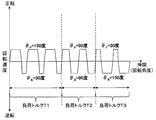
- FIG. 4 shows how the motor 20 is rotated in the example of the above rotation angle ⁇ F (150 degrees, 90 degrees, 30 degrees) and rotation angle ⁇ R (30 degrees, 90 degrees, 150 degrees).
- control device 10 determines the rotation angle ⁇ F during forward rotation and the rotation angle ⁇ R during reverse rotation according to the magnitude of the load torque, and thus reduces the biting of the file. The breakage can be prevented.
- the reference torque is set and held in advance in the setting unit 13, and the control unit 11 compares the measured load torque with this reference torque (step S205). If the load torque is less than the reference torque (step S205 Yes), the first forward rotation angle ⁇ F1 and the first reverse rotation angle ⁇ R1 are set (steps S207 and 209). On the other hand, if the load torque is the reference torque or more (step S205 No), the second normal rotation angle theta F2 and the second reverse rotation angle theta R2 is set (step S211,213).
- FIG. 6 An example of the first forward rotation angle ⁇ F1 , the first reverse rotation angle ⁇ R1 , the second normal rotation angle ⁇ F2, and the second reverse rotation angle ⁇ R2 is shown in FIG.
- the second forward rotation angle ⁇ F2 is set smaller than the first forward rotation angle ⁇ F1 with the reference torque Tr as a boundary.
- second reverse rotation angle theta R2 is set larger than the reverse rotation angle theta R1. That is, also in the second embodiment, when the load torque is small, the forward rotation angle is increased, and when the load torque is large, the reverse rotation angle is increased. Yes.
- the first forward rotation angle ⁇ F1 to the second reverse rotation angle ⁇ R2 in FIG. 5 are merely examples of the present invention.
- the first reverse rotation angle ⁇ R1 and the second reverse rotation angle ⁇ R2 are the same.
- Various modes can be adopted such as setting a value.
- the second embodiment since the rotation angle ⁇ F during forward rotation and the rotation angle ⁇ R during reverse rotation are determined according to the magnitude of the load torque, it is possible to reduce file biting. The breakage can be prevented.
- the second embodiment does not reduce the forward rotation angle up to the reference torque, so it can be said that the cutting efficiency is more important than the first embodiment.
- the example of the first embodiment can be said to be a form in which importance is attached to prevention of file breakage. Note that, as in the first embodiment, the load torque, the rotation angle ⁇ F and the rotation angle ⁇ R are proportional to each other, and the rotation angle ⁇ F and the rotation angle ⁇ R are determined by the load torque threshold as in the present embodiment. It is also possible to control the information specified together.
- the present invention is not limited to this, and the apex position is defined as file status information as will be described below as a third embodiment. can do.
- the control device 210 according to the third embodiment includes the apex position detection unit 21, and the handpiece (not shown) whose motor 20 is controlled by the control device 210 has a root canal length measurement function. ing. A handpiece having this function measures the distance from the apex to the file (tip) by detecting the apex position while performing root canal treatment.
- the file while the file has a function as a measurement electrode, the file is inserted into the root canal of the tooth, and an electrical measurement signal is applied to a separately provided oral electrode to detect the apex.
- an electrical measurement signal between the measurement electrode and the oral electrode and detecting the apex a method using a change in impedance in the root canal, a method using a difference in impedance in the root canal, At least a method of detecting the apex using the ratio value of the impedance in the root canal is known, and any detection method including these can be employed in the present invention.
- the apex position detection unit 21 gives the measured distance L between the apex and the file to the control unit 11.
- Setting unit 13 holds information about the rotation angle theta R when the rotation angle theta F and reverse rotation of the forward rotation corresponding to the distance L.
- An example of this is shown in FIG. 8, but the one in which the horizontal axis in FIG.
- the control unit 11 acquires and refers to the rotation angle (rotation angle ⁇ F and rotation angle ⁇ R during reverse rotation) corresponding to the measured distance L, that is, the information shown in FIG.
- the rotation of the motor 20 is controlled based on the above.
- the file tends to bite as the distance L between the apex and the file becomes shorter.
- the configuration described in the above embodiment can be selected or modified as appropriate to another configuration without departing from the gist of the present invention.
- the load torque and the distance L between the apex and the file are shown as the file status information.
- the rotation speed of the file (motor) can also be used as the file status information, and the surgeon can treat the file status information.
- the present invention allows the rotation angle ⁇ F during forward rotation and the rotation angle ⁇ R during reverse rotation to be set based on the operator's instructions based on the feel of the file being performed.
- the form demonstrated above showed the example of the preset with which the information which linked
Landscapes
- Health & Medical Sciences (AREA)
- Oral & Maxillofacial Surgery (AREA)
- Life Sciences & Earth Sciences (AREA)
- General Health & Medical Sciences (AREA)
- Veterinary Medicine (AREA)
- Epidemiology (AREA)
- Dentistry (AREA)
- Animal Behavior & Ethology (AREA)
- Public Health (AREA)
- Engineering & Computer Science (AREA)
- Biomedical Technology (AREA)
- Water Supply & Treatment (AREA)
- Neurology (AREA)
- Neurosurgery (AREA)
- Nuclear Medicine, Radiotherapy & Molecular Imaging (AREA)
- Surgery (AREA)
- Biophysics (AREA)
- Dental Tools And Instruments Or Auxiliary Dental Instruments (AREA)
Abstract
Description
ここで、歯の根管を切削するファイルは細長い形態を有している。歯の根管の切削時に、ファイルが歯に食い込んでしまうと、ファイルにはねじり方向の力が作用し、その結果、ファイルが折れやすいと言う問題がある。
本発明は、このような技術的課題に基づいてなされたもので、レシプロ回転を行うファイルが根管に食い込むのを防止できる歯科用ハンドピースの制御装置を提供することを目的とする。
本発明の制御装置によれば、正転時の回転角度θFと逆転時の回転角度θRを、当該状態にある切削工具が根管に食い込まない値に設定しておくことで、切削工具が根管に食い込むのを防止できる。
なお、本発明において、正転時の回転角度θFは一周期の正転時の回転角度、逆転時の回転角度θRは一周期の逆転時の回転角度を言うものとする。
また、本発明の制御装置において、モータの負荷トルクにおける基準値を境界として、回転角度θFと回転角度θRとを相違させることもできる。
以下、添付図面に示す実施の形態に基づいてこの発明を詳細に説明する。
図1に示すように、歯科用ハンドピース(以下、単にハンドピース)の制御装置10は、図示を省略するハンドピースに内蔵されたモータ20の作動を制御するためのものであり、制御部11、表示部12、設定部13、電源14、駆動部15、センサ16、リレー(回転方向切替部)17、電流検出抵抗18を備えている。
表示部12は、モータ20の作動状況として、回転速度や負荷トルクを示す情報や、制御部11でモータ20の作動設定等を行うための情報を表示するモニター、インジケータランプ等を備えている。
設定部13は、制御部11に対し、モータ20の回転速度、トルク、回転角度等の作動条件を設定し、その設定情報を保持する。特に、本実施形態の設定部13は、モータ20を正転させる際の回転角度θF、逆転させる際の回転角度θRに関する設定情報を保持している。
駆動部15は、制御部11からの指令に基づき、モータ20に印加する電圧値を調整する。
リレー17は、モータ20への電圧印加極性の切り替えを行う。
電流検出抵抗18は、リレー17を経た電流を検出するもので、モータ20に流れた電流(モータ電流)を電圧に変換し、制御部11にフィードバックする。DCモータは、モータ電流と負荷トルクが比例関係にあるので、制御部11はフィードバックされた電圧値により、モータ20の負荷トルクを測定することができる。
モータ20の種類は問わないが、例えばブラシレス直流モータを用いることができる。
ハンドピースを作動させるスイッチ等が操作されると、制御装置10においては、予め設定されたコンピュータプログラムに基づき、以下のような制御を実行する。
まず、制御部11からの指令により、モータ20に電圧の印加を開始する(ステップS101)。ここで制御部11は、センサ16においてモータの回転速度を検出し、その検出値が、事前に設定部13において設定されたモータ20の回転速度の設定値(設定速度)に一致するようにモータ20に印加する電圧を調整する。
制御部11は、測定された負荷トルクに基づいて、モータ20が正転する際の回転角度θF、及び、逆転する際の回転角度θRを、負荷トルクに応じて設定する(ステップS105,107)。この回転角度の設定は、前述したように、設定部13に予め保持されている情報を参照することで行われる。その情報の一例を図3に基づいて説明する。
図3が示すように、正転時の回転角度θFは負荷トルクが大きくなるにつれて小さくなり、逆に逆転時の回転角度θRは負荷トルクが大きくなるにつれて大きくなるように比例関係で設定されている。例えば、負荷トルクT1のときには、切削を重視しており、回転角度θF(例えば、150度)が回転角度θR(例えば、30度)よりも十分に大きく設定されている。負荷トルクT2(>T1)のときには、切削と切削片の排出とのバランスを重視しており、回転角度θF(例えば、90度)と回転角度θR(例えば、90度)を同じにしている。そして、負荷トルクT3(>T2)のときには、切削片の排出を重視しており、回転角度θF(例えば、30度)よりも回転角度θR(例えば、150度)を大きく設定している。
制御部11は、設定された回転角度θFと回転角度θRに基づいて、リレー17を切り替え、モータ20に印加する電圧の極性を切り替え、モータ20を正転・逆転させる。
次いで、負荷トルクT2が測定されると、それ以降は90度だけ正転し、次いで90度だけ逆転するというレシプロ回転が繰り返されることになる。
以上の回転角度θF(150度,90度,30度)、回転角度θR(30度,90度,150度)の例でモータ20が回転される様子を図4に示しておく。
第1実施形態は、負荷トルクと回転角度θF及び回転角度θRとが比例関係にある例を示したが、本発明はこれに限らない。その例を第2実施形態で説明する。なお、第2実施形態は、制御装置10の基本的な構成は第1実施形態と同様であり、以下では第1実施形態との相違点を中心にして説明する。
第2実施形態による制御装置10も、図5に示すように、負荷トルクを測定するところまでは、第1実施形態と同じである(ステップS201,203)。ところが第2実施形態は、基準トルクが予め設定部13に設定、保持されており、制御部11は測定された負荷トルクとこの基準トルクを比較する(ステップS205)。そして、負荷トルクが基準トルク未満であれば(ステップS205 Yes)、第1正転回転角度θF1及び第1逆転回転角度θR1が設定される(ステップS207,209)。一方、負荷トルクが基準トルク以上であれば(ステップS205 No)、第2正転回転角度θF2及び第2逆転回転角度θR2が設定される(ステップS211,213)。
図6が示すように、第2実施形態は、基準トルクTrを境にして、第1正転回転角度θF1よりも第2正転回転角度θF2が小さく設定されており、また、第1逆転回転角度θR1よりも第2逆転回転角度θR2が大きく設定されている。つまり、第2実施形態においても、負荷トルクが小さい場合には正転の回転角度を大きくし、負荷トルクが大きい場合には逆転の回転角度を大きくする点では、第1実施形態と共通している。ただし、図5における第1正転回転角度θF1~第2逆転回転角度θR2はあくまで本発明の一例に過ぎず、例えば、第1逆転回転角度θR1と第2逆転回転角度θR2を同じ値にするなど、種々の態様を採用することができる。
なお、第1実施形態のように負荷トルクと回転角度θF及び回転角度θRが比例関係にある情報と、本実施形態のように負荷トルクの閾値により回転角度θF及び回転角度θRが特定される情報と、を併用して制御することもできる。
以上の実施形態は、ファイル状態情報として負荷トルクを採用した例を示したが、本発明はこれに限定されず、以下に第3実施形態として説明するように、根尖位置をファイル状態情報とすることができる。
図7に示すように、第3実施形態による制御装置210は、根尖位置検出部21を備えるとともに制御装置210でモータ20が制御されるハンドピース(図示省略)は根管長測定機能を備えている。この機能を備えるハンドピースは、根管治療を行ないながら根尖位置を検出することで根尖からファイル(先端)までの距離を測定する。つまり、ファイルに測定電極としての機能を持たせる一方、このファイルを歯の根管内に挿入して、別途設けられる口腔電極との間に電気的測定信号を印加し、根尖を検出する。なお、測定電極と口腔電極との間に電気的測定信号を印加し、根尖を検出する方法としては、根管内インピーダンスの変化を利用する方法、根管内インピーダンスの差を利用する方法、根管内インピーダンスの比値を利用して根尖を検出する方法が、少なくとも知られており、本発明ではこれらも含めいずれの検出方法をも採用することができる。根尖位置検出部21は、測定した根尖とファイルの間の距離Lを制御部11に与える。
制御部11は、測定された距離Lに対応する回転角度(回転角度θF及び逆転時の回転角度θR)、つまり図8に示す情報を設定部13から取得し参照するとともに、その回転角度に基づいてモータ20の回転を制御する。
例えば、ファイル状態情報として、負荷トルク、根尖とファイルの間の距離Lを用いた例を示したが、ファイル(モータ)の回転速度をファイル状態情報として用いることもできるし、術者が治療を行っている最中のファイルの感触に基づいて正転時の回転角度θF及び逆転時の回転角度θRを術者の指示に基づいて設定することを本発明は許容する。
また、以上説明した形態では、図3、6、8に示したファイル状態情報と回転角度とを関連付けた情報が当初より設定部13に保持されているプリセットの例を示したが、術者が操作することで設定部13にファイル状態情報と回転角度とを関連付けた情報を入力できるし、又は、プリセットされている当該情報を変更することもできる。
11 制御部
12 表示部
13 設定部
14 電源
15 駆動部
16 センサ
17 リレー(回転方向切替部)
18 電流検出抵抗
20 モータ
21 根尖位置検出部
Claims (6)
- 歯科用ハンドピースに内蔵され、当該歯科用ハンドピースに装着される切削工具を回転させるためのモータに印加する電圧の極性を切り替えることで前記モータの回転方向を正転及び逆転に切り替える回転方向切替部と、
前記切削工具の状態情報に対応付けられた前記モータの正転時の回転角度θFと逆転時の回転角度θRに基づいて前記回転方向切替部の電圧の極性の切り替えを制御する制御部と、
を備えることを特徴とする歯科用ハンドピースの制御装置。 - 前記切削工具の状態情報は、前記モータの負荷トルクであり、
前記制御部は、前記負荷トルクに対応付けられた前記回転角度θF及び前記回転角度θRに基づいて、前記回転方向切替部の電圧の極性の切り替えを制御する
請求項1に記載の歯科用ハンドピースの制御装置。 - 前記モータの前記負荷トルクと前記回転角度θF、前記モータの前記負荷トルクと前記回転角度θRとが、各々、比例関係にある、
請求項2に記載の歯科用ハンドピースの制御装置。 - 前記モータの前記負荷トルクにおける基準値を境界として、前記回転角度θFと回転角度θRが相違する、
請求項2に記載の歯科用ハンドピースの制御装置。 - 前記回転方向切替部がリレーである、
請求項1又は2に記載の歯科用ハンドピースの制御装置。 - 前記制御装置は、根尖と前記切削工具の先端との間の距離Lを検出する根尖位置検出部をさらに備えており、
前記切削工具の状態情報は、前記距離Lである、
請求項1に記載の歯科用ハンドピースの制御装置。
Priority Applications (5)
| Application Number | Priority Date | Filing Date | Title |
|---|---|---|---|
| US14/361,583 US9827069B2 (en) | 2012-01-16 | 2013-01-11 | Dental handpiece control apparatus |
| KR1020147002405A KR101544331B1 (ko) | 2012-01-16 | 2013-01-11 | 치과용 핸드피스의 제어 장치 |
| CN201380002464.XA CN103717172B (zh) | 2012-01-16 | 2013-01-11 | 牙科用机头的控制装置 |
| JP2013554244A JP5665242B2 (ja) | 2012-01-16 | 2013-01-11 | 歯科用ハンドピースの制御装置 |
| EP13738184.4A EP2805687B1 (en) | 2012-01-16 | 2013-01-11 | Device for controlling a dental handpiece |
Applications Claiming Priority (2)
| Application Number | Priority Date | Filing Date | Title |
|---|---|---|---|
| JP2012005798 | 2012-01-16 | ||
| JP2012-005798 | 2012-01-16 |
Publications (1)
| Publication Number | Publication Date |
|---|---|
| WO2013108602A1 true WO2013108602A1 (ja) | 2013-07-25 |
Family
ID=48799036
Family Applications (1)
| Application Number | Title | Priority Date | Filing Date |
|---|---|---|---|
| PCT/JP2013/000091 WO2013108602A1 (ja) | 2012-01-16 | 2013-01-11 | 歯科用ハンドピースの制御装置 |
Country Status (6)
| Country | Link |
|---|---|
| US (1) | US9827069B2 (ja) |
| EP (1) | EP2805687B1 (ja) |
| JP (1) | JP5665242B2 (ja) |
| KR (1) | KR101544331B1 (ja) |
| CN (1) | CN103717172B (ja) |
| WO (1) | WO2013108602A1 (ja) |
Cited By (2)
| Publication number | Priority date | Publication date | Assignee | Title |
|---|---|---|---|---|
| JP2015083116A (ja) * | 2013-09-20 | 2015-04-30 | 株式会社モリタ製作所 | 歯科用治療装置、およびその駆動方法 |
| EP2851034B1 (en) | 2013-09-20 | 2017-11-08 | J. Morita Manufacturing Corporation | Dental treating apparatus |
Families Citing this family (10)
| Publication number | Priority date | Publication date | Assignee | Title |
|---|---|---|---|---|
| CN103379875B (zh) * | 2011-05-27 | 2015-05-13 | 株式会社中西 | 牙科用手机的控制装置 |
| JP5802149B2 (ja) * | 2012-02-24 | 2015-10-28 | 株式会社モリタ製作所 | 歯科用治療装置 |
| CN107530139A (zh) * | 2015-04-29 | 2018-01-02 | 登士柏希罗纳有限公司 | 用于在牙髓处置技术中训练牙医的系统和方法 |
| JP2018108358A (ja) * | 2016-12-21 | 2018-07-12 | チェフラ エッセ.チ. | 歯内治療ハンドピース |
| IT201600129110A1 (it) * | 2016-12-21 | 2018-06-21 | Cefla Soc Cooperativa | Manipolo per endodonzia |
| CN106712586B (zh) * | 2017-03-08 | 2018-12-18 | 广州蓝鼎医疗器械有限公司 | 一种根管治疗仪马达转动控制方法 |
| JP6989479B2 (ja) * | 2018-11-19 | 2022-01-05 | 株式会社モリタ製作所 | 歯科用治療装置、およびその駆動方法 |
| JP7032340B2 (ja) * | 2019-02-06 | 2022-03-08 | 株式会社モリタ製作所 | 歯科用治療装置およびその駆動方法 |
| CN110559091B (zh) * | 2019-09-29 | 2021-02-02 | 中国人民解放军陆军军医大学第一附属医院 | 具有辅助测距定深功能的牙科手机 |
| KR102567583B1 (ko) * | 2021-03-29 | 2023-08-17 | (주)메타시스템즈 | 치과용 핸드피스의 모터 제어방법 |
Citations (7)
| Publication number | Priority date | Publication date | Assignee | Title |
|---|---|---|---|---|
| JPS57180951A (en) * | 1981-04-30 | 1982-11-08 | Kazutoshi Ishii | Apparatus for controlling positive and reverse rotation repeating motion of dental hand motor |
| JPS6211442A (ja) * | 1985-03-08 | 1987-01-20 | 株式会社 モリタ製作所 | 歯科用マイクロモ−タの正逆転反復制御装置 |
| JP2003019143A (ja) * | 2001-05-02 | 2003-01-21 | Morita Mfg Co Ltd | 歯科用診療装置 |
| JP2003504113A (ja) | 1999-07-13 | 2003-02-04 | デンツプライ インターナショナル インコーポレーテッド | 歯内治療器具類用の回転ハンドピース |
| WO2010066337A1 (de) * | 2008-12-09 | 2010-06-17 | Vdw Gmbh | Endodontische vorrichtung und verfahren zum betreiben einer solchen |
| WO2011067723A2 (en) * | 2009-12-04 | 2011-06-09 | By Dental S.R.L. | Endodontic device |
| WO2012001869A1 (ja) * | 2010-07-02 | 2012-01-05 | 株式会社ナカニシ | 歯科用ハンドピースのモータ制御方法及び制御装置 |
Family Cites Families (7)
| Publication number | Priority date | Publication date | Assignee | Title |
|---|---|---|---|---|
| FR2684168B1 (fr) * | 1991-11-25 | 1994-04-01 | Distribution Mat Chirurgical | Lampe d'eclairage chirurgical avec moyen automatique de reglage de la concentration des rayons lumineux sur le champ operatoire. |
| JP3264607B2 (ja) * | 1995-07-28 | 2002-03-11 | 株式会社モリタ製作所 | 歯科用ハンドピースのモータ制御装置 |
| IT1314879B1 (it) * | 2000-11-30 | 2003-01-16 | Advanced Technology Res A T R | Procedimento di controllo dell'azionamento dell'utensile in undispositivo endodontico da fresatura, e dispositivo endodontico |
| US8047842B2 (en) * | 2008-08-18 | 2011-11-01 | Johnson William B | Reciprocal reverse rotation endodontic file |
| EP2410936A2 (en) * | 2009-03-24 | 2012-02-01 | Forum Engineering Technologies (96) Ltd. | System for endodontic treatment |
| US20120225406A1 (en) * | 2011-03-03 | 2012-09-06 | Yared Ghassan | Endodontic tool and method |
| CN103379875B (zh) | 2011-05-27 | 2015-05-13 | 株式会社中西 | 牙科用手机的控制装置 |
-
2013
- 2013-01-11 JP JP2013554244A patent/JP5665242B2/ja active Active
- 2013-01-11 EP EP13738184.4A patent/EP2805687B1/en active Active
- 2013-01-11 KR KR1020147002405A patent/KR101544331B1/ko active IP Right Grant
- 2013-01-11 WO PCT/JP2013/000091 patent/WO2013108602A1/ja active Application Filing
- 2013-01-11 CN CN201380002464.XA patent/CN103717172B/zh not_active Expired - Fee Related
- 2013-01-11 US US14/361,583 patent/US9827069B2/en not_active Expired - Fee Related
Patent Citations (7)
| Publication number | Priority date | Publication date | Assignee | Title |
|---|---|---|---|---|
| JPS57180951A (en) * | 1981-04-30 | 1982-11-08 | Kazutoshi Ishii | Apparatus for controlling positive and reverse rotation repeating motion of dental hand motor |
| JPS6211442A (ja) * | 1985-03-08 | 1987-01-20 | 株式会社 モリタ製作所 | 歯科用マイクロモ−タの正逆転反復制御装置 |
| JP2003504113A (ja) | 1999-07-13 | 2003-02-04 | デンツプライ インターナショナル インコーポレーテッド | 歯内治療器具類用の回転ハンドピース |
| JP2003019143A (ja) * | 2001-05-02 | 2003-01-21 | Morita Mfg Co Ltd | 歯科用診療装置 |
| WO2010066337A1 (de) * | 2008-12-09 | 2010-06-17 | Vdw Gmbh | Endodontische vorrichtung und verfahren zum betreiben einer solchen |
| WO2011067723A2 (en) * | 2009-12-04 | 2011-06-09 | By Dental S.R.L. | Endodontic device |
| WO2012001869A1 (ja) * | 2010-07-02 | 2012-01-05 | 株式会社ナカニシ | 歯科用ハンドピースのモータ制御方法及び制御装置 |
Cited By (3)
| Publication number | Priority date | Publication date | Assignee | Title |
|---|---|---|---|---|
| JP2015083116A (ja) * | 2013-09-20 | 2015-04-30 | 株式会社モリタ製作所 | 歯科用治療装置、およびその駆動方法 |
| EP2851034B1 (en) | 2013-09-20 | 2017-11-08 | J. Morita Manufacturing Corporation | Dental treating apparatus |
| US9895205B2 (en) | 2013-09-20 | 2018-02-20 | J. Morita Manufacturing Corporation | Dental treating apparatus and driving method for the same |
Also Published As
| Publication number | Publication date |
|---|---|
| CN103717172A (zh) | 2014-04-09 |
| KR20140043456A (ko) | 2014-04-09 |
| CN103717172B (zh) | 2016-08-24 |
| KR101544331B1 (ko) | 2015-08-12 |
| EP2805687B1 (en) | 2018-08-29 |
| US9827069B2 (en) | 2017-11-28 |
| JPWO2013108602A1 (ja) | 2015-05-11 |
| US20140322669A1 (en) | 2014-10-30 |
| EP2805687A1 (en) | 2014-11-26 |
| JP5665242B2 (ja) | 2015-02-04 |
| EP2805687A4 (en) | 2015-09-23 |
Similar Documents
| Publication | Publication Date | Title |
|---|---|---|
| JP5665242B2 (ja) | 歯科用ハンドピースの制御装置 | |
| JP5258076B2 (ja) | 歯科用ハンドピースの制御装置 | |
| JP4916037B2 (ja) | 歯科用ハンドピースのモータ制御方法及び制御装置 | |
| EP3028663B1 (en) | System for cutting/abrading with a tool | |
| JP2012011068A5 (ja) | ||
| EP2851035B1 (en) | Dental treating apparatus | |
| JP6420073B2 (ja) | 歯科用ハンドピースのチェック装置及び方法並びに駆動モータ制御プログラム | |
| US20190380813A1 (en) | Root canal treatment apparatus | |
| RU2014113623A (ru) | Стоматологический наконечник | |
| US20120225406A1 (en) | Endodontic tool and method | |
| KR102122659B1 (ko) | 치과용 핸드피스의 모터 제어 방법 및 장치 | |
| KR102567583B1 (ko) | 치과용 핸드피스의 모터 제어방법 | |
| CN113395946B (zh) | 牙科用治疗装置及其驱动方法 | |
| JP7057320B2 (ja) | 歯科用治療装置 | |
| JP2023182143A (ja) | 歯科用治療装置 | |
| TWI444174B (zh) | Motor control method and control device for dental drill |
Legal Events
| Date | Code | Title | Description |
|---|---|---|---|
| 121 | Ep: the epo has been informed by wipo that ep was designated in this application |
Ref document number: 13738184 Country of ref document: EP Kind code of ref document: A1 |
|
| ENP | Entry into the national phase |
Ref document number: 2013554244 Country of ref document: JP Kind code of ref document: A |
|
| ENP | Entry into the national phase |
Ref document number: 20147002405 Country of ref document: KR Kind code of ref document: A |
|
| WWE | Wipo information: entry into national phase |
Ref document number: 2013738184 Country of ref document: EP |
|
| WWE | Wipo information: entry into national phase |
Ref document number: 14361583 Country of ref document: US |
|
| NENP | Non-entry into the national phase |
Ref country code: DE |