WO2013108447A1 - 作業用車両及びそのブレーキ装置 - Google Patents
作業用車両及びそのブレーキ装置 Download PDFInfo
- Publication number
- WO2013108447A1 WO2013108447A1 PCT/JP2012/076300 JP2012076300W WO2013108447A1 WO 2013108447 A1 WO2013108447 A1 WO 2013108447A1 JP 2012076300 W JP2012076300 W JP 2012076300W WO 2013108447 A1 WO2013108447 A1 WO 2013108447A1
- Authority
- WO
- WIPO (PCT)
- Prior art keywords
- piston
- brake
- rod
- opening
- disposed
- Prior art date
- Legal status (The legal status is an assumption and is not a legal conclusion. Google has not performed a legal analysis and makes no representation as to the accuracy of the status listed.)
- Ceased
Links
Images



Classifications
-
- F—MECHANICAL ENGINEERING; LIGHTING; HEATING; WEAPONS; BLASTING
- F16—ENGINEERING ELEMENTS AND UNITS; GENERAL MEASURES FOR PRODUCING AND MAINTAINING EFFECTIVE FUNCTIONING OF MACHINES OR INSTALLATIONS; THERMAL INSULATION IN GENERAL
- F16D—COUPLINGS FOR TRANSMITTING ROTATION; CLUTCHES; BRAKES
- F16D65/00—Parts or details
- F16D65/38—Slack adjusters
- F16D65/40—Slack adjusters mechanical
- F16D65/62—Slack adjusters mechanical self-acting in both directions for adjusting excessive and insufficient play
-
- F—MECHANICAL ENGINEERING; LIGHTING; HEATING; WEAPONS; BLASTING
- F16—ENGINEERING ELEMENTS AND UNITS; GENERAL MEASURES FOR PRODUCING AND MAINTAINING EFFECTIVE FUNCTIONING OF MACHINES OR INSTALLATIONS; THERMAL INSULATION IN GENERAL
- F16D—COUPLINGS FOR TRANSMITTING ROTATION; CLUTCHES; BRAKES
- F16D55/00—Brakes with substantially-radial braking surfaces pressed together in axial direction, e.g. disc brakes
- F16D55/24—Brakes with substantially-radial braking surfaces pressed together in axial direction, e.g. disc brakes with a plurality of axially-movable discs, lamellae, or pads, pressed from one side towards an axially-located member
- F16D55/26—Brakes with substantially-radial braking surfaces pressed together in axial direction, e.g. disc brakes with a plurality of axially-movable discs, lamellae, or pads, pressed from one side towards an axially-located member without self-tightening action
- F16D55/36—Brakes with a plurality of rotating discs all lying side by side
-
- B—PERFORMING OPERATIONS; TRANSPORTING
- B60—VEHICLES IN GENERAL
- B60T—VEHICLE BRAKE CONTROL SYSTEMS OR PARTS THEREOF; BRAKE CONTROL SYSTEMS OR PARTS THEREOF, IN GENERAL; ARRANGEMENT OF BRAKING ELEMENTS ON VEHICLES IN GENERAL; PORTABLE DEVICES FOR PREVENTING UNWANTED MOVEMENT OF VEHICLES; VEHICLE MODIFICATIONS TO FACILITATE COOLING OF BRAKES
- B60T1/00—Arrangements of braking elements, i.e. of those parts where braking effect occurs specially for vehicles
- B60T1/02—Arrangements of braking elements, i.e. of those parts where braking effect occurs specially for vehicles acting by retarding wheels
- B60T1/06—Arrangements of braking elements, i.e. of those parts where braking effect occurs specially for vehicles acting by retarding wheels acting otherwise than on tread, e.g. employing rim, drum, disc, or transmission or on double wheels
- B60T1/065—Arrangements of braking elements, i.e. of those parts where braking effect occurs specially for vehicles acting by retarding wheels acting otherwise than on tread, e.g. employing rim, drum, disc, or transmission or on double wheels employing disc
-
- E—FIXED CONSTRUCTIONS
- E02—HYDRAULIC ENGINEERING; FOUNDATIONS; SOIL SHIFTING
- E02F—DREDGING; SOIL-SHIFTING
- E02F3/00—Dredgers; Soil-shifting machines
- E02F3/04—Dredgers; Soil-shifting machines mechanically-driven
- E02F3/28—Dredgers; Soil-shifting machines mechanically-driven with digging tools mounted on a dipper- or bucket-arm, i.e. there is either one arm or a pair of arms, e.g. dippers, buckets
- E02F3/36—Component parts
-
- F—MECHANICAL ENGINEERING; LIGHTING; HEATING; WEAPONS; BLASTING
- F16—ENGINEERING ELEMENTS AND UNITS; GENERAL MEASURES FOR PRODUCING AND MAINTAINING EFFECTIVE FUNCTIONING OF MACHINES OR INSTALLATIONS; THERMAL INSULATION IN GENERAL
- F16D—COUPLINGS FOR TRANSMITTING ROTATION; CLUTCHES; BRAKES
- F16D55/00—Brakes with substantially-radial braking surfaces pressed together in axial direction, e.g. disc brakes
- F16D55/24—Brakes with substantially-radial braking surfaces pressed together in axial direction, e.g. disc brakes with a plurality of axially-movable discs, lamellae, or pads, pressed from one side towards an axially-located member
- F16D55/26—Brakes with substantially-radial braking surfaces pressed together in axial direction, e.g. disc brakes with a plurality of axially-movable discs, lamellae, or pads, pressed from one side towards an axially-located member without self-tightening action
- F16D55/36—Brakes with a plurality of rotating discs all lying side by side
- F16D55/40—Brakes with a plurality of rotating discs all lying side by side actuated by a fluid-pressure device arranged in or one the brake
-
- F—MECHANICAL ENGINEERING; LIGHTING; HEATING; WEAPONS; BLASTING
- F16—ENGINEERING ELEMENTS AND UNITS; GENERAL MEASURES FOR PRODUCING AND MAINTAINING EFFECTIVE FUNCTIONING OF MACHINES OR INSTALLATIONS; THERMAL INSULATION IN GENERAL
- F16D—COUPLINGS FOR TRANSMITTING ROTATION; CLUTCHES; BRAKES
- F16D65/00—Parts or details
- F16D65/14—Actuating mechanisms for brakes; Means for initiating operation at a predetermined position
-
- F—MECHANICAL ENGINEERING; LIGHTING; HEATING; WEAPONS; BLASTING
- F16—ENGINEERING ELEMENTS AND UNITS; GENERAL MEASURES FOR PRODUCING AND MAINTAINING EFFECTIVE FUNCTIONING OF MACHINES OR INSTALLATIONS; THERMAL INSULATION IN GENERAL
- F16D—COUPLINGS FOR TRANSMITTING ROTATION; CLUTCHES; BRAKES
- F16D65/00—Parts or details
- F16D65/14—Actuating mechanisms for brakes; Means for initiating operation at a predetermined position
- F16D65/16—Actuating mechanisms for brakes; Means for initiating operation at a predetermined position arranged in or on the brake
- F16D65/18—Actuating mechanisms for brakes; Means for initiating operation at a predetermined position arranged in or on the brake adapted for drawing members together, e.g. for disc brakes
-
- F—MECHANICAL ENGINEERING; LIGHTING; HEATING; WEAPONS; BLASTING
- F16—ENGINEERING ELEMENTS AND UNITS; GENERAL MEASURES FOR PRODUCING AND MAINTAINING EFFECTIVE FUNCTIONING OF MACHINES OR INSTALLATIONS; THERMAL INSULATION IN GENERAL
- F16D—COUPLINGS FOR TRANSMITTING ROTATION; CLUTCHES; BRAKES
- F16D65/00—Parts or details
- F16D65/38—Slack adjusters
- F16D65/40—Slack adjusters mechanical
- F16D65/52—Slack adjusters mechanical self-acting in one direction for adjusting excessive play
- F16D65/54—Slack adjusters mechanical self-acting in one direction for adjusting excessive play by means of direct linear adjustment
-
- F—MECHANICAL ENGINEERING; LIGHTING; HEATING; WEAPONS; BLASTING
- F16—ENGINEERING ELEMENTS AND UNITS; GENERAL MEASURES FOR PRODUCING AND MAINTAINING EFFECTIVE FUNCTIONING OF MACHINES OR INSTALLATIONS; THERMAL INSULATION IN GENERAL
- F16D—COUPLINGS FOR TRANSMITTING ROTATION; CLUTCHES; BRAKES
- F16D2121/00—Type of actuator operation force
- F16D2121/02—Fluid pressure
- F16D2121/04—Fluid pressure acting on a piston-type actuator, e.g. for liquid pressure
-
- F—MECHANICAL ENGINEERING; LIGHTING; HEATING; WEAPONS; BLASTING
- F16—ENGINEERING ELEMENTS AND UNITS; GENERAL MEASURES FOR PRODUCING AND MAINTAINING EFFECTIVE FUNCTIONING OF MACHINES OR INSTALLATIONS; THERMAL INSULATION IN GENERAL
- F16D—COUPLINGS FOR TRANSMITTING ROTATION; CLUTCHES; BRAKES
- F16D2121/00—Type of actuator operation force
- F16D2121/02—Fluid pressure
- F16D2121/04—Fluid pressure acting on a piston-type actuator, e.g. for liquid pressure
- F16D2121/06—Fluid pressure acting on a piston-type actuator, e.g. for liquid pressure for releasing a normally applied brake
-
- F—MECHANICAL ENGINEERING; LIGHTING; HEATING; WEAPONS; BLASTING
- F16—ENGINEERING ELEMENTS AND UNITS; GENERAL MEASURES FOR PRODUCING AND MAINTAINING EFFECTIVE FUNCTIONING OF MACHINES OR INSTALLATIONS; THERMAL INSULATION IN GENERAL
- F16D—COUPLINGS FOR TRANSMITTING ROTATION; CLUTCHES; BRAKES
- F16D2123/00—Multiple operation forces
Definitions
- the present invention relates to a brake device, and more particularly to a brake device for a work vehicle provided in an axle housing of the work vehicle.
- the present invention also relates to a work vehicle having the brake device.
- a work vehicle such as a backhoe loader
- power from an engine is transmitted to a differential via a transmission, and further transmitted from an axle to a wheel via a final reduction gear.
- a braking device for braking the rotation of the axle is provided between the differential gear and the final reduction gear.
- This type of brake device is disposed inside the axle housing and gear housing, and a wet multi-plate type hydraulic brake is adopted.
- a brake unit comprising a plurality of brake disc plates and a hydraulically actuated piston is disposed in the housing. Then, the piston is operated by the brake hydraulic pressure supplied from the outside, and the rotating members such as the axle are braked by pressing the plurality of brake disc plates to each other.
- a slack adjuster mechanism may be provided in order to prevent the stroke of the piston from changing from the initial state even when the brake disc plate is worn.
- an adjustment screw that contacts the piston is provided so as to be operable from the outside of the cylinder.
- the adjustment screw adjusts the return position of the piston.
- the slack adjuster mechanism disclosed in the above-mentioned Patent Document 1 is a mechanical type including an adjustment screw, a mechanism in which adjustment is automatically performed by hydraulic pressure is also provided.
- a slack adjuster mechanism is disposed on the outer peripheral side of the sliding portion of the piston in order to make the axial dimension compact.
- An object of the present invention is to realize a slack adjuster mechanism with an inexpensive and compact configuration in a brake system of a work vehicle.
- a brake device in an axle housing of a work vehicle, and includes a brake unit and a slack adjuster mechanism.
- the brake unit has a brake disc plate, and a piston having a sliding portion slidably supported by the axle housing and a pressing portion having a pressing surface formed thereon for pressing the brake disc plate.
- the slack adjuster mechanism is disposed on the piston back side opposite to the brake disc plate in the axial direction with respect to the piston and on the inner peripheral side of the sliding portion of the piston and on the piston back side And a mechanical position of the piston to maintain a predetermined gap between the piston and the brake disc plate by mechanically adjusting the non-operating position of the piston.
- the slack adjuster mechanism is disposed on the opposite side of the brake disc plate with respect to the piston and is disposed on the inner peripheral side of the sliding portion of the piston, so that the radial dimension is not increased. be able to.
- a vacant space generally exists inside the vehicle of the brake disc plate.
- the slack adjuster mechanism is disposed utilizing this empty space, it is possible to avoid an increase in axial dimension.
- the brake apparatus for a work vehicle is the apparatus of the first aspect, wherein the sliding portion of the piston is formed in a cylindrical shape by axially projecting from the side opposite to the pressing surface of the pressing portion It is done.
- the brake apparatus for work vehicles which concerns on the 3rd side surface of this invention is an apparatus of a 2nd side surface, and a slack adjuster mechanism has a cylindrical carrier, a rod, and an adjustment part.
- the carrier is disposed on the inner peripheral side of the sliding portion of the piston and has a plurality of cases.
- the rod is disposed movably in the axial direction in the case, and the tip end portion protrudes from the case and is connected to the inner peripheral portion of the piston, and the tip end surface is positioned closer to the piston back than the end face of the piston on the pressing portion side doing.
- the adjustment portion is disposed in the case, and adjusts the protrusion amount of the rod from the case when the piston is not in operation, according to the wear amount of the brake disc plate.
- the stroke of the piston can be determined by the amount of movement of the rod. And since the amount of protrusion of the rod from the case when the piston is not in operation is adjusted according to the amount of wear of the brake disc plate by the adjustment section, the piston stroke is made constant regardless of the wear of the brake disc plate Can.
- the rod and the adjustment part are disposed in the case, the axial dimension can be shortened.
- the case in the brake apparatus for a work vehicle according to a fourth aspect of the present invention, includes a first opening, a second opening, and a third in order along the axial direction from the brake unit side. And an opening.
- the rod passes through the first opening.
- the second opening is larger in diameter than the first opening.
- the third opening has an adjustment portion and is larger in diameter than the second opening.
- the brake apparatus for a work vehicle is the apparatus according to the fourth aspect, wherein the slack adjuster mechanism retracts the rod and the piston to the inoperative position when the operating force on the piston is released. It further comprises a return spring, the return spring being arranged at the second opening.
- the adjustment portion is held on the outer peripheral surface of the rod with a predetermined frictional force to restrict the axial position of the rod relative to the carrier Control member. Then, when the piston is pressed against the brake disc plate, the restricting member moves in the axial direction relative to the rod against the holding force by the friction according to the amount of wear of the brake disc plate.
- the piston stroke can be made constant by moving the restricting member in the axial direction in accordance with the amount of wear of the brake disc plate.
- the brake device for a working vehicle is the device according to the sixth aspect, wherein the restricting member has a diameter larger than the inner diameter of the second opening, and the piston is pressed against the brake disc plate When it does, it can contact the bottom of the 3rd opening.
- the brake apparatus for a work vehicle is the apparatus according to any of the fourth to seventh aspects, wherein the slack adjuster mechanism is disposed at the third opening and of the regulating member held by the rod. It further has a stopper for stopping movement.
- the brake apparatus for a work vehicle is the apparatus according to any one of the fourth to eighth aspects, wherein the rod has a rod body and a connecting portion.
- the rod body passes through the first opening, the second opening, and the third opening.
- the coupling portion is formed at one end of the rod body, and is inserted into and coupled to a hole formed in the inner circumferential portion of the piston with an outer diameter smaller than the outer diameter of the rod body. And the end face by the side of the connecting part of the rod body is in contact with the end face of the piston.
- a work vehicle includes a frame supporting devices, a cab mounted on the frame, a work machine disposed in front of or behind the cab, a plurality of wheels, and a frame.
- the work vehicle according to an eleventh aspect of the present invention is the work vehicle according to the eighth invention further comprising a final reduction gear disposed between the axle and the wheel.
- the work vehicle according to a twelfth aspect of the present invention is the work vehicle according to the eleventh aspect of the present invention, wherein the brake device is disposed inside the final reduction gear.
- a compact brake device can be configured.
- FIG. 7 is a view showing a state at the time of wear for explaining the operation of the slack adjuster mechanism.
- FIG. 1 is an external view of a backhoe loader 1 according to an embodiment of the present invention.
- the backhoe loader 1 is a work vehicle capable of performing digging work and loading work with one unit.
- the backhoe loader mainly includes a main body 2, a loader 3, a backhoe 4, and left and right stabilizers 5.
- the main body 2 includes a frame 10 supporting equipment such as an engine and a transmission, a cab 11 mounted on the frame 10, and a pair of front wheels 12 and a rear wheel 13 respectively.
- the diameter of the rear wheel 13 is larger than the diameter of the front wheel 12. Therefore, the axle connected to the front wheel 12 is disposed at a position lower than the position of the axle connected to the rear wheel 13.
- Equipment such as an engine and a transmission are covered by an exterior cover 14.
- a driver's seat 16 on which an operator is seated is provided inside the cab 11, a driver's seat 16 on which an operator is seated is provided. The driver's seat 16 can rotate at a forward facing position and a rearward facing position. Further, inside the cab 11, steering, various pedals, and operation members for operating the loader 3 and the backhoe 4 are provided.
- the engine is mounted at the front of the frame 10.
- the engine drives the front wheels 12 and the rear wheels 13 via a transmission and an axle, and also drives hydraulic pumps for operating various hydraulic devices.
- the transmission has a plurality of shafts, and each shaft except the reverse shaft is provided with a hydraulic clutch or a hydraulic brake.
- the loader 3 is disposed in front of the cab 11 and is a working machine for performing loading work.
- the loader 3 includes a loader arm 20, a bracket 21, a link 22, a loader bucket 23, a bucket cylinder 24, and an arm cylinder 25.
- the loader arm 20 has its proximal end rotatably supported by the frame 10, and the loader bucket 23 is rotatably mounted at its tip.
- the base end of the bracket 21 is rotatably supported by the loader arm 20, and the tip of the rod of the bucket cylinder 24 and one end of the link 22 are rotatably connected at the tip.
- the base end of the bucket cylinder 24 is rotatably supported by the frame 10. Further, the tip of the link 22 is rotatably connected to the bucket 23.
- the arm cylinder 25 has its proximal end rotatably supported by the frame 10, and the tip of the rod of the arm cylinder 25 is rotatably connected to the longitudinal intermediate portion of the loader arm 20.
- the backhoe 4 is disposed to the rear of the cab 11 and is a working machine for performing an excavation operation.
- the backhoe 4 has a boom 30, an arm 31, a bucket link 32, a backhoe bucket 33, a boom cylinder 34, an arm cylinder 35, and a bucket cylinder 36.
- the boom 30 is supported by the frame 10 so as to be rotatable in the left-right direction via a bracket (not shown).
- the proximal end of the arm 31 is rotatably connected to the distal end of the boom 30, and the backhoe bucket 33 is rotatably connected to the distal end of the arm 31.
- the boom cylinder 34 is rotatably connected to a bracket (not shown) fixed to the frame 10 at one end, and is rotatably connected to a boom bracket 37 fixed to the boom 30 at the other end.
- One end of the arm cylinder 35 is rotatably connected to the boom bracket 37, and the other end is rotatably connected to the base end of the arm 31.
- the bucket cylinder 36 has its proximal end rotatably connected to the arm 31 and its tip rotatably connected to the bucket link 32.
- the backhoe 4 has a bracket cylinder for pivoting the boom bracket connecting the boom 30 to the frame 10 in the left-right direction.
- One end of the bracket cylinder is rotatably connected to the frame 10, and the other end is rotatably connected to the boom bracket.
- the left and right stabilizers 5 are for stabilizing the posture of the backhoe loader 1 at the time of work by the backhoe 4 and preventing overturning.
- the left and right stabilizers 5 are provided on the rear left and rear right portions of the frame 10, respectively.
- the stabilizer 5 is grounded in a state of projecting to the left and right sides of the backhoe loader 1, and the rear end of the backhoe loader 1 is lifted until the rear wheel 13 separates from the ground, thereby stabilizing the posture of the backhoe loader 1 at the time of excavation work. It can be done.
- the backhoe loader 1 is provided with a brake device 40 for braking the rear wheel 13.
- the brake device 40 is disposed inside an axle housing 41 (see FIG. 2) supported at the lower part of the frame 10.
- the “outside” indicates the outside of the vehicle in the left-right direction (width direction) and on which the wheels are provided. Further, “inside” is the inside in the left-right direction of the vehicle, and indicates the side on which the differential is provided in the axle housing.
- An axle housing 41 extends in the lateral direction of the vehicle, and an axle 42 passes through the inside. Further, although not shown, a differential gear is disposed at the vehicle width direction central portion (left side in FIG. 2) of the axle housing 41 inside the vehicle.
- the left and right end portions of the axle housing 41 are expanded in diameter toward the outside, and a space 43 for storing a brake device is formed inside.
- the brake device storage space 43 includes a first storage portion 45 formed on the outermost side (right side in FIG. 2), a second storage portion 46 formed on the inner side of the first storage portion 45, and a second storage portion 46. And a third storage section 47 formed on the inner side of the second storage section 47. The diameters of the storage sections 45 to 47 decrease in the order of the first storage section 45, the second storage section 46, and the third storage section 47.
- the outer end of the space 43 for storing the brake device is open, and the final reduction gear 50 is attached to this opening. Furthermore, on the output side of the final reduction gear 50, a rear wheel 13 (not shown in FIG. 2) is provided.
- the final reduction gear 50 has the same configuration as the conventional one, and includes a plurality of planet gears 53 rotatably supported by the carrier 52 and meshing with the sun gear 51, and a ring gear 54 meshing with the planet gears 53.
- the brake device 40 has a brake unit 56 disposed on the rear wheel 13 side, and a slack adjuster mechanism 57 disposed on the vehicle inner side of the brake unit 56.
- the brake unit 56 includes a plurality of brake disc plates 61, a backup plate 62, and a piston 63.
- the brake disc plate 61 has four first disc plates 65 and three second disc plates 66 disposed between the four first disc plates 65.
- the first disk plate 65 is formed in an annular shape, and a friction material is attached to both surfaces of the outer peripheral portion. Further, an inner tooth 65 a is formed on the inner peripheral portion of the first disc plate 65, and the inner tooth 65 a meshes with a part of the sun gear 51 formed on the outer peripheral surface of the axle 42. Therefore, the first disc plate 65 is axially movable relative to the axle 42 and can not rotate relative thereto.
- a plurality of openings 65 b for weight reduction and circulation of lubricating oil are formed in the radial direction central portion of the first disk plate 65.
- the second disk plate 66 is an annular plate member having an inner diameter substantially the same as the inner diameter of the friction material of the first disk plate 65.
- a plurality of teeth 66 a are formed on the outer peripheral surface of the second disk plate 66.
- a plurality of recesses 45a are formed on the inner wall of the first storage portion 45, and the teeth 66a of the second disk plate 66 are engaged with the recesses 45a. Therefore, the second disc plate 66 is axially movable relative to the axle housing 41 and is not capable of relative rotation.
- the backup plate 62 is disposed further outside of the outermost first disk plate 65.
- the backup plate 62 is formed in an annular shape, and has a receiving portion 62a on the inner peripheral side and an engaging portion 62b on the outer peripheral side.
- the receiving portion 62a and the engaging portion 62b are formed in a stepped manner in the axial direction. Further, the receiving portion 62 a and the engaging portion 62 b are formed thicker than the thickness of the second disc plate 66.
- the inner diameter of the receiving portion 62 a is the same as the inner diameter of the second disk plate 66.
- the shape of the engagement portion 62 b is the same as the teeth 66 a of the second disc plate 66.
- the engaging portion 62 b is formed of a plurality of teeth, and is engaged with the recess 45 a of the first storage portion 45. Therefore, the backup plate 62, like the second disk plate 66, is axially movable relative to the axle housing 41 and can not rotate relative thereto.
- the piston 63 is disposed further inside the first disc plate 65 disposed at the innermost side.
- the piston 63 is an annular member, and includes a pressing portion 70, an engaging portion 71, a plurality of mounting portions 72, and a sliding portion 73.
- the pressing portion 70 is formed in an annular shape, and has a pressing surface for pressing the friction member of the first disk plate 65 at a portion facing the first disk plate 65.
- the engaging portion 71 is formed on the outer peripheral side of the pressing portion 70 and has the same shape as the outer peripheral portion of the second disc plate 66. That is, the engagement portion 71 has a plurality of teeth. The plurality of teeth are in mesh with the recess 45 a of the first storage portion 45. Therefore, the piston 63 is axially movable relative to the axle housing 41 and can not rotate relative thereto.
- a plurality of mounting portions 72 (three in this embodiment), which are the inner peripheral portion of the piston 63, are formed to protrude on the inner peripheral side of the pressing portion 70, and are arranged at equal intervals in the circumferential direction.
- a mounting screw hole 72a for mounting the slack adjuster mechanism 57 is formed in each mounting portion 72.
- the sliding portion 73 has a tubular shape, and is formed so as to protrude in the axial direction from the rear surface side of the pressing portion 70, that is, the side surface opposite to the pressing surface.
- the outer peripheral surface of the sliding portion 73 is smaller in diameter than the outer diameter of the pressing portion 70, and is slidably supported on the inner peripheral surface of the second storage portion 46.
- the axial length of the sliding portion 73 is shorter than the axial length of the second storage portion 46, and the distal end 73a of the sliding portion 73 and the second storage portion 46 in a state where the piston 63 is moved inward.
- a gap as an oil chamber 74 is formed between the side wall and the side wall.
- An oil passage 75 for supplying hydraulic oil is formed in the accelerator housing 41 so as to communicate with the oil chamber 74.
- An annular groove is formed on the outer peripheral surface of the sliding portion 73, and the seal member 76 is disposed in the annular groove. Further, in the outermost portion of the sliding portion 73, as shown in FIG. 2, a through hole 73b penetrating in the radial direction is formed. The hydraulic oil on the back surface of the pressing portion 70 is discharged to the inner peripheral side through the through hole 73 b.
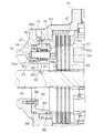
- the slack adjuster mechanism 57 is disposed further inside the pressing portion 70 and the mounting portion 72 of the piston 63. That is, as apparent from FIGS. 2 to 4, the space 43 for storing the brake device is divided into a space in which the brake disc plate 61 is disposed by the piston 63 and a space in which the slack adjuster mechanism 57 is disposed. There is. More specifically, the slack adjuster mechanism 57 is disposed in a space formed by the space enclosed by the mounting portion 72 and the sliding portion 73 of the piston 63 and the third storage portion 47.
- the slack adjuster mechanism 57 is a mechanism for maintaining the gap between the piston 63 and the brake disc plate 61 in a predetermined gap by mechanically adjusting the inoperative position of the piston 63. As shown in FIG. 4, the slack adjuster mechanism 57 includes a carrier 78, a rod 79, an adjusting portion 80, a return spring 81, and a stopper 82.
- the carrier 78 is formed in an annular shape, and includes a cylindrical support portion 84, a plurality of cases 85, and a fixing portion 86.
- the outer portion is in contact with and supported by the inner peripheral surface of the sliding portion 73 of the piston 63, and the inner portion is supported by the inner wall of the third storage portion 47.
- Annular grooves are formed on the outer peripheral surfaces of these, and seal members 88 and 89 are mounted respectively.
- the plurality of cases 85 are cylindrical and formed on the inner peripheral side of the support portion 84. Each case 85 is disposed corresponding to the position of the mounting portion 72 of the piston 63.
- three openings 85a, 85b and 85c are formed in line in the axial direction. More specifically, the first opening 85a is formed on the outermost side of the case 85, the second opening 85b is formed on the inner side, and the third opening 85c (opening) is formed on the inner side thereof. It is done.
- the inner diameter of the second opening 85b is larger than the diameter of the first opening 85a, and the inner diameter of the third opening 85c is larger than the inner diameter of the second opening 85b.
- the fixing portion 86 is formed so as to protrude inward from the inner end portion of the support portion 84.
- the fixing portion 86 is fixed to the side wall of the third storage portion 47 by a plurality of bolts 90.
- the rod 79 is disposed in the case 85 of the carrier 78 along the axial direction.
- the rod 79 has a rod main body 79a penetrating the three openings 85a, 85b, 85c, and a screw 79b (joint portion) formed at the outer end of the rod main body 79a.
- the outer diameter of the threaded portion 79b is smaller than the outer diameter of the rod body 79a.
- the screw portion 79 b is screwed into the screw hole 72 a of the mounting portion 72 of the piston 63.
- the rod 79 is axially moveable with the piston 63.
- the end surface of the rod main body 79 a on which the screw portion 79 b is formed is in contact with the end surface of the mounting portion 72 of the piston 63.
- the adjustment unit 80 is attached to the rod 79, and includes a washer 92 and a plurality of grip retaining rings 93 disposed in the third opening 85c.
- the washer 92 is axially movable relative to the rod 79. Further, the outer diameter of the washer 92 is larger than the inner diameter of the second opening 85 b. Therefore, the washer 92 abuts on the outer end surface which is the bottom surface of the third opening 85 c, and the movement to the axial direction outer side is restricted.
- the grip retaining ring 93 is engaged with the rod 79 with a predetermined frictional force. Then, when an axial force more than this frictional force acts on the grip retaining ring 93, the grip retaining ring 93 moves in the axial direction relatively to the rod 79.
- the return spring 81 is disposed at the second opening 85 b at the outer peripheral portion of the rod 79. One end of the return spring 81 is in contact with the end surface which is the bottom surface of the second opening 85 b, and the other end is in contact with the side surface of the washer 92. Note that, as shown in FIG. 4, when the piston 63 is not in operation, the return spring 81 biases the rod 79 and the piston 63 inward via the washer 92 and the grip retaining ring 93.
- the stopper 82 is formed in an annular shape, and the rod 79 penetrates the inner peripheral portion, and is disposed in the third opening 85 c.
- An annular groove is formed on the outer peripheral surface of the stopper 82, and is supported by the inner peripheral surface of the third opening 85c via an elastic member 94 disposed in the annular groove. Further, the inner side surface of the stopper 82 abuts on the side wall of the third opening 85 c, and the grip retaining ring 93 can abut on the outer side surface.
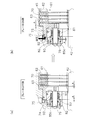
- FIGS. 5 (a) and 5 (b) show states in the initial state in which the brake disc plate 61 is not worn and in which the brake is off and the brake is on.
- the hydraulic oil is not supplied from the oil passage 75.
- the oil chamber 74 at the tip of the sliding portion 73 of the piston 63 is drained through the control valve.
- the piston 63 is moved by the return spring 81 to the inner inoperative position. More specifically, the biasing force of the return spring 81 is transmitted to the rod 79 via the washer 92 and the grip retaining ring 93. Accordingly, the rod 79 and the piston 63 connected to the tip of the rod 79 are moved inward by the biasing force of the return spring 81. For this reason, the pressing portion 70 of the piston 63 is separated from the brake disc plate 61, and the axle 42 can freely rotate.
- a gap A is formed between the rear surface of the pressing portion 70 of the piston 63 and the end surface of the first storage portion 45 in the axial direction.
- the rod 79, the grip ring 93, and the washer 92 move outward with the piston 63 against the biasing force of the return spring 81, and the washer 92 abuts on the axial end surface of the third opening 85c. Therefore, a similar gap A is formed between the grip retaining ring 93 and the stopper 82.
- Wear amount B The state of the adjustment operation at the time of brake off, on, and in the middle of operation when the brake disc plate 61 (mainly the friction material of the first disc plate 65) is worn by the wear amount B is shown in FIG.
- Fig.6 (a) The state at the time of a brake off is shown to Fig.6 (a). At the time of brake off, basically it is the same as FIG. 5A, but due to the wear of the brake disc plate 61, an initial stage between the pressing surface of the pressing portion 70 of the piston 63 and the first disc plate 65 A gap (A + B) is formed which is increased by the amount of wear B from the state.
- the brake hydraulic pressure exerts an axial force on the piston 63 that is sufficiently large as compared with the frictional force between the grip retaining ring 93 and the rod 79. Therefore, the frictional force of the grip retaining ring 93 against the rod 79 loses to the brake hydraulic pressure, and as shown in FIG. Move to the disc plate 65 side.
- the pressing portion 70 of the piston 63 presses the first disc plate 65, and the brake is turned on.
- a gap (A + B) of an initial gap A + a wear amount B is formed between the back surface of the pressing portion 70 of the piston 63 and the axial end surface of the first storage portion 45. Further, the gap between the grip retaining ring 93 and the stopper 82 remains the initial gap A.
- the stroke of the piston 63 can be maintained at the movement amount A in the initial state by the relative movement of the rod 79 and the grip retaining ring 93 by the amount of wear. Therefore, the amount of hydraulic fluid required for the brake on does not increase, and the time lag at the time of the brake on does not increase.
- the sliding portion 73 of the piston 63 is formed smaller in diameter than the outer diameter of the pressing portion 70, so that the structure becomes compact.
- backhoe loader has been described as an example of the work vehicle, the present invention is equally applicable to other work vehicles such as a wheel loader.
- the configuration of the adjustment unit is not limited to the above embodiment.
- other members may be used instead of the grip ring.
- the rod 79 is fixed to the inner peripheral portion 72 of the piston 63 with a screw, but the configuration for fixing is not limited to the screw.
- the slack adjuster mechanism can be disposed utilizing the axial space, it is compact.
Landscapes
- Engineering & Computer Science (AREA)
- General Engineering & Computer Science (AREA)
- Mechanical Engineering (AREA)
- Mining & Mineral Resources (AREA)
- Civil Engineering (AREA)
- Structural Engineering (AREA)
- Transportation (AREA)
- Braking Arrangements (AREA)
Description
図1に本発明の一実施形態によるバックホーローダ1の外観図を示している。バックホーローダ1は、1台で掘削作業及び積み込み作業を行うことができる作業車両である。このバックホーローダは主に、本体2と、ローダ3と、バックホー4と、左右のスタビライザ5と、を備えている。
このバックホーローダ1には、図2に示すように、後輪13を制動するためのブレーキ装置40が設けられている。ブレーキ装置40は、フレーム10の下部に支持されたアクスルハウジング41(図2参照)の内部に配置されている。
ブレーキ装置40は、後輪13側に配置されたブレーキユニット56と、ブレーキユニット56の車両内側に配置されたスラックアジャスタ機構57と、を有している。
図3に示すように、ブレーキユニット56は、複数のブレーキディスクプレート61と、バックアッププレート62と、ピストン63と、を有している。
スラックアジャスタ機構57は、ピストン63の押圧部70及び取付部72のさらに内側に配置されている。すなわち、図2~図4から明らかなように、ブレーキ装置収納用空間43は、ピストン63によってブレーキディスクプレート61が配置された空間と、スラックアジャスタ機構57が配置された空間と、に区分けされている。より詳細には、スラックアジャスタ機構57は、ピストン63の取付部72及び摺動部73によって囲まれる空間と第3収納部47とによって形成される空間に配置されている。
<初期状態>
ブレーキディスクプレート61が摩耗していない初期状態のブレーキオフ時及びブレーキオン時の状態を図5(a)(b)に示している。
ブレーキディスクプレート61(主に第1ディスクプレート65の摩擦材)が、摩耗量Bだけ摩耗した場合のブレーキオフ、オン時、及び作動途中における調整動作の様子を図6に示している。
(1)スラックアジャスタ機構57はピストン63の摺動部73の内周側に配置されているので、ブレーキ装置40の径方向寸法が大型化するのを避けることができる。また、スラックアジャスタ機構57は、アクスルハウジング41の内部における空きスペースを利用して配置されているので、ブレーキ装置40の軸方向寸法が長くなることはない。
本発明は以上のような実施形態に限定されるものではなく、本発明の範囲を逸脱することなく種々の変形又は修正が可能である。
40 ブレーキ装置
41 アクスルハウジング
42 アクスル
50 ファイナル減速機
56 ブレーキユニット
57 スラックアジャスタ機構
61 ブレーキディスクプレート
63 ピストン
70 押圧部
73 摺動部
78 キャリア
79 ロッド
79a ロッド本体
79b ねじ部
80 調整部
81 リターンスプリング
82 ストッパ
85 ケース
85a~85c 第1~第3開口部
92 ワッシャ
93 グリップ止め輪
Claims (12)
- 作業車両のアクスルハウジング内に設けられたブレーキ装置であって、
ブレーキディスクプレートと、前記アクスルハウジングに摺動自在に支持された摺動部及び前記ブレーキディスクプレートを押圧する押圧面が形成された押圧部を有するピストンと、を有するブレーキユニットと、
前記ピストンを挟んで前記ブレーキディスクプレートと軸方向において逆側のピストン背面側でかつ前記ピストンの摺動部より内周側に配置されるとともに、前記ピストンの押圧部側の端面より前記ピストン背面側に配置された部材で構成され、前記ピストンの非作動位置を機械的に調整することによって前記ピストンと前記ブレーキディスクプレートとの間の隙間を所定の隙間に維持するためのスラックアジャスタ機構と、
を備えた作業車両用ブレーキ装置。 - 前記ピストンの摺動部は、前記押圧部の押圧面とは逆側の側面から軸方向に突出して筒状に形成されている、
請求項1に記載の作業車両用ブレーキ装置。 - 前記スラックアジャスタ機構は、
前記ピストンの摺動部の内周側に配置され、複数のケースを有する筒状のキャリアと、 前記ケース内に軸方向に移動自在に配置されるとともに、先端部が前記ケースから突出して前記ピストンの内周部に連結され、先端面が前記ピストンの押圧部側の端面よりも前記ピストン背面側に位置するロッドと、
前記ケース内に配置され、前記ブレーキディスクプレートの摩耗量に応じて、前記ピストン非作動時における前記ロッドの前記ケースからの突出量を調整する調整部と、
を有する、請求項2に記載の作業車両用ブレーキ装置。 - 前記ケースは、前記ブレーキユニット側から軸方向に沿って順に、
前記ロッドが貫通する第1開口部と、
前記第1開口部より大径の第2開口部と、
前記調整部が配置され、前記第2開口部より大径の第3開口部と、
を有している、請求項3に記載の作業車両用ブレーキ装置。 - 前記スラックアジャスタ機構は、前記ピストンに対する作動力が解除された際に、前記ロッド及び前記ピストンを非作動位置に退避させるためのリターンスプリングをさらに有し、前記リターンスプリンは前記第2開口部に配置されている、請求項4に記載の作業車両用ブレーキ装置。
- 前記調整部は前記ロッドの外周面に所定の摩擦力で保持されて前記キャリアに対する前記ロッドの軸方向位置を規制する規制部材を有し、
前記規制部材は、前記ピストンが前記ブレーキディスクプレートに対して押圧された際に、前記ブレーキディスクプレートの摩耗量に応じて前記摩擦による保持力に抗して前記ロッドに対して軸方向に移動する、
請求項4又は5に記載の作業車両用ブレーキ装置。 - 前記規制部材は、前記第2開口部の内径よりも大きい径を有し、前記ピストンが前記ブレーキディスクプレートに対して押圧された際に、前記第3開口部の底面に当接可能である、請求項6に記載の作業車両用ブレーキ装置。
- 前記スラックアジャスタ機構は、前記第3開口部に配置され、前記ロッドに保持されている規制部材の移動を停止させるためのストッパをさらに有している、請求項4から7のいずれかに記載の作業車両用ブレーキ装置。
- 前記ロッドは、
前記第1開口部、前記第2開口部、及び前記第3開口部を貫通するロッド本体と、
前記ロッド本体の一端に形成され、前記ロッド本体の外径よりも小さい外径で、前記ピストンの内周部に形成された孔に挿入されて結合された結合部と、
を有し、
前記ロッド本体の前記結合部側の端面は前記ピストンの端面に当接している、
請求項4から8のいずれかに記載の作業車両用ブレーキ装置。 - 機器類を支持するフレームと、
フレームに搭載された運転室と、
前記運転室の前方又は後方に配置された作業機と、
複数の車輪と、
前記フレームに支持されたアクスルハウジングと、
前記アクスルハウジングの内部に配置され、前記車輪に連結されたアクスルと、
前記アクスルの回転を制動するための請求項1から9のいずれかに記載のブレーキ装置と、
を備えた作業車両。 - 前記アクスルと前記車輪との間に配置されたファイナル減速機をさらに備えた、請求項10に記載の作業車両。
- 前記ブレーキ装置は、前記ファイナル減速機の車両内側に配置されている、請求項11に記載の作業車両。
Priority Applications (4)
| Application Number | Priority Date | Filing Date | Title |
|---|---|---|---|
| GB1304493.8A GB2505540B (en) | 2012-01-17 | 2012-10-11 | Work vehicle and brake device thereof |
| JP2012550243A JP5211270B1 (ja) | 2012-01-17 | 2012-10-11 | 作業用車両及びそのブレーキ装置 |
| CN201280003434.6A CN103429927B (zh) | 2012-01-17 | 2012-10-11 | 作业用车辆及其制动装置 |
| US13/825,639 US8893860B2 (en) | 2012-01-17 | 2012-10-11 | Work vehicle and brake device thereof |
Applications Claiming Priority (2)
| Application Number | Priority Date | Filing Date | Title |
|---|---|---|---|
| JP2012-006870 | 2012-01-17 | ||
| JP2012006870 | 2012-01-17 |
Publications (1)
| Publication Number | Publication Date |
|---|---|
| WO2013108447A1 true WO2013108447A1 (ja) | 2013-07-25 |
Family
ID=48798884
Family Applications (1)
| Application Number | Title | Priority Date | Filing Date |
|---|---|---|---|
| PCT/JP2012/076300 Ceased WO2013108447A1 (ja) | 2012-01-17 | 2012-10-11 | 作業用車両及びそのブレーキ装置 |
Country Status (3)
| Country | Link |
|---|---|
| US (1) | US8893860B2 (ja) |
| CN (1) | CN103429927B (ja) |
| WO (1) | WO2013108447A1 (ja) |
Cited By (2)
| Publication number | Priority date | Publication date | Assignee | Title |
|---|---|---|---|---|
| CN106218605A (zh) * | 2016-08-25 | 2016-12-14 | 简式国际汽车设计(北京)有限公司 | 一种驻车制动器 |
| US9593729B2 (en) | 2015-04-27 | 2017-03-14 | Caterpillar Inc. | Brake assembly having slack adjustment mechanism |
Families Citing this family (2)
| Publication number | Priority date | Publication date | Assignee | Title |
|---|---|---|---|---|
| CN103758895B (zh) * | 2014-01-08 | 2015-10-28 | 索特传动设备有限公司 | 减速机制动器及工程机械 |
| FR3030001B1 (fr) * | 2014-12-12 | 2018-04-20 | Safran Landing Systems | Actionneur de freinage pour frein hydraulique de roue d`aeronef. |
Citations (6)
| Publication number | Priority date | Publication date | Assignee | Title |
|---|---|---|---|---|
| JPS5271694U (ja) * | 1975-11-26 | 1977-05-28 | ||
| JPS597927U (ja) * | 1982-07-07 | 1984-01-19 | 株式会社豊田自動織機製作所 | 車両用湿式デイスクブレ−キ |
| JPS63120921A (ja) * | 1986-11-11 | 1988-05-25 | Shinko Electric Co Ltd | 電磁クラツチ・ブレ−キにおける自動空隙調整装置 |
| JPH06109045A (ja) * | 1992-09-29 | 1994-04-19 | Central Japan Railway Co | 多板ディスクブレーキ装置 |
| JP2005029117A (ja) * | 2003-07-11 | 2005-02-03 | Tcm Corp | 車両用駆動装置 |
| JP2011196480A (ja) * | 2010-03-19 | 2011-10-06 | Komatsu Ltd | 駆動装置 |
Family Cites Families (5)
| Publication number | Priority date | Publication date | Assignee | Title |
|---|---|---|---|---|
| US4146116A (en) * | 1977-09-15 | 1979-03-27 | Rockwell International Corporation | Friction brake |
| JP2001193773A (ja) | 2000-01-12 | 2001-07-17 | Komatsu Forklift Co Ltd | 戻り位置調整装置 |
| CN100453842C (zh) * | 2007-07-13 | 2009-01-21 | 三一重工股份有限公司 | 制动力可调的盘式液压制动器 |
| JP5039530B2 (ja) * | 2007-12-20 | 2012-10-03 | 三菱重工業株式会社 | 車両用湿式多板ブレーキ装置 |
| CN201241925Y (zh) * | 2008-08-19 | 2009-05-20 | 一拖(洛阳)开创装备科技有限公司 | 驱动桥用液压湿式多片制动器 |
-
2012
- 2012-10-11 US US13/825,639 patent/US8893860B2/en not_active Expired - Fee Related
- 2012-10-11 WO PCT/JP2012/076300 patent/WO2013108447A1/ja not_active Ceased
- 2012-10-11 CN CN201280003434.6A patent/CN103429927B/zh not_active Expired - Fee Related
Patent Citations (6)
| Publication number | Priority date | Publication date | Assignee | Title |
|---|---|---|---|---|
| JPS5271694U (ja) * | 1975-11-26 | 1977-05-28 | ||
| JPS597927U (ja) * | 1982-07-07 | 1984-01-19 | 株式会社豊田自動織機製作所 | 車両用湿式デイスクブレ−キ |
| JPS63120921A (ja) * | 1986-11-11 | 1988-05-25 | Shinko Electric Co Ltd | 電磁クラツチ・ブレ−キにおける自動空隙調整装置 |
| JPH06109045A (ja) * | 1992-09-29 | 1994-04-19 | Central Japan Railway Co | 多板ディスクブレーキ装置 |
| JP2005029117A (ja) * | 2003-07-11 | 2005-02-03 | Tcm Corp | 車両用駆動装置 |
| JP2011196480A (ja) * | 2010-03-19 | 2011-10-06 | Komatsu Ltd | 駆動装置 |
Cited By (2)
| Publication number | Priority date | Publication date | Assignee | Title |
|---|---|---|---|---|
| US9593729B2 (en) | 2015-04-27 | 2017-03-14 | Caterpillar Inc. | Brake assembly having slack adjustment mechanism |
| CN106218605A (zh) * | 2016-08-25 | 2016-12-14 | 简式国际汽车设计(北京)有限公司 | 一种驻车制动器 |
Also Published As
| Publication number | Publication date |
|---|---|
| US20140112747A1 (en) | 2014-04-24 |
| CN103429927A (zh) | 2013-12-04 |
| US8893860B2 (en) | 2014-11-25 |
| CN103429927B (zh) | 2016-03-30 |
Similar Documents
| Publication | Publication Date | Title |
|---|---|---|
| JP5654129B2 (ja) | ユニットブレーキ | |
| CN114585835B (zh) | 变速器组件 | |
| CA1223220A (en) | Fail-safe spring-loaded hydraulic brake and control system therefor | |
| WO2010123100A1 (ja) | ディスクブレーキ装置 | |
| JP2010038307A (ja) | ディスクブレーキ | |
| WO2009081613A1 (ja) | 車両用湿式多板ブレーキ装置 | |
| JP2016169771A (ja) | ブレーキ装置 | |
| US8893860B2 (en) | Work vehicle and brake device thereof | |
| CN113775678B (zh) | 电子钳式制动器及其操作方法 | |
| WO2012169018A1 (ja) | ディスクブレーキ装置及びキャリパスライド機構 | |
| WO2012118133A1 (ja) | ウェッジカム式ブレーキの自動隙間調整機構 | |
| JP5211270B1 (ja) | 作業用車両及びそのブレーキ装置 | |
| JP2015077830A (ja) | アクスル装置 | |
| JP2019090485A (ja) | 作業車輌 | |
| JP4162559B2 (ja) | 作業車の作業用伝動構造 | |
| CN211521434U (zh) | 一种用于清障车的行星绞盘 | |
| JP2015135004A (ja) | ホイール式建設機械 | |
| CN101983295B (zh) | 用于作业机械的制动器、轮毂单元及作业机械 | |
| US20250269828A1 (en) | Axle Assembly | |
| JP6371784B2 (ja) | ホイール式建設機械 | |
| JP2009079740A (ja) | 作業機のブレーキ構造 | |
| JP2011208788A (ja) | 作業車の旋回伝動装置 | |
| WO2025079528A1 (ja) | 電動制動装置 | |
| KR20240030803A (ko) | 건설기계용 액슬 브레이크 유격 자동조절장치 | |
| JP2018016115A (ja) | 車両用ブレーキ |
Legal Events
| Date | Code | Title | Description |
|---|---|---|---|
| WWE | Wipo information: entry into national phase |
Ref document number: 201280003434.6 Country of ref document: CN |
|
| ENP | Entry into the national phase |
Ref document number: 2012550243 Country of ref document: JP Kind code of ref document: A |
|
| ENP | Entry into the national phase |
Ref document number: 1304493 Country of ref document: GB Kind code of ref document: A Free format text: PCT FILING DATE = 20121011 |
|
| WWE | Wipo information: entry into national phase |
Ref document number: 1304493.8 Country of ref document: GB |
|
| WWE | Wipo information: entry into national phase |
Ref document number: 13825639 Country of ref document: US |
|
| 121 | Ep: the epo has been informed by wipo that ep was designated in this application |
Ref document number: 12866261 Country of ref document: EP Kind code of ref document: A1 |
|
| 122 | Ep: pct application non-entry in european phase |
Ref document number: 12866261 Country of ref document: EP Kind code of ref document: A1 |
|
| NENP | Non-entry into the national phase |
Ref country code: DE |