WO2013094555A1 - 露光装置および露光マスク - Google Patents
露光装置および露光マスク Download PDFInfo
- Publication number
- WO2013094555A1 WO2013094555A1 PCT/JP2012/082641 JP2012082641W WO2013094555A1 WO 2013094555 A1 WO2013094555 A1 WO 2013094555A1 JP 2012082641 W JP2012082641 W JP 2012082641W WO 2013094555 A1 WO2013094555 A1 WO 2013094555A1
- Authority
- WO
- WIPO (PCT)
- Prior art keywords
- exposure
- substrate
- pattern
- mask
- irradiation region
- Prior art date
- Legal status (The legal status is an assumption and is not a legal conclusion. Google has not performed a legal analysis and makes no representation as to the accuracy of the status listed.)
- Ceased
Links
Images









Classifications
-
- G—PHYSICS
- G03—PHOTOGRAPHY; CINEMATOGRAPHY; ANALOGOUS TECHNIQUES USING WAVES OTHER THAN OPTICAL WAVES; ELECTROGRAPHY; HOLOGRAPHY
- G03F—PHOTOMECHANICAL PRODUCTION OF TEXTURED OR PATTERNED SURFACES, e.g. FOR PRINTING, FOR PROCESSING OF SEMICONDUCTOR DEVICES; MATERIALS THEREFOR; ORIGINALS THEREFOR; APPARATUS SPECIALLY ADAPTED THEREFOR
- G03F7/00—Photomechanical, e.g. photolithographic, production of textured or patterned surfaces, e.g. printing surfaces; Materials therefor, e.g. comprising photoresists; Apparatus specially adapted therefor
- G03F7/70—Microphotolithographic exposure; Apparatus therefor
- G03F7/70216—Mask projection systems
- G03F7/70283—Mask effects on the imaging process
Definitions
- the present invention relates to an exposure apparatus and an exposure mask, and more particularly to an exposure apparatus that transfers a pattern drawn on the exposure mask to a substrate, and an exposure mask that is preferably used in the exposure apparatus.
- Patent Document 1 since a plurality of drawing patterns are formed on one mask, one mask can be used for a plurality of exposure processes, The number of masks is reduced. However, since a plurality of drawing patterns are two-dimensionally formed on one mask, it may take time to switch the drawing patterns. Therefore, it is difficult to switch the drawing pattern without stopping the movement of the substrate to be exposed, and there is a problem that the production efficiency cannot be improved.
- the present invention has been made in view of the above-mentioned problems, and its main purpose is to provide an exposure apparatus that can shorten the exposure mask switching time. Another object of the present invention is to provide an exposure mask suitably used for the exposure apparatus.
- An exposure apparatus includes a flat plate-shaped substrate, a stage on which the substrate is mounted, the substrate being moved in the surface direction of the substrate, a light source that generates exposure light irradiated on the substrate, and exposure that transmits the exposure light.
- a plurality of patterns are formed, and an exposure mask that irradiates the substrate with exposure light through the exposure pattern, and a mask drive unit that moves the exposure mask in parallel with the substrate are provided.
- the substrate has a first irradiation region and a second irradiation region provided on the rear side in the direction in which the substrate moves during exposure with respect to the first irradiation region.
- the exposure pattern includes a first pattern and a second pattern different from the first pattern.
- the first irradiation area is exposed through the first pattern while moving the substrate by the stage, and after the exposure of the first irradiation area is completed, the exposure mask is moved while continuing the movement of the substrate, and the first pattern is moved from the first pattern. Switching to the two patterns is performed, and the second irradiation region is exposed through the second pattern while continuing the movement of the substrate.
- the surface direction of the substrate refers to a direction in which the front surface and the back surface of the flat substrate extend and is orthogonal to the thickness direction of the substrate.
- exposure of the second irradiation area may be started during switching from the first pattern to the second pattern. Or in the said exposure apparatus, you may start exposure of a 2nd irradiation area
- the exposure mask according to the present invention is an exposure mask used in the exposure apparatus according to any one of the above aspects, and a plurality of exposure patterns are arranged in the moving direction of the exposure mask.
- the second pattern may be provided on the rear side in the movement direction during the exposure process of the substrate with respect to the first pattern.
- the exposure pattern is formed so as to extend in a direction orthogonal to the moving direction of the exposure mask, and a shielding region that shields the exposure light is exposed between the first pattern and the second pattern. You may form so that it may extend in the direction orthogonal to the moving direction of a mask.
- the exposure mask switching time can be shortened and the production efficiency can be improved.
- FIG. 6 is a first schematic diagram illustrating a state of exposure pattern switching according to the first embodiment.
- FIG. 10 is a second schematic diagram showing the exposure pattern switching state of the first embodiment.
- FIG. 10 is a third schematic diagram illustrating an exposure pattern switching state according to the first embodiment.
- FIG. 10 is a fourth schematic diagram illustrating an exposure pattern switching state in the first embodiment.
- FIG. 10 is a fifth schematic diagram illustrating an exposure pattern switching state in the first embodiment.
- FIG. 10 is a sixth schematic diagram illustrating an exposure pattern switching state according to the first embodiment.
- FIG. 10 is a first schematic diagram illustrating an exposure pattern switching state according to the second embodiment.
- FIG. 10 is a second schematic diagram showing an exposure pattern switching state in the second embodiment.
- FIG. 10 is a third schematic diagram illustrating an exposure pattern switching state according to the second embodiment.
- FIG. 10 is a fourth schematic diagram showing an exposure pattern switching state in the second embodiment.
- FIG. 10 is a fifth schematic diagram illustrating an exposure pattern switching state according to the second embodiment.
- FIG. 10 is a sixth schematic diagram illustrating an exposure pattern switching state according to the second embodiment.
- FIG. 10 is a first schematic diagram illustrating an exposure pattern switching state according to the third embodiment.
- FIG. 10 is a second schematic diagram showing an exposure pattern switching state in the third embodiment.
- FIG. 10 is a first schematic diagram illustrating an exposure pattern switching state according to the third embodiment.
- FIG. 10 is a second schematic diagram showing an exposure pattern switching state in the third embodiment.
- FIG. 10 is a third schematic diagram illustrating an exposure pattern switching state according to the third embodiment.
- FIG. 10 is a fourth schematic diagram illustrating an exposure pattern switching state according to the third embodiment.
- FIG. 10 is a fifth schematic diagram illustrating an exposure pattern switching state according to the third embodiment.
- FIG. 1 is a schematic diagram showing an outline of the configuration of the exposure apparatus 1.
- the exposure apparatus 1 is used as an apparatus for irradiating the photo-alignment film material with ultraviolet rays, for example.
- the exposure apparatus 1 includes a stage 20 on which a flat substrate 10 is mounted, a light source 30 that generates exposure light L irradiated on the substrate 10, and a predetermined pattern transferred to the substrate 10.
- a formed exposure mask 40 and a mask driving unit 50 for holding the exposure mask 40 are provided.
- the exposure apparatus 1 irradiates the substrate 10 placed on the stage 20 with the exposure light L generated by the light source 30 through the exposure mask 40.
- the exposure apparatus 1 transfers a predetermined pattern to the first and second irradiation areas 16 and 18 provided on the surface of the substrate 10.
- the mask drive unit 50 includes a main body 51, a drive shaft 52, and a mask holding unit 53.
- the driving force generated in the main body 51 is transmitted to the mask holder 53 via the drive shaft 52, and the mask holder 53 reciprocates in the left-right direction in the figure.
- the exposure mask 40 held on the lower surface of the mask holder 53 reciprocates in the movement direction DR2.
- the movement direction DR2 of the exposure mask 40 is parallel to the movement direction DR1 of the substrate 10.
- the substrate 10 is mounted on the stage 20, and the exposure mask 40 is disposed above the substrate 10 so as to face the substrate 10.
- the exposure apparatus 1 has a mask holding unit 53, and the exposure mask 40 used for the exposure processing of the substrate 10 is attached to the mask holding unit 53.
- the exposure light L may be, for example, ultraviolet light.
- the light source 30 is an ultraviolet light source that generates ultraviolet light.
- the exposure light L may be irradiated perpendicularly to the surface of the substrate 10 or may be irradiated obliquely with respect to the surface of the substrate 10.
- the exposure apparatus 1 also includes a control unit 80.
- the control unit 80 transmits a control signal C ⁇ b> 1 to the light source 30 to control irradiation or stop of the exposure light L from the light source 30.
- the control unit 80 transmits a control signal C2 to the mask driving unit 50, and controls the movement of the exposure mask 40 along the movement direction DR2.
- the controller 80 transmits a control signal C3 to the stage 20 and controls the movement of the substrate 10 along the movement direction DR1.
- FIG. 2 is a schematic diagram showing the relationship between the substrate 10 exposed in the exposure apparatus 1 and the exposure mask 40.
- FIG. 2 shows a single substrate 10 in plan view, and shows an arrangement of a mask group composed of a plurality of exposure masks 40 with respect to the substrate 10.
- the exposure mask 40 is small with respect to the substrate 10, and the exposure processing of the entire substrate 10 is performed by arranging a plurality of exposure masks 40 side by side.
- it is not limited to the mask group containing the some exposure mask 40, The structure which can implement the exposure process of the board
- Each exposure mask 40 is held by a mask holding portion 53 whose side shape is shown in FIG.
- the mask holding part 53 has a frame shape that engages with the peripheral part of the exposure mask 40 so as not to obstruct the optical path of the exposure light L that is irradiated from the light source 30 to the substrate 10 via the exposure mask 40. Is provided.
- the moving direction DR2 of the exposure mask 40 is indicated by a double arrow shown in FIG. This double arrow also indicates the direction of relative movement of the exposure mask 40 with respect to the substrate 10.
- the substrate 10 and the exposure mask 40 are double-headed. Move in the direction of.
- the plurality of exposure masks 40 are arranged in two rows in a direction orthogonal to the direction of relative movement between the substrate 10 and the exposure mask 40.
- the plurality of exposure masks 40 are arranged so that the entire surface of the substrate 10 can be exposed.
- Two masks adjacent in a direction orthogonal to the relative movement direction of the substrate 10 and the exposure mask 40 are arranged in different rows.
- the irradiation areas of the exposure light L irradiated onto the substrate 10 via these two exposure masks 40 may be adjacent to each other without any gap, or the irradiation areas may partially overlap.
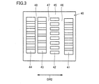
- FIG. 3 is a schematic diagram showing a schematic configuration of an exposure mask 40 used for the exposure processing of the substrate 10.
- a plurality of exposure patterns 41, 42, 43, 44 are drawn on one exposure mask 40.
- the exposure patterns 41, 42, 43, and 44 have a property of transmitting the exposure light L.
- one of the exposure patterns suitable for the exposure processing of the substrate 10 to be processed is selected, and the exposure light L is transmitted through the selected exposure pattern.
- the number of exposure patterns drawn on one exposure mask 40 is not limited and may be an arbitrary number.
- the exposure pattern 41 is for a 45-type TFT (Thin Film Transistor) substrate and the exposure pattern 42 is for a 45-type CF (Color Filter) substrate.
- the exposure pattern 43 can be formed as a pattern for a 75-type TFT substrate, and the exposure pattern 44 can be formed as a pattern for a 75-type CF substrate. That is, different drawing patterns are formed in the plurality of exposure patterns 41, 42, 43, 44. The same drawing pattern may be formed in a part of the plurality of exposure patterns 41, 42, 43, 44.
- the four exposure patterns 41, 42, 43, 44 are surrounded by the edge 45 of the exposure mask 40.
- Shielding regions 46, 47, 48 are interposed between the respective exposure patterns 41, 42, 43, 44 adjacent to the movement direction DR2 of the exposure mask 40.
- the shielding regions 46, 47, and 48 are made of a material that does not transmit the exposure light L, such as chromium, and shields the exposure light L.
- the shielding area 46 is interposed between the exposure patterns 41 and 42 and separates the exposure pattern 41 and the exposure pattern 42 from each other.
- the shielding area 47 is interposed between the exposure patterns 42 and 43 and separates the exposure pattern 42 and the exposure pattern 43 from each other.
- the shielding area 47 is interposed between the exposure patterns 43 and 44 and separates the exposure pattern 43 and the exposure pattern 44 from each other.
- the plurality of exposure patterns 41, 42, 43, and 44 are arranged only in the movement direction DR2 of the exposure mask 40 indicated by a double-headed arrow in FIG. 3, and are not arranged in a direction that intersects the movement direction DR2.
- the exposure mask 40 When the exposure mask 40 is moved to switch the exposure patterns 41, 42, 43, and 44, the exposure mask 40 only needs to be translated in the movement direction DR2.
- Each of the plurality of exposure patterns 41, 42, 43, 44 is formed in a straight line extending in the vertical direction in the figure orthogonal to the moving direction DR 2 of the exposure mask 40.
- the shielding regions 46, 47, 48 that separate the exposure patterns 41, 42, 43, 44 are also formed in a straight line extending in the vertical direction in the figure orthogonal to the moving direction DR2 of the exposure mask 40.
- the drawing pattern drawn on each of the exposure patterns 41, 42, 43, and 44 is preferably a linear pattern parallel to the moving direction DR2 of the exposure mask 40 as shown in FIG.
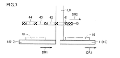
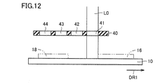
- FIGS. 4 to 9 are schematic diagrams showing the switching status of the exposure patterns 41 and 42 of the first embodiment.
- the substrate 10 and the exposure mask 40 are shown in the configuration of the exposure apparatus 1 shown in FIG. 1, but the stage 20 for moving the substrate 10 and the exposure mask 40 are moved for simplicity.
- the mask driving unit 50, the light source 30, and the like are not shown.
- the switching operation of the exposure patterns 41 and 42 using the exposure apparatus 1 having the above-described configuration for optimally exposing the irradiation regions 16 and 18 on which different patterns on the surface of the substrate 10 are to be exposed will be described with reference to FIGS. This will be described with reference to FIG.
- the substrate 10 includes different substrates 11 and 12, the substrate 11 is provided with the first irradiation region 16, and the substrate 12 is provided with the second irradiation region 18.
- the substrate 11 is a substrate disposed on the front side in the movement direction DR1 of the substrate 10
- the substrate 12 is a substrate disposed on the rear side in the movement direction DR1 of the substrate 10.
- the second irradiation region 18 is provided behind the first irradiation region 16 in the movement direction DR1 in which the substrates 11 and 12 move during exposure.
- the exposure mask 40 includes an exposure pattern 41 as a first pattern and an exposure pattern 42 as a second pattern different from the first pattern.
- the exposure pattern 42 is provided behind the exposure pattern 41 in the movement direction DR1 of the substrates 11 and 12 during the exposure process.
- the exposure patterns 41 and 42 to be used are formed at any position of the exposure mask 40. To figure out.
- the exposure mask 40 is moved so that the set position of the exposure pattern 42 acquired in advance and the position of the actual exposure pattern 42 are aligned with each other. Position accuracy has been improved.
- the exposure light L is irradiated via the exposure pattern 41 to the first irradiation region 16 provided on the surface of the substrate 11 while moving the substrates 11 and 12 in the movement direction DR1 by the stage 20. Yes.
- the exposure mask 40 is stopped.
- the substrate 11 is irradiated with the exposure light L via the exposure mask 40 while relatively moving the exposure mask 40 and the substrate 11 with the moving speed of the substrate 11 as a relative speed.
- one exposure pattern 41 formed on the exposure mask 40 is transferred to the first irradiation region 16 of the substrate 11, and the substrate 11 is subjected to scanning exposure.
- the exposure light L is exposed to the entire first irradiation region 16 and the state shown in FIG. 5 is obtained.
- the exposure processing of the first irradiation region 16 is completed.
- the exposure light L has reached the rear end of the first irradiation region 16. It is determined that 16 exposures have been completed.
- the light source 30 may stop the irradiation of the exposure light L.
- the exposure possible region L0 in which the light generated by the light source 30 can be irradiated to the substrate 10 via the exposure pattern 41 is completely removed from the first irradiation region 16 as shown in FIG. Become.
- the light source 30 may stop the irradiation of the exposure light L at this timing.
- switching from the exposure pattern 41 to the exposure pattern 42 is started.
- the exposure mask 40 moves in the movement direction DR2, which is the same direction as the movement direction DR1 of the substrate 10.
- the substrate 10 continues to move without being stopped.
- the exposure mask 40 completes switching from the exposure pattern 41 to the exposure pattern 42 before the exposure possible region L0 overlaps the second irradiation region 18.
- the exposure patterns 41 and 42 have already been switched, and the exposure processing of the second irradiation region 18 is possible. Therefore, there is no need to stop the substrate 12 and wait for switching of the exposure patterns 41 and 42. Therefore, the production efficiency is improved.
- the exposure mask 40 In order to switch the exposure patterns 41 and 42, the exposure mask 40 is moved in the movement direction DR2 toward a predetermined coordinate, and the movement of the substrates 11 and 12 is continued. Due to this movement, the exposure possible region L0 shown in FIG. 7 changes from the state in the middle of the transition from the exposure pattern 41 to the exposure pattern 42, and the exposure possible region L0 shown in FIG. To do. When the exposure possible region L0 overlaps the exposure pattern 42, the exposure mask 40 stops.
- the exposure possible region L0 is in a state shown in FIG. 9 overlapping the second irradiation region 18.
- the light source 30 resumes the irradiation of the exposure light L while continuing the movement of the substrate 12, whereby the exposure processing of the second irradiation region 18 is started.
- the exposure process for the second irradiation region 18 is started after the switching from the exposure pattern 41 to the exposure pattern 42 is completed.
- the exposure possible region L0 has not yet reached the second irradiation region 18.
- the switching of the exposure patterns 41 and 42 is completed faster than the substrate 12 is moved to a state where the exposure process of the second irradiation region 18 is possible. Therefore, it is not necessary to separately secure time for switching the exposure patterns 41 and 42, and the time required for the exposure process can be shortened, so that the production efficiency can be improved.
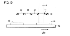
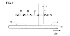
- FIGS. 10 to 15 are schematic diagrams showing the switching state of the exposure patterns 41 and 42 according to the second embodiment.
- the first irradiation region 16 is provided on the substrate 11 and the second irradiation region 18 is provided on another substrate 12 different from the substrate 11.
- a single irradiation region 16 is provided.
- the substrate 10 is provided with both the first irradiation region 16 and the second irradiation region 18.
- the second embodiment is an example corresponding to the case where the substrate 10 is a glass substrate for a liquid crystal panel, for example, and a plurality of different types of liquid crystal panels are formed from a single glass substrate.
- FIGS. 10 to 14 are diagrams corresponding to FIGS. 4 to 7 and 9 described in the first embodiment.
- the exposure patterns 41 and 42 are switched during the movement of the substrate 10 as in the first embodiment. Switching of the exposure patterns 41 and 42 is completed within the time from the exposure possible region L0 passing through the first irradiation region 16 to overlapping the second irradiation region 18, and exposure is performed as in the first embodiment. Processing time has been reduced.
- FIG. 15 shows the movement of the exposure mask 40 for returning the exposure pattern after the exposure processing of the second irradiation region 18 is completed.
- the exposure mask 40 moves in the moving direction DR2 shown in FIG. As a result, the exposure possible region L0 returns from the exposure pattern 42 to the exposure pattern 41, and the next substrate is prepared for exposure processing.
- FIGS. 3 are schematic diagrams showing the switching status of the exposure patterns 41 and 42 according to the third embodiment.
- the exposure mask 40 is switched after the exposure processing of the first irradiation region 16 is completed, and the exposure processing of the second irradiation region 18 is started after the switching from the exposure pattern 41 to the exposure pattern 42 is completed. It was.
- the exposure process of the second irradiation region 18 is started with the substrate 10 and the exposure mask 40 both moved. That is, in the third embodiment, the exposure of the second irradiation region 18 is started during the switching from the exposure pattern 41 to the exposure pattern 42.
- both the first irradiation region 16 and the second irradiation region 18 are provided on a single substrate 10.
- the exposure light L is irradiated through the exposure pattern 41 to the irradiation region 16 on the surface of the substrate 11 while moving the substrate 10 in the movement direction DR1.
- the exposure mask 40 is stopped. Thereby, one exposure pattern 41 formed on the exposure mask 40 is transferred to the first irradiation region 16 of the substrate 10, and the substrate 10 is subjected to scanning exposure.
- the exposure light L is exposed to the entire first irradiation region 16, and the state shown in FIG. 17 is obtained.
- the exposure processing of the first irradiation region 16 is completed.
- the movement of the exposure mask 40 in the movement direction DR2 is started while continuing the movement of the substrate 10, and switching from the exposure pattern 41 to the exposure pattern 42 is started.
- the exposure mask 40 By moving the exposure mask 40 in the movement direction DR2 for switching between the exposure patterns 41 and 42 and continuing the movement of the substrate 10, the exposure light L shown in FIG. Both are transmitted and the substrate 10 is irradiated.
- the exposure process of the second irradiation region 18 is started by irradiating the second irradiation region 18 with the exposure light L via the exposure pattern 42. At this time, the exposure process to the second irradiation region 18 of the substrate 10 is performed while moving the exposure mask 40.
- the exposure mask 40 When the exposure mask 40 reaches a position where all of the exposure light L generated by the light source 30 is irradiated onto the substrate 10 via the exposure pattern 42, the exposure mask 40 stops. Thereafter, the substrate 10 further continues to move, whereby the scanning exposure of the second irradiation region 18 is continued, and the state shown in FIG. 19 is obtained. From the state shown in FIG. 19, the movement of the substrate 10 is continued, and the scanning exposure of the second irradiation region 18 is performed.
- FIG. 20 shows the movement of the exposure mask 40 for returning the exposure pattern after the exposure processing of the second irradiation region 18 is completed.
- the exposure mask 40 moves in the movement direction DR2 shown in FIG. As a result, the exposure possible region L0 returns from the exposure pattern 42 to the exposure pattern 41, and the next substrate is prepared for exposure processing.
- the exposure apparatus of the third embodiment after the exposure of the first irradiation region 16 is completed, the second irradiation that is performed during the switching of the exposure patterns 41 and 42 without waiting for the completion of the switching of the exposure patterns 41 and 42. Exposure of area 18 is started. Therefore, the time required for the exposure process can be further shortened, and the production efficiency can be further improved.
- the interval between the first irradiation region 16 and the second irradiation region 18 can be reduced.
- substrates 10 can be reduced, and the utilization efficiency of the board
Landscapes
- Physics & Mathematics (AREA)
- General Physics & Mathematics (AREA)
- Preparing Plates And Mask In Photomechanical Process (AREA)
- Exposure And Positioning Against Photoresist Photosensitive Materials (AREA)
- Exposure Of Semiconductors, Excluding Electron Or Ion Beam Exposure (AREA)
Abstract
露光マスクの切り替え時間を短縮できる露光装置を提供する。露光装置(1)は、基板(10)と、露光光(L)を透過する露光パターン(41~44)が複数形成され、露光パターン(41~44)を介して基板(10)に露光光(L)を照射する露光マスク(40)とを備える。基板(10)は、第一の照射領域(16)と、第一の照射領域(16)に対し露光時に基板(10)が移動する移動方向(DR1)の後方側に設けられた第二の照射領域(18)とを有する。基板(10)を移動しながら露光パターン(41)を介して第一の照射領域(16)を露光し、第一の照射領域(16)の露光終了後、基板(10)の移動を継続しながら露光マスク(40)を移動して露光パターン(41)から露光パターン(42)への切り替えを行ない、基板(10)の移動を継続しながら露光パターン(42)を介して第二の照射領域(18)を露光する。
Description
本発明は、露光装置および露光マスクに関し、特に、露光マスクに描画されたパターンを基板に転写する露光装置、および、その露光装置に好適に用いられる露光マスクに関する。
露光マスク装置に関し、従来、各製造工程の各露光工程に必要な複数個の描画パターンを同一のマスクに搭載し、各露光工程で必要な描画パターンを選択し、かつその他のブロックのパターンは遮光して露光する装置が提案されている(たとえば、特開2003-21892号公報(特許文献1)参照)。
特開2003-21892号公報(特許文献1)に記載の装置では、複数個の描画パターンが一枚のマスクに形成されていることから、一枚のマスクを複数の露光工程に使用可能とし、マスクの枚数を低減している。しかし、一枚のマスクに二次元的に複数の描画パターンが形成されているため、描画パターンの切り替えに時間を要する場合がある。そのため、露光される対象の基板の移動を止めることなく描画パターンを切り替えることが困難であり、生産効率を向上できない問題があった。
本発明は上記の課題に鑑みてなされたものであり、その主たる目的は、露光マスクの切り替え時間を短縮できる、露光装置を提供することである。また、本発明の他の目的は、その露光装置に好適に用いられる露光マスクを提供することである。
本発明に係る露光装置は、平板形状の基板と、基板を搭載し、基板を基板の面方向に移動させるステージと、基板に照射される露光光を発生する光源と、露光光を透過する露光パターンが複数形成され、露光パターンを介して基板に露光光を照射する露光マスクと、露光マスクを基板に並行に移動させるマスク駆動部と、を備える。基板は、第一の照射領域と、第一の照射領域に対し露光時に基板が移動する方向の後方側に設けられた第二の照射領域とを有する。露光パターンは、第一パターンと、第一パターンと異なる第二パターンとを含む。ステージにより基板を移動しながら第一パターンを介して第一の照射領域を露光し、第一の照射領域の露光終了後、基板の移動を継続しながら露光マスクを移動して第一パターンから第二パターンへの切り替えを行ない、基板の移動を継続しながら第二パターンを介して第二の照射領域を露光する。ここで、基板の面方向とは、平板形状の基板の表面および裏面の延びる方向であって、基板の厚さ方向に直交する方向をいう。
上記露光装置において、第一パターンから第二パターンへの切り替え中に第二の照射領域の露光を開始してもよい。または、上記露光装置において、第一パターンから第二パターンへの切り替え終了後に第二の照射領域の露光を開始してもよい。
本発明に係る露光マスクは、上記のいずれかの局面の露光装置に用いられる露光マスクであって、露光パターンは、露光マスクの移動方向に複数並べられている。
上記露光マスクにおいて、第二パターンは、第一パターンに対し、基板の露光処理中の移動方向の後方側に設けられていてもよい。
上記露光マスクにおいて、露光パターンは、露光マスクの移動方向に直交する方向に延びるように形成されており、第一パターンと第二パターンとの間には、露光光を遮蔽する遮蔽領域が、露光マスクの移動方向に直交する方向に延びるように形成されていてもよい。
本発明の露光装置によると、露光マスクの切り替え時間を短縮でき、生産効率を向上することができる。
以下、図面に基づいてこの発明の実施の形態を説明する。なお、以下の図面において、同一または相当する部分には同一の参照番号を付し、その説明は繰返さない。
(実施の形態1)
図1は、露光装置1の構成の概略を示す模式図である。露光装置1は、たとえば、光配向膜材料に紫外線を照射するための装置として用いられる。図1に示すように、露光装置1は、平板形状の基板10を搭載するステージ20と、基板10に照射される露光光Lを発生する光源30と、基板10に転写される所定のパターンが形成された露光マスク40と、露光マスク40を保持するマスク駆動部50とを備える。露光装置1は、ステージ20上に載置された基板10に露光マスク40を介して、光源30で発生する露光光Lを照射する。これにより露光装置1は、基板10の表面に設けられた第一および第二の照射領域16,18に所定のパターンを転写する。
図1は、露光装置1の構成の概略を示す模式図である。露光装置1は、たとえば、光配向膜材料に紫外線を照射するための装置として用いられる。図1に示すように、露光装置1は、平板形状の基板10を搭載するステージ20と、基板10に照射される露光光Lを発生する光源30と、基板10に転写される所定のパターンが形成された露光マスク40と、露光マスク40を保持するマスク駆動部50とを備える。露光装置1は、ステージ20上に載置された基板10に露光マスク40を介して、光源30で発生する露光光Lを照射する。これにより露光装置1は、基板10の表面に設けられた第一および第二の照射領域16,18に所定のパターンを転写する。
図1に示す右向きの矢印は、ステージ20の移動方向、すなわち、ステージ20上に載置された基板10の移動方向DR1を示す。ステージ20は、基板10の面方向に延びる一直線に沿う方向に、基板10を移動させる。図1に示す左右方向の両矢印は、露光マスク40の移動方向DR2を示す。マスク駆動部50は、本体部51と、駆動軸52と、マスク保持部53とを含む。本体部51において発生した駆動力が、駆動軸52を介してマスク保持部53に伝達され、マスク保持部53は図中左右方向に往復移動する。マスク保持部53の移動に伴い、マスク保持部53の下面に保持された露光マスク40は、移動方向DR2に往復移動する。露光マスク40の移動方向DR2は、基板10の移動方向DR1に対し平行である。
基板10はステージ20に搭載され、露光マスク40は基板10の上方に基板10に対向して配置されている。露光装置1はマスク保持部53を有し、基板10の露光処理のために用いられる露光マスク40は、マスク保持部53に取り付けられている。光源30から露光マスク40を介して基板10に露光光Lを照射することにより、基板10の露光処理が行なわれる。露光光Lは、たとえば紫外光であってもよく、その場合、光源30は紫外光を発生する紫外光源である。露光光Lは、基板10の表面に対し垂直に照射されてもよく、または基板10の表面に対し傾斜して照射されてもよい。
露光装置1はまた、制御部80を備える。制御部80は、光源30に対し制御信号C1を伝送し、光源30からの露光光Lの照射または停止を制御する。制御部80は、マスク駆動部50に制御信号C2を伝送し、移動方向DR2に沿う露光マスク40の移動を制御する。制御部80は、ステージ20に制御信号C3を伝送し、移動方向DR1に沿う基板10の移動を制御する。
図2は、露光装置1内で露光される基板10と露光マスク40との関係を示す模式図である。図2には、平面視された一枚の基板10が図示されており、複数の露光マスク40により構成されるマスク群の、基板10に対する配列が示されている。露光マスク40は基板10に対して小さく、複数の露光マスク40を並べて配置することにより、基板10全体の露光処理が実施される。なお、複数の露光マスク40を含むマスク群に限定されるものではなく、単一の露光マスクにより基板10全体の露光処理を実施できる構成であってもよい。各々の露光マスク40は、図1に側面形状を示したマスク保持部53によって保持されている。マスク保持部53は、露光マスク40の周縁部に係合する枠状の形状を有し、光源30から露光マスク40を経由して基板10に照射される露光光Lの光路の妨げとならないように、設けられている。
図2中に示す両矢印により、露光マスク40の移動方向DR2が示される。この両矢印はまた、基板10に対する露光マスク40の相対移動の方向を示す。ステージ20上に搭載された基板10と、マスク保持部53に取り付けられた露光マスク40と、の少なくともいずれか一方が図中左右方向に移動することにより、基板10と露光マスク40とは両矢印の方向に相対移動する。
複数の露光マスク40は、基板10と露光マスク40との相対移動の方向に対して直交する方向に、二列に並べられている。複数の露光マスク40は、基板10の全面を露光できるように配置されている。基板10と露光マスク40との相対移動方向に対し直交する方向に隣接する二つのマスクは、異なる列に配置されている。これら二つの露光マスク40を経由して基板10に照射される露光光Lの照射領域は、照射領域同士が隙間なく丁度隣接してもよく、照射領域が一部重なってもよい。
図3は、基板10の露光処理に用いられる露光マスク40の概略構成を示す模式図である。図3に示すように、一枚の露光マスク40には、複数の露光パターン41,42,43,44が描画されている。露光パターン41,42,43,44は、露光光Lを透過する性質を有する。4つの露光パターン41,42,43,44のうち、処理対象の基板10の露光処理のために適したいずれかの露光パターンを選択し、その選択された露光パターンを経由して露光光Lを基板10に照射することにより、基板10の露光処理が行なわれる。一枚の露光マスク40に描画される露光パターンの数は、限定されるものではなく任意の数であってもよい。
基板10が液晶パネル用の基板である場合、たとえば、ある露光マスク40において、露光パターン41を45型TFT(Thin Film Transistor)基板用のパターン、露光パターン42を45型CF(Color Filter)基板用のパターン、露光パターン43を75型TFT基板用のパターン、露光パターン44を75型CF基板用のパターンとして形成することができる。つまり、複数の露光パターン41,42,43,44には、互いに異なる描画パターンが形成されている。複数の露光パターン41,42,43,44のうち一部には、同一の描画パターンが形成されていてもよい。
4つの露光パターン41,42,43,44は、露光マスク40の縁部45により取り囲まれている。露光マスク40の移動方向DR2に隣接するそれぞれの露光パターン41,42,43,44の間に、遮蔽領域46,47,48が介在している。遮蔽領域46,47,48は、たとえばクロムなどの露光光Lを透過しない材料により形成されており、露光光Lを遮蔽する。遮蔽領域46は、露光パターン41,42の間に介在し、露光パターン41と露光パターン42とを互いに隔てる。遮蔽領域47は、露光パターン42,43の間に介在し、露光パターン42と露光パターン43とを互いに隔てる。遮蔽領域47は、露光パターン43,44の間に介在し、露光パターン43と露光パターン44とを互いに隔てる。
複数の露光パターン41,42,43,44は、図3中に両矢印で示す露光マスク40の移動方向DR2にのみ並べられており、移動方向DR2に交差する方向には並べられていない。露光パターン41,42,43,44を切り替えるために露光マスク40を移動させるときには、露光マスク40は、移動方向DR2への平行移動のみを必要とする。複数の露光パターン41,42,43,44の各々は、露光マスク40の移動方向DR2に直交する図中上下方向に延びる直線状に形成されている。そのため、露光パターン41,42,43,44を隔てる遮蔽領域46,47,48もまた、露光マスク40の移動方向DR2に直交する図中上下方向に延びる直線状に形成されている。露光パターン41,42,43,44の各々に描画された描画パターンは、図3に示すように、露光マスク40の移動方向DR2と平行な直線状のパターンであることが望ましい。
図4~図9は、実施の形態1の露光パターン41,42の切り替え状況を示す模式図である。以下の図では、図1に示す露光装置1の構成のうち、基板10および露光マスク40が図示されるが、簡単のために、基板10を移動させるためのステージ20、露光マスク40を移動させるためのマスク駆動部50、および光源30などは、図示を省略されている。基板10表面の異なるパターンが露光されるべき照射領域16,18を最適に露光するための、上述した構成を備える露光装置1を用いた露光パターン41,42の切り替え動作について、以下の図4~図9を参照して説明する。
本実施の形態では、基板10は異なる基板11,12を含み、基板11に第一の照射領域16が設けられ、基板12に第二の照射領域18が設けられている。基板11は、基板10の移動方向DR1の前方側に配置された基板であり、基板12は、基板10の移動方向DR1の後方側に配置された基板である。そのため、第二の照射領域18は、第一の照射領域16に対して、露光時に基板11,12が移動する移動方向DR1の後方側に設けられている。露光マスク40は、第一パターンとしての露光パターン41と、第一パターンと異なる第二パターンとしての露光パターン42とを含む。露光パターン42は、露光パターン41に対し、露光処理中の基板11,12の移動方向DR1の後方側に設けられている。
まず、露光準備として、マスク保持部53に露光マスク40を保持させ、保持された露光マスク40の位置を調整した後に、使用する露光パターン41,42が露光マスク40のどの位置に形成されているのかを把握する。なお、後述する露光パターン41,42の切り替えの際に、予め取得した露光パターン42の設定位置と実際の露光パターン42の位置とを合わせるように露光マスク40を移動することで、露光パターン42の位置精度が向上されている。
図4では、ステージ20により基板11,12を移動方向DR1に移動しながら、基板11の表面に設けられた第一の照射領域16に対し、露光パターン41を介して露光光Lが照射されている。このとき露光マスク40は停止している。露光マスク40と基板11とを、基板11の移動速度を相対速度として相対的に移動させながら、露光マスク40を経由して露光光Lを基板11に照射する。これにより、露光マスク40に形成された一つの露光パターン41が基板11の第一の照射領域16に転写され、基板11は走査露光される。
図4の状態から基板11が移動を続けることにより、露光光Lが第一の照射領域16の全てに露光された、図5に示す状態になる。基板11の移動方向DR1における第一の照射領域16の後端側に露光光Lが到達したことにより、第一の照射領域16の露光処理が終了した状態となる。基板10の位置を直接検出、または基板10を移動させるステージ20の状態を検出することにより、露光光Lが第一の照射領域16の後端に到達したことを確認し、第一の照射領域16の露光が完了したと判断される。
基板11の表面の、第一の照射領域16を外れる領域には、露光処理を行なう必要がないため、露光光Lを照射する必要はない。そのため、第一の照射領域16の後端側にまで露光光Lが到達し第一の照射領域16の露光処理が完了すると、光源30は、露光光Lの照射を停止してもよい。
さらに基板11が移動すると、光源30で発生した光が露光パターン41を経由して基板10に照射され得る露光可能領域L0が第一の照射領域16から完全に外れた、図6に示す状態になる。光源30は、このタイミングで露光光Lの照射を停止してもよい。露光可能領域L0が第一の照射領域16から抜けると、露光パターン41から露光パターン42への切り替えが開始される。第一の照射領域16の露光処理が終了次第、露光マスク40は、基板10の移動方向DR1と同じ方向である、移動方向DR2に移動する。
露光パターン41から露光パターン42への切り替えのための露光マスク40の移動中、基板10も流れを止められずに移動を継続している。露光マスク40は、露光可能領域L0が第二の照射領域18に重なるよりも前に、露光パターン41から露光パターン42への切り替えを完了する。露光可能領域L0が第二の照射領域18に重なるまで基板12が移動したとき、露光パターン41,42の切り替えが既に完了しており、第二の照射領域18の露光処理が可能な状態にあるので、基板12を一旦停止させ露光パターン41,42の切り替えを待つ必要はない。したがって、生産効率が向上されている。
露光パターン41,42の切り替えのために露光マスク40を所定座標に向かって移動方向DR2に移動させるとともに、基板11,12の移動を継続する。この移動により、図7に示す露光可能領域L0が露光パターン41から露光パターン42へ移り変わる途中の状態から、図8に示す露光可能領域L0が露光パターン42の位置へと切り替えられた状態へと変化する。露光可能領域L0が露光パターン42に重なると、露光マスク40は停止する。
その後、基板10がさらに移動を継続することで、露光可能領域L0が第二の照射領域18に重なった図9に示す状態になる。この状態で、基板12の移動を継続しながら、光源30が露光光Lの照射を再開することにより、第二の照射領域18の露光処理が開始される。第二の照射領域18の露光処理は、露光パターン41から露光パターン42への切り替えが終了した後に、開始される。
図8に示す、露光パターン42を介しての露光光Lの照射が可能になった状態で、露光可能領域L0は第二の照射領域18にまだ到達していない。第二の照射領域18の露光処理が可能な状態にまで基板12を移動させるよりも早く、露光パターン41,42の切り替えが完了している。したがって、露光パターン41,42の切り替えのための時間を別に確保する必要はなく、露光処理に要する時間を短縮できるので、生産効率を向上することができる。
(実施の形態2)
図10~図15は、実施の形態2の露光パターン41,42の切り替え状況を示す模式図である。実施の形態1では、基板11に第一の照射領域16が設けられ、基板11と異なる別の基板12に第二の照射領域18が設けられていたが、実施の形態2では、一枚の基板10に第一の照射領域16と第二の照射領域18との両方が設けられている。実施の形態2は、たとえば基板10が液晶パネル用のガラス基板である場合であって、一枚のガラス基板から複数の異なる機種の液晶パネルが形成される場合に対応する例である。
図10~図15は、実施の形態2の露光パターン41,42の切り替え状況を示す模式図である。実施の形態1では、基板11に第一の照射領域16が設けられ、基板11と異なる別の基板12に第二の照射領域18が設けられていたが、実施の形態2では、一枚の基板10に第一の照射領域16と第二の照射領域18との両方が設けられている。実施の形態2は、たとえば基板10が液晶パネル用のガラス基板である場合であって、一枚のガラス基板から複数の異なる機種の液晶パネルが形成される場合に対応する例である。
図10~14は、実施の形態1で説明した図4~7,9に対応する図である。図10~14に示すように、実施の形態1と同様に、基板10の移動中に露光パターン41,42の切り替えが行なわれる。露光可能領域L0が第一の照射領域16を抜けた後第二の照射領域18に重なるまでの時間内に、露光パターン41,42の切り替えが完了しており、実施の形態1と同様に露光処理に要する時間が短縮されている。
図15には、第二の照射領域18の露光処理を終えた後の、露光パターンを元に戻すための露光マスク40の移動が示されている。基板10の露光処理が完了し、露光可能領域L0が第二の照射領域18を外れると、露光マスク40は図15に示す移動方向DR2へ移動する。これにより、露光可能領域L0が露光パターン42から露光パターン41へと戻り、次の基板の露光処理の準備が行なわれる。
(実施の形態3)
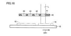
図16~図20は、実施の形態3の露光パターン41,42の切り替え状況を示す模式図である。実施の形態1,2では、第一の照射領域16の露光処理の完了後に露光マスク40を切り替え、露光パターン41から露光パターン42への切り替え完了後に第二の照射領域18の露光処理が開始された。これに対し実施の形態3では、基板10および露光マスク40を共に移動させた状態で、第二の照射領域18の露光処理が開始される。つまり実施の形態3では、露光パターン41から露光パターン42への切り替え中に、第二の照射領域18の露光が開始されている。
図16~図20は、実施の形態3の露光パターン41,42の切り替え状況を示す模式図である。実施の形態1,2では、第一の照射領域16の露光処理の完了後に露光マスク40を切り替え、露光パターン41から露光パターン42への切り替え完了後に第二の照射領域18の露光処理が開始された。これに対し実施の形態3では、基板10および露光マスク40を共に移動させた状態で、第二の照射領域18の露光処理が開始される。つまり実施の形態3では、露光パターン41から露光パターン42への切り替え中に、第二の照射領域18の露光が開始されている。
実施の形態2と同様に、一枚の基板10に第一の照射領域16と第二の照射領域18との両方が設けられている。図16では、基板10を移動方向DR1に移動させながら、基板11の表面の照射領域16に対し、露光パターン41を介して露光光Lが照射されている。このとき露光マスク40は停止している。これにより、露光マスク40に形成された一つの露光パターン41が基板10の第一の照射領域16に転写され、基板10は走査露光される。
図16の状態から基板10が移動を続けることにより、露光光Lが第一の照射領域16の全てに露光された、図17に示す状態になる。基板10の移動方向DR1における第一の照射領域16の後端側に露光光Lが到達したことにより、第一の照射領域16の露光処理が完了した状態となる。このタイミングで、基板10の移動を継続しながら、露光マスク40の移動方向DR2への移動が開始され、露光パターン41から露光パターン42への切り替えが開始される。
露光パターン41,42の切り替えのために露光マスク40を移動方向DR2に移動させるとともに、基板10の移動を継続することで、図18に示す、露光光Lが露光パターン41と露光パターン42との両方を透過して基板10に照射される状態となる。露光光Lが露光パターン42を介して第二の照射領域18に照射されることにより、第二の照射領域18の露光処理が開始される。このとき、露光マスク40を移動しながら、基板10の第二の照射領域18への露光処理が実施されている。
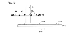
光源30で発生する露光光Lの全てが露光パターン42を介して基板10に照射される位置にまで露光マスク40が到達すると、露光マスク40は停止する。その後、基板10がさらに移動を継続することで、第二の照射領域18の走査露光が継続され、図19に示す状態になる。図19に示す状態から、引き続き、基板10の移動が継続され、第二の照射領域18の走査露光が行なわれる。
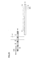
図20には、第二の照射領域18の露光処理を終えた後の、露光パターンを元に戻すための露光マスク40の移動が示されている。基板10の露光処理が完了し、露光可能領域L0が第二の照射領域18を外れると、露光マスク40は図20に示す移動方向DR2へ移動する。これにより、露光可能領域L0が露光パターン42から露光パターン41へと戻り、次の基板の露光処理の準備が行なわれる。
実施の形態3の露光装置によると、第一の照射領域16の露光終了後、露光パターン41,42の切り替え完了を待つことなく、露光パターン41,42の切り替えの途中に次なる第二の照射領域18の露光が開始される。そのため、露光処理に要する時間をより短縮できるので、生産効率をさらに向上することができる。加えて、露光パターン41,42の両方を介して露光光Lを基板10に照射することを許容することにより、第一の照射領域16と第二の照射領域18との間隔を小さくできるので、一枚の基板10のうち露光処理に使用されない領域を低減し、基板10の利用効率を向上することができる。
以上のように本発明の実施の形態について説明を行なったが、今回開示された実施の形態はすべての点で例示であって、制限的なものではないと考えられるべきである。この発明の範囲は上記した説明ではなくて請求の範囲によって示され、請求の範囲と均等の意味、および範囲内でのすべての変更が含まれることが意図される。
1 露光装置、10,11,12 基板、16 第一の照射領域、18 第二の照射領域、20 ステージ、30 光源、40 露光マスク、41,42,43,44 露光パターン、46,47,48 遮蔽領域、50 マスク駆動部、51 本体部、52 駆動軸、53 マスク保持部、80 制御部、DR1 基板の移動方向、DR2 露光マスクの移動方向、L 露光光、L0 露光可能領域。
Claims (6)
- 平板形状の基板と、
前記基板を搭載し、前記基板を前記基板の面方向に移動させるステージと、
前記基板に照射される露光光を発生する光源と、
前記露光光を透過する露光パターンが複数形成され、前記露光パターンを介して前記基板に前記露光光を照射する露光マスクと、
前記露光マスクを前記基板に並行に移動させるマスク駆動部と、を備え、
前記基板は、第一の照射領域と、前記第一の照射領域に対し露光時に前記基板が移動する方向の後方側に設けられた第二の照射領域とを有し、
前記露光パターンは、第一パターンと、前記第一パターンと異なる第二パターンとを含み、
前記ステージにより前記基板を移動しながら前記第一パターンを介して前記第一の照射領域を露光し、前記第一の照射領域の露光終了後、前記基板の移動を継続しながら前記露光マスクを移動して前記第一パターンから前記第二パターンへの切り替えを行ない、前記基板の移動を継続しながら前記第二パターンを介して前記第二の照射領域を露光する、露光装置。 - 前記第一パターンから前記第二パターンへの切り替え中に前記第二の照射領域の露光を開始する、請求項1に記載の露光装置。
- 前記第一パターンから前記第二パターンへの切り替え終了後に前記第二の照射領域の露光を開始する、請求項1に記載の露光装置。
- 請求項1から請求項3のいずれかに記載の露光装置に用いられる露光マスクであって、
前記露光パターンは、前記露光マスクの移動方向に複数並べられている、露光マスク。 - 前記第二パターンは、前記第一パターンに対し、前記基板の露光処理中の移動方向の後方側に設けられている、請求項4に記載の露光マスク。
- 前記露光パターンは、前記露光マスクの移動方向に直交する方向に延びるように形成されており、
前記第一パターンと前記第二パターンとの間には、前記露光光を遮蔽する遮蔽領域が、前記露光マスクの移動方向に直交する方向に延びるように形成されている、請求項4または請求項5に記載の露光マスク。
Applications Claiming Priority (2)
| Application Number | Priority Date | Filing Date | Title |
|---|---|---|---|
| JP2011278206 | 2011-12-20 | ||
| JP2011-278206 | 2011-12-20 |
Publications (1)
| Publication Number | Publication Date |
|---|---|
| WO2013094555A1 true WO2013094555A1 (ja) | 2013-06-27 |
Family
ID=48668445
Family Applications (1)
| Application Number | Title | Priority Date | Filing Date |
|---|---|---|---|
| PCT/JP2012/082641 Ceased WO2013094555A1 (ja) | 2011-12-20 | 2012-12-17 | 露光装置および露光マスク |
Country Status (2)
| Country | Link |
|---|---|
| JP (1) | JPWO2013094555A1 (ja) |
| WO (1) | WO2013094555A1 (ja) |
Cited By (1)
| Publication number | Priority date | Publication date | Assignee | Title |
|---|---|---|---|---|
| CN104538307A (zh) * | 2014-12-19 | 2015-04-22 | 深圳市华星光电技术有限公司 | 一种用于制作多晶硅薄膜晶体管的方法 |
Citations (6)
| Publication number | Priority date | Publication date | Assignee | Title |
|---|---|---|---|---|
| JP2006145745A (ja) * | 2004-11-18 | 2006-06-08 | Dainippon Screen Mfg Co Ltd | パターン描画装置およびパターン描画方法 |
| JP2009204982A (ja) * | 2008-02-28 | 2009-09-10 | Dainippon Screen Mfg Co Ltd | パターン描画装置及びパターン描画方法 |
| WO2009145032A1 (ja) * | 2008-05-28 | 2009-12-03 | 凸版印刷株式会社 | カラーフィルタの製造方法、パターン付き基板の製造方法及び小型フォトマスク |
| JP2010122619A (ja) * | 2008-11-21 | 2010-06-03 | Dainippon Screen Mfg Co Ltd | パターン描画装置、パターン描画方法及びパターン描画用のマスク |
| JP2011164430A (ja) * | 2010-02-10 | 2011-08-25 | Nikon Corp | 露光方法及び装置、並びにデバイス製造方法 |
| JP2012242576A (ja) * | 2011-05-19 | 2012-12-10 | V Technology Co Ltd | フォトマスク及び露光装置 |
Family Cites Families (4)
| Publication number | Priority date | Publication date | Assignee | Title |
|---|---|---|---|---|
| JPH10282638A (ja) * | 1997-04-10 | 1998-10-23 | Nikon Corp | レチクル及びこれを用いた露光装置 |
| JP2005084379A (ja) * | 2003-09-09 | 2005-03-31 | Renesas Technology Corp | フォトマスクおよび半導体装置の製造方法 |
| JP5365274B2 (ja) * | 2009-03-12 | 2013-12-11 | 凸版印刷株式会社 | 露光装置 |
| JP2011134937A (ja) * | 2009-11-30 | 2011-07-07 | Nsk Ltd | 近接スキャン露光装置及びその制御方法 |
-
2012
- 2012-12-17 JP JP2013550267A patent/JPWO2013094555A1/ja active Pending
- 2012-12-17 WO PCT/JP2012/082641 patent/WO2013094555A1/ja not_active Ceased
Patent Citations (6)
| Publication number | Priority date | Publication date | Assignee | Title |
|---|---|---|---|---|
| JP2006145745A (ja) * | 2004-11-18 | 2006-06-08 | Dainippon Screen Mfg Co Ltd | パターン描画装置およびパターン描画方法 |
| JP2009204982A (ja) * | 2008-02-28 | 2009-09-10 | Dainippon Screen Mfg Co Ltd | パターン描画装置及びパターン描画方法 |
| WO2009145032A1 (ja) * | 2008-05-28 | 2009-12-03 | 凸版印刷株式会社 | カラーフィルタの製造方法、パターン付き基板の製造方法及び小型フォトマスク |
| JP2010122619A (ja) * | 2008-11-21 | 2010-06-03 | Dainippon Screen Mfg Co Ltd | パターン描画装置、パターン描画方法及びパターン描画用のマスク |
| JP2011164430A (ja) * | 2010-02-10 | 2011-08-25 | Nikon Corp | 露光方法及び装置、並びにデバイス製造方法 |
| JP2012242576A (ja) * | 2011-05-19 | 2012-12-10 | V Technology Co Ltd | フォトマスク及び露光装置 |
Cited By (4)
| Publication number | Priority date | Publication date | Assignee | Title |
|---|---|---|---|---|
| CN104538307A (zh) * | 2014-12-19 | 2015-04-22 | 深圳市华星光电技术有限公司 | 一种用于制作多晶硅薄膜晶体管的方法 |
| WO2016095308A1 (zh) * | 2014-12-19 | 2016-06-23 | 深圳市华星光电技术有限公司 | 一种用于制作多晶硅薄膜晶体管的方法 |
| US9515190B2 (en) | 2014-12-19 | 2016-12-06 | Shenzhen China Star Optoelectronics Technology Co., Ltd. | Method for manufacturing polysilicon thin film transistor |
| CN104538307B (zh) * | 2014-12-19 | 2018-07-06 | 深圳市华星光电技术有限公司 | 一种用于制作多晶硅薄膜晶体管的方法 |
Also Published As
| Publication number | Publication date |
|---|---|
| JPWO2013094555A1 (ja) | 2015-04-27 |
Similar Documents
| Publication | Publication Date | Title |
|---|---|---|
| KR101727773B1 (ko) | 노광 장치 | |
| JP2011097112A5 (ja) | ||
| JP2011044713A5 (ja) | ||
| KR101308770B1 (ko) | 양면 노광 장치 | |
| CN202372754U (zh) | 一种曝光机及曝光系统 | |
| JP5756813B2 (ja) | 基板露光方法 | |
| WO2013094555A1 (ja) | 露光装置および露光マスク | |
| JP5825470B2 (ja) | 露光装置及び遮光板 | |
| JP5279207B2 (ja) | 露光装置用基板搬送機構 | |
| WO2007132610A1 (ja) | 露光装置 | |
| JP2010026369A (ja) | 近接露光装置 | |
| JP2010092021A (ja) | 露光装置及び露光方法 | |
| JP5225396B2 (ja) | 露光装置、露光方法、及び基板製造方法 | |
| JP5077655B2 (ja) | 近接スキャン露光装置及びエアパッド | |
| JP4942617B2 (ja) | スキャン露光装置 | |
| JP5089257B2 (ja) | 近接スキャン露光装置 | |
| JP4693347B2 (ja) | 露光用シャッター、露光装置、露光方法、及び基板製造方法 | |
| JP5099318B2 (ja) | 露光装置及び露光方法 | |
| JP5089255B2 (ja) | 露光装置 | |
| JP2008040066A (ja) | 露光装置 | |
| KR101941987B1 (ko) | 노광 장치 | |
| JP5089258B2 (ja) | 近接スキャン露光装置及びその露光方法 | |
| JP5084356B2 (ja) | 露光装置用基板搬送機構及びそれを用いた基板位置調整方法 | |
| KR101883186B1 (ko) | 블라인드를 포함하는 노광 장치 및 이의 구동 방법 | |
| CN106292187A (zh) | 曝光方法 |
Legal Events
| Date | Code | Title | Description |
|---|---|---|---|
| 121 | Ep: the epo has been informed by wipo that ep was designated in this application |
Ref document number: 12858785 Country of ref document: EP Kind code of ref document: A1 |
|
| ENP | Entry into the national phase |
Ref document number: 2013550267 Country of ref document: JP Kind code of ref document: A |
|
| NENP | Non-entry into the national phase |
Ref country code: DE |
|
| 122 | Ep: pct application non-entry in european phase |
Ref document number: 12858785 Country of ref document: EP Kind code of ref document: A1 |