WO2013094484A1 - ネックバンド型イヤーホン - Google Patents
ネックバンド型イヤーホン Download PDFInfo
- Publication number
- WO2013094484A1 WO2013094484A1 PCT/JP2012/082161 JP2012082161W WO2013094484A1 WO 2013094484 A1 WO2013094484 A1 WO 2013094484A1 JP 2012082161 W JP2012082161 W JP 2012082161W WO 2013094484 A1 WO2013094484 A1 WO 2013094484A1
- Authority
- WO
- WIPO (PCT)
- Prior art keywords
- neckband
- earphone
- audio signal
- unit
- wearer
- Prior art date
Links
Images


Classifications
-
- H—ELECTRICITY
- H04—ELECTRIC COMMUNICATION TECHNIQUE
- H04R—LOUDSPEAKERS, MICROPHONES, GRAMOPHONE PICK-UPS OR LIKE ACOUSTIC ELECTROMECHANICAL TRANSDUCERS; DEAF-AID SETS; PUBLIC ADDRESS SYSTEMS
- H04R1/00—Details of transducers, loudspeakers or microphones
- H04R1/10—Earpieces; Attachments therefor ; Earphones; Monophonic headphones
- H04R1/105—Earpiece supports, e.g. ear hooks
-
- H—ELECTRICITY
- H04—ELECTRIC COMMUNICATION TECHNIQUE
- H04R—LOUDSPEAKERS, MICROPHONES, GRAMOPHONE PICK-UPS OR LIKE ACOUSTIC ELECTROMECHANICAL TRANSDUCERS; DEAF-AID SETS; PUBLIC ADDRESS SYSTEMS
- H04R5/00—Stereophonic arrangements
- H04R5/033—Headphones for stereophonic communication
-
- H—ELECTRICITY
- H04—ELECTRIC COMMUNICATION TECHNIQUE
- H04R—LOUDSPEAKERS, MICROPHONES, GRAMOPHONE PICK-UPS OR LIKE ACOUSTIC ELECTROMECHANICAL TRANSDUCERS; DEAF-AID SETS; PUBLIC ADDRESS SYSTEMS
- H04R5/00—Stereophonic arrangements
- H04R5/033—Headphones for stereophonic communication
- H04R5/0335—Earpiece support, e.g. headbands or neckrests
-
- H—ELECTRICITY
- H04—ELECTRIC COMMUNICATION TECHNIQUE
- H04R—LOUDSPEAKERS, MICROPHONES, GRAMOPHONE PICK-UPS OR LIKE ACOUSTIC ELECTROMECHANICAL TRANSDUCERS; DEAF-AID SETS; PUBLIC ADDRESS SYSTEMS
- H04R1/00—Details of transducers, loudspeakers or microphones
- H04R1/005—Details of transducers, loudspeakers or microphones using digitally weighted transducing elements
-
- H—ELECTRICITY
- H04—ELECTRIC COMMUNICATION TECHNIQUE
- H04R—LOUDSPEAKERS, MICROPHONES, GRAMOPHONE PICK-UPS OR LIKE ACOUSTIC ELECTROMECHANICAL TRANSDUCERS; DEAF-AID SETS; PUBLIC ADDRESS SYSTEMS
- H04R1/00—Details of transducers, loudspeakers or microphones
- H04R1/10—Earpieces; Attachments therefor ; Earphones; Monophonic headphones
- H04R1/1008—Earpieces of the supra-aural or circum-aural type
-
- H—ELECTRICITY
- H04—ELECTRIC COMMUNICATION TECHNIQUE
- H04R—LOUDSPEAKERS, MICROPHONES, GRAMOPHONE PICK-UPS OR LIKE ACOUSTIC ELECTROMECHANICAL TRANSDUCERS; DEAF-AID SETS; PUBLIC ADDRESS SYSTEMS
- H04R1/00—Details of transducers, loudspeakers or microphones
- H04R1/10—Earpieces; Attachments therefor ; Earphones; Monophonic headphones
- H04R1/1016—Earpieces of the intra-aural type
-
- H—ELECTRICITY
- H04—ELECTRIC COMMUNICATION TECHNIQUE
- H04R—LOUDSPEAKERS, MICROPHONES, GRAMOPHONE PICK-UPS OR LIKE ACOUSTIC ELECTROMECHANICAL TRANSDUCERS; DEAF-AID SETS; PUBLIC ADDRESS SYSTEMS
- H04R1/00—Details of transducers, loudspeakers or microphones
- H04R1/10—Earpieces; Attachments therefor ; Earphones; Monophonic headphones
- H04R1/1041—Mechanical or electronic switches, or control elements
-
- H—ELECTRICITY
- H04—ELECTRIC COMMUNICATION TECHNIQUE
- H04R—LOUDSPEAKERS, MICROPHONES, GRAMOPHONE PICK-UPS OR LIKE ACOUSTIC ELECTROMECHANICAL TRANSDUCERS; DEAF-AID SETS; PUBLIC ADDRESS SYSTEMS
- H04R2460/00—Details of hearing devices, i.e. of ear- or headphones covered by H04R1/10 or H04R5/033 but not provided for in any of their subgroups, or of hearing aids covered by H04R25/00 but not provided for in any of its subgroups
- H04R2460/17—Hearing device specific tools used for storing or handling hearing devices or parts thereof, e.g. placement in the ear, replacement of cerumen barriers, repair, cleaning hearing devices
Definitions
- the present invention relates to a neckband type earphone.
- neckband type earphone is different from the headphone which holds the band portion connecting the driver unit at the top of the head, and the headphone itself is relatively small and has excellent design.
- Neckband type earphones have an earphone driver unit connected at the band.
- the band part has a U-shape, and when the earphone is worn, the band is arranged near the back of the head of the wearer.
- Such neckband earphones are disclosed (for example, see Patent Document 1 and Patent Document 2).
- a neckband type earphone provided with a reproduction unit for reproducing an audio signal behind the neckband is known (for example, see Patent Document 3).
- the playback unit itself is provided in the neckband earphone, it is not necessary to connect the playback device and the neckband earphone with a cable. For example, when the user walks by commuting When you do sports such as jogging, you can concentrate on sports without worrying about cables.
- the playback device includes a transmission unit that outputs the audio signal using the radio wave
- the earphone includes a reception unit that receives the audio signal.
- the neckband earphone is configured to receive an audio signal by radio waves.
- the headphone device disclosed in Patent Document 1 includes a headphone housing in which two driver units for left and right ears are built in a U-shaped band portion.
- the tip of the band part is held on the temporal region near the upper ends of the left and right auricles of the wearer, and the middle part of the band part is disposed on the back of the wearer.
- tip part of a band part protrudes ahead from a wearer's pinna, and the front-end
- the vicinity of the tip of the band portion is in a state of tightening the head of the wearer, and when the headphone device is worn for a long time, the headache of the wearer may be caused.
- the vicinity of the tip of the band portion comes into contact with the vicinity of the temple of the head.
- an elastic material is used for the band part, and the band part is formed so that the tip of the band part firmly contacts the head by the elasticity.
- the headphone device holds the headphone device in contact with the head of the wearer with the band part and the headphone housing, but the portion that contacts the head contacts with a line instead of a surface. A sense of instability in the user, and there is no sense of stability in wearing the headphone device.
- the tip of the band unit protrudes from the headphone device, there is a risk that the ear or the back of the head may be accidentally picked up when the headphone device is used.
- Neckband headphone devices are beginning to become popular, but some people still do not know how to use them. Since the headphone device having the tip has a special shape as a headphone, when using the portable device outside and wearing the headphone device at night, the wearer must attach the tip to the headphone device. There is a risk that the user may forget to hold the headphone device, and that the ear or head is poke at the tip.
- the headphones have a shape in which a headphone housing is provided in a band portion having a tip portion, and the strength of the entire headphone device is low, and the tip portion may be broken and broken.
- the neckband earphone that receives the audio signal reproduced by the playback device by radio waves is provided with a control unit that controls the volume of the audio signal and the power supply in addition to the reception unit that receives the radio wave from the playback device. Battery is required. For this reason, when receiving an audio signal from a playback device by radio waves using a neckband earphone as disclosed in Patent Document 2, it is necessary to provide the above-described receiving unit, control unit, battery, and the like in the housing. The housing becomes heavy. If the housing becomes heavy in this way, for example, when the user walks for commuting or performs sports such as jogging, the neckband earphone may fall off or be displaced from the ear due to the weight of the housing. There is a fear.
- a control unit, a battery, and the like can be provided in the playback unit.
- the weight of the reproducing unit provided at the back of the neckband every time the user's head vibrates. The load is transmitted to the user's head, and the head is tilted rearward due to the weight of the playback unit, so that the wearability of the neckband earphone may be significantly impaired.
- the present invention can be worn for a long time without causing the wearer to feel uncomfortable wearing the neckband earphone, reduces the risk to the wearer during wearing, and reduces the number of breakage points.
- the neckband earphone can prevent the neckband earphone from being displaced from the ear or the wearability being impaired even if the user goes to work or sports with the neckband earphone worn. The purpose is to provide.
- the invention of the present application is an earphone part that is inserted into the wearer's pinna and outputs an audio signal, an ear holder part that is connected to the earphone part and abuts on the upper side of the wearer's pinna, a holder body that includes the ear holder part,
- the neckband type earphone including the earphone driver including the holder main body and the neckband connecting the two earphone drivers
- the holder main body includes a cushion portion at a portion in contact with the head around the ear of the wearer. It is characterized by that.
- the invention of the present application is characterized in that, in the above-described neckband earphone, the cushion portion includes a plurality of convex portions.
- the present invention is characterized in that, in the neckband earphone described above, the convex portion of the cushion portion is hollow inside or a loading member is injected therein.
- the invention of the present application is characterized in that, in the neckband earphone described above, the convex portion of the cushion portion has a circular shape or a polygonal shape.
- the convex part of the cushion part is a mixture of a circular convex part and a polygonal convex part.
- the present invention relates to a neckband earphone that outputs an audio signal, a neckband portion that is formed of an elastic body and forms a curve, a driver unit having a diaphragm that is fixed to a housing and emits an audio signal, A head holding portion connected to a neckband portion for outputting an audio signal to the driver unit; and an arm portion formed of a curved elastic body for connecting the head holding portion and the housing.
- a plurality of dimple portions each having a concave shape on a side surface are provided.
- the present invention is characterized in that the dimple portion is formed of an elastic body in the neckband earphone described above.
- the head holding unit includes an audio signal receiving unit that receives an audio signal, and an audio signal output unit that outputs the audio signal received by the audio signal receiving unit to the driver unit. It is characterized by providing.
- the invention of the present application can be worn for a long time without giving the wearer the discomfort of wearing the neckband earphone in the neckband earphone, and also reduces the risk to the wearer at the time of wearing and breaks.
- the number of locations can be reduced, and even if the user performs commuting or sports while wearing the neckband earphone, the neckband earphone can be prevented from being displaced from the ear or the wearability being impaired.
- a neckband earphone can be provided.
- FIG. 6 is an AA cross-sectional view showing a housing 300 and an ear pad 400 of the neckband earphone 100 shown in FIG. 5.
- FIG. 6 is a BB cross-sectional view showing the head holding unit 200 of the neckband earphone 100 shown in FIG. 5.
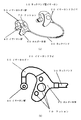
- FIG. 1 is a diagram showing a schematic configuration of a neckband earphone according to a first embodiment of the present invention.
- FIG. 1A is a diagram illustrating a schematic configuration of the entire neckband earphone
- FIG. 1B is a diagram illustrating a schematic configuration of an earphone driver of the neckband earphone.
- the neckband type earphone 10 includes two earphone drivers 20 and a neckband 30.
- the neckband 30 has a U-shape, and earphone drivers 20 are provided at two ends thereof.
- the U-shape of the neckband 30 has a shape in which both ends are slightly curved inward.
- Two earphone drivers 20 are provided on the ears of the wearer, the neckband 30 is disposed on the back side of the neck of the wearer, and the neckband earphone 10 is worn on the wearer.
- the earphone driver 20 includes an earphone section 40, an ear holder section 50, and a holder main body 60.
- the earphone unit 40 is inserted into the wearer's pinna and outputs an audio signal.
- the ear holder unit 50 connects the earphone unit 40 and a holder main body 60 described later, and contacts the upper side of the wearer's pinna to hold the neckband earphone 10.
- the holder body 60 incorporates a driver (not shown) that converts an electrical signal into an audio signal, holds the earphone part 40 via the ear holder part 50, and contacts the head part around the ears of the wearer.
- a cushion part 70 is provided.
- the ear holder 50 of the earphone driver 20 contacts the upper side of the wearer's auricle, and the holder body 60 contacts the head on the rear side of the wearer's auricle. Since both ends of the shaped neckband 30 are curved inward, the neckband earphone 10 is held on the head of the wearer.
- FIG. 2 is a view for explaining the structure of the cushion part of the neckband earphone according to the first embodiment of the present invention.
- FIG. 2 (a) is a cross-sectional view showing a hollow type cushion part.
- b) is a sectional view showing a cushion portion filled with a filling member.
- a holder main body 60 of the earphone driver 20 shown in FIG. 2B includes a cushion portion 70 formed of a specific number of convex portions 80. As described above, when the earphone driver 20 is mounted on the wearer's auricle, the cushion unit 70 comes into contact with the head on the back side of the wearer's auricle. The cushion part 70 provided to the head directly contacts the wearer's head.
- the convex part 80 of the cushion part 70 is formed of an elastomer member. As shown in FIG. 2A, the convex portion 80 has a hollow portion 81 therein and is filled with air.
- the cushion part 70 is made of a soft material such as an elastomer material so that the cushion part 70 is made hollow and comes into contact with the head so that the convex part 80 of the cushion part 70 is crushed when touched by the wearer. A feeling of adhesion is obtained as well as a feeling.
- it since it is a soft material, a wearer can endure long-time wearing, without giving a pain to a wearer.
- the boulder body 60 itself can be easily manufactured.
- the convex portion 80 of the cushion portion 70 may be filled with a filling member 82 such as gel-like silicon.
- a filling member 82 such as gel-like silicon.
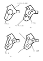
- FIG. 3 is a diagram illustrating another example of the cushion portion in the neckband earphone according to the first embodiment of the present invention.
- the cushion portion 70 is composed of three convex portions 80 and may be composed of one convex portion 80 as shown in FIG.
- 3 (b) you may be comprised by the 2 or more some convex part 80.
- the cushion portion 70 having at least one convex portion 80 can obtain a stable wearing feeling without causing discomfort to the wearing person, and for a long time. Can be installed.
- the convex part 80 of the cushion part 70 may be a combination of one large convex part 80 and a convex part 80 having a smaller size as shown in FIG. 1, and as shown in FIG. You may make it comprise the convex part 80 of the same magnitude
- the cushion portion 70 By configuring the cushion portion 70 with a plurality of convex portions 80 of the same size, the plurality of convex portions 80 come into contact with the head with the same pressure, thereby obtaining a stable wearing feeling in contact with uniform pressure. it can.
- the convex part 80 of the cushion part 70 is comprised by the convex part 80 of the circular convex part 80 and the polygon (a triangle, a tetragon
- the convex portion 80 having a polygonal shape instead of a circular shape the surface having the polygonal side has a restraining force in the movement in the direction of the surface, and the contact surface is displaced from the head of the holder body 60. It becomes prevention of.
- the convex part 80 of the cushion part 70 may be made to form the convex part 80 by various arrangement
- the cushion portion 70 can be configured with various shapes of convex portions 80 in various arrangements as appropriate according to the intended use of the neckband earphone 10.
- the number of the convex portions 80 of the cushion portion 70 is increased, and the shape of the convex portion 80 is made polygonal so that it can be exercised. This prevents the neckband earphone 10 from being displaced from the head due to the vibration of the head.
- the circular convex portion 80 is formed, and the cushion portion 70 constituted by a small number of convex portions 80 is used, so that the head portion can be obtained. It is possible to withstand long-time wearing without giving much contact feeling, and to obtain a stable wearing feeling.
- the neckband earphone 10 of the present embodiment causes the neckband earphone 10 to be firmly attached to the wearer's head by the cushion portion 70 of the holder portion 60 together with the ear holder portion 50 of the earphone driver 20.
- the neckband earphone 10 can be worn for a long time with a stable wearing feeling without the wearer getting uncomfortable feeling. Can be worn.
- the neckband type earphone 10 does not have a protruding tip portion of the neckband 30 used for wearing, even a person who does not know how to use the neckband type earphone 10 wears the neckband type earphone 10. When doing so, there is no danger of poke the ear or head at the tip.
- the neckband type earphone 10 does not have a protruding tip portion of the neckband 30 used when being worn, the tip portion is not broken and broken.
- the neckband earphone 10 of the present embodiment can be worn for a long time without giving the wearer the discomfort of wearing the neckband earphone 10, and the danger to the wearer at the time of wearing is also possible.
- FIG. 4 is a schematic configuration diagram showing a neckband earphone according to a second embodiment of the present invention.
- the neckband earphone 100 includes two head holding units 200, two housings 300, two ear pads 400, two arm units 500, and a neckband unit 600.
- the neckband portion 600 is formed of an elastic body such as a curved rubber member, and includes connection portions 601 that connect the head holding portion 200 to both ends.
- the head holding unit 200 is connected to the connection unit 601.
- the two head holding portions 200, the housing 300, the ear pad 400, and the arm portion 500 are arranged so as to be symmetrical with respect to the neckband portion 600.
- the head holding unit 200 includes an operation unit 800 on a surface that is on the outer side with respect to the neckband unit 600.
- the arm portion 500 is made of an elastic body such as a rubber member, and forms a cylindrical shape with a hollow inside. One end of the arm unit 500 is fixed to the upper surface portion of the head holding unit 200 and the housing 300 is fixed to the other end.
- the housing 300 holds the ear pad 400 on the inner surface of the neckband portion 600.
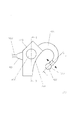
- FIG. 5 is a side view showing the head holding part 200, the arm part 500, and the housing 300 of the neckband earphone 100 according to the second embodiment of the present invention.
- the upward direction is above the neckband earphone 100
- the right direction is the front of the neckband earphone 100.
- the arm part 500 is formed in a state of being curved in a substantially semicircular shape.
- the head holding portion 200 has a curved surface portion 208 formed on the front surface.
- the curved inner surface of the arm unit 500 is disposed in a state of being smoothly continuous with the curved surface of the curved surface unit 208.
- the arm portion 500 is configured to be deformable in the arrow direction by pressing the housing 300 forward or backward due to the elasticity of the elastic body.
- FIG. 6 is a cross-sectional view taken along the line AA showing the housing 300 and the ear pad 400 of the neckband earphone 100 shown in FIG.
- the upper direction is above the housing 300 and the ear pad 400
- the right direction is the inside of the housing 300 and the ear pad 400.
- the housing 300 includes a driver unit 700 inside.
- the housing 300 forms a cylindrical shape having a hollow portion 302 therein, and has a hole 301 in the upper part.
- the hole 301 penetrates the hollow portion inside the arm unit 500.
- the housing 300 includes a convex portion 304 that is formed in a cylindrical shape in the inner portion and includes a hole 303 that penetrates inward from the cavity portion 302.
- the convex part 304 is provided with a groove part 305 in the central part of the outer periphery.
- the driver unit 700 includes a vibration plate (not shown), and is fixed to the inner wall of the housing 2 with an adhesive or the like so that the vibration plate is exposed from the hole 303 to the inside.
- the lead wire 140 is electrically connected to the driver unit 700.
- the lead wire 140 is electrically connected to an audio signal output unit of the head holding unit 200 described later via a hole 301 and through a cavity inside the arm unit 500.
- the ear pad 400 is formed in a cylindrical shape by an elastic body such as a rubber member, and includes a hole 401 penetrating in the front-rear direction.
- the ear pad 400 includes a flange portion 402 protruding in the inner circumferential direction.
- the ear pad 400 is held inside the housing 300 by fitting the collar portion 402 into the groove portion 305 of the convex portion 303.
- FIG. 7 is a BB cross-sectional view showing the head holding part 200 of the neckband earphone 100 shown in FIG. In FIG. 7, the upward direction is above the head holding unit 200, and the right direction is the inside of the head holding unit 200.
- the head holding unit 200 includes a chassis unit 201, a cover unit 203, a contact unit 206, a substrate 900, a switch 1000, an audio signal receiving unit 110, a control unit 120, an audio signal output unit 130, and a battery 150. Is provided.
- the chassis unit 201 forms a box shape that opens to the outside, and includes a recess 202.
- the cover part 203 has a plate shape and is fixed so as to cover the recess 202 from the outside of the chassis part 201.
- the substrate 900 is held inside the recess 202 by a boss 205 fixed to the inner wall of the chassis unit 201, and fixes the switch 1000, the audio signal receiving unit 110, the control unit 120, and the audio signal output unit 130.
- the battery 150 supplies power to the switch 1000, the audio signal receiving unit 110, the control unit 120, and the audio signal output unit 130 through the substrate 900.
- the battery 150 is configured to be provided inside the chassis unit 201 and the cover unit 203, but may be configured to be detachable from the lower surface of the chassis unit 201, and the cover unit 203 includes an opening / closing cover.
- the battery 150 provided inside the chassis unit 201 may be detachable.
- the audio signal receiving unit 110 receives an audio signal transmitted by radio waves from a playback device (not shown).
- the operation unit 800 includes a shaft on the inner side, and the shaft is connected to a switch 1000 fixed to the substrate 900 through a hole 204 provided in the cover unit 203.
- the switch 1000 outputs an audio signal playback start or playback stop instruction signal when the operation unit 800 is pressed inward.
- the control unit 120 controls the audio signal receiving unit 110 and the audio signal output unit 130. Based on the instruction signal from the switch 1000, the control unit 120 controls the audio signal output unit 130 to start or stop outputting the audio signal received by the audio signal receiving unit 110.
- the audio signal output unit 130 is electrically connected to the driver unit 700 provided in the housing 300 through the lead wire 140 as described above, and the audio signal received by the audio signal receiving unit 110 based on the control of the control unit 120. A signal is output to the driver unit 700.
- the contact portion 206 is made of a plate-like elastic body such as a rubber member, and is fixed to the inner side surface of the chassis portion 201. As shown in FIGS. 4 and 7, the contact portion 206 includes a plurality of dimple portions 207 each having a concave shape on the inner surface.
- the neckband portion 600 is attached to the user's head, the curved surface portion 208 of the head holding portion 200 is brought into contact with the back of the earlobe and the arm portion.
- the ear pad 400 is fitted into the ear with 500 being put on the top of the ear.
- the neckband type earphone 100 has a head that is sandwiched between the user's left and right ears by the contact part 206 of the head holding part 200 due to the elasticity of the neckband part 600 and abutted against the rear part of the earlobe by the elasticity of the arm part 500.
- the ear is sandwiched between the curved surface portion 208 and the ear pad 400 of the holding portion 200. Accordingly, the neckband earphone 100 is attached to the user's head and ears.
- the playback device (not shown) is operated so that the audio signal is transmitted by radio waves from the transmission unit of the playback device.
- the neckband earphone 100 When an audio signal is transmitted by radio waves from the transmission unit of the playback device, the neckband earphone 100 inputs an audio signal transmitted by radio waves from the transmission unit of the playback device by the audio signal reception unit 110.
- the control unit 120 controls the audio signal output unit 130 to output the audio signal input by the audio signal receiving unit 110 when the operation unit 800 is pressed by the user and an instruction signal instructing reproduction is output from the switch 1000.
- the audio signal output unit 130 outputs the audio signal input from the audio signal receiving unit 110 to the driver unit 700 via the lead wire 140 based on the control of the control unit 120.
- the driver unit 700 converts the audio signal input from the audio signal output unit 130 into a vibration by a magnetic circuit, and transmits the vibration to a diaphragm via a voice coil (not shown) to emit the audio signal.
- the audio signal reproduced by the reproduction apparatus is emitted by the driver unit 700 via the audio signal receiving unit 110, the audio signal output unit 130, and the lead wire 140, and the emitted audio signal is output from the hole of the housing 300.
- This is transmitted to the inside of the ear pad 400 via 303.
- the audio signal is transmitted to the ear of the user wearing the ear pad 400, and the user can listen to the audio signal output from the neckband earphone 100.
- the neckband earphone 100 has the back of the user's left and right ears sandwiched by the contact part 206 of the head holding part 200 due to the elasticity of the neckband part 600, and the rear part of the earlobe due to the elasticity of the arm part 500.
- the neckband earphone 100 can be accurately attached to the user's head and ear.
- the contact portion 206 that comes into contact with the rear of the left and right ear portions of the user is provided with a plurality of dimple portions 207 each having a concave shape on the surface thereof, so that the surface of the head portion behind the user's ear portion can be dimpled. It is in a state of being gripped by the recess 207. Therefore, even if the head holding unit 200 includes the audio signal receiving unit 110, the audio signal output unit 130, the battery 150, and the like for receiving the audio signal transmitted from the playback device, the dimple of the contact unit 206 is provided.
- the neckband earphone 100 When the unit 207 holds the surface of the user's head in a gripped state, for example, even if the user wears the neckband earphone 100 and performs sports such as walking or jogging by commuting, the neckband earphone It is possible to prevent 100 from falling off or slipping from the ear.
- the neckband earphone 100 also includes various circuits and a battery 150 for receiving an audio signal transmitted from the playback device and outputting the audio signal to the driver unit 700 as an audio signal.
- the neckband earphone 100 By providing the inside of the head holding unit 200 that comes into contact with the surface of the unit, for example, the user's head vibrates up and down by performing sports such as walking and jogging by commuting while wearing the neckband earphone 100 Even so, the arm portion 500 and the dimple portion 207 of the contact portion 206 cause the weight of the head holding portion 200 to be distributed and evenly distributed to the peripheral portion of the user's ear. It can be continuously attached accurately.
- the neckband earphone 100 for example, a headband by vibration in the vertical direction of the neckband earphone, such as a neckband earphone provided with various circuits and a battery in the rear portion of the neckband portion. It is possible to prevent the wearability of the neckband type earphone from being impaired due to the tilting forward or backward.
- the neckband earphone 100 of the present embodiment includes an operation unit 800 on the outer side surface of the head holding unit 200, and the user can play or stop the audio signal when the user presses the operation unit 800.
- the user presses the dimple part 207 of the contact part 206 against the user's head every time the operation part 800 is pressed in order to start or stop the reproduction of the audio signal.
- the user can press the operation unit 800 and the head surface of the rear part of the user's ear can be newly grasped in the dimple of the dimple unit 207.
- the band-type earphone 100 can be securely attached to the user's head.
- the neckband earphone 100 of the present embodiment has a configuration in which the contact portion 206 including the dimple portion 207 is formed of an elastic body.
- the contact portion 206 may be a metal member or a plastic member other than the elastic body. Thereby, since various coloring and decoration can be given to the contact part 206, the beauty
- the neckband earphone 100 of the present embodiment is configured to receive an audio signal transmitted by radio waves from the playback device by the audio signal receiving unit 110, but the audio signal is transmitted from the playback device by infrared rays or other data transmission means.
- the audio signal transmitted by these transmitting means may be received by the audio signal receiving unit.
- the audio signal may be input through a cable or the like without receiving the audio signal from the reproduction apparatus by wireless means such as radio waves.
- the neckband earphone 100 of the present embodiment is configured to output an audio signal reproduction start or reproduction stop instruction signal when the operation unit 800 of the head holding unit 200 is pressed, but other than the reproduction start or stop In addition, for example, it may be configured such that instructions such as volume adjustment of an audio signal output from the driver unit 700, designation of a reproduction track, designation of a reproduction tempo, and the like can be performed.
- the neckband earphone 100 of the present embodiment is configured such that a playback device that plays back an audio signal is another device other than the neckband earphone 100 and receives an audio signal transmitted from the playback device.
- the head holding unit 200 of the band-type earphone 100 may include a storage unit that stores an audio signal and a playback unit, and the playback unit may play back the audio signal stored in the storage unit.
- the audio signal can be heard only by the neckband type earphone without providing another playback device other than the neckband type earphone 100. Therefore, when the user performs sports such as walking or jogging by commuting. You can concentrate on sports without worrying about connecting cables.
- the present invention can be usefully used for a neckband type earphone.
- neckband earphones 10 neckband earphones, 20 earphone drivers, 30 neckbands, 40 earphones, 50 ear holders, 60 holder body, 70 cushion part, 80 convex part, 81 hollow part, 82 filling member, 100 neckband earphones, 200 head holder, 201 chassis, 202 recess, 203 cover, 204 holes, 205 boss, 206 contact portion, 207 dimple portion, 208 curved surface portion, 300 housing, 301 hole, 302 cavity, 303 hole, 304 convex portion, 305 groove portion, 400 ear pads, 401 holes, 402 buttocks, 500 arm part, 600 neckband part, 601 connection part, 700 Driver unit, 800 operation unit, 900 board, 1000 switch, 110 audio signal receiving unit, 120 control unit, 130 audio signal output unit, 140 lead wire, 150 battery
Abstract
【課題】装着者にネックバンド型イヤーホンの装着の不快感を与えることなく長時間装着することができ、また、装着時の装着者への危険を低減し、破損する箇所を少なくしたネックバンド型イヤーホンを提供すことを目的とする。 【解決手段】装着者の耳介に挿入されオーディオ信号を出力するイヤーホン部と、イヤーホン部に接続し装着者の耳介の上側に当接するイヤーホルダー部と、イヤーホルダー部を備えるホルダー本体と、ホルダー本体を備えるイヤーホンドライバーと、2つのイヤーホンドライバーを接続するネックバンドとを備えるネックバンド型イヤーホンにおいて、ホルダー本体は、装着者の耳介周辺の頭部と接触する部分にクッション部を備える。
Description
本発明は、ネックバンド型イヤーホンに関する。
近年になり、ポータブルオーディオ再生装置用のイヤーホンとして、インナーイヤー型イヤーホン、ネックバンド型イヤーホンなどが普及し始めている。このうち、ネックバンド型イヤーホンは、ドライバーユニットを連結するバンド部を頭頂部で保持するヘッドホンと異なり、ヘッドホン自体が比較的小さく、デザイン性に優れている。
ネックバンド型イヤーホンは、イヤーホンのドライバーユニットがバンド部で連結される。バンド部は、U字状の形状を有し、イヤーホンを装着した際に、バンドが装着者の後頭部付近に配置される。このようなネックバンド型イヤーホンが開示されている(例えば、特許文献1及び特許文献2参照)。
また、他の従来のイヤーホンとして、オーディオ信号を再生する再生部をネックバンドの後方に備えたネックバンド型イヤーホンが知られている(例えば、特許文献3参照)。このような従来のネックバンド型イヤーホンは、再生部自体をネックバンド型イヤーホンが備えることによって、再生装置とネックバンド型イヤーホンをケーブルによって接続する必要がないため、例えば、ユーザが通勤で歩行する場合やジョギングなどのスポーツを行う場合にケーブルを気にせずにスポーツに集中することができる。
また、近年、再生装置からイヤーホンにオーディオ信号を送信する手段として、従来のケーブルを介して再生装置からオーディオ信号をイヤーホンに送信する替わりに、電波によってオーディオ信号を送信する装置が知られている。このような電波によってオーディオ信号を送信する装置においては、再生装置にオーディオ信号を電波によって出力する送信部を備え、一方、イヤーホンにオーディオ信号を受信する受信部を備えることにより、再生装置によって再生したオーディオ信号を電波によってネックバンド型イヤーホンが受信する構成となっている。
特許文献1に開示されているヘッドホン装置は、左右の耳用の2つのドライバユニットが内蔵されたヘッドホンハウジングが、U字状のバンド部に備えられている。バンド部は、先端部が装着者の左右の耳介の上端付近の側頭部に保持され、バンド部の中間部が装着者の後頭部に配置される。そして、バンド部の先端部は、装着者の耳介より前方に突出し、バンド部の先端部付近が装着者の頭部に当接し、ヘッドホン装置全体を装着者の頭部にしっかりと装着させる。
しかし、当該ヘッドホン装置は、バンド部の先端部付近が装着者の頭部を締め付ける状態となり、ヘッドホン装置を長時間装着した場合に装着者の頭痛を引き起こすことがある。当該ヘッドホン装置は、バンド部の先端付近が頭部のこめかみ付近に当接する。また、ヘッドホン装置を頭部にしっかりと装着させるためには、バンド部に弾力性のある素材を用い、その弾力によりバンド部の先端部が頭部にしっかりと当接するようにバンド部が形成される。これらのことから、ヘッドホン装置を装着者の頭部に装着した場合、バンド部が頭部を締め付ける状態となり、当該ヘッドホン装置を長時間装着することに適さない。
また、当該ヘッドホン装置は、バンド部とヘッドホンハウジングが装着者の頭部に接触して当該ヘッドホン装置を頭部に保持するが、頭部に当接する部分が面ではなく線で接触するため、装着者に不安定感を生じさせることになり、ヘッドホン装置の装着の安定感がない。
また、当該ヘッドホン装置は、バンド部の先端が突出しているため、ヘッドホン装置を使用する際に誤って耳や後頭部をつついてしまうなどの危険がある。ネックバンド型のヘッドホン装置は普及し始めているが、まだその使用方法がわからない人もいる。先端部を有する当該ヘッドホン装置は、ヘッドホンとしての形状が特殊な形状であるため、ポータブル装置を外で利用し、夜間に当該ヘッドホン装置を装着する際、装着者が、当該ヘッドホン装置が先端部を有することを失念し、当該ヘッドホン装置を装着する際に、先端部で耳や頭部をつついてしまうという危険がある。
さらに、当該ヘッドホンは、先端部を有するバンド部にヘッドホンハウジングが備えられている形状であり、ヘッドホン装置全体の強度が低く、先端部が折れて破損する可能性がある。
再生装置が再生したオーディオ信号を電波によって受信するネックバンド型イヤーホンは、再生装置からの電波を受信する受信部を備える以外にも、オーディオ信号の音量等を制御する制御部、電源を供給するためのバッテリー等が必要となる。このため、特許文献2に開示されているようなネックバンド型イヤーホンによって再生装置からオーディオ信号を電波によって受信する場合は、前述した受信部、制御部及びバッテリー等をハウジング内に備える必要があるため、ハウジングが重くなってしまう。このようにハウジングが重くなってしまうと、例えば、ユーザが通勤で歩行する場合やジョギングなどのスポーツを行っている間に、ハウジングの重量によってネックバンド型イヤーホンが脱落したり、耳からズレてしまう虞がある。
また、特許文献3に開示されているような再生部をネックバンドの後方に備えるネックバンド型イヤーホンにおいては、制御部及びバッテリー等をこの再生部内に備えることができるが、頭部の後方部分にこのような再生部を頭部に保持した状態で、ユーザが通勤による歩行を行ったりジョギングなどのスポーツを行うと、ユーザの頭部が振動する毎にネックバンドの後方に備える再生部の重量の負荷がユーザの頭部に伝達してしまい、この再生部の重量によって頭部が後方に傾いてしまい、ネックバンド型イヤーホンの装着性が著しく損なわれてしまう虞がある。
したがって、本願発明は、装着者にネックバンド型イヤーホンの装着の不快感を与えることなく長時間装着することができ、また、装着時の装着者への危険を低減し、破損する箇所を少なくし、また、ユーザがネックバンド型イヤーホンを装着した状態で通勤やスポーツ等を行っても、ネックバンド型イヤーホンが耳からズレたり装着性が損なわれてしまうことを防止することができるネックバンド型イヤーホンを提供することを目的とする。
本願発明は、装着者の耳介に挿入されオーディオ信号を出力するイヤーホン部と、イヤーホン部に接続し装着者の耳介の上側に当接するイヤーホルダー部と、イヤーホルダー部を備えるホルダー本体と、前記ホルダー本体を備えるイヤーホンドライバーと、2つのイヤーホンドライバーを接続するネックバンドとを備えるネックバンド型イヤーホンにおいて、ホルダー本体は、装着者の耳介周辺の頭部と接触する部分にクッション部を備えたことを特徴とする。
また、本願発明は、前述したネックバンド型イヤーホンにおいて、クッション部は、複数の凸部からなることを特徴とする。
また、本願発明は、前述したネックバンド型イヤーホンにおいて、クッション部の凸部は、内部が中空であること、或いは、内部に装填部材が注入されていることを特徴とする。
また、本願発明は、前述したネックバンド型イヤーホンにおいて、クッション部の凸部は、円形の形状をしている、または、多角形の形状をしていることを特徴とする。
また、本願発明は、前述したネックバンド型イヤーホンにおいて、クッション部の凸部は、円形の凸部と多角形の凸部が混在することを特徴とする。
また、本願発明は、オーディオ信号を出力するネックバンド型イヤーホンにおいて、弾性体により形成され湾曲を形成するネックバンド部と、ハウジングに固着しオーディオ信号を放音する振動板を有するドライバーユニットと、前記ネックバンド部に接続され前記ドライバーユニットにオーディオ信号を出力するヘッド保持部と、湾曲を成した弾性体により形成され前記ヘッド保持部と前記ハウジングを接続するアーム部とを備え、ヘッド保持部は、側面に凹型を形成した複数のディンプル部を備えることを特徴とする。
また、本願発明は、前述したネックバンド型イヤーホンにおいて、ディンプル部は、弾性体により形成されていることを特徴とする。
また、本願発明は、前述したネックバンド型イヤーホンにおいて、ヘッド保持部は、オーディオ信号を受信するオーディオ信号受信部と、オーディオ信号受信部が受信したオーディオ信号をドライバーユニットに出力するオーディオ信号出力部とを備えることを特徴とする。
本願発明は、ネックバンド型イヤーホンにおいて、装着者にネックバンド型イヤーホンの装着の不快感を与えることなく長時間装着することができ、また、装着時の装着者への危険を低減し、破損する箇所を少なくし、また、ユーザがネックバンド型イヤーホンを装着した状態で通勤やスポーツ等を行っても、ネックバンド型イヤーホンが耳からズレたり装着性が損なわれてしまうことを防止することができるネックバンド型イヤーホンを提供することができる。
(第1の実施の形態)
以下、本発明の第1の実施の形態を図面に基づいて説明する。
図1は、本発明の第1実施例のネックバンド型イヤーホンの概略構成を示す図である。図1(a)は、ネックバンド型イヤーホン全体の概略構成を示す図であり、図1(b)は、ネックバンド型イヤーホンのイヤーホンドライバーの概略構成を示す図である。
図1(a)において、ネックバンド型イヤーホン10は、2つのイヤーホンドライバー20、ネックバンド30を備える。ネックバンド30は、U字形状を有し、その2つの端部にイヤーホンドライバー20が備えられる。なお、ネックバンド30のU字形状は、その両端が少し内側に湾曲する形状を有している。2つのイヤーホンドライバー20が装着者の耳介に備えられ、ネックバンド30は装着者の首の後ろ側に配置され、ネックバンド型イヤーホン10が装着者に装着される。
図1(b)において、イヤーホンドライバー20は、イヤーホン部40、イヤーホルダー部50、ホルダー本体60を備える。イヤーホン部40は、装着者の耳介に挿入され、オーディオ信号を出力する。イヤーホルダー部50は、イヤーホン部40と後述するホルダー本体60とを接続し、装着者の耳介の上側に接触してネックバンド型イヤーホン10を保持する。ホルダー本体60は、電気信号をオーディオ信号に変換するドライバー(図示せず)を内蔵し、イヤーホルダー部50を介してイヤーホン部40を保持すると共に、装着者の耳介周辺の頭部と接触するクッション部70を備える。
ネックバンド型イヤーホン10は、イヤーホンドライバー20のイヤーホルダー部50が装着者の耳介の上側に接触すると共に、ホルダー本体60が装着者の耳介の後ろ側周辺の頭部に接触し、U字形状のネックバンド30の両端が内側に湾曲していることにより、ネックバンド型イヤーホン10が装着者の頭部に保持される。
図2は、本発明の第1実施例のネックバンド型イヤーホンのクッション部の構造を説明する図であり、図2(a)は、中空タイプのクッション部を示す断面図であり、図2(b)は、充填部材を充填したクッション部を示す断面図である。
図2(b)に示すイヤーホンドライバー20のホルダー本体60は、特数の凸部80からなるクッション部70を備えている。当該クッション部70は、前述したとおり、イヤーホンドライバー20が装着者の耳介に装着されると、ホルダー部60が装着者の耳介の後ろ側の頭部に接触し、そのとき、ホルダー部60に備えられているクッション部70が装着者の頭部に直接接触する。
図2(b)に示すイヤーホンドライバー20のホルダー本体60は、特数の凸部80からなるクッション部70を備えている。当該クッション部70は、前述したとおり、イヤーホンドライバー20が装着者の耳介に装着されると、ホルダー部60が装着者の耳介の後ろ側の頭部に接触し、そのとき、ホルダー部60に備えられているクッション部70が装着者の頭部に直接接触する。
クッション部70の凸部80は、エストラマー部材により形成されている。凸部80は、図2(a)に示すとおり、内部に中空部81を有し、空気が充填されている。クッション部70の素材に、エストラマー部材の柔らかい素材を用い中空にすることにより、装着者に接触した際にクッション部70の凸部80が押しつぶされるように頭部に接触し、装着者に柔らかい装着感が得られると共に、密着感が得られる。また、柔らかい素材であるため、装着者に痛みを与えることなく、装着者が長時間の装着にも耐えることができる。更に、中空部の成形が容易であるため、ボルダー本体60自体の製造も容易である。
また、図2(b)に示すとおり、クッション部70の凸部80は、内部にジェル状のシリコンなどの充填部材82を注入するようにしてよい。ジェル状の充填部材82を用いることにより、クッション部70の凸部80の形状が装着者の頭部の形状にあった方に変形した状態を維持し、更に装着感と密着感を向上させることができる。
図3は、本発明の第1実施例のネックバント型イヤーホンにおけるクッション部の他の例を説明する図である。
クッション部70における凸部80の数、大きさ、配置、形状等については、さまざまな組み合わせが可能である。
図1に示すとおり、クッション部70は、3つの凸部80から構成されるほか、図3(a)に示すとおり、1つの凸部80で構成されていてもよく、また、図1や図3(b)に示すとおり、2つ以上の複数の凸部80で構成されていてもよい。少なくとも1つの凸部80を有するクッション部70により、装着者がネックバンド型イヤーホン10を装着した際に、装着者に不快感を与えることなく安定した装着感を得ることができ、そして、長時間の装着を可能にすることができる。
クッション部70における凸部80の数、大きさ、配置、形状等については、さまざまな組み合わせが可能である。
図1に示すとおり、クッション部70は、3つの凸部80から構成されるほか、図3(a)に示すとおり、1つの凸部80で構成されていてもよく、また、図1や図3(b)に示すとおり、2つ以上の複数の凸部80で構成されていてもよい。少なくとも1つの凸部80を有するクッション部70により、装着者がネックバンド型イヤーホン10を装着した際に、装着者に不快感を与えることなく安定した装着感を得ることができ、そして、長時間の装着を可能にすることができる。
また、クッション部70の凸部80は、図1に示すとおり、1つの大きい凸部80と、それより小さいサイズの凸部80との組み合わせでもよく、また、図3(b)に示すとおり、同じ大きさのサイズの凸部80で構成されるようにしてもよい。同じ大きさの複数の凸部80でクッション部70を構成することにより、複数の凸部80が同じ圧力で頭部に接触することにより、均一の圧力で接触した安定した装着感を得ることができる。
また、クッション部70の凸部80は、図3(c)に示すとおり、円形の凸部80と多角形(三角形、四角形、または、それ以上の多角形)の凸部80で構成されていてもよい。更に、凸部80は、図3(c)に示すとおり、多角形(三角形、四角形、または、それ以上の多角形)の凸部80のみで構成されていてもよい。円形ではなく、多角形の形状の凸部80を備えることにより、多角形の辺を有する面が、その面の方向に対する移動に抑制力が生じ、ホルダー本体60の頭部との接触面のずれの防止になる。
また、クッション部70の凸部80は、図3(b)や図3(d)に示すとおり、凸部80をさまざまな配置で形成するようにしてもよい。クッション部70は、ネックバンド型イヤーホン10の使用用途に応じて、適宜、さまざまな形状の凸部80をさまざまな配置で構成することができる。
例えば、スポーツ等に利用することが可能なネックバンド型イヤーホン10の場合は、クッション部70の凸部80の数を多くし、また、凸部80の形状を多角形にすることにより、運動に伴う頭部の振動によるネックバンド型イヤーホン10の頭部からのずれの防止になる。
一方、激しい振動がなく、長時間ネックバンド型イヤーホン10を装着する用途の場合、円形の凸部80であり、少数の数の凸部80で構成したクッション部70にすることにより、頭部への接触感をあまり与えず長時間の装着に耐えることができ、且つ、安定した装着感を得ることができる。
以上のように、本実施例のネックバンド型イヤーホン10は、イヤーホンドライバー20のイヤーホルダー部50と共にホルダー部60のクッション部70により、装着者の頭部にしっかりとネックバンド型イヤーホン10を装着させることができると共に、ネックバンド30の先端部付近が装着者の頭部を締め付けることがないため、装着者が、不快感を得ることなく、安定した装着感で、長時間、ネックバンド型イヤーホン10を装着することができる。
また、ネックバンド型イヤーホン10は、装着する際に用いられるネックバンド30の突出する先端部がないため、ネックバンド型イヤーホン10の使用方法がわからない人であっても、ネックバンド型イヤーホン10を装着する際に、先端部で耳や頭部をつついてしまうという危険がない。
さらに、該ネックバンド型イヤーホン10は、装着する際に用いられるネックバンド30の突出する先端部がないため、先端部が折れて破損することもない。
したがって、本実施例のネックバンド型イヤーホン10によれば、装着者にネックバンド型イヤーホン10の装着の不快感を与えることなく長時間装着することができ、また、装着時の装着者への危険を低減し、破損する箇所を少なくしたネックバンド型イヤーホン10を提供することができる。
(第2の実施の形態)
次に、本発明の第2の実施の形態について説明する。
次に、本発明の第2の実施の形態について説明する。
図4は、本発明の第2実施例のネックバンド型イヤーホンを示す概略構成図である。
ネックバンド型イヤーホン100は、2つのヘッド保持部200、2つのハウジング300、2つのイヤーパッド400、2つのアーム部500及びネックバンド部600を備える。
ネックバンド型イヤーホン100は、2つのヘッド保持部200、2つのハウジング300、2つのイヤーパッド400、2つのアーム部500及びネックバンド部600を備える。
ネックバンド部600は、湾曲を成すゴム部材等の弾性体から形成され、両端にそれぞれヘッド保持部200を接続する接続部601を備える。ヘッド保持部200は、接続部601に接続される。2つのヘッド保持部200、ハウジング300、イヤーパッド400及びアーム部500は、それぞれネックバンド部600に対して左右対称となるように配設されている。
ヘッド保持部200は、ネックバンド部600に対して外側となる面に操作部800を備える。アーム部500は、ゴム部材等の弾性体から成り、内部が空洞の湾曲した円筒型を形成する。アーム部500は、一端がヘッド保持部200の上面部分に固着され、他端にハウジング300を固着する。ハウジング300は、ネックバンド部600に対して内側となる面にイヤーパッド400を保持する。
図5は、本発明の第2実施例のネックバンド型イヤーホン100のヘッド保持部200、アーム部500及びハウジング300を示す側面図である。図5においては、上方向をネックバンド型イヤーホン100の上方とし、右方向をネックバンド型イヤーホン100の前方とする。
図5に示すように、アーム部500は、略半円形に湾曲した状態に形成されている。ヘッド保持部200は、前方の面に曲面部208が形成されている。アーム部500の湾曲した内側の面は曲面部208の曲面となだらかに連続した状態で配設されている。図5に示すように、アーム部500は、弾性体が有する弾性により、ハウジング300が前方又は後方に押圧されることによって矢印方向に変形可能に成されている。
図6は、図5に示すネックバンド型イヤーホン100のハウジング300及びイヤーパッド400を示すA-A断面図である。図6においては、上方向をハウジング300及びイヤーパッド400の上方とし、右方向をハウジング300及びイヤーパッド400の内側とする。
ハウジング300は、内部にドライバーユニット700を備える。
ハウジング300は、内部にドライバーユニット700を備える。
図4~図6に示すように、ハウジング300は、内部に空洞部302を備えた円筒型を形成し、上方に孔301を備える。孔301は、アーム部500の内部の空洞部分と貫通している。ハウジング300は、内側部分に円筒形を形成し空洞部302から内側に貫通する孔303を備えた凸部304を備える。凸部304は、外周の中央部分に溝部305を備える。
ドライバーユニット700は、図示しない振動板を備え、当該振動版が孔303から内側に露呈するようにハウジング2の内壁に接着剤等により固着される。ドライバーユニット700は、リード線140が電気的に接続されている。リード線140は、孔301を介してアーム部500の内部の空洞を経由して後述するヘッド保持部200のオーディオ信号出力部と電気的に接続されている。
イヤーパッド400は、ゴム部材等の弾性体により円筒型に形成され、前後に貫通する孔401を備える。イヤーパッド400は、内周方向に突出した鍔部402を備える。イヤーパッド400は、鍔部402が凸部303の溝部305にはめ込まれることによってハウジング300の内側に保持された状態となる。
図7は、図5に示すネックバンド型イヤーホン100のヘッド保持部200を示すB-B断面図である。図7においては、上方向をヘッド保持部200の上方とし、右方向をヘッド保持部200の内側とする。
ヘッド保持部200は、前述した操作部800以外に、シャーシ部201、カバー部203、接触部206、基板900、スイッチ1000、オーディオ信号受信部110、制御部120、オーディオ信号出力部130及びバッテリー150を備える。
シャーシ部201は、外側に開口した箱型を形成し、凹部202を備える。カバー部203は、板状を成し、シャーシ部201の外側から凹部202を覆うように固定されている。基板900は、シャーシ部201の内壁に固着されたボス205によって凹部202の内部に保持され、スイッチ1000、オーディオ信号受信部110、制御部120及びオーディオ信号出力部130を固着する。バッテリー150は、基板900を介してスイッチ1000、オーディオ信号受信部110、制御部120及びオーディオ信号出力部130に電力を供給する。図7において、バッテリー150は、シャーシ部201及びカバー部203の内部に備える構成としているが、シャーシ部201の下面に着脱可能に備える構成としても良いし、また、カバー部203に開閉カバーを備え、シャーシ部201の内部に備えるバッテリー150を着脱できる構成としても良い。
オーディオ信号受信部110は、図示しない再生装置から電波によって送信されるオーディオ信号を受信する。操作部800は、内側にシャフトを備え、当該シャフトがカバー部203に備えた孔204を介して基板900に固着されたスイッチ1000に接続されている。スイッチ1000は、操作部800が内方向に押圧されることによってオーディオ信号の再生開始または再生停止の指示信号を出力する。制御部120は、オーディオ信号受信部110及びオーディオ信号出力部130を制御する。制御部120は、スイッチ1000からの指示信号に基づいて、オーディオ信号受信部110が受信したオーディオ信号の出力を開始または停止するようオーディオ信号出力部130を制御する。オーディオ信号出力部130は、前述したようにリード線140を介してハウジング300の内部に備えるドライバーユニット700と電気的に接続し、制御部120の制御に基づいてオーディオ信号受信部110が受信したオーディオ信号をドライバーユニット700に出力する。
接触部206は、ゴム部材等の板状の弾性体から成り、シャーシ部201の内側の側面に固着されている。接触部206は、図4及び図7に示すように、内側の表面に凹型を形成した複数のディンプル部207を備える。
ユーザがネックバンド型イヤーホン100によってオーディオ信号を聴取する場合は、先ず、ネックバンド部600をユーザの頭部に装着し、ヘッド保持部200の曲面部208を耳たぶの後方に当接させると共にアーム部500を耳の上部に掛けた状態でイヤーパッド400を耳にはめ込む。ネックバンド型イヤーホン100は、ネックバンド部600の弾性によってユーザの左右の耳部分の後方をヘッド保持部200の接触部206によって挟み込み、また、アーム部500の弾性によって耳たぶの後部に当接したヘッド保持部200の曲面部208とイヤーパッド400によって耳を挟み込んだ状態となる。このことにより、ネックバンド型イヤーホン100は、ユーザの頭部及び耳に装着された状態となる。次に、図示しない再生装置を操作して再生装置の送信部からオーディオ信号が電波によって送信されるようにする。
再生装置の送信部からオーディオ信号が電波によって送信されると、ネックバンド型イヤーホン100は、再生装置の送信部から電波によって送信されるオーディオ信号をオーディオ信号受信部110によって入力する。制御部120は、ユーザによって操作部800が押圧されスイッチ1000から再生を指示する指示信号が出力されると、オーディオ信号受信部110が入力したオーディオ信号をオーディオ信号出力部130が出力するよう制御する。オーディオ信号出力部130は、制御部120の制御に基づいて、オーディオ信号受信部110から入力したオーディオ信号をリード線140を介してドライバーユニット700に出力する。ドライバーユニット700は、オーディオ信号出力部130から入力したオーディオ信号を磁気回路によって振動に変換し、この振動が図示しないボイスコイルを介して振動板に伝達することによってオーディオ信号を放音する。このことにより、再生装置が再生したオーディオ信号がオーディオ信号受信部110、オーディオ信号出力部130及びリード線140を介してドライバーユニット700によって放音され、この放音されたオーディオ信号がハウジング300の孔303を介してイヤーパッド400の内部に伝達する。これにより、イヤーパッド400を装着した使用者の耳にオーディオ信号が伝達し、使用者は、ネックバンド型イヤーホン100から出力されるオーディオ信号を聴取することができる。
本実施例のネックバンド型イヤーホン100は、ネックバンド部600の弾性によってユーザの左右の耳部分の後方をヘッド保持部200の接触部206によって挟み込み、また、アーム部500の弾性によって耳たぶの後部に当接したヘッド保持部200の曲面部208とイヤーパッド400によって耳を挟み込むことよって、ネックバンド型イヤーホン100をユーザの頭部及び耳に正確に装着させることができる。このとき、ユーザの左右の耳部分の後方に当接する接触部206には、表面に凹型を形成した複数のディンプル部207を備えることにより、ユーザの耳部分の後方の頭部の表面をディンプル部207の窪みによって掴んだ状態となる。このため、ヘッド保持部200の内部に、再生装置から送信されるオーディオ信号を受信するためのオーディオ信号受信部110やオーディオ信号出力部130、バッテリー150等を備えていても、接触部206のディンプル部207がユーザの頭部の表面を掴んだ状態で保持することにより、例えば、ユーザがネックバンド型イヤーホン100を装着した状態で通勤による歩行やジョギングなどのスポーツを行っても、ネックバンド型イヤーホン100が脱落したり、耳からズレてしまうことを防止することができる。
また、本実施例のネックバンド型イヤーホン100は、再生装置から送信されるオーディオ信号を受信してオーディオ信号としてドライバーユニット700に出力させるための各種回路やバッテリー150をユーザの耳部分の後方の頭部表面に当接するヘッド保持部200の内部に備えることにより、例えば、ユーザがネックバンド型イヤーホン100を装着した状態で通勤による歩行やジョギングなどのスポーツを行うことによってユーザの頭部が上下に振動しても、アーム部500と接触部206のディンプル部207によって、ヘッド保持部200の重量がユーザの耳の周囲部分に略均等に分散して負荷されるため、ユーザにネックバンド型イヤーホン100を継続して正確に装着させることができる。このため、本実施例のネックバンド型イヤーホン100は、例えば、ネックバンド部の後方部分に各種回路やバッテリーを備えたネックバンド型イヤーホンのように、ネックバンド型イヤーホンの上下方向の振動によって頭部が前方又は後方に傾いてしまいネックバンド型イヤーホンの装着性が損なわれてしまうことを防止することができる。
本実施例のネックバンド型イヤーホン100は、ヘッド保持部200の外側の側面に操作部800を備え、ユーザが操作部800を押圧することによってオーディオ信号が再生または停止する構成とすることにより、ユーザがオーディオ信号の再生の開始または停止を所望して操作部800を押圧する毎に接触部206のディンプル部207をユーザの頭部に押圧させるため、例えば、ユーザがネックバンド型イヤーホン100を長時間装着している状態でも、ユーザが操作部800を押圧する毎に、ディンプル部207の窪みにユーザの耳の後方部分の頭部表面を新たに掴ませることができるため、長時間に亘ってネックバンド型イヤーホン100をユーザの頭部に確実に装着させることができる。
本実施例のネックバンド型イヤーホン100は、ディンプル部207を備える接触部206が弾性体によって形成されている構成としたが、ディンプル部207の凹部によってユーザの頭部を的確に保持できるのであれば、接触部206を弾性体以外の金属部材やプラスチック部材としても良い。これにより、接触部206に様々な着色や装飾を施すことができるため、ネックバンド型イヤーホン100の美観を向上させることができる。
本実施例のネックバンド型イヤーホン100は、再生装置から電波によって送信されるオーディオ信号をオーディオ信号受信部110によって受信する構成としたが、再生装置からオーディオ信号が赤外線やその他のデータ送信手段によって送信され、これらの送信手段によって送信されたオーディオ信号をオーディオ信号受信部によって受信する構成としても良い。また、再生装置からのオーディオ信号を電波等の無線手段によって受信せずに、ケーブル等によってオーディオ信号を入力する構成としても良い。
本実施例のネックバンド型イヤーホン100は、ヘッド保持部200の操作部800が押圧されることによってオーディオ信号の再生開始または再生停止の指示信号を出力する構成としたが、再生の開始または停止以外にも、例えば、ドライバーユニット700から出力するオーディオ信号の音量調節、再生トラックの指定、再生テンポの指定等の指示を行うことができる構成としても良い。
本実施例のネックバンド型イヤーホン100は、オーディオ信号を再生する再生装置をネックバンド型イヤーホン100以外の別の装置とし、再生装置から送信されたオーディオ信号を受信する構成としたが、例えば、ネックバンド型イヤーホン100のヘッド保持部200の内部にオーディオ信号を記憶する記憶部と再生部を備え、当該記憶部に記憶されたオーディオ信号を当該再生部が再生する構成としても良い。このことにより、ネックバンド型イヤーホン100以外に別の再生装置を備えずとも、ネックバンド型イヤーホンのみによってオーディオ信号を聴取することができるので、ユーザが通勤による歩行やジョギングなどのスポーツを行う場合に接続ケーブルなどを気にせずにスポーツに集中することができる。
本発明は、ネックバンド型イヤーホンに有用に用いることができる。
10 ネックバンド型イヤーホン、20 イヤーホンドライバー、
30 ネックバンド、40 イヤーホン部、50 イヤーホルダー部、
60 ホルダー本体、70 クッション部、
80 凸部、81 中空部、82 充填部材、
100 ネックバンド型イヤーホン、200 ヘッド保持部、
201 シャーシ部、202 凹部、
203 カバー部、204 孔、205 ボス、
206 接触部、207 ディンプル部、208 曲面部、
300 ハウジング、301 孔、302 空洞部、303 孔、
304 凸部、305 溝部、
400 イヤーパッド、401 孔、402 鍔部、
500 アーム部、600 ネックバンド部、601 接続部、
700 ドライバーユニット、800 操作部、900 基板、1000 スイッチ、
110 オーディオ信号受信部、120 制御部、130 オーディオ信号出力部、
140 リード線、150 バッテリー
Claims (10)
- 装着者の耳介に挿入されオーディオ信号を出力するイヤーホン部と、前記イヤーホン部に接続し装着者の耳介の上側に当接するイヤーホルダー部と、前記イヤーホルダー部を備えるホルダー本体と、前記ホルダー本体を備えるイヤーホンドライバーと、2つの前記イヤーホンドライバーを接続するネックバンドとを備えるネックバンド型イヤーホンにおいて、
前記ホルダー本体は、装着者の耳介周辺の頭部と接触する部分にクッション部を備えたことを特徴とするネックバンド型イヤーホン。 - 請求項1記載のネックバンド型イヤーホンにおいて、
前記クッション部は、複数の凸部からなることを特徴とするネックバンド型イヤーホン。 - 請求項2記載のネックバンド型イヤーホンにおいて、
前記クッション部の凸部は、内部が中空であることを特徴とするネックバンド型イヤーホン。 - 請求項2記載のネックバンド型イヤーホンにおいて、
前記クッション部の凸部は、内部に装填部材が注入されていることを特徴とするネックバンド型イヤーホン。 - 請求項2記載のネックバンド型イヤーホンにおいて、
前記クッション部の凸部は、円形の形状をしていることを特徴とするネックバンド型イヤーホン。 - 請求項2記載のネックバンド型イヤーホンにおいて、
前記クッション部の凸部は、多角形の形状をしていることを特徴とするネックバンド型イヤーホン。 - 請求項2記載のネックバンド型イヤーホンにおいて、
前記クッション部は、円形の掲示用の凸部と多角形の形状の凸部が混在していることを特徴とするネックバンド型イヤーホン。 - オーディオ信号を出力するネックバンド型イヤーホンにおいて、
弾性体により形成され湾曲を形成するネックバンド部と、
ハウジングに固着しオーディオ信号を放音する振動板を有するドライバーユニットと、
前記ネックバンド部に接続され前記ドライバーユニットにオーディオ信号を出力するヘッド保持部と、
湾曲を成した弾性体により形成され前記ヘッド保持部と前記ハウジングを接続するアーム部とを備え、
前記ヘッド保持部は、側面に凹型を形成した複数のディンプル部を備えることを特徴とするネックバンド型イヤーホン。 - 請求項8記載のネックバンド型イヤーホンにおいて、
前記ディンプル部は、弾性体により形成されていることを特徴とするネックバンド型イヤーホン。 - 請求項8または9記載のネックバンド型イヤーホンにおいて、
前記ヘッド保持部は、オーディオ信号を受信するオーディオ信号受信部と、前記オーディオ信号受信部が受信したオーディオ信号を前記ドライバーユニットに出力するオーディオ信号出力部とを備えることを特徴とするネックバンド型イヤーホン。
Priority Applications (2)
| Application Number | Priority Date | Filing Date | Title |
|---|---|---|---|
| EP12859150.0A EP2802155A4 (en) | 2011-12-22 | 2012-12-12 | HEADPHONES WITH A NECKBAND |
| US14/367,560 US9398363B2 (en) | 2011-12-22 | 2012-12-12 | Neckband-type earphone |
Applications Claiming Priority (4)
| Application Number | Priority Date | Filing Date | Title |
|---|---|---|---|
| JP2011-281899 | 2011-12-22 | ||
| JP2011281899 | 2011-12-22 | ||
| JP2011-285729 | 2011-12-27 | ||
| JP2011285729 | 2011-12-27 |
Publications (1)
| Publication Number | Publication Date |
|---|---|
| WO2013094484A1 true WO2013094484A1 (ja) | 2013-06-27 |
Family
ID=48668377
Family Applications (1)
| Application Number | Title | Priority Date | Filing Date |
|---|---|---|---|
| PCT/JP2012/082161 WO2013094484A1 (ja) | 2011-12-22 | 2012-12-12 | ネックバンド型イヤーホン |
Country Status (4)
| Country | Link |
|---|---|
| US (1) | US9398363B2 (ja) |
| EP (1) | EP2802155A4 (ja) |
| JP (1) | JP6026235B2 (ja) |
| WO (1) | WO2013094484A1 (ja) |
Families Citing this family (7)
| Publication number | Priority date | Publication date | Assignee | Title |
|---|---|---|---|---|
| EP3413581B1 (en) * | 2016-02-01 | 2020-10-28 | Sony Corporation | Sound output device |
| KR101805535B1 (ko) * | 2016-04-22 | 2017-12-07 | 엘지전자 주식회사 | 휴대용 전자기기 |
| KR102507744B1 (ko) | 2016-08-09 | 2023-03-09 | 삼성전자주식회사 | 웨어러블 전자 장치 및 그 동작 방법 |
| KR101835337B1 (ko) * | 2016-08-26 | 2018-03-07 | 엘지전자 주식회사 | 휴대용 음향기기 |
| KR102029076B1 (ko) * | 2018-02-13 | 2019-10-10 | 주식회사 이엠텍 | 종속 진동부를 구비한 마이크로스피커 모듈을 채용한 넥밴드 스피커 |
| US10674244B2 (en) | 2018-02-21 | 2020-06-02 | Bose Corporation | Audio device |
| US10924838B1 (en) * | 2019-09-11 | 2021-02-16 | Bose Corporation | Audio device |
Citations (7)
| Publication number | Priority date | Publication date | Assignee | Title |
|---|---|---|---|---|
| JPH0681193U (ja) * | 1993-04-19 | 1994-11-15 | 清 杉山 | 首掛けレシ−バ− |
| JP2002238092A (ja) | 2001-02-08 | 2002-08-23 | Sanyo Electric Co Ltd | ヘッドホン装置 |
| JP2007013873A (ja) | 2005-07-04 | 2007-01-18 | Sony Corp | ヘッドホン装置 |
| JP2008161429A (ja) * | 2006-12-28 | 2008-07-17 | Yamaha Corp | 脈拍検出機能を備えたヘッドフォン |
| JP2008227754A (ja) | 2007-03-09 | 2008-09-25 | Sony Corp | ヘッドホン装置 |
| WO2010116510A1 (ja) * | 2009-04-09 | 2010-10-14 | 日本エムエムアイテクノロジー株式会社 | マイクロフォン装置およびヘッドセット装置 |
| JP2010268030A (ja) * | 2009-05-12 | 2010-11-25 | Yone Kk | ヘッドセット、及びこれを用いた情報伝送システム |
Family Cites Families (9)
| Publication number | Priority date | Publication date | Assignee | Title |
|---|---|---|---|---|
| GB1091490A (en) | 1966-06-22 | 1967-11-15 | Standard Telephones Cables Ltd | Improvements in or relating to headsets |
| JP3057731B2 (ja) * | 1990-08-21 | 2000-07-04 | ソニー株式会社 | 電気音響変換器及び音響再生システム |
| EP0779763A1 (en) | 1995-12-13 | 1997-06-18 | Augusto Salzani | Improved headphone including split earphones and coupling means for coupling it to the ears |
| US6233345B1 (en) | 1998-05-05 | 2001-05-15 | Peter Urwyler | Personal earphone assembly for mounting upon eyeglasses |
| US7209177B2 (en) * | 2002-09-03 | 2007-04-24 | Audisoft | Headset for camera |
| US20080260197A1 (en) | 2004-12-30 | 2008-10-23 | Polito Fred I | Adjustable earhook |
| JP5082764B2 (ja) | 2007-10-25 | 2012-11-28 | ソニー株式会社 | イヤパッド及びヘッドホン装置 |
| JP5509088B2 (ja) * | 2007-11-15 | 2014-06-04 | レスメド・リミテッド | 緩衝構造 |
| JP2010157896A (ja) * | 2008-12-26 | 2010-07-15 | Sony Corp | 再生装置及びヘッドホン装置 |
-
2012
- 2012-11-15 JP JP2012251192A patent/JP6026235B2/ja active Active
- 2012-12-12 EP EP12859150.0A patent/EP2802155A4/en not_active Ceased
- 2012-12-12 WO PCT/JP2012/082161 patent/WO2013094484A1/ja active Application Filing
- 2012-12-12 US US14/367,560 patent/US9398363B2/en active Active
Patent Citations (7)
| Publication number | Priority date | Publication date | Assignee | Title |
|---|---|---|---|---|
| JPH0681193U (ja) * | 1993-04-19 | 1994-11-15 | 清 杉山 | 首掛けレシ−バ− |
| JP2002238092A (ja) | 2001-02-08 | 2002-08-23 | Sanyo Electric Co Ltd | ヘッドホン装置 |
| JP2007013873A (ja) | 2005-07-04 | 2007-01-18 | Sony Corp | ヘッドホン装置 |
| JP2008161429A (ja) * | 2006-12-28 | 2008-07-17 | Yamaha Corp | 脈拍検出機能を備えたヘッドフォン |
| JP2008227754A (ja) | 2007-03-09 | 2008-09-25 | Sony Corp | ヘッドホン装置 |
| WO2010116510A1 (ja) * | 2009-04-09 | 2010-10-14 | 日本エムエムアイテクノロジー株式会社 | マイクロフォン装置およびヘッドセット装置 |
| JP2010268030A (ja) * | 2009-05-12 | 2010-11-25 | Yone Kk | ヘッドセット、及びこれを用いた情報伝送システム |
Non-Patent Citations (1)
| Title |
|---|
| See also references of EP2802155A4 |
Also Published As
| Publication number | Publication date |
|---|---|
| US20150172802A1 (en) | 2015-06-18 |
| JP2013153415A (ja) | 2013-08-08 |
| US9398363B2 (en) | 2016-07-19 |
| EP2802155A1 (en) | 2014-11-12 |
| JP6026235B2 (ja) | 2016-11-16 |
| EP2802155A4 (en) | 2015-08-05 |
Similar Documents
| Publication | Publication Date | Title |
|---|---|---|
| JP6026235B2 (ja) | ネックバンド型イヤーホン | |
| JP5473640B2 (ja) | スピーカー装置 | |
| WO2013099429A1 (ja) | ヘッドホン装置 | |
| JP2010157974A (ja) | 骨伝導マイクロホン内蔵ヘッドセット | |
| US20160100237A1 (en) | Integrated Personal Electronic Device | |
| JP2006279235A (ja) | ヘッドホン装置及びヘッドホンシステム | |
| JP2013153415A5 (ja) | イヤーホン及びネックバンド型イヤーホン | |
| KR101694706B1 (ko) | 이어셋 | |
| US9973841B2 (en) | Earbud set, and hearing aid and earphone using same | |
| JP2020113890A (ja) | 聴音装置 | |
| KR101366001B1 (ko) | 진동기능이 있는 헤드폰 | |
| US20230276156A1 (en) | Sound output device | |
| JP7067477B2 (ja) | 音響出力装置 | |
| JP2000201390A (ja) | ヘッドホン | |
| US20190037296A1 (en) | Sound output device | |
| CN111988696A (zh) | 耳机 | |
| US20240073578A1 (en) | Earphone housing and earphone | |
| CN220653511U (zh) | 一种半入耳式骨传导耳机 | |
| US20240147115A1 (en) | Open-ear bluetooth earphone | |
| EP3094107A1 (en) | An audio listening arrangement | |
| KR102177999B1 (ko) | 헬멧용 골전도 헤드폰 | |
| JP2009287137A (ja) | スピーカ付きヘルメット | |
| KR20080073074A (ko) | 헤드셋 | |
| KR20170090169A (ko) | 착탈식 전자 웨어 장치 | |
| CN117676407A (zh) | 一种耳机 |
Legal Events
| Date | Code | Title | Description |
|---|---|---|---|
| 121 | Ep: the epo has been informed by wipo that ep was designated in this application |
Ref document number: 12859150 Country of ref document: EP Kind code of ref document: A1 |
|
| WWE | Wipo information: entry into national phase |
Ref document number: 14367560 Country of ref document: US |
|
| NENP | Non-entry into the national phase |
Ref country code: DE |
|
| WWE | Wipo information: entry into national phase |
Ref document number: 2012859150 Country of ref document: EP |