WO2013094484A1 - Ecouteur de type serre-nuque - Google Patents
Ecouteur de type serre-nuque Download PDFInfo
- Publication number
- WO2013094484A1 WO2013094484A1 PCT/JP2012/082161 JP2012082161W WO2013094484A1 WO 2013094484 A1 WO2013094484 A1 WO 2013094484A1 JP 2012082161 W JP2012082161 W JP 2012082161W WO 2013094484 A1 WO2013094484 A1 WO 2013094484A1
- Authority
- WO
- WIPO (PCT)
- Prior art keywords
- neckband
- earphone
- audio signal
- unit
- wearer
- Prior art date
Links
Images


Classifications
-
- H—ELECTRICITY
- H04—ELECTRIC COMMUNICATION TECHNIQUE
- H04R—LOUDSPEAKERS, MICROPHONES, GRAMOPHONE PICK-UPS OR LIKE ACOUSTIC ELECTROMECHANICAL TRANSDUCERS; DEAF-AID SETS; PUBLIC ADDRESS SYSTEMS
- H04R1/00—Details of transducers, loudspeakers or microphones
- H04R1/10—Earpieces; Attachments therefor ; Earphones; Monophonic headphones
- H04R1/105—Earpiece supports, e.g. ear hooks
-
- H—ELECTRICITY
- H04—ELECTRIC COMMUNICATION TECHNIQUE
- H04R—LOUDSPEAKERS, MICROPHONES, GRAMOPHONE PICK-UPS OR LIKE ACOUSTIC ELECTROMECHANICAL TRANSDUCERS; DEAF-AID SETS; PUBLIC ADDRESS SYSTEMS
- H04R5/00—Stereophonic arrangements
- H04R5/033—Headphones for stereophonic communication
-
- H—ELECTRICITY
- H04—ELECTRIC COMMUNICATION TECHNIQUE
- H04R—LOUDSPEAKERS, MICROPHONES, GRAMOPHONE PICK-UPS OR LIKE ACOUSTIC ELECTROMECHANICAL TRANSDUCERS; DEAF-AID SETS; PUBLIC ADDRESS SYSTEMS
- H04R5/00—Stereophonic arrangements
- H04R5/033—Headphones for stereophonic communication
- H04R5/0335—Earpiece support, e.g. headbands or neckrests
-
- H—ELECTRICITY
- H04—ELECTRIC COMMUNICATION TECHNIQUE
- H04R—LOUDSPEAKERS, MICROPHONES, GRAMOPHONE PICK-UPS OR LIKE ACOUSTIC ELECTROMECHANICAL TRANSDUCERS; DEAF-AID SETS; PUBLIC ADDRESS SYSTEMS
- H04R1/00—Details of transducers, loudspeakers or microphones
- H04R1/005—Details of transducers, loudspeakers or microphones using digitally weighted transducing elements
-
- H—ELECTRICITY
- H04—ELECTRIC COMMUNICATION TECHNIQUE
- H04R—LOUDSPEAKERS, MICROPHONES, GRAMOPHONE PICK-UPS OR LIKE ACOUSTIC ELECTROMECHANICAL TRANSDUCERS; DEAF-AID SETS; PUBLIC ADDRESS SYSTEMS
- H04R1/00—Details of transducers, loudspeakers or microphones
- H04R1/10—Earpieces; Attachments therefor ; Earphones; Monophonic headphones
- H04R1/1008—Earpieces of the supra-aural or circum-aural type
-
- H—ELECTRICITY
- H04—ELECTRIC COMMUNICATION TECHNIQUE
- H04R—LOUDSPEAKERS, MICROPHONES, GRAMOPHONE PICK-UPS OR LIKE ACOUSTIC ELECTROMECHANICAL TRANSDUCERS; DEAF-AID SETS; PUBLIC ADDRESS SYSTEMS
- H04R1/00—Details of transducers, loudspeakers or microphones
- H04R1/10—Earpieces; Attachments therefor ; Earphones; Monophonic headphones
- H04R1/1016—Earpieces of the intra-aural type
-
- H—ELECTRICITY
- H04—ELECTRIC COMMUNICATION TECHNIQUE
- H04R—LOUDSPEAKERS, MICROPHONES, GRAMOPHONE PICK-UPS OR LIKE ACOUSTIC ELECTROMECHANICAL TRANSDUCERS; DEAF-AID SETS; PUBLIC ADDRESS SYSTEMS
- H04R1/00—Details of transducers, loudspeakers or microphones
- H04R1/10—Earpieces; Attachments therefor ; Earphones; Monophonic headphones
- H04R1/1041—Mechanical or electronic switches, or control elements
-
- H—ELECTRICITY
- H04—ELECTRIC COMMUNICATION TECHNIQUE
- H04R—LOUDSPEAKERS, MICROPHONES, GRAMOPHONE PICK-UPS OR LIKE ACOUSTIC ELECTROMECHANICAL TRANSDUCERS; DEAF-AID SETS; PUBLIC ADDRESS SYSTEMS
- H04R2460/00—Details of hearing devices, i.e. of ear- or headphones covered by H04R1/10 or H04R5/033 but not provided for in any of their subgroups, or of hearing aids covered by H04R25/00 but not provided for in any of its subgroups
- H04R2460/17—Hearing device specific tools used for storing or handling hearing devices or parts thereof, e.g. placement in the ear, replacement of cerumen barriers, repair, cleaning hearing devices
Definitions
- the present invention relates to a neckband type earphone.
- neckband type earphone is different from the headphone which holds the band portion connecting the driver unit at the top of the head, and the headphone itself is relatively small and has excellent design.
- Neckband type earphones have an earphone driver unit connected at the band.
- the band part has a U-shape, and when the earphone is worn, the band is arranged near the back of the head of the wearer.
- Such neckband earphones are disclosed (for example, see Patent Document 1 and Patent Document 2).
- a neckband type earphone provided with a reproduction unit for reproducing an audio signal behind the neckband is known (for example, see Patent Document 3).
- the playback unit itself is provided in the neckband earphone, it is not necessary to connect the playback device and the neckband earphone with a cable. For example, when the user walks by commuting When you do sports such as jogging, you can concentrate on sports without worrying about cables.
- the playback device includes a transmission unit that outputs the audio signal using the radio wave
- the earphone includes a reception unit that receives the audio signal.
- the neckband earphone is configured to receive an audio signal by radio waves.
- the headphone device disclosed in Patent Document 1 includes a headphone housing in which two driver units for left and right ears are built in a U-shaped band portion.
- the tip of the band part is held on the temporal region near the upper ends of the left and right auricles of the wearer, and the middle part of the band part is disposed on the back of the wearer.
- tip part of a band part protrudes ahead from a wearer's pinna, and the front-end
- the vicinity of the tip of the band portion is in a state of tightening the head of the wearer, and when the headphone device is worn for a long time, the headache of the wearer may be caused.
- the vicinity of the tip of the band portion comes into contact with the vicinity of the temple of the head.
- an elastic material is used for the band part, and the band part is formed so that the tip of the band part firmly contacts the head by the elasticity.
- the headphone device holds the headphone device in contact with the head of the wearer with the band part and the headphone housing, but the portion that contacts the head contacts with a line instead of a surface. A sense of instability in the user, and there is no sense of stability in wearing the headphone device.
- the tip of the band unit protrudes from the headphone device, there is a risk that the ear or the back of the head may be accidentally picked up when the headphone device is used.
- Neckband headphone devices are beginning to become popular, but some people still do not know how to use them. Since the headphone device having the tip has a special shape as a headphone, when using the portable device outside and wearing the headphone device at night, the wearer must attach the tip to the headphone device. There is a risk that the user may forget to hold the headphone device, and that the ear or head is poke at the tip.
- the headphones have a shape in which a headphone housing is provided in a band portion having a tip portion, and the strength of the entire headphone device is low, and the tip portion may be broken and broken.
- the neckband earphone that receives the audio signal reproduced by the playback device by radio waves is provided with a control unit that controls the volume of the audio signal and the power supply in addition to the reception unit that receives the radio wave from the playback device. Battery is required. For this reason, when receiving an audio signal from a playback device by radio waves using a neckband earphone as disclosed in Patent Document 2, it is necessary to provide the above-described receiving unit, control unit, battery, and the like in the housing. The housing becomes heavy. If the housing becomes heavy in this way, for example, when the user walks for commuting or performs sports such as jogging, the neckband earphone may fall off or be displaced from the ear due to the weight of the housing. There is a fear.
- a control unit, a battery, and the like can be provided in the playback unit.
- the weight of the reproducing unit provided at the back of the neckband every time the user's head vibrates. The load is transmitted to the user's head, and the head is tilted rearward due to the weight of the playback unit, so that the wearability of the neckband earphone may be significantly impaired.
- the present invention can be worn for a long time without causing the wearer to feel uncomfortable wearing the neckband earphone, reduces the risk to the wearer during wearing, and reduces the number of breakage points.
- the neckband earphone can prevent the neckband earphone from being displaced from the ear or the wearability being impaired even if the user goes to work or sports with the neckband earphone worn. The purpose is to provide.
- the invention of the present application is an earphone part that is inserted into the wearer's pinna and outputs an audio signal, an ear holder part that is connected to the earphone part and abuts on the upper side of the wearer's pinna, a holder body that includes the ear holder part,
- the neckband type earphone including the earphone driver including the holder main body and the neckband connecting the two earphone drivers
- the holder main body includes a cushion portion at a portion in contact with the head around the ear of the wearer. It is characterized by that.
- the invention of the present application is characterized in that, in the above-described neckband earphone, the cushion portion includes a plurality of convex portions.
- the present invention is characterized in that, in the neckband earphone described above, the convex portion of the cushion portion is hollow inside or a loading member is injected therein.
- the invention of the present application is characterized in that, in the neckband earphone described above, the convex portion of the cushion portion has a circular shape or a polygonal shape.
- the convex part of the cushion part is a mixture of a circular convex part and a polygonal convex part.
- the present invention relates to a neckband earphone that outputs an audio signal, a neckband portion that is formed of an elastic body and forms a curve, a driver unit having a diaphragm that is fixed to a housing and emits an audio signal, A head holding portion connected to a neckband portion for outputting an audio signal to the driver unit; and an arm portion formed of a curved elastic body for connecting the head holding portion and the housing.
- a plurality of dimple portions each having a concave shape on a side surface are provided.
- the present invention is characterized in that the dimple portion is formed of an elastic body in the neckband earphone described above.
- the head holding unit includes an audio signal receiving unit that receives an audio signal, and an audio signal output unit that outputs the audio signal received by the audio signal receiving unit to the driver unit. It is characterized by providing.
- the invention of the present application can be worn for a long time without giving the wearer the discomfort of wearing the neckband earphone in the neckband earphone, and also reduces the risk to the wearer at the time of wearing and breaks.
- the number of locations can be reduced, and even if the user performs commuting or sports while wearing the neckband earphone, the neckband earphone can be prevented from being displaced from the ear or the wearability being impaired.
- a neckband earphone can be provided.
- FIG. 6 is an AA cross-sectional view showing a housing 300 and an ear pad 400 of the neckband earphone 100 shown in FIG. 5.
- FIG. 6 is a BB cross-sectional view showing the head holding unit 200 of the neckband earphone 100 shown in FIG. 5.
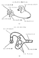
- FIG. 1 is a diagram showing a schematic configuration of a neckband earphone according to a first embodiment of the present invention.
- FIG. 1A is a diagram illustrating a schematic configuration of the entire neckband earphone
- FIG. 1B is a diagram illustrating a schematic configuration of an earphone driver of the neckband earphone.
- the neckband type earphone 10 includes two earphone drivers 20 and a neckband 30.
- the neckband 30 has a U-shape, and earphone drivers 20 are provided at two ends thereof.
- the U-shape of the neckband 30 has a shape in which both ends are slightly curved inward.
- Two earphone drivers 20 are provided on the ears of the wearer, the neckband 30 is disposed on the back side of the neck of the wearer, and the neckband earphone 10 is worn on the wearer.
- the earphone driver 20 includes an earphone section 40, an ear holder section 50, and a holder main body 60.
- the earphone unit 40 is inserted into the wearer's pinna and outputs an audio signal.
- the ear holder unit 50 connects the earphone unit 40 and a holder main body 60 described later, and contacts the upper side of the wearer's pinna to hold the neckband earphone 10.
- the holder body 60 incorporates a driver (not shown) that converts an electrical signal into an audio signal, holds the earphone part 40 via the ear holder part 50, and contacts the head part around the ears of the wearer.
- a cushion part 70 is provided.
- the ear holder 50 of the earphone driver 20 contacts the upper side of the wearer's auricle, and the holder body 60 contacts the head on the rear side of the wearer's auricle. Since both ends of the shaped neckband 30 are curved inward, the neckband earphone 10 is held on the head of the wearer.
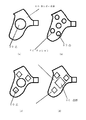
- FIG. 2 is a view for explaining the structure of the cushion part of the neckband earphone according to the first embodiment of the present invention.
- FIG. 2 (a) is a cross-sectional view showing a hollow type cushion part.
- b) is a sectional view showing a cushion portion filled with a filling member.
- a holder main body 60 of the earphone driver 20 shown in FIG. 2B includes a cushion portion 70 formed of a specific number of convex portions 80. As described above, when the earphone driver 20 is mounted on the wearer's auricle, the cushion unit 70 comes into contact with the head on the back side of the wearer's auricle. The cushion part 70 provided to the head directly contacts the wearer's head.
- the convex part 80 of the cushion part 70 is formed of an elastomer member. As shown in FIG. 2A, the convex portion 80 has a hollow portion 81 therein and is filled with air.
- the cushion part 70 is made of a soft material such as an elastomer material so that the cushion part 70 is made hollow and comes into contact with the head so that the convex part 80 of the cushion part 70 is crushed when touched by the wearer. A feeling of adhesion is obtained as well as a feeling.
- it since it is a soft material, a wearer can endure long-time wearing, without giving a pain to a wearer.
- the boulder body 60 itself can be easily manufactured.
- the convex portion 80 of the cushion portion 70 may be filled with a filling member 82 such as gel-like silicon.
- a filling member 82 such as gel-like silicon.
- FIG. 3 is a diagram illustrating another example of the cushion portion in the neckband earphone according to the first embodiment of the present invention.
- the cushion portion 70 is composed of three convex portions 80 and may be composed of one convex portion 80 as shown in FIG.
- 3 (b) you may be comprised by the 2 or more some convex part 80.
- the cushion portion 70 having at least one convex portion 80 can obtain a stable wearing feeling without causing discomfort to the wearing person, and for a long time. Can be installed.
- the convex part 80 of the cushion part 70 may be a combination of one large convex part 80 and a convex part 80 having a smaller size as shown in FIG. 1, and as shown in FIG. You may make it comprise the convex part 80 of the same magnitude
- the cushion portion 70 By configuring the cushion portion 70 with a plurality of convex portions 80 of the same size, the plurality of convex portions 80 come into contact with the head with the same pressure, thereby obtaining a stable wearing feeling in contact with uniform pressure. it can.
- the convex part 80 of the cushion part 70 is comprised by the convex part 80 of the circular convex part 80 and the polygon (a triangle, a tetragon
- the convex portion 80 having a polygonal shape instead of a circular shape the surface having the polygonal side has a restraining force in the movement in the direction of the surface, and the contact surface is displaced from the head of the holder body 60. It becomes prevention of.
- the convex part 80 of the cushion part 70 may be made to form the convex part 80 by various arrangement
- the cushion portion 70 can be configured with various shapes of convex portions 80 in various arrangements as appropriate according to the intended use of the neckband earphone 10.
- the number of the convex portions 80 of the cushion portion 70 is increased, and the shape of the convex portion 80 is made polygonal so that it can be exercised. This prevents the neckband earphone 10 from being displaced from the head due to the vibration of the head.
- the circular convex portion 80 is formed, and the cushion portion 70 constituted by a small number of convex portions 80 is used, so that the head portion can be obtained. It is possible to withstand long-time wearing without giving much contact feeling, and to obtain a stable wearing feeling.
- the neckband earphone 10 of the present embodiment causes the neckband earphone 10 to be firmly attached to the wearer's head by the cushion portion 70 of the holder portion 60 together with the ear holder portion 50 of the earphone driver 20.
- the neckband earphone 10 can be worn for a long time with a stable wearing feeling without the wearer getting uncomfortable feeling. Can be worn.
- the neckband type earphone 10 does not have a protruding tip portion of the neckband 30 used for wearing, even a person who does not know how to use the neckband type earphone 10 wears the neckband type earphone 10. When doing so, there is no danger of poke the ear or head at the tip.
- the neckband type earphone 10 does not have a protruding tip portion of the neckband 30 used when being worn, the tip portion is not broken and broken.
- the neckband earphone 10 of the present embodiment can be worn for a long time without giving the wearer the discomfort of wearing the neckband earphone 10, and the danger to the wearer at the time of wearing is also possible.
- FIG. 4 is a schematic configuration diagram showing a neckband earphone according to a second embodiment of the present invention.
- the neckband earphone 100 includes two head holding units 200, two housings 300, two ear pads 400, two arm units 500, and a neckband unit 600.
- the neckband portion 600 is formed of an elastic body such as a curved rubber member, and includes connection portions 601 that connect the head holding portion 200 to both ends.
- the head holding unit 200 is connected to the connection unit 601.
- the two head holding portions 200, the housing 300, the ear pad 400, and the arm portion 500 are arranged so as to be symmetrical with respect to the neckband portion 600.
- the head holding unit 200 includes an operation unit 800 on a surface that is on the outer side with respect to the neckband unit 600.
- the arm portion 500 is made of an elastic body such as a rubber member, and forms a cylindrical shape with a hollow inside. One end of the arm unit 500 is fixed to the upper surface portion of the head holding unit 200 and the housing 300 is fixed to the other end.
- the housing 300 holds the ear pad 400 on the inner surface of the neckband portion 600.
- FIG. 5 is a side view showing the head holding part 200, the arm part 500, and the housing 300 of the neckband earphone 100 according to the second embodiment of the present invention.
- the upward direction is above the neckband earphone 100
- the right direction is the front of the neckband earphone 100.
- the arm part 500 is formed in a state of being curved in a substantially semicircular shape.
- the head holding portion 200 has a curved surface portion 208 formed on the front surface.
- the curved inner surface of the arm unit 500 is disposed in a state of being smoothly continuous with the curved surface of the curved surface unit 208.
- the arm portion 500 is configured to be deformable in the arrow direction by pressing the housing 300 forward or backward due to the elasticity of the elastic body.
- FIG. 6 is a cross-sectional view taken along the line AA showing the housing 300 and the ear pad 400 of the neckband earphone 100 shown in FIG.
- the upper direction is above the housing 300 and the ear pad 400
- the right direction is the inside of the housing 300 and the ear pad 400.
- the housing 300 includes a driver unit 700 inside.
- the housing 300 forms a cylindrical shape having a hollow portion 302 therein, and has a hole 301 in the upper part.
- the hole 301 penetrates the hollow portion inside the arm unit 500.
- the housing 300 includes a convex portion 304 that is formed in a cylindrical shape in the inner portion and includes a hole 303 that penetrates inward from the cavity portion 302.
- the convex part 304 is provided with a groove part 305 in the central part of the outer periphery.
- the driver unit 700 includes a vibration plate (not shown), and is fixed to the inner wall of the housing 2 with an adhesive or the like so that the vibration plate is exposed from the hole 303 to the inside.
- the lead wire 140 is electrically connected to the driver unit 700.
- the lead wire 140 is electrically connected to an audio signal output unit of the head holding unit 200 described later via a hole 301 and through a cavity inside the arm unit 500.
- the ear pad 400 is formed in a cylindrical shape by an elastic body such as a rubber member, and includes a hole 401 penetrating in the front-rear direction.
- the ear pad 400 includes a flange portion 402 protruding in the inner circumferential direction.
- the ear pad 400 is held inside the housing 300 by fitting the collar portion 402 into the groove portion 305 of the convex portion 303.
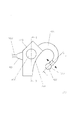
- FIG. 7 is a BB cross-sectional view showing the head holding part 200 of the neckband earphone 100 shown in FIG. In FIG. 7, the upward direction is above the head holding unit 200, and the right direction is the inside of the head holding unit 200.
- the head holding unit 200 includes a chassis unit 201, a cover unit 203, a contact unit 206, a substrate 900, a switch 1000, an audio signal receiving unit 110, a control unit 120, an audio signal output unit 130, and a battery 150. Is provided.
- the chassis unit 201 forms a box shape that opens to the outside, and includes a recess 202.
- the cover part 203 has a plate shape and is fixed so as to cover the recess 202 from the outside of the chassis part 201.
- the substrate 900 is held inside the recess 202 by a boss 205 fixed to the inner wall of the chassis unit 201, and fixes the switch 1000, the audio signal receiving unit 110, the control unit 120, and the audio signal output unit 130.
- the battery 150 supplies power to the switch 1000, the audio signal receiving unit 110, the control unit 120, and the audio signal output unit 130 through the substrate 900.
- the battery 150 is configured to be provided inside the chassis unit 201 and the cover unit 203, but may be configured to be detachable from the lower surface of the chassis unit 201, and the cover unit 203 includes an opening / closing cover.
- the battery 150 provided inside the chassis unit 201 may be detachable.
- the audio signal receiving unit 110 receives an audio signal transmitted by radio waves from a playback device (not shown).
- the operation unit 800 includes a shaft on the inner side, and the shaft is connected to a switch 1000 fixed to the substrate 900 through a hole 204 provided in the cover unit 203.
- the switch 1000 outputs an audio signal playback start or playback stop instruction signal when the operation unit 800 is pressed inward.
- the control unit 120 controls the audio signal receiving unit 110 and the audio signal output unit 130. Based on the instruction signal from the switch 1000, the control unit 120 controls the audio signal output unit 130 to start or stop outputting the audio signal received by the audio signal receiving unit 110.
- the audio signal output unit 130 is electrically connected to the driver unit 700 provided in the housing 300 through the lead wire 140 as described above, and the audio signal received by the audio signal receiving unit 110 based on the control of the control unit 120. A signal is output to the driver unit 700.
- the contact portion 206 is made of a plate-like elastic body such as a rubber member, and is fixed to the inner side surface of the chassis portion 201. As shown in FIGS. 4 and 7, the contact portion 206 includes a plurality of dimple portions 207 each having a concave shape on the inner surface.
- the neckband portion 600 is attached to the user's head, the curved surface portion 208 of the head holding portion 200 is brought into contact with the back of the earlobe and the arm portion.
- the ear pad 400 is fitted into the ear with 500 being put on the top of the ear.
- the neckband type earphone 100 has a head that is sandwiched between the user's left and right ears by the contact part 206 of the head holding part 200 due to the elasticity of the neckband part 600 and abutted against the rear part of the earlobe by the elasticity of the arm part 500.
- the ear is sandwiched between the curved surface portion 208 and the ear pad 400 of the holding portion 200. Accordingly, the neckband earphone 100 is attached to the user's head and ears.
- the playback device (not shown) is operated so that the audio signal is transmitted by radio waves from the transmission unit of the playback device.
- the neckband earphone 100 When an audio signal is transmitted by radio waves from the transmission unit of the playback device, the neckband earphone 100 inputs an audio signal transmitted by radio waves from the transmission unit of the playback device by the audio signal reception unit 110.
- the control unit 120 controls the audio signal output unit 130 to output the audio signal input by the audio signal receiving unit 110 when the operation unit 800 is pressed by the user and an instruction signal instructing reproduction is output from the switch 1000.
- the audio signal output unit 130 outputs the audio signal input from the audio signal receiving unit 110 to the driver unit 700 via the lead wire 140 based on the control of the control unit 120.
- the driver unit 700 converts the audio signal input from the audio signal output unit 130 into a vibration by a magnetic circuit, and transmits the vibration to a diaphragm via a voice coil (not shown) to emit the audio signal.
- the audio signal reproduced by the reproduction apparatus is emitted by the driver unit 700 via the audio signal receiving unit 110, the audio signal output unit 130, and the lead wire 140, and the emitted audio signal is output from the hole of the housing 300.
- This is transmitted to the inside of the ear pad 400 via 303.
- the audio signal is transmitted to the ear of the user wearing the ear pad 400, and the user can listen to the audio signal output from the neckband earphone 100.
- the neckband earphone 100 has the back of the user's left and right ears sandwiched by the contact part 206 of the head holding part 200 due to the elasticity of the neckband part 600, and the rear part of the earlobe due to the elasticity of the arm part 500.
- the neckband earphone 100 can be accurately attached to the user's head and ear.
- the contact portion 206 that comes into contact with the rear of the left and right ear portions of the user is provided with a plurality of dimple portions 207 each having a concave shape on the surface thereof, so that the surface of the head portion behind the user's ear portion can be dimpled. It is in a state of being gripped by the recess 207. Therefore, even if the head holding unit 200 includes the audio signal receiving unit 110, the audio signal output unit 130, the battery 150, and the like for receiving the audio signal transmitted from the playback device, the dimple of the contact unit 206 is provided.
- the neckband earphone 100 When the unit 207 holds the surface of the user's head in a gripped state, for example, even if the user wears the neckband earphone 100 and performs sports such as walking or jogging by commuting, the neckband earphone It is possible to prevent 100 from falling off or slipping from the ear.
- the neckband earphone 100 also includes various circuits and a battery 150 for receiving an audio signal transmitted from the playback device and outputting the audio signal to the driver unit 700 as an audio signal.
- the neckband earphone 100 By providing the inside of the head holding unit 200 that comes into contact with the surface of the unit, for example, the user's head vibrates up and down by performing sports such as walking and jogging by commuting while wearing the neckband earphone 100 Even so, the arm portion 500 and the dimple portion 207 of the contact portion 206 cause the weight of the head holding portion 200 to be distributed and evenly distributed to the peripheral portion of the user's ear. It can be continuously attached accurately.
- the neckband earphone 100 for example, a headband by vibration in the vertical direction of the neckband earphone, such as a neckband earphone provided with various circuits and a battery in the rear portion of the neckband portion. It is possible to prevent the wearability of the neckband type earphone from being impaired due to the tilting forward or backward.
- the neckband earphone 100 of the present embodiment includes an operation unit 800 on the outer side surface of the head holding unit 200, and the user can play or stop the audio signal when the user presses the operation unit 800.
- the user presses the dimple part 207 of the contact part 206 against the user's head every time the operation part 800 is pressed in order to start or stop the reproduction of the audio signal.
- the user can press the operation unit 800 and the head surface of the rear part of the user's ear can be newly grasped in the dimple of the dimple unit 207.
- the band-type earphone 100 can be securely attached to the user's head.
- the neckband earphone 100 of the present embodiment has a configuration in which the contact portion 206 including the dimple portion 207 is formed of an elastic body.
- the contact portion 206 may be a metal member or a plastic member other than the elastic body. Thereby, since various coloring and decoration can be given to the contact part 206, the beauty
- the neckband earphone 100 of the present embodiment is configured to receive an audio signal transmitted by radio waves from the playback device by the audio signal receiving unit 110, but the audio signal is transmitted from the playback device by infrared rays or other data transmission means.
- the audio signal transmitted by these transmitting means may be received by the audio signal receiving unit.
- the audio signal may be input through a cable or the like without receiving the audio signal from the reproduction apparatus by wireless means such as radio waves.
- the neckband earphone 100 of the present embodiment is configured to output an audio signal reproduction start or reproduction stop instruction signal when the operation unit 800 of the head holding unit 200 is pressed, but other than the reproduction start or stop In addition, for example, it may be configured such that instructions such as volume adjustment of an audio signal output from the driver unit 700, designation of a reproduction track, designation of a reproduction tempo, and the like can be performed.
- the neckband earphone 100 of the present embodiment is configured such that a playback device that plays back an audio signal is another device other than the neckband earphone 100 and receives an audio signal transmitted from the playback device.
- the head holding unit 200 of the band-type earphone 100 may include a storage unit that stores an audio signal and a playback unit, and the playback unit may play back the audio signal stored in the storage unit.
- the audio signal can be heard only by the neckband type earphone without providing another playback device other than the neckband type earphone 100. Therefore, when the user performs sports such as walking or jogging by commuting. You can concentrate on sports without worrying about connecting cables.
- the present invention can be usefully used for a neckband type earphone.
- neckband earphones 10 neckband earphones, 20 earphone drivers, 30 neckbands, 40 earphones, 50 ear holders, 60 holder body, 70 cushion part, 80 convex part, 81 hollow part, 82 filling member, 100 neckband earphones, 200 head holder, 201 chassis, 202 recess, 203 cover, 204 holes, 205 boss, 206 contact portion, 207 dimple portion, 208 curved surface portion, 300 housing, 301 hole, 302 cavity, 303 hole, 304 convex portion, 305 groove portion, 400 ear pads, 401 holes, 402 buttocks, 500 arm part, 600 neckband part, 601 connection part, 700 Driver unit, 800 operation unit, 900 board, 1000 switch, 110 audio signal receiving unit, 120 control unit, 130 audio signal output unit, 140 lead wire, 150 battery
Landscapes
- Physics & Mathematics (AREA)
- Engineering & Computer Science (AREA)
- Acoustics & Sound (AREA)
- Signal Processing (AREA)
- Health & Medical Sciences (AREA)
- Otolaryngology (AREA)
- Headphones And Earphones (AREA)
Abstract
La présente invention vise à proposer un écouteur de type serre-nuque qui peut être porté pendant un temps long sans soumettre le porteur à un inconfort de port d'un écouteur de type serre-nuque, et dans lequel l'extension de risque au porteur lorsqu'il est porté est diminuée et des positions qui rompent sont réduites. A cet effet, la présente invention porte sur un écouteur de type serre-nuque comportant : des parties d'écouteur qui sont insérées dans les pavillons de l'oreille du porteur et qui délivrent en sortie un signal audio ; des parties de dispositif de maintien à l'oreille qui relient les parties d'écouteur et qui viennent en butée contre le côté supérieur des pavillons de l'oreille du porteur ; des corps de dispositif de maintien comportant les parties du dispositif de maintien à l'oreille ; des pilotes d'écouteur comportant les corps de dispositif de maintien ; et un serre-nuque reliant les deux pilotes d'écouteur ; les corps de dispositif de maintien comportant une partie de coussin à une partie qui vient en contact avec la tête du porteur au voisinage des pavillons de l'oreille.
Priority Applications (2)
| Application Number | Priority Date | Filing Date | Title |
|---|---|---|---|
| US14/367,560 US9398363B2 (en) | 2011-12-22 | 2012-12-12 | Neckband-type earphone |
| EP12859150.0A EP2802155A4 (fr) | 2011-12-22 | 2012-12-12 | Ecouteur de type serre-nuque |
Applications Claiming Priority (4)
| Application Number | Priority Date | Filing Date | Title |
|---|---|---|---|
| JP2011-281899 | 2011-12-22 | ||
| JP2011281899 | 2011-12-22 | ||
| JP2011285729 | 2011-12-27 | ||
| JP2011-285729 | 2011-12-27 |
Publications (1)
| Publication Number | Publication Date |
|---|---|
| WO2013094484A1 true WO2013094484A1 (fr) | 2013-06-27 |
Family
ID=48668377
Family Applications (1)
| Application Number | Title | Priority Date | Filing Date |
|---|---|---|---|
| PCT/JP2012/082161 WO2013094484A1 (fr) | 2011-12-22 | 2012-12-12 | Ecouteur de type serre-nuque |
Country Status (4)
| Country | Link |
|---|---|
| US (1) | US9398363B2 (fr) |
| EP (1) | EP2802155A4 (fr) |
| JP (1) | JP6026235B2 (fr) |
| WO (1) | WO2013094484A1 (fr) |
Families Citing this family (7)
| Publication number | Priority date | Publication date | Assignee | Title |
|---|---|---|---|---|
| CN108496373B (zh) * | 2016-02-01 | 2020-08-21 | 索尼公司 | 声音输出装置 |
| KR101805535B1 (ko) | 2016-04-22 | 2017-12-07 | 엘지전자 주식회사 | 휴대용 전자기기 |
| KR102507744B1 (ko) | 2016-08-09 | 2023-03-09 | 삼성전자주식회사 | 웨어러블 전자 장치 및 그 동작 방법 |
| KR101835337B1 (ko) * | 2016-08-26 | 2018-03-07 | 엘지전자 주식회사 | 휴대용 음향기기 |
| KR102029076B1 (ko) * | 2018-02-13 | 2019-10-10 | 주식회사 이엠텍 | 종속 진동부를 구비한 마이크로스피커 모듈을 채용한 넥밴드 스피커 |
| US10674244B2 (en) * | 2018-02-21 | 2020-06-02 | Bose Corporation | Audio device |
| US10924838B1 (en) * | 2019-09-11 | 2021-02-16 | Bose Corporation | Audio device |
Citations (7)
| Publication number | Priority date | Publication date | Assignee | Title |
|---|---|---|---|---|
| JPH0681193U (ja) * | 1993-04-19 | 1994-11-15 | 清 杉山 | 首掛けレシ−バ− |
| JP2002238092A (ja) | 2001-02-08 | 2002-08-23 | Sanyo Electric Co Ltd | ヘッドホン装置 |
| JP2007013873A (ja) | 2005-07-04 | 2007-01-18 | Sony Corp | ヘッドホン装置 |
| JP2008161429A (ja) * | 2006-12-28 | 2008-07-17 | Yamaha Corp | 脈拍検出機能を備えたヘッドフォン |
| JP2008227754A (ja) | 2007-03-09 | 2008-09-25 | Sony Corp | ヘッドホン装置 |
| WO2010116510A1 (fr) * | 2009-04-09 | 2010-10-14 | 日本エムエムアイテクノロジー株式会社 | Dispositif à microphone et dispositif à casque d'écoute |
| JP2010268030A (ja) * | 2009-05-12 | 2010-11-25 | Yone Kk | ヘッドセット、及びこれを用いた情報伝送システム |
Family Cites Families (9)
| Publication number | Priority date | Publication date | Assignee | Title |
|---|---|---|---|---|
| GB1091490A (en) * | 1966-06-22 | 1967-11-15 | Standard Telephones Cables Ltd | Improvements in or relating to headsets |
| JP3057731B2 (ja) * | 1990-08-21 | 2000-07-04 | ソニー株式会社 | 電気音響変換器及び音響再生システム |
| EP0779763A1 (fr) * | 1995-12-13 | 1997-06-18 | Augusto Salzani | Casque d'écoute amélioré avec des écouteurs séparés et moyens pour son couplage aux oreilles |
| US6233345B1 (en) | 1998-05-05 | 2001-05-15 | Peter Urwyler | Personal earphone assembly for mounting upon eyeglasses |
| US7209177B2 (en) * | 2002-09-03 | 2007-04-24 | Audisoft | Headset for camera |
| US20080260197A1 (en) * | 2004-12-30 | 2008-10-23 | Polito Fred I | Adjustable earhook |
| JP5082764B2 (ja) * | 2007-10-25 | 2012-11-28 | ソニー株式会社 | イヤパッド及びヘッドホン装置 |
| CN101861180B (zh) * | 2007-11-15 | 2014-07-16 | 雷斯梅德有限公司 | 一种缓冲结构 |
| JP2010157896A (ja) * | 2008-12-26 | 2010-07-15 | Sony Corp | 再生装置及びヘッドホン装置 |
-
2012
- 2012-11-15 JP JP2012251192A patent/JP6026235B2/ja active Active
- 2012-12-12 WO PCT/JP2012/082161 patent/WO2013094484A1/fr active Application Filing
- 2012-12-12 EP EP12859150.0A patent/EP2802155A4/fr not_active Ceased
- 2012-12-12 US US14/367,560 patent/US9398363B2/en active Active
Patent Citations (7)
| Publication number | Priority date | Publication date | Assignee | Title |
|---|---|---|---|---|
| JPH0681193U (ja) * | 1993-04-19 | 1994-11-15 | 清 杉山 | 首掛けレシ−バ− |
| JP2002238092A (ja) | 2001-02-08 | 2002-08-23 | Sanyo Electric Co Ltd | ヘッドホン装置 |
| JP2007013873A (ja) | 2005-07-04 | 2007-01-18 | Sony Corp | ヘッドホン装置 |
| JP2008161429A (ja) * | 2006-12-28 | 2008-07-17 | Yamaha Corp | 脈拍検出機能を備えたヘッドフォン |
| JP2008227754A (ja) | 2007-03-09 | 2008-09-25 | Sony Corp | ヘッドホン装置 |
| WO2010116510A1 (fr) * | 2009-04-09 | 2010-10-14 | 日本エムエムアイテクノロジー株式会社 | Dispositif à microphone et dispositif à casque d'écoute |
| JP2010268030A (ja) * | 2009-05-12 | 2010-11-25 | Yone Kk | ヘッドセット、及びこれを用いた情報伝送システム |
Non-Patent Citations (1)
| Title |
|---|
| See also references of EP2802155A4 |
Also Published As
| Publication number | Publication date |
|---|---|
| JP6026235B2 (ja) | 2016-11-16 |
| EP2802155A1 (fr) | 2014-11-12 |
| EP2802155A4 (fr) | 2015-08-05 |
| US9398363B2 (en) | 2016-07-19 |
| US20150172802A1 (en) | 2015-06-18 |
| JP2013153415A (ja) | 2013-08-08 |
Similar Documents
| Publication | Publication Date | Title |
|---|---|---|
| JP6026235B2 (ja) | ネックバンド型イヤーホン | |
| JP5473640B2 (ja) | スピーカー装置 | |
| WO2013099429A1 (fr) | Dispositif formant casque d'écoute | |
| US20160100237A1 (en) | Integrated Personal Electronic Device | |
| JP2010157974A (ja) | 骨伝導マイクロホン内蔵ヘッドセット | |
| JP2006279235A (ja) | ヘッドホン装置及びヘッドホンシステム | |
| JP2013153415A5 (ja) | イヤーホン及びネックバンド型イヤーホン | |
| KR101694706B1 (ko) | 이어셋 | |
| US9973841B2 (en) | Earbud set, and hearing aid and earphone using same | |
| JP2020113890A (ja) | 聴音装置 | |
| KR101366001B1 (ko) | 진동기능이 있는 헤드폰 | |
| US20230276156A1 (en) | Sound output device | |
| JP7067477B2 (ja) | 音響出力装置 | |
| JP2000201390A (ja) | ヘッドホン | |
| US20190037296A1 (en) | Sound output device | |
| CN111988696A (zh) | 耳机 | |
| US20240073578A1 (en) | Earphone housing and earphone | |
| CN220653511U (zh) | 一种半入耳式骨传导耳机 | |
| US20240147115A1 (en) | Open-ear bluetooth earphone | |
| EP3094107A1 (fr) | Dispositif d'écoute audio | |
| KR102177999B1 (ko) | 헬멧용 골전도 헤드폰 | |
| KR20080073074A (ko) | 헤드셋 | |
| KR20170090169A (ko) | 착탈식 전자 웨어 장치 | |
| CN117676407A (zh) | 一种耳机 | |
| JP2004104400A (ja) | ヘッドセット装置 |
Legal Events
| Date | Code | Title | Description |
|---|---|---|---|
| 121 | Ep: the epo has been informed by wipo that ep was designated in this application |
Ref document number: 12859150 Country of ref document: EP Kind code of ref document: A1 |
|
| WWE | Wipo information: entry into national phase |
Ref document number: 14367560 Country of ref document: US |
|
| NENP | Non-entry into the national phase |
Ref country code: DE |
|
| WWE | Wipo information: entry into national phase |
Ref document number: 2012859150 Country of ref document: EP |